


Languages
Pages
Legal


Webcast - 23 July 2015
Test & Measurement Trends for Aerospace and Defense
John Hansen
Keysight Technologies

Page Agenda
The Aerospace & Defense / Test & Measurement Ecosystem
A coming renaissance for the military and defense industry
Aerospace and defense spending
New T & M Demands from the Industry
Testing Array Antennas
The Move into mm Wave
Renaissance in Electronic Warfare (EW) and Signals Intelligence (SIGINT)
The Effect of NewSpace on Satellite Technologies
Mixed Signal Test for AD Applications
Radar Target Simulation Requires Cost Effective Tools
© Keysight
Technologies 2015 2
Page
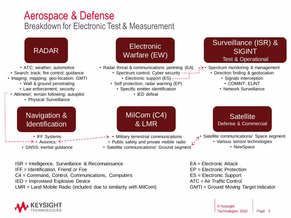
Aerospace & Defense Breakdown for Electronic Test & Measurement
ISR = Intelligence, Surveillance & Reconnaissance
IFF = Identification, Friend or Foe
C4 = Command, Control, Communications, Computers
IED = Improvised Explosive Device
LMR = Land Mobile Radio (included due to similarity with MilCom)
Electronic
Warfare (EW)
Surveillance (ISR) &
SIGINT Test & Operational
RADAR
MilCom (C4)
& LMR
• Military terrestrial communications
• Public safety and private mobile radio
• Satellite communications/ Ground segment
Navigation &
Identification Satellite
Defense & Commercial
• IFF Systems
• Avionics;
• GNSS; inertial guidance
• ATC; weather; automotive
• Search; track; fire control; guidance
• Imaging; mapping; geo-location; GMTI
• Wall & ground penetrating
• Law enforcement; security
• Altimeter; terrain following; autopilot
• Physical Surveillance
EA = Electronic Attack
EP = Electronic Protection
ES = Electronic Support
ATC = Air Traffic Control
GMTI = Ground Moving Target Indicator
• Radar threat & communications jamming (EA)
• Spectrum control; Cyber security
• Electronic support (ES)
• Self protection; radar warning (EP)
• Specific emitter identification
• IED defeat
• Satellite communications/ Space segment
• Various sensor technologies
• NewSpace
• Spectrum monitoring & management
• Direction finding & geolocation
• Signals interception
• COMINT; ELINT
• Network Surveillance
3
© Keysight
Technologies 2015

Page
The Aerospace & Defense Ecosystem – Value Chain Segmentation Government Agencies
Military
Commercial SatCom & Airlines
(Service Providers)
Prime Contractors Sub-Contractors
Small Suppliers & MRO Services
MRO: Maintenance, Repair & Operations
Component
Manufacturers
Electronic Design Automation (EDA)
General Purpose Products
Signal Sources Signal Analyzers Network Analyzers
Optical Test High Speed Digital High Performance Oscilloscopes
4
© Keysight
Technologies 2015

Page
Forces at Work in the Industry
There is a concerted effort world-wide to build smaller, more
technologically capable military forces. Even though overall budgets may be flat or shrinking in most countries, the
money earmarked for technology advancement, will grow significantly
Increasing technology parity with potential adversaries and the need for an
increase in acquisition efficiency is driving this effort
Information and information flow (Cyber) is a new domain of warfare
and has gained a great deal of attention world wide
Political drivers in the form of export controls and economic sanctions
are in a state of continuous change
5
© Keysight
Technologies 2015

Page
New Demands from the A/D Industry
Need to move acquired or stored RF signal data from one instrument
to another at a minimum rate of at least 10 GB/s (equivalent to 2 GHz
modulation bandwidth).
Need high speed (to real time) data reduction/analysis within the
instrument (FPGA/DSP/GPU) – can no longer rely on instrument
controller
Must have multiple, coherent, RF channels for signal generation and
analysis
Need wideband capabilities with comparable bandwidth for both signal
generation and signal analysis
More ease-of-use, lower time to first measurement and faster
stimulus/response measurement time
Test Tools need to Evolve Along with (or faster than) Advanced System Capabilities
6
© Keysight
Technologies 2015

Page
Testing Array Antennas and Transmit / Receive Modules (TRM)
7 7
AESA Airborne, 100-3000+ active elements
© Keysight
Technologies 2015

Page
Active Electronically Scanned Phased Array (AESA) Antennas
Key Benefits
• Fixed position antenna
• Flexible beam shape
• Fast steering with precision
• Ability to form multiple agile beams
• Communicate with multiple spatially distributed ground stations or terminals
• Operate in multiple modes engaging multiple threats or targets
• Independent transmit/receive modules per element
• Reduced power loss from integration of RF source on each T/R module
• Graceful degradation – single source failure will not cripple system
Multiple Spot Beams are created from a single array antenna
8
© Keysight
Technologies 2015
Page
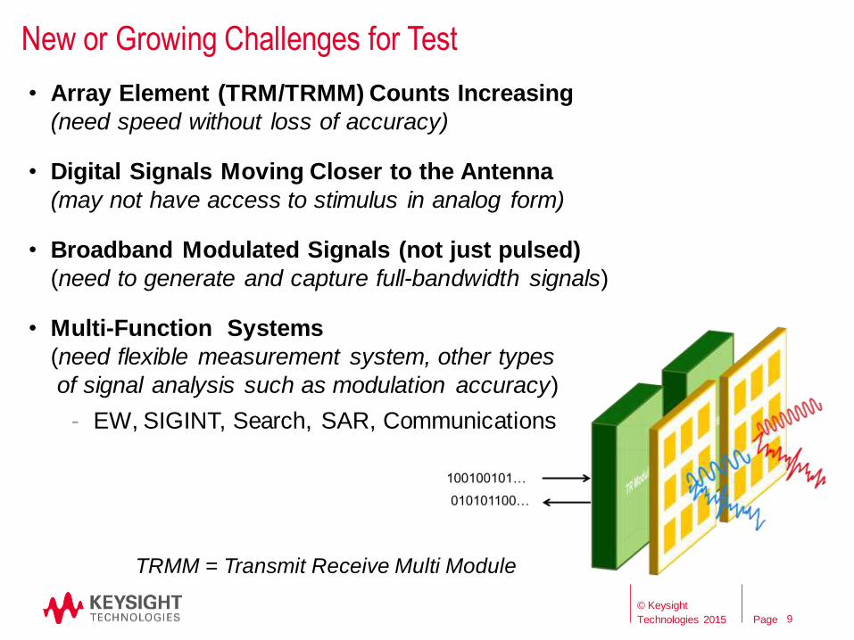
New or Growing Challenges for Test
• Array Element (TRM/TRMM) Counts Increasing
(need speed without loss of accuracy)
• Digital Signals Moving Closer to the Antenna
(may not have access to stimulus in analog form)
• Broadband Modulated Signals (not just pulsed)
(need to generate and capture full-bandwidth signals)
• Multi-Function Systems
(need flexible measurement system, other types
of signal analysis such as modulation accuracy)
- EW, SIGINT, Search, SAR, Communications
9
TRMM = Transmit Receive Multi Module
© Keysight
Technologies 2015 9

Page
Using Wide Bandwidth Signals to Increase Test Throughput
Traditional Approach to TR Module Cal
(speed limited by synchronization and state programming) 1) Set gain/phase
2) Measure narrow band S21 (noise reduction via narrow RBW and integration time)
3) Repeat for each gain/phase combo, and each frequency
10
Thinking about the problem in a different way (speed limited by data transfer) 1) Apply a test signal such as a tone.
2) Rapidly change the gain/phase shifters to modulate the test signal through all possible
states in a pseudo-random fashion. (noise reduction via state duration)
3) Capture the wideband “QAM” modulated signal, synchronize to the modulation patterns
and analyze.
4) Repeat for each frequency Dynamic approach more closely matches operation
© Keysight
Technologies 2015

Page
Multi-channel Solution for Array Antenna Alignment and Calibration
11
A multichannel coherent test capability is optimum for array antenna testing. This example system uses a multichannel digitizer in place of a network analyzer. This configuration provides more channels for simultaneous testing and the ability to provide wideband analysis greatly improving measurement speed.
11
© Keysight
Technologies 2015
Page
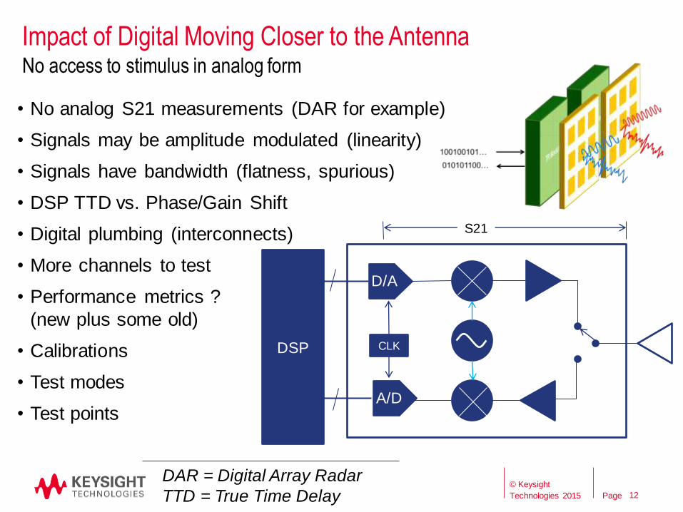
Impact of Digital Moving Closer to the Antenna
12
• No analog S21 measurements (DAR for example)
• Signals may be amplitude modulated (linearity)
• Signals have bandwidth (flatness, spurious)
• DSP TTD vs. Phase/Gain Shift
• Digital plumbing (interconnects)
• More channels to test
• Performance metrics ?
(new plus some old)
• Calibrations
• Test modes
• Test points
DSP
D/A
A/D
S21
CLK
DAR = Digital Array Radar
TTD = True Time Delay
No access to stimulus in analog form
12
© Keysight
Technologies 2015
Page
The Move into Millimeter Wave
13 13
© Keysight
Technologies 2015
Page
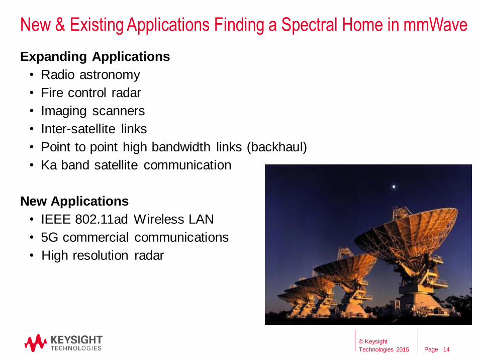
New & Existing Applications Finding a Spectral Home in mmWave
Expanding Applications
• Radio astronomy
• Fire control radar
• Imaging scanners
• Inter-satellite links
• Point to point high bandwidth links (backhaul)
• Ka band satellite communication
New Applications
• IEEE 802.11ad Wireless LAN
• 5G commercial communications
• High resolution radar
14
© Keysight
Technologies 2015
Page
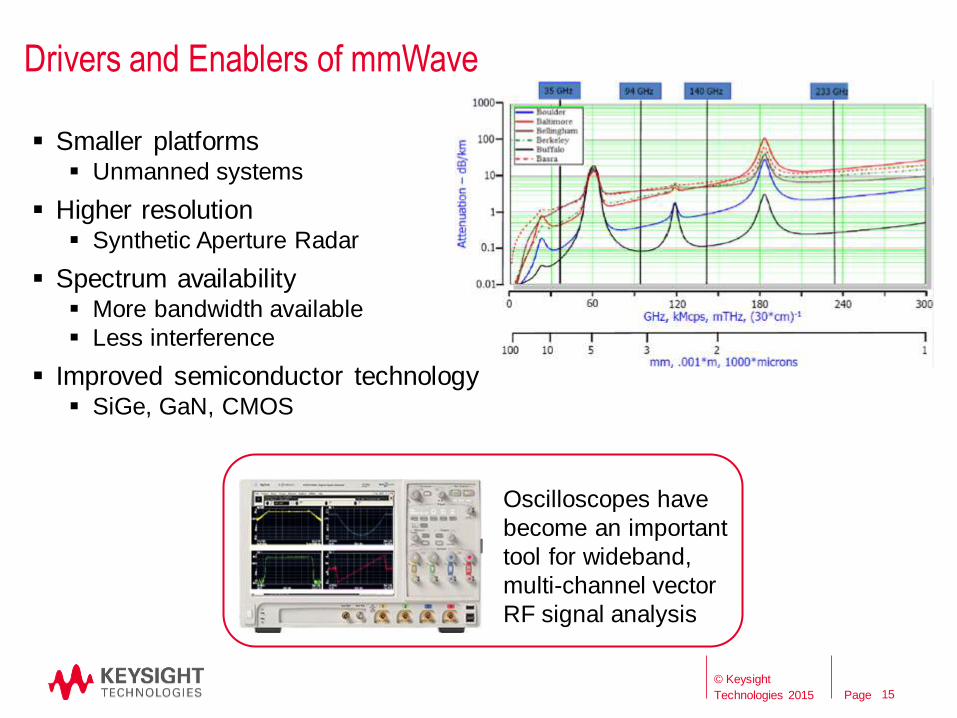
Drivers and Enablers of mmWave
15 15
Smaller platforms Unmanned systems
Higher resolution Synthetic Aperture Radar
Spectrum availability More bandwidth available
Less interference
Improved semiconductor technology SiGe, GaN, CMOS
Oscilloscopes have
become an important
tool for wideband,
multi-channel vector
RF signal analysis
© Keysight
Technologies 2015
Page
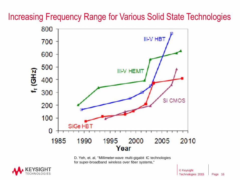
Increasing Frequency Range for Various Solid State Technologies
16
D. Yeh, et. al, “Millimeter-wave multi-gigabit IC technologies
for super-broadband wireless over fiber systems,"
© Keysight
Technologies 2015

Page
Measurement Challenges at Millimeter Frequencies
• Inability to penetrate walls, foliage, rain, etc.
• Higher losses as frequencies increase
• Smaller and more fragile cables (or waveguide) and adapters
• Costs for equipment and accessories are high
• Lack of power standards above 110 GHz
1 mm to 1.85 mm adapter
Retail price: $2400
17
© Keysight
Technologies 2015

Page
Renaissance in Electronic Warfare (EW) and Signals Intelligence (SIGINT)
18
© Keysight
Technologies 2015
Page
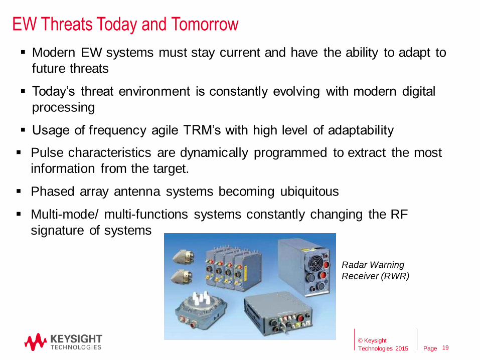
EW Threats Today and Tomorrow
19
Modern EW systems must stay current and have the ability to adapt to
future threats
Today’s threat environment is constantly evolving with modern digital
processing
Usage of frequency agile TRM’s with high level of adaptability
Pulse characteristics are dynamically programmed to extract the most
information from the target.
Phased array antenna systems becoming ubiquitous
Multi-mode/ multi-functions systems constantly changing the RF
signature of systems
19
Radar Warning
Receiver (RWR)
© Keysight
Technologies 2015

Page
The Differences Between EW and Radar Require Somewhat Different Test Methods
20
Bandwidth EW systems require wider instantaneous bandwidths.
Power Radar requires very high power at low duty cycle
EW applications require high power at close to 100% duty
cycle for certain modes of operation.
Frequency Range EW systems have a wider range of frequency of operation to address many different
threats
Antenna Characteristics Both benefit from AESA technologies (beam shaping, multiple beams & beam steering)
Fundamental beam shapes can vary. (ie: Jammer beam may be broad, radar more
narrow).
Signal Processing Radar focused on measuring the range and velocity of a target and calculating the
acceleration in order to sustain tracking.
EW involves identifying threat signals and characterizing them to then produce an
appropriate response (e.g. wideband, narrowband, deceptive).
20
Pantsir S1 (SA-22 Greyhound) SAM system
© Keysight
Technologies 2015

Page
System Operational Platform Evolution Moving from Distributed to more Integrated Architectures
Platform with Distributed Systems Platform with Integrated Systems
Radar
EW – Electronic
Attack
Radar
EW – Electronic
Attack SIGINT Signals
Intelligence Avionics &
Comms
Avionics &
Comms SIGINT Signals
Intelligence
.
.
.
Central
Controller
Test solutions need to become software/firmware
definable with common hardware elements
21
© Keysight
Technologies 2015

Page
Signal Analysis
The Basic Building Blocks of an Off-the-Shelf Solution
22
EW System
Under Test
Signal Stimulus Signal Analysis
Multichannel (>=8?)
Coherent channels
Wideband (5 GHz)
Scenario Creation Downconversion
Multichannel (>=8?)
Coherent channels
Wideband (5 GHz)
Tunable LO
Filtered
Amplified/Attenuated
Automatic Level Control
Upconversion
Real-time analysis
Multichannel calibration and
alignment
PDW list generation
Temporal and statistical
pulse/pulse train analysis
Multiple coherent channels
IQ, IF, or interpret PDWs
FPGA access for custom and
reactive waveforms
Multiple dynamic emitters
Long scenarios
IQ, IF, or PDW list
Scenario Generation
Reference waveforms
Synchronization
Control connections
Signal Capture
Multiple coherent channels
Adjustable pre-selection and
filtering
Deep memory capture
22
© Keysight
Technologies 2015

Page
Pulse Descriptor Words (PDW) to Describe and Simulate Threats
23
Contains temporal pulse information for each pulse received
• Example: Frequency, amplitude, PRI, pulse width, delta TOA, TOA, target designator or ID, range, velocity, AOA, etc.
The structures of PDWs vary widely depending on required detail and application
• There are commonly utilized formats
Use deinterleaving of pulses in a multi-emitter environment to isolate the train from each specific emitter
• Separate PDWs into groups of pulses with parametric and inter-pulse consistency
• Pulse overlap handling determined on a user defined priority basis (e.g. strongest signal)
23
Mitigates the Problem of Huge Signal Data Files
© Keysight
Technologies 2015

Page
Trends in Satellite Technologies The Effect of NewSpace on Satellite Technologies
Sputnik 1 Project SCORE MILSTAR Boeing 702HP
24
© Keysight
Technologies 2015 24

Page
More Regenerative Payloads Vector Modulation and Demodulation as Part of Signal Path
ADC
DAC
Demodulator
Modulator
FEC
Encode
DSP
Conventional
Hardware Digital
Signal
Processing
Digitally regenerative satellites greatly expand test plans
compared to classical bent pipe architectures
(animations) 25
© Keysight
Technologies 2015

Page
Commercial Satellite Market Trends - NewSpace
Definition from NewSpace Global
NewSpace is an emerging global industry of private companies and
entrepreneurs who primarily target commercial customers, are
backed by risk capital seeking a return, and profit from innovative
products or services developed in or for space.
NewSpace is not a new industry so much as it is a major disruptive force
in the space industry as a whole
Characteristics of NewSpace
Primary objective is to make a profit from risk-based investment
Commercial business and funding models
Willingness to take risk
Background / Context
https://www.newspaceglobal.com/
© Keysight
Technologies 2015 26 26
Page
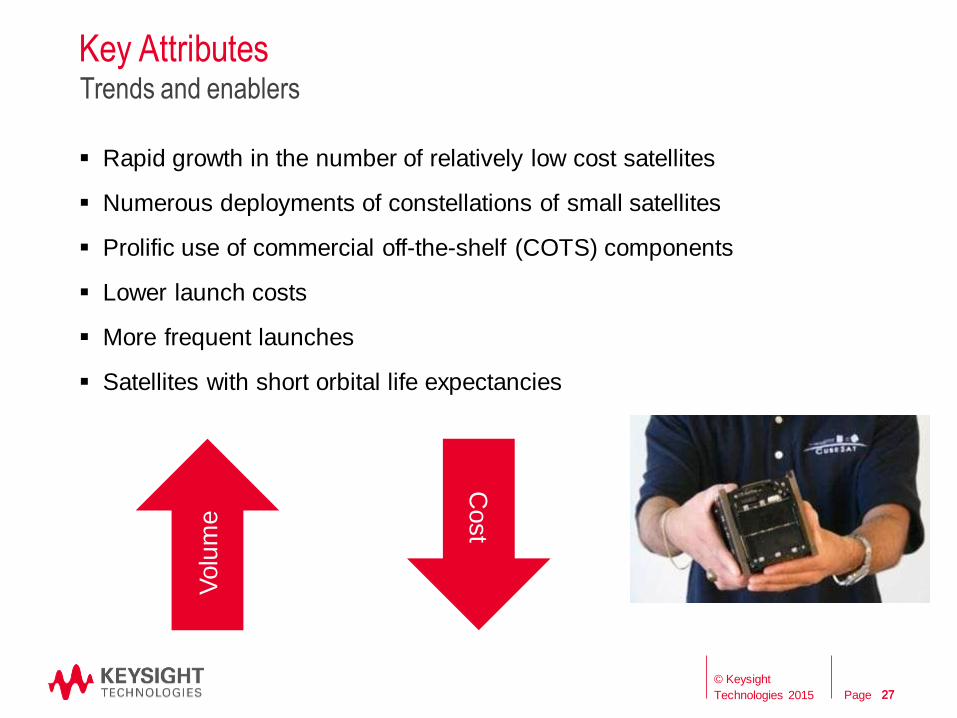
Key Attributes
Rapid growth in the number of relatively low cost satellites
Numerous deployments of constellations of small satellites
Prolific use of commercial off-the-shelf (COTS) components
Lower launch costs
More frequent launches
Satellites with short orbital life expectancies
Trends and enablers
Cost
Volu
me
© Keysight
Technologies 2015 27 27

Page
NewSpace
NewSpace business models drive approaches more consistent with
commercial electronics industry than traditional space
However, it’s still Space
Requires best practices of commercial electronics & traditional space
Individual business models will dictate the correct balance
Implications for electronic design and test
Key considerations: • DFx - Design for manufacturability, volume, test and cost
• Clear criteria for “production ready”
• Minimize use of hand-crafted products
• Process automation
© Keysight
Technologies 2015 28 28

Page
Mixed Signal Test for AD Applications
29
© Keysight
Technologies 2015
Page 30
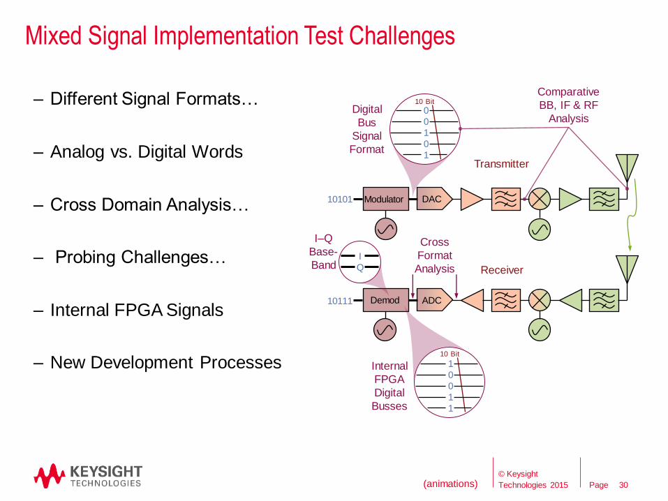
Mixed Signal Implementation Test Challenges
– Different Signal Formats…
– Analog vs. Digital Words
– Cross Domain Analysis…
– Probing Challenges…
– Internal FPGA Signals
– New Development Processes
Modulator
Demod
10101
10111
DAC
ADC
10 Bit
Internal
FPGA
Digital
Busses
1
0
0
1
1
Cross
Format
Analysis
Transmitter
Receiver
I
Q
I–Q
Base-
Band
0
0
1
0
1
Digital
Bus
Signal
Format
10 Bit
Comparative
BB, IF & RF
Analysis
30 (animations) © Keysight
Technologies 2015

Page 31
Use Same VSA Software Along a Mixed Signal Tx Chain with Instruments Appropriate for the Different Signal Formats
31
Logic
analyzer with
FPGA
dynamic
probe
and VSA
software
D/A PA FGPA/DSP
VSA software on
Oscilloscopes, RF
Signal Analyzers,
and Digitizers
IF RF Analog
(IF or IQ)
© Keysight
Technologies 2015

Page
Probing Across the DAC Boundary Using VSA Software with a Logic Analyzer (Digital) and Oscilloscope (Analog IF)
Logic analyzer on
left probing digital
signals on 21 FPGA
pins via flying leads
--- fed to VSA
Digital oscilloscope
on right probing
DAC analog output
IF --- fed to VSA
32
© Keysight
Technologies 2015 32
Page
Radar Target Simulation Requires Cost Effective Tools
33
© Keysight
Technologies 2015

Page
Radar Target Signal Simulation
To use an OTS signal generator for pulse Doppler radar target simulation, it must be made coherent with the radar under test This is difficult to achieve – no current OTS
signal generator can do this
Simulation systems for use with active and coherent radar systems are currently almost always based on digital RF memories (DRFM).
Passive, bistatic or multi-static radars that use non-coherent detection methods, also benefit from simulation tools based on commercial off-the-shelf (COTS) arbitrary waveform generators.
coherent pulse train
Passive radar antenna – Courtesy of Cassidian
© Keysight
Technologies 2015 34
Page
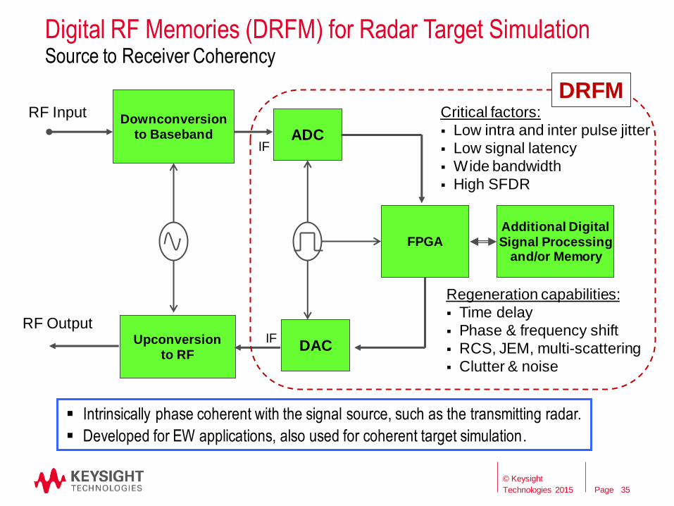
Digital RF Memories (DRFM) for Radar Target Simulation Source to Receiver Coherency
35
Intrinsically phase coherent with the signal source, such as the transmitting radar.
Developed for EW applications, also used for coherent target simulation.
Downconversion to Baseband ADC
RF Input
FPGA
DAC Upconversion
to RF
Additional Digital
Signal Processing and/or Memory
RF Output
Critical factors:
Low intra and inter pulse jitter
Low signal latency
Wide bandwidth
High SFDR
Regeneration capabilities:
Time delay
Phase & frequency shift
RCS, JEM, multi-scattering
Clutter & noise
DRFM
IF
IF
© Keysight
Technologies 2015

Page
Radar Cross Section (RCS)
The amplitude and phase of the radar return signal changes as the aspect angle of the target changes.
RCS is very dependent of the target size, shape and construction material.
Generalized RCS simulated using Swerling models (I – V) or for specific target RCS use recorded or customized signal returns.
© Keysight
Technologies 2015 36 36
Page
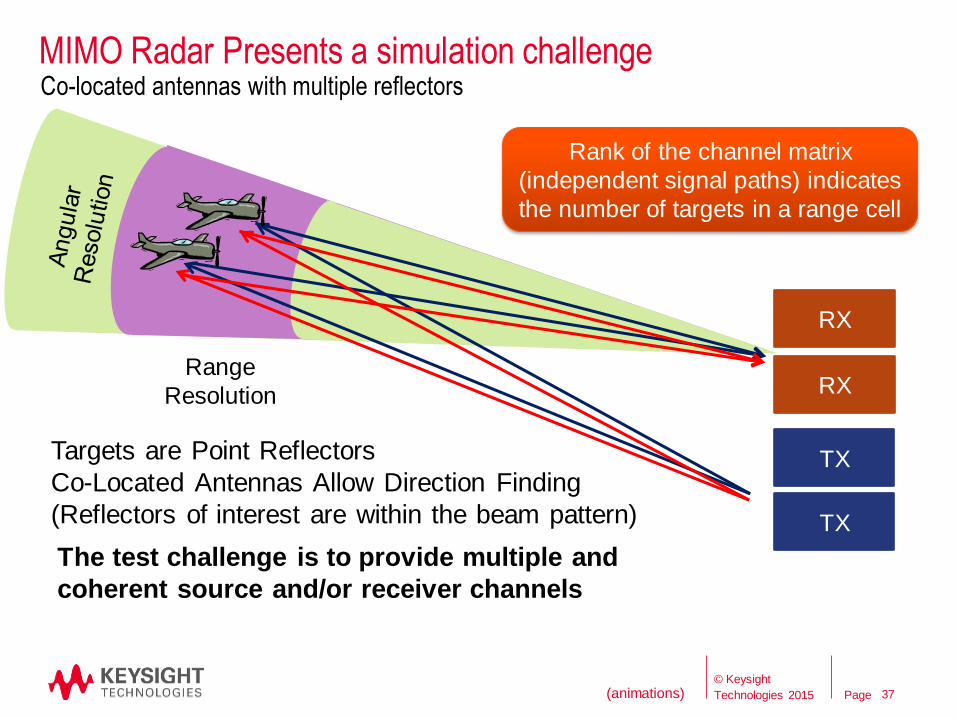
MIMO Radar Presents a simulation challenge
37
TX
TX
RX
RX
Co-located antennas with multiple reflectors
Targets are Point Reflectors
Co-Located Antennas Allow Direction Finding
(Reflectors of interest are within the beam pattern)
Rank of the channel matrix
(independent signal paths) indicates
the number of targets in a range cell
Range
Resolution
The test challenge is to provide multiple and
coherent source and/or receiver channels
37 (animations) © Keysight
Technologies 2015

Page
Concluding Remarks
38
© Keysight
Technologies 2015

Page
The Future for Test & Measurement
Test equipment needs to continuously adapt and improve to support
the use cases enabled by rapidly advancing technologies.
Components and systems; DC, digital, baseband & RF signals
Array antennas require multiple channels of stimulus and analysis
with wide bandwidth to gain measurement throughput .
Simulation of spectral environments which include a combination of
radar, wireless, wireless networking, and recorded signals require
streaming large amounts signal data.
Software defined instrumentation provides a method for controlling
test costs through hardware reuse and reduced time to first
measurement.
Keysight Technologies has the tools, support and commitment to
innovation needed to address the future of test.
Continuous Innovation
39
© Keysight
Technologies 2015
Page 40 Page 40
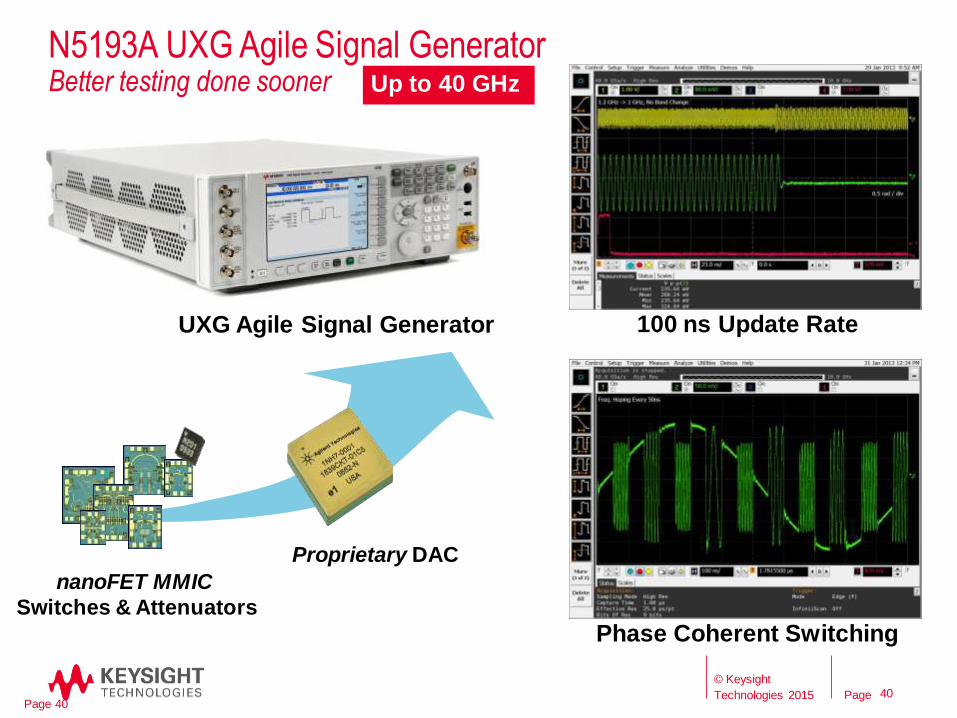
nanoFET MMIC
Switches & Attenuators
Proprietary DAC
100 ns Update Rate
Phase Coherent Switching
UXG Agile Signal Generator
N5193A UXG Agile Signal Generator Better testing done sooner
40
Up to 40 GHz
© Keysight
Technologies 2015
Page
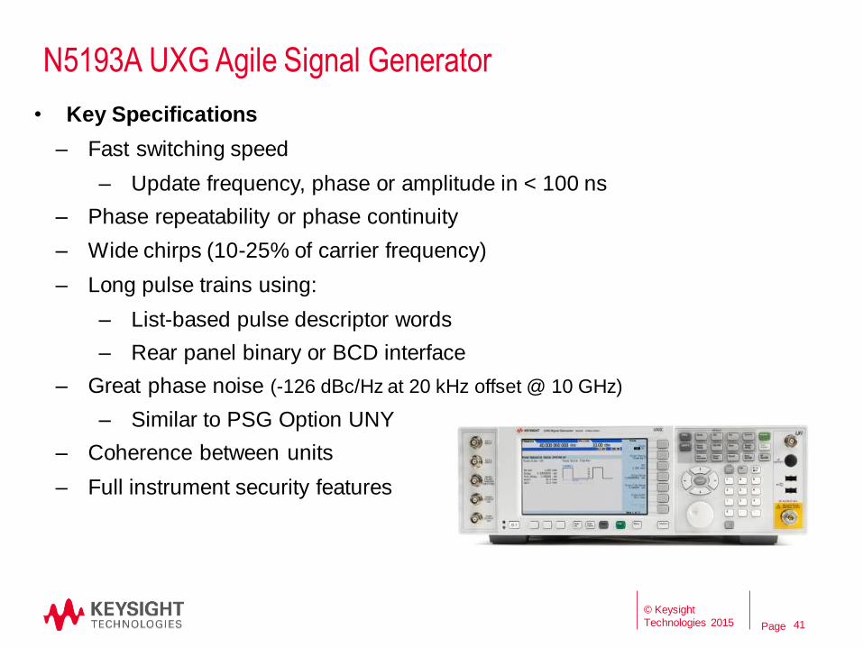
N5193A UXG Agile Signal Generator
• Key Specifications
– Fast switching speed
– Update frequency, phase or amplitude in < 100 ns
– Phase repeatability or phase continuity
– Wide chirps (10-25% of carrier frequency)
– Long pulse trains using:
– List-based pulse descriptor words
– Rear panel binary or BCD interface
– Great phase noise (-126 dBc/Hz at 20 kHz offset @ 10 GHz)
– Similar to PSG Option UNY
– Coherence between units
– Full instrument security features
41
© Keysight
Technologies 2015

Page Agilent Confidential
July 2014
N9040B UXA Signal Analyzer
Deeper views of elusive and wideband signals
8.4/13.6/26.5 GHz
Streamlined
touch driven
interface
Full BW RTSA
Up to 510 MHz
analysis BW
89600 VSA &
N9068C Phase
Noise App
Industry
Leading
Phase noise
42
© Keysight
Technologies 2015

Page
UXA – Advancing Technology to Deliver Performance
New proprietary ADC
2.4GSa/s 14 bit
New Wide BW Front End
510 MHz Analysis
Excellent RF flatness New Proprietary DAC
DDS based LO
Excellent Phase Noise
Low Spurious
New large touch-screen
display with modern GUI
Wideband Digital IF provides High Dynamic Range
510MHz BW
43
© Keysight
Technologies 2015

Page
M933xA
81180B
M8190A
M8195A
Proprietary Technology - Unique Performance
M9330A / N8241A
15 bit, 1.2 GSa/s
Best signal quality in PXI
and LXI from factor
81180B
12 Bit, 4.6 GSa/s 1 GHz analog BW
Economic version
M8190A
14 bit 8 GSa/s / 12 bit 12 GSa/s
5 GHz analog BW
Highest Dynamic Range
SFDR: -90 dBc .
10 dB more than the closest competitor
M8195A
65 GSa/s
20 GHz analog BW
Highest bandwidth and port
density in a 1U AXIe module
Jitter 5 ps pp @ 16Gb/s
SFDR: up to -80 dBc
Integrated FIR filter,
Hardware-encoding +
real-time impairments
Keysight High-Speed Arbitrary Waveform Generators
Choose the performance you need: High Resolution
Wide Bandwidth
44
© Keysight
Technologies 2015

Page
M8190A Arbitrary Waveform Generator - Overview
• Precision AWG with DAC resolution of:
• 14 bit up to 8 GSa/s
• 12 bit up to 12 GSa/s
• Up to 2 GSa Arbitrary Waveform Memory
per channel
• Up to 5 GHz bandwidth per channel
• 3 selectable output paths: direct DAC, DC
and AC
• SFDR: up to -90 dBc typ. (fout = 100 MHz, DC to 3
GHz)
• Harmonic distortion: -72 dBc typ. (fout = 100
MHz, balun)
• Advanced sequencing scenarios
sequences*)
• 2 markers per channel
45
© Keysight
Technologies 2015

Page
M8195A Arbitrary Waveform Generator - Overview
• 65 GSa/s on 1, 2 or 4 channels per module
• 20 GHz analog bandwidth
• 8 bit vertical resolution
• Up to 16 GSamples memory per module
• Sequencing capability
• Asynchronous trigger
• FIR filter per channel in hardware
• S-Parameter de-embedding
46
0
10
20
30
40
50
60
70
80
90
SFDR(dBc) vs. Tone freq. (MHz)
100 tones from 10 to 15 GHz with a notch @ 12.5 GHz
© Keysight
Technologies 2015

Page
Questions ?
47
© Keysight
Technologies 2015
Top Related