


Languages
Pages
Legal


1 Landis+Gyr Confidential - October 2011
Temperature Monitoring Hot SocketsIndustry Update / EEI PresentationOctober 2013

SENSITIVE UTILITY INFORMATION
This document provides sensitive information concerning a
utility’s practices. Landis+Gyr provides this document upon
request for utilities to facilitate thoughtful internal discussions
and to help utilities discuss hot-socket concerns with local fire
departments and answering media inquiries.
DO NOT provide this document directly to the public or media to
avoid the contents being misused or taken out of context.
Disclaimer
2 Landis+Gyr Confidential – 2013

+ Hot Socket Statistics
+ Causes of Hot Sockets
+ UL and ANSI C12.1 Meter Temperature Requirements
+ Temperature conditions within a meter under lab conditions
+ Temperature Monitoring Practices
Overview of Hot Sockets
3 Landis+Gyr Confidential – 2013

National Fire Prevention Association (NFPA)tracks sources of home electrical fires - 2013 report.
Electrical Fires Generally Decreasing
4 Landis+Gyr Confidential – 2013
No NFPA data 1999-2001
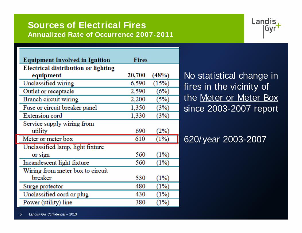
No statistical change in fires in the vicinity of the Meter or Meter Box since 2003-2007 report
620/year 2003-2007
Sources of Electrical FiresAnnualized Rate of Occurrence 2007-2011
5 Landis+Gyr Confidential – 2013

Approximately 135 million electric meters installed in the US
630 fires/year / 135m = 4.5 average per year over 1,000,000 meters
Taking into account wiring into/out of socket may increase the rate:
(690+610+530)/ 135m = 13.5 average per year over 1,000,000 meters
Electrical Fires Near the MeterAnnualized Rate of Occurrence 2007-2011
6 Landis+Gyr Confidential – 2013
What are likely socket concerns?
7
+ Sprung/damaged jaw
+ Loose wire termination at line or load side jaw
+ Meter blade beside and not into socket jaw
+ Worn line/load wire insulation arcing over to grounded mounting box
+ Total loads exceeding socket capacity – lots of older 100 amp services in the field
Landis+Gyr Confidential – 2013

Hot Socket Causes – Sprung Jaws
8 Landis+Gyr Confidential – 2013
Tin plating on jaw “cooked”
Heat accelerates oxidation on lug wire
Note: Tin Melts at 232ºC (450ºF)

“Bent Jaw” Connection (Continued)
9
Jaws are bent and do not meet parallel in the center.
Jaws appear bent down and splayed apart.
Good Jaws are almost parallel in the center, flat contact area.
This jaw/blade exhibited minimal if any thermal damage.
Landis+Gyr Confidential – 2013
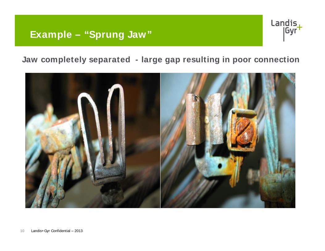
Example – “Sprung Jaw”
Jaw completely separated - large gap resulting in poor connection
10 Landis+Gyr Confidential – 2013
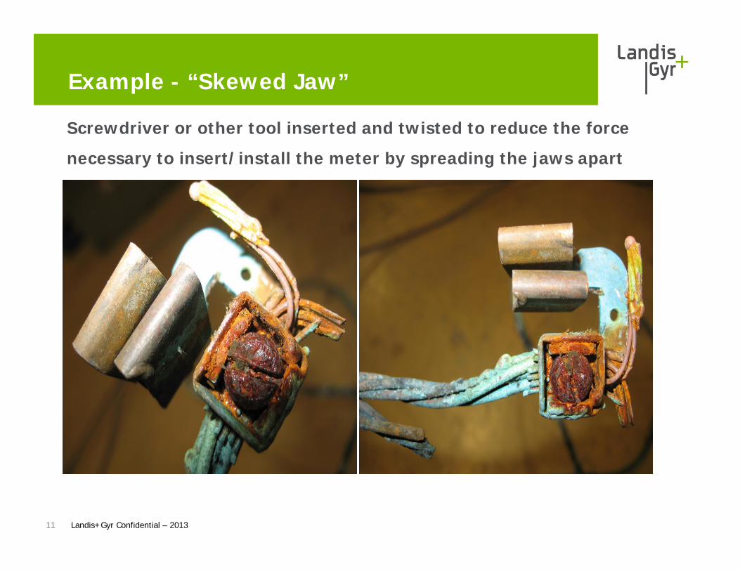
Example - “Skewed Jaw”
Screwdriver or other tool inserted and twisted to reduce the force
necessary to insert/install the meter by spreading the jaws apart
11 Landis+Gyr Confidential – 2013

Hot Socket – Sprung JawsLocalized Heating On Meter Blade
12 Landis+Gyr Confidential – 2013
Heat from poor jaw connection flows through meter blade.
FOCUS AL and FOCUS AX non-disconnect base plastic has 350ºC (660ºF) melting point.

Jaw to Blade Arcing
13
Jaws with intermittent connections will arc to the meter blade resulting in pitting on the blade.
Blade shows early signs of arcing.
Tin Melts at 232ºC which is lower than the 350ºC baseplate plastic.
Landis+Gyr Confidential – 2013

Severe Arcing Jaw to Blade
14 Landis+Gyr Confidential – 2013
Tin burned off
Blade hole due to arcing to jaw – Copper melts at 1040ºC (1900ºF)
AX-SD base thermoset plastic melts at 960ºC (1760ºF)
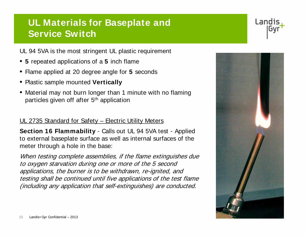
UL Materials for Baseplate and Service Switch
UL 94 5VA is the most stringent UL plastic requirement
• 5 repeated applications of a 5 inch flame
• Flame applied at 20 degree angle for 5 seconds
• Plastic sample mounted Vertically
• Material may not burn longer than 1 minute with no flaming particles given off after 5th application
UL 2735 Standard for Safety – Electric Utility Meters
Section 16 Flammability - Calls out UL 94 5VA test - Applied to external baseplate surface as well as internal surfaces of the meter through a hole in the base:
When testing complete assemblies, if the flame extinguishes due to oxygen starvation during one or more of the 5 second applications, the burner is to be withdrawn, re-ignited, and testing shall be continued until five applications of the test flame (including any application that self-extinguishes) are conducted.
15 Landis+Gyr Confidential – 2013

UL 2735 – Temperature Ratings at Maximum Current
16
For Comparison:ANSI C12.1 Test No. 9 Temperature Rise 55oC added to 40oC ambient = 90oC max
Landis+Gyr Confidential – 2013
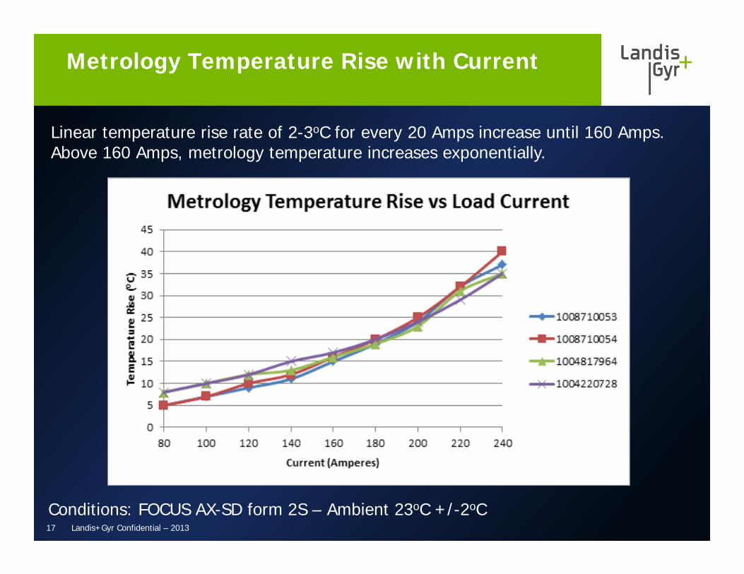
Linear temperature rise rate of 2-3oC for every 20 Amps increase until 160 Amps. Above 160 Amps, metrology temperature increases exponentially.
Metrology Temperature Rise with Current
17 Landis+Gyr Confidential – 2013
Conditions: FOCUS AX-SD form 2S – Ambient 23oC +/-2oC
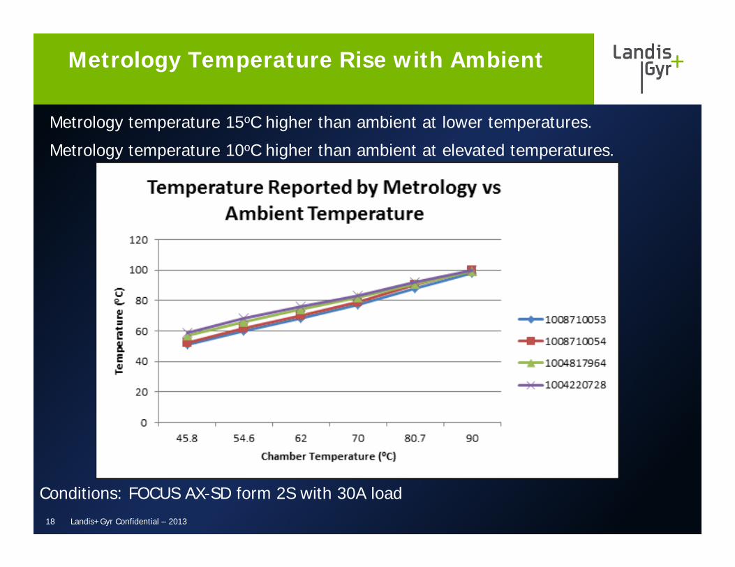
Metrology temperature 15oC higher than ambient at lower temperatures.
Metrology temperature 10oC higher than ambient at elevated temperatures.
Metrology Temperature Rise with Ambient
18 Landis+Gyr Confidential – 2013
Conditions: FOCUS AX-SD form 2S with 30A load

+ Modest temperature differences found between radios on FOCUS AX-SD (+/-5oC)
+ Metrology temperature is consistently higher than ambient, but the differential narrows to 10oC at elevated ambient temperatures which are of interest for “hot socket” detection.
+ Heat radiating off of the meter’s current coils increases under-cover temperatures exponentially as load current exceeds 160 Amps.
+ Heat due to a severe “hot socket” condition that can cause a melted baseplate will radiate through the meter’s current coils and cause an exponential temperature rise compared to ambient.
+ Many radio transmitters will thermally shut down at elevated temperatures in the 90-100oC range, however metrology will log the event for later reporting when radio has cooled off.
Summary of Meter Temperature Monitoring
19 Landis+Gyr Confidential – 2013
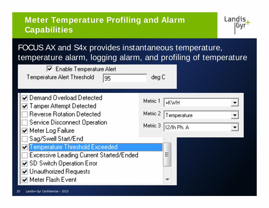
FOCUS AX and S4x provides instantaneous temperature, temperature alarm, logging alarm, and profiling of temperature
Meter Temperature Profiling and Alarm Capabilities
20 Landis+Gyr Confidential – 2013

+ Some utilities recording temperature in load profile on sample of meters to understand ambient conditions
+ If temperature threshold alert used – L+G recommends a value of 95-100oC depending on utility environmental conditions. Utility may choose to ignore events occurring during sunny parts of the day.
+ Some utilities taking temperature read coincident with current reading in middle of night
• Night time read has no solar heating to influence temperature read
• Night time typically has lower current (under 160 Amps) so load is less likely to cause false hot-socket events.
• Comparison of temperature extremes with respect to the average has good correlation – Benchmark average, review those that are 5-6oC degree’s above average (deviation) and assess for potential risk
Hot Socket Monitoring– Utility Best Practices
21 Landis+Gyr Confidential – 2013
+ Simulate hot socket conditions – Not an easy task. Many attempts have been made to simulate hot sockets
+ Once hot socket conditions can be simulated, monitor metrology temperature to confirm understanding and refine “best practice” recommendations
Future Areas of Research
22 Landis+Gyr Confidential – 2013
Questions?
Thank you
Top Related