


Languages
Pages
Legal


State of Tennessee Enhanced Elevation
Technical Specifications
FINAL DELIVERABLE
December 16, 2011
Produced by
With assistance from
For the
Department of Finance and Administration
Office for Information Resources
GIS Services

State of Tennessee Dept. of Finance & Administration Contract # 31701-03056 Applied Geographics, Inc
This document was produced for the State of Tennessee under Contract # 31701-03056,
With funding assistance from the Federal Geographic Data Committee (FGDC),
Under the Fifty States Initiative, Cooperative Agreements Program

State of Tennessee Dept. of Finance & Administration 2 Contract # 31701-03056 Applied Geographics, Inc
TABLE OF CONTENTS
Foreword and Acknowledgements .........................................................................................4
1 Introduction ....................................................................................................................5
2 Data Accuracy ..................................................................................................................7
2.1 Horizontal and Vertical Accuracy ........................................................................................ 8 2.2 Project Area and Tiling Scheme .......................................................................................... 9
3 Data Acquisition ............................................................................................................ 11
3.1 Description of Base Deliverables ...................................................................................... 12 3.2 Geodetic Datum, Coordinate Systems, and Units of Measure ......................................... 15 3.3 Acquisition Requirements ................................................................................................. 15 3.4 Geographic Coverage and Continuity ............................................................................... 16 3.5 LiDAR Mapping Survey Control ......................................................................................... 17
4 Standard Product Deliverables (Summary) ...................................................................... 19
4.1 Survey Report Metadata ................................................................................................... 19 4.2 Processing Report Metadata ............................................................................................ 19 4.3 Aircraft Trajectories Metadata ......................................................................................... 19 4.4 All Return Point Cloud ....................................................................................................... 19 4.5 Ground (Bare Earth) Surface Model Hydro-flattened and 3-D Breaklines ....................... 19 4.6 Microstation Points and Breakline File Requirements ..................................................... 20 4.7 Intensity Images ................................................................................................................ 20
5 Upgrade Product and Optional Services .......................................................................... 21
5.1 Upgrade Product – 9.25 cm RMSE FVA and 0.7 NPS ........................................................ 21 5.2 Contours (1 or 2 foot intervals (dependent upon standard or upgrade product), detailed
specifications issued with Task Order).............................................................................. 21 5.3 Hydro Enforced Bare Earth Elevation Model (50’ grid) .................................................... 22 5.4 Building Outlines ............................................................................................................... 22 5.5 Digital Surface Model ........................................................................................................ 22
6 Glossary of Terms .......................................................................................................... 23
7 Reference ...................................................................................................................... 27
TABLES AND FIGURES
Table 1. Quality Levels for Enhanced Elevation, U.S.G.S. National Enhanced Elevation Assessment, June 2011 ............................................................................................................. 8
Figure 1. Map Sheet Numbering Scheme ...................................................................................... 10
Table 2. Comparison of Tennessee LiDAR Project Specifications .................................................. 11

State of Tennessee Dept. of Finance & Administration 3 Contract # 31701-03056 Applied Geographics, Inc

State of Tennessee Dept. of Finance & Administration 4 Contract # 31701-03056 Applied Geographics, Inc
FOREWORD AND ACKNOWLEDGEMENTS
Through a grant awarded by the Federal Geographic Data Committee (FGDC) in March 2011, the OIR-GIS
has developed a business plan for enhanced elevation. A consulting team led by Applied Geographics,
Inc. with support from AECOM Technical Services, Inc. assisted OIR-GIS with development of the
business plan and with the development of these specifications. Over 160 members of the statewide
community engaged in five regional workshops and approximately 75 people participated in 20
interviews and provided input to the plan and specifications.
A steering committee guided the business planning process and its members were:
Brock Hill, Chairman Asst. Commissioner, Tennessee Dept. of Environment and Conservation
Dan Hawk Tennessee Economic and Community Development
Jim Waters Tennessee Dept. of Transportation - (Design Division)
Keith McFadden US Geological Survey
Jason Duke US Fish & Wildlife Service, Tennessee Geographic Information Council
Dave McMillen US Dept. of Agriculture, Natural Resource Conservation Service
Jennifer Higgs Nashville Metropolitan Planning Commission
In addition to the steering committee, members of the Enhanced Elevation Technical Committee,
representing several Federal agencies, State agencies, and local government, provided guidance and
feedback in the development of the Enhanced Elevation Technical Specifications.
Coincidental and complementary to the business plan project undertaken by OIR-GIS Services, was a
study by the US Geological Survey (USGS) for a National Enhanced Elevation Assessment (NEEA).
Reference material provided in interviews on the NEEA and USGS LiDAR specification (version 13) are
utilized in this document. Results of the NEEA are anticipated to be published in December 2011.
The specifications herein are an update to the previous Tennessee LiDAR Mapping Program Technical
Specification, originally issued on October 14, 2010 by OIR-GIS and the Tennessee Department of
Transportation.

State of Tennessee Dept. of Finance & Administration 5 Contract # 31701-03056 Applied Geographics, Inc
1 INTRODUCTION
The State of Tennessee seeks to create and acquire an enhanced elevation resource as part of the
Tennessee Base Mapping Program. The resource will meet the needs of many stakeholders for the
development of statewide flood risk maps and mitigation plans, emergency response, hydrologic and
watershed investigations, telecommunication planning and analysis, utilities and public works
improvements, aerial photo ortho-rectification, and other business functions that depend on high
accuracy measurement of topographic conditions.
The term enhanced elevation refers to precise 3-dimensional measurements of land or submerged
topography, built features, vegetation structure, and other landscape detail. LiDAR (Light Detection and
Ranging) technology will be used to create the enhanced elevation products under contract(s) with
qualified photogrammetric, engineering, and/or surveying firms.
Products derived from this specification will serve to supplement and enhance the existing GIS data
resources produced and sustained through the Tennessee Base Mapping Program (TNBMP), which was
initiated by the Comptroller of the Treasury, Division of Property Assessments in 1996. Program
management and GIS coordination functions were shifted to the Department of Finance and
Administration, Office for Information Resources, GIS Services (OIR-GIS) in 1998. The initial production
efforts of the TNBMP were completed in 2007. Maintenance responsibility for TNBMP GIS data is
assigned to OIR-GIS in partnership with other State agencies.
Floodplain mapping and related emergency response and mitigation planning is the predominant
business case and motivation for development of a statewide enhanced elevation resource. Through a
partnership with the Department of Economic and Community Development (ECD), OIR-GIS and ECD
have worked in support of FEMA’s Flood Map Modernization program. Now branded as Risk MAP, OIR-
GIS is continuing to work with FEMA through coordination and GIS training efforts in Tennessee to
increase public awareness of flood risk across the state. In 2012, this partnership has expanded, and
OIR-GIS is now identified by FEMA as a Cooperating Technical Partner (CTP). Together, OIR-GIS and
FEMA will strive to identify, procure, and collect the most accurate set of digital terrain data to support
Risk MAP and other needs for enhanced elevation data.

State of Tennessee Dept. of Finance & Administration 6 Contract # 31701-03056 Applied Geographics, Inc
The specifications herein support base deliverable products that meet or exceed minimum requirements
for flood risk mapping as published in Federal Emergency Management Agency’s Map Modernization –
Guidelines and Specifications for Flood Hazard Mapping Partners, Procedures Memorandum 61:
Standards for LiDAR and Other High Quality Digital Topography (2010). The standard products are
sufficiently accurate to generate the equivalent of 2’ contours traditionally used by local government.
An optional upgrade product is also part of this plan, and is suitable to generate the equivalent of 1’
contours. Together, the standard and upgrade products will serve many requirements of the statewide
geospatial community.

State of Tennessee Dept. of Finance & Administration 7 Contract # 31701-03056 Applied Geographics, Inc
2 DATA ACCURACY
All LiDAR data must meet or exceed the standard product specifications described in this document.
Stakeholder accuracy needs were assessed, in part, by using the chart provided in Table 1. Quality Levels
for Enhanced Elevation, U.S. Geological Survey National Enhanced Elevation Assessment, later in this
section. In the chart, a series of horizontal resolution and vertical accuracy ‘levels’ were provided to
help determine elevation accuracy needs for specific business functions of stakeholders. Quality Level 3
(QL3) in the chart was determined to be closest to the minimum level of elevation data required to
support the majority of stakeholder requirements, but not all. Flood risk mapping is the most
predominant business driver for creating an enhanced elevation resource, and the QL3 meets or
exceeds elevation specifications for most risk levels (highest excluded) per the Federal Emergency
Management Agency’s (FEMA) Guidelines and Specifications for Flood Hazard Mapping Partners,
Procedures Memorandum 61: Standards for LiDAR and Other High Quality Digital Topography, which is
available at the following URL: http://www.fema.gov/library/viewRecord.do?id=4345 .
In order to meet or exceed the specifications for all risk levels and overall program needs, the minimal
requirement for the TNBMP standard deliverable has a higher vertical accuracy requirement than the
USGS QL3, that is, 12.5 cm RMSE in open terrain (Fundamental Vertical Accuracy, FVA) with a nominal
pulse spacing (NPS) of 1.0 meters.

State of Tennessee Dept. of Finance & Administration 8 Contract # 31701-03056 Applied Geographics, Inc
Table 1. Quality Levels for Enhanced Elevation, U.S. Geological Survey
National Enhanced Elevation Assessment, June 2011
2.1 HORIZONTAL AND VERTICAL ACCURACY
For the standard product, bare-earth terrain data must be capable of supporting two-foot contour
accuracy. Vertical accuracy of the LiDAR data will be assessed and reported in accordance with
Guidelines for Digital Elevation Data, developed by the National Digital Elevation Program (NDEP) and
subsequently adopted by the American Society for Photogrammetry and Remote Sensing (APPRS). The
test for the vertical accuracy is conducted in five land cover categories: open terrain; high grass and
crops; brush and low trees; fully forested; and urban areas. Fundamental Vertical Accuracy (FVA) is
based entirely on the open terrain cover type; Consolidated Vertical Accuracy (CVA) includes
checkpoints from all cover types. Supplemental Vertical Accuracy (SVA) is reported separately on each
of the remaining four cover types. Additional information for the test are found in Section 1.5 Data
Quality of the Guidelines at www.ndep.gov/NDEP_Elevation_Guidelines_Ver1_10May2004.pdf .
State of Tennessee Dept. of Finance & Administration 9 Contract # 31701-03056 Applied Geographics, Inc
Standard product vertical accuracy requirements using the NDEP/ASPRS methodology are:
Fundamental Vertical Accuracy <= 24.5 cm ACCz, 95% (12.5cm RMSEz)
Consolidated Vertical Accuracy <= 36.3cm, 95th Percentile
Supplemental Vertical Accuracy <= 36.3cm, 95th Percentile
Horizontal accuracy shall be tested to meet or exceed an RMSE of one-half of the nominal pulse spacing
of the LiDAR data or 3 foot at the 95% confidence level for LiDAR data with nominal pulse spacing of 1.0
meters (using RMSE® x 1.7308 as defined by the FGDC Geospatial Positional Accuracy Standards, Part 3:
NSSDA).
2.2 PROJECT AREA AND TILING SCHEME
Tennessee OIR-GIS seeks sustainable funding source(s) to acquire seamless enhanced elevation
coverage across the state. Under a fully funded scenario, the program will likely acquire enhanced
elevation data in 4 annual increments by region. Regional boundaries for the project areas will be
coincident with county boundaries and/or the 8-digit hydrologic units as defined by USDA/USGS (HUC8).
The base tiling scheme for collection of LiDAR data products and flight mission planning will be the
County Index of Property Maps. The Comptroller of the Treasury, Division of Property Assessments
(DPA) developed a countywide index for each county in the state during the cadastral mapping program
in the 1960s. The county index is that portion of the Tennessee State Plane Coordinate grid that
overlaps the total area of the county. The individual grid cells in the county index have dimensions of
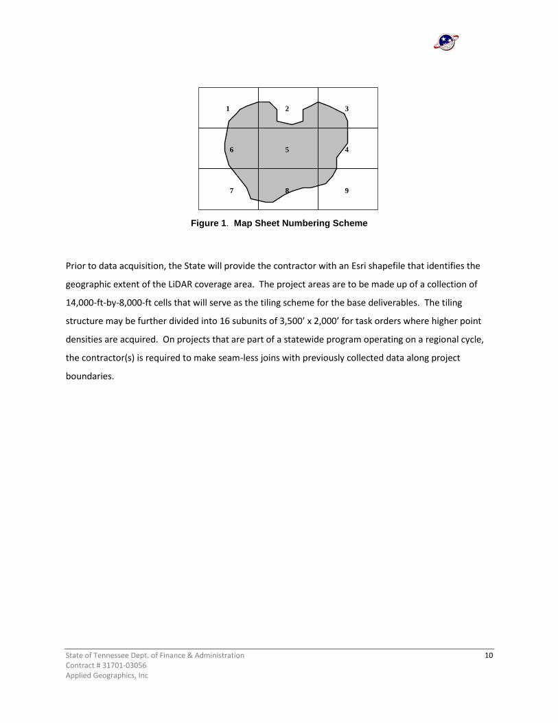
14,000 x 8,000 feet and are typically published at a map scale of 1”=400’. The numbering system usually
starts in the upper left portion of the county with map one and continues sequentially from top to
bottom until all grid cells that fall within the county are numbered (Figure 1). The total number of 1” =
400’ maps depends on the size of a county and usually range between 100 and 200 map sheets. The 1”=
400’ map sheets are the foundation of the Tennessee Base Mapping Program and are essential units for
developing and maintaining digital map data.
State of Tennessee Dept. of Finance & Administration 10 Contract # 31701-03056 Applied Geographics, Inc
Figure 1. Map Sheet Numbering Scheme
Prior to data acquisition, the State will provide the contractor with an Esri shapefile that identifies the
geographic extent of the LiDAR coverage area. The project areas are to be made up of a collection of
14,000-ft-by-8,000-ft cells that will serve as the tiling scheme for the base deliverables. The tiling
structure may be further divided into 16 subunits of 3,500’ x 2,000’ for task orders where higher point
densities are acquired. On projects that are part of a statewide program operating on a regional cycle,
the contractor(s) is required to make seam-less joins with previously collected data along project
boundaries.
1
4 5 6
7 8 9
2 3
State of Tennessee Dept. of Finance & Administration 11 Contract # 31701-03056 Applied Geographics, Inc
3 DATA ACQUISITION
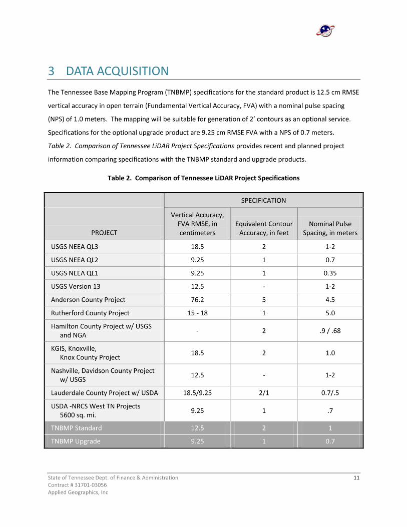
The Tennessee Base Mapping Program (TNBMP) specifications for the standard product is 12.5 cm RMSE
vertical accuracy in open terrain (Fundamental Vertical Accuracy, FVA) with a nominal pulse spacing
(NPS) of 1.0 meters. The mapping will be suitable for generation of 2’ contours as an optional service.
Specifications for the optional upgrade product are 9.25 cm RMSE FVA with a NPS of 0.7 meters.
Table 2. Comparison of Tennessee LiDAR Project Specifications provides recent and planned project
information comparing specifications with the TNBMP standard and upgrade products.
Table 2. Comparison of Tennessee LiDAR Project Specifications
SPECIFICATION
PROJECT
Vertical Accuracy, FVA RMSE, in centimeters
Equivalent Contour Accuracy, in feet
Nominal Pulse Spacing, in meters
USGS NEEA QL3 18.5 2 1-2
USGS NEEA QL2 9.25 1 0.7
USGS NEEA QL1 9.25 1 0.35
USGS Version 13 12.5 - 1-2
Anderson County Project 76.2 5 4.5
Rutherford County Project 15 - 18 1 5.0
Hamilton County Project w/ USGS and NGA
- 2 .9 / .68
KGIS, Knoxville, Knox County Project
18.5 2 1.0
Nashville, Davidson County Project w/ USGS
12.5 - 1-2
Lauderdale County Project w/ USDA 18.5/9.25 2/1 0.7/.5
USDA -NRCS West TN Projects 5600 sq. mi.
9.25 1 .7
TNBMP Standard 12.5 2 1
TNBMP Upgrade 9.25 1 0.7
State of Tennessee Dept. of Finance & Administration 12 Contract # 31701-03056 Applied Geographics, Inc
3.1 DESCRIPTION OF BASE DELIVERABLES
Point Cloud
Contractor(s) is to deliver an unclassified LiDAR point cloud (LAS 1.2) in the compressed .laz format (one
file per swath), for the coverage area specified in each RFQ/task order. Sensors should include
capabilities to collect up to 3 or more multiple discrete returns including the first and last returns. In
addition to the return values, the intensity value for each pulse shall be included. Point cloud data shall
include GPS time, intensity data, and the headers shall include the date of collection. Data voids and
gaps in the LiDAR point cloud are unacceptable, except over water surfaces and fresh asphalt.
Contractor(s) is to also deliver a classified LiDAR point cloud (LAS 1.2) in the compressed .laz format.
All LiDAR points must be classified according to American Society of Photogrammetry and Remote
Sensing (ASPRS) guidelines and stored in LAS format for easy retrieval and usability.
ASPRS minimum classifications should be:
Unclassified (non-ground) – Class 1
Ground (bare-earth extra points) – Class 2
Noise – Class 7
Model Key Point (thinned bare-earth) – Class 8
Water – Class 9
Overlap Points (overlap from adjoining flight lines) – Class 12
Bridge Deck Points – Class 13
Additional elements of the classified LiDAR point cloud deliverable:
A complete LiDAR point cloud shall be delivered where the bare earth classification (Class 2) is
free of features not representing the earth's surface (e.g. cell towers, building, trees, vehicles,
etc.). These features shall be classified as Class 1.
LiDAR points inside of water bodies will be classified as water Class 9. Water bodies are defined
as standing water bodies => 1 acre and streams or rivers => 50 feet.
State of Tennessee Dept. of Finance & Administration 13 Contract # 31701-03056 Applied Geographics, Inc
The model key, which is a subset of the bare earth point which represents a critical abrupt
change in the terrain slope, should be classified as Class 8.
Class 12 will be used for LiDAR points in areas of overlapping flight lines, which have been
deliberately deleted and removed from point cloud because of their reduced accuracy, possibly
due to their off-nadir position.
All noise and blunder points shall be classified as Class 7.
Public header information must be contained as specified within the LAS 1.2 file specification. In
addition to the LAS 1.2 required fields, the following items are required to be populated:
o Project ID – GUID data 1: project identifier
o File Creation Day of Year: 1
o File Creation Year: year created
The fields File Creation Day of Year and File Creation Year are the file creation date. This date
will represent the day the final LAS file is generated for submittal.
Projection information for the point data must be specified in the Variable Length Records using
the GeoTIFF specification as the model, as defined in the LAS 1.2 file specification.
The Point Data Record Format shall follow the Point Data Record Format 1, as defined in the LAS
1.2 Specification. In addition to the required items, the intensity shall be populated.
Class 13 will be used for LiDAR point returns on bridge decks with a minimum bridge length of
40 feet. Points should be representative of only the bridge deck free of obstructions such as
overhanging vegetation, automobiles, etc.
Digital Elevation Model (base earth)
Contractor(s) is to deliver a Digital Elevation Model (DEM) of bare earth conditions with 5 foot grid
cells. The DEM is to be hydro flattened using 3-D breaklines. Any raw data or extraneous values are to
be processed to provide ground-level, surface elevations or “bare-earth” DEMs devoid of vegetation or
man-made structures. The hydro flattening term is relatively new and recently coined by the US
State of Tennessee Dept. of Finance & Administration 14 Contract # 31701-03056 Applied Geographics, Inc
Geological Survey for integration of DEMs into the National Elevation Dataset (NED). DEMs intended
for incorporation into the National Elevation Dataset must be hydro flattened. Hydro flattening refers to
the process of ‘flattening’ water bodies in the DEM with further definition offered in USGS NGP LiDAR
Guidelines and Base Specification February 22, 2010 Version 13 – ILMF 2010. Hydro flattening is not to
be confused with ‘hydro conditioning’ and ‘hydro enforcement’, which involve processing to remove
unintended sinks in the surface model and additional flow considerations to support engineering
studies.
Hydro flattening of Inland Ponds and Lakes:
1-acre or greater surface area at the time of collection. Flat and level water bodies (single
elevation for every bank vertex defining a given water body). The entire water surface edge
must be at or below the immediately surrounding terrain. Long impoundments such as
reservoirs, inlets, and fjords, whose water surface elevations drop when moving downstream,
should be treated as rivers.
Hydro flattening of Inland Streams and Rivers:
50’ nominal width. This should not unnecessarily break a stream or river into multiple segments.
At times it may squeeze slightly below 50’ for short segments. Data producers should use their
best professional judgment. Flat and level bank-to-bank (perpendicular to the apparent flow
centerline); gradient to follow the immediately surrounding terrain. The entire water surface
edge must be at or below the immediately surrounding terrain. Streams channels should break
at road crossings (culvert locations). These road fills should not be removed from DEM.
However, streams and rivers should not break at elevated bridges. Bridges should be removed
from DEM. When the identification of a feature as a bridge or culvert cannot be made reliably,
the feature should be regarded as a culvert.
3-D Breaklines
Contractor(s) is to deliver the 3-D breaklines used to hydro-flatten the DEM. All breaklines developed
for use in hydro-flattening shall be delivered as an Esri feature class (PolylineZ or PolygonZ), and
geodatabase format is preferred over Esri shapefile. Each feature class or shapefile will include properly
State of Tennessee Dept. of Finance & Administration 15 Contract # 31701-03056 Applied Geographics, Inc
formatted and accurate georeference information in the standard location. All shapefiles must include
the companion.prj file.
Breaklines must use the same coordinate reference system (horizontal and vertical) and units as the
LiDAR point cloud delivery, identified in section 3.2 as the Tennessee State Plane (FIPS Zone 4100).
Breakline delivery will be in tiles and features must edge-match seamlessly in both the horizontal and
vertical.
Intensity Images
Contractor(s) is to deliver a raster image of the intensity measurements for 1st return data. The
intensity image will be provided as 5 foot grid and tiled to the format described in Section 2.2, and
delivered in GeoTIFF format. Projection and coordinate systems to be compatible with base deliverables
as referenced in Section 3.2.
Project Metadata
Federal Geographic Data Committee compliant metadata, project and group level.
3.2 GEODETIC DATUM, COORDINATE SYSTEMS, AND UNITS OF MEASURE
The survey should be performed as follows:
Horizontal coordinates shall be U.S. Survey Foot to at least two decimal places, Tennessee State
Plane (FIPS Zone 4100) coordinate system.
Horizontal datum shall be referenced to the North American Datum of 1983, North American
Plate National Adjustment of 2011, otherwise referred to as NAD 83 (2011).
Elevations shall be U.S. Survey Foot to at least two decimal places, vertical datum shall be
referenced to the North American Vertical Datum of 1988 (NAVD 88-Geoid12).
GPS surveys will be tied to the NAD 83 (2011), including TDOT GNSS Reference Network
stations.
3.3 ACQUISITION REQUIREMENTS
Cloud and fog-free between aircraft and ground.

State of Tennessee Dept. of Finance & Administration 16 Contract # 31701-03056 Applied Geographics, Inc
Ground to be free of snow and no unusual flooding or inundation, unless requirement is waived
in advance.
LiDAR sensor shall be capable of recording up to 3 (or more) returns per pulse, including 1st and
last returns.
Scan Angle of LiDAR sensor must be less than +/- 30 degrees off nadir.
Swath Overlap: Nominal sidelap on adjoining swaths shall be 30% coverage.
GPS Procedures: At least two TDOT GNSS Reference Network stations in operation during all
missions with baseline distances for GPS ground control not to exceed 50 miles.
Data Collection Season: During leaf-off season - late fall and winter (depending on area of
State), usually between early December and late March, unless otherwise agreed upon.
Project level metadata are required for LAS (point cloud) data that fully comply with Federal
Geographic Data Committee (FGDC) metadata standards.
LAS delivery tile size will 14,000 foot x 8,000 foot cells subject to further sub-tiling with higher
resolution collections. See (Sec 2.2).
Delivery will be completed by county or region, depending on the task order.
Contractor shall ensure that all parts of the county or region specified in the task order are fully
covered. No portion of the project area is to be omitted from collection and processing.
Data gaps between adjacent flight lines are not acceptable.
No data voids due to system malfunctions or lack of overlap.
3.4 GEOGRAPHIC COVERAGE AND CONTINUITY
Tennessee OIR-GIS intends to provide statewide seamless coverage of enhanced elevation
encompassing the entire State of Tennessee. A potential to extend the coverage into adjoining states
to allow coverage of complete hydrologic units may exist. When the program becomes fully funded, an
acquisition schedule will be determined and publicized. A popular scenario which has been discussed
among stakeholders is to develop a regional acquisition schedule, where one-third or one-fourth of the
State of Tennessee Dept. of Finance & Administration 17 Contract # 31701-03056 Applied Geographics, Inc
state is acquired on a 3 or 4 year cycle. There is no guarantee of funding to support this approach, and a
less aggressive, scaled back approach may be required due to economic conditions.
3.5 LIDAR MAPPING SURVEY CONTROL
For the standard product at 12.5 cm RMSE vertical accuracy (FVA) with 1.0 meter LiDAR pulse
spacing, the vertical ground control must be accurate to 4 cm RMSE.
Density and distribution of the ground control should ensure accuracy of the final deliverables.
A survey report that documents and certifies the procedures and accuracies of the horizontal
and vertical control, aircraft positioning systems, and system calibration procedures used in the
LiDAR mapping project shall be created.
The horizontal and vertical control shall be based on direct ties to National Geodetic Survey
(NGS) control stations, National Spatial Reference System (NSRS). All geodetic control surveys,
both horizontal and vertical, shall conform to the Standards and Specifications for Geodetic
Control Networks (1984), Federal Geodetic Control Committee (FGCC).
o The horizontal control shall reference the NAD 83 (2011). Procedures used to establish
horizontal photogrammetric ground control using GPS measurements shall meet or exceed
Second Order Horizontal Control as set forth by the FGCC, Geometric Geodetic Accuracy
Standards and Specifications for using GPS Relative Positioning Techniques, Version 5.0, May
1988.
o The vertical control shall reference the North American Vertical Datum of 1988 (NAVD88)
using Geoid12 to perform conversions from ellipsoidal heights to orthometric heights.
Procedures used to establish vertical control shall meet or exceed Third Order Vertical
Control Accuracy Standards and Specifications. Procedures for GPS-Derived elevation
differences shall meet or exceed Guidelines for Establishing GPS-Derived Ellipsoid Heights
(Standards: 2 cm and 5 cm), NGS-58, November 1997, and/or Guidelines for Establishing
GPS-Derived Orthometric Heights (Standards: 2 cm and 5 cm), NGS-59, October 2005.

State of Tennessee Dept. of Finance & Administration 18 Contract # 31701-03056 Applied Geographics, Inc
o A text report that describes the survey methods, results and contractor accuracy
assessments, including internal consistency and absolute accuracy, file formats, file naming
schemes, and tiling schemes.
State of Tennessee Dept. of Finance & Administration 19 Contract # 31701-03056 Applied Geographics, Inc
4 STANDARD PRODUCT DELIVERABLES (SUMMARY)
4.1 SURVEY REPORT METADATA
Detail the collection of control and reference points used for calibration and QA/QC
4.2 PROCESSING REPORT METADATA
Detail calibration, classification, and product generation procedures including methods used for
breakline collection and hydro flattening
4.3 AIRCRAFT TRAJECTORIES METADATA
The actual trajectory of the acquisition is to be provided in Esri shapefile format with all necessary
attributes, at minimum, flightline name, beginning and ending timestamps
4.4 ALL RETURN POINT CLOUD
a. Unclassified all return point cloud in LAS 1.2 (compressed .laz) format. FGDC compliant group
level metadata.
b. Classified all return point cloud in LAS 1.2 (compressed .laz) format. FGDC compliant group
level metadata.
4.5 GROUND (BARE EARTH) SURFACE MODEL HYDRO-FLATTENED AND 3-D BREAKLINES
a. Digital elevation model (DEM) of ground surface (5 foot grid), hydro flattened with 3-D
breaklines. Surface Models shall have no tiling artifacts, no gaps and no artificial smoothing at
tile boundaries
File format in Esri GRID. FGDC compliant group level metadata.
b. 3-D breaklines suitable to support hydro-flattening as an Esri geodatabase. FGDC compliant
group level metadata.

State of Tennessee Dept. of Finance & Administration 20 Contract # 31701-03056 Applied Geographics, Inc
4.6 MICROSTATION POINTS AND BREAKLINE FILE REQUIREMENTS
a. A ground (bare earth) MicroStation 3-D graphic *.dgn file will be required that contains LAS
class 8 model key points and breaklines. The level and symbology of these graphic elements
shall follow the values defined in the standard level structure found in document file
CADDV8.pdf available at
http://www.tdot.state.tn.us/Chief_Engineer/assistant_engineer_design/
design/v8/v8design.htm.
b. A bridge decks MicroStation 3-D graphic *.dgn file will be required that contains LAS class 13
bridge deck points and breaklines of bridge decks. The level and symbology of these graphic
elements shall follow the values defined in the standard level structure found in document
file CADDV8.pdf at the same link provided in 4.6.a above. All bridges greater than the
minimum length of 40 feet shall be included in this *.dgn file.
4.7 INTENSITY IMAGES
Raster intensity image of first returns in GeoTIFF format, 5 foot pixel size tiled (14,000 x 8,000 feet).
FGDC compliant group level metadata.

State of Tennessee Dept. of Finance & Administration 21 Contract # 31701-03056 Applied Geographics, Inc
5 UPGRADE PRODUCT AND OPTIONAL SERVICES
5.1 UPGRADE PRODUCT – 9.25 CM RMSE FVA AND 0.7 NPS
The Tennessee Base Mapping Program enhanced elevation specification for the upgrade
product requires a vertical accuracy of 9.25 cm RMSE for FVA with nominal pulse spacing of
0.7m and is suitable to generate a contour equivalent of 1 foot. The vertical accuracy testing
requirements using the NDEP/ASPRS guidelines and methodology are:
Fundamental Vertical Accuracy <= 18.2 cm ACCz, 95% (9.25 cm RMSEz)
Consolidated Vertical Accuracy <= 27.3 cm, 95th Percentile
Supplemental Vertical Accuracy <= 27.3 cm, 95th Percentile
Horizontal accuracy shall be tested to meet or exceed an RMSE of one-half of the nominal pulse
spacing of the LiDAR data or 3-foot at the 95% confidence level for LiDAR data with nominal
pulse spacing of 0.7 meters (using RMSE® x 1.7308 as defined by the FGDC Geospatial
Positional Accuracy Standards, Part 3: NSSDA).
For the upgrade product at 9.25 cm RMSE vertical accuracy (FVA) with 0.7 meter LiDAR pulse
spacing, the vertical ground control must be accurate to 3 cm RMSE.
5.2 CONTOURS (1 OR 2 FOOT INTERVALS (DEPENDENT UPON STANDARD OR UPGRADE PRODUCT), DETAILED SPECIFICATIONS ISSUED WITH TASK ORDER)
Contour Level 3 (CL3): Typically auto-generated, moderately aesthetic and consistent with an
acceptable level of smoothing.
Contour Level 2 (CL2): Typically auto-generated with some manual enhancements, aesthetically
pleasing with acceptable cartographic style.
Contour Level 1 (CL1): High quality cartographic style with high end smoothing, full attribution of
index contours, depressions, sinks.
State of Tennessee Dept. of Finance & Administration 22 Contract # 31701-03056 Applied Geographics, Inc
5.3 HYDRO ENFORCED BARE EARTH ELEVATION MODEL (50’ GRID)
The manual stereo compilation of 3D breaklines using stereo pairs generated from LiDAR
intensity and surface is required to generate this product. The stereo pairs should be generated
at a GSD that does not exceed the nominal LiDAR pulse spacing. Breaklines specified in the base
product deliverables do not support Hydro enforcement.
5.4 BUILDING OUTLINES
All visible freestanding structures shall be collected and included as topologically correct
polygon features. The minimum structure that is to be collected from the LiDAR intensity
images shall be 1000 square feet. The building footprint is acceptable for depicting the building
outline. Buildings to be delivered as an Esri geodatabase feature class.
5.5 DIGITAL SURFACE MODEL
An elevation model created to depict the elevations of the top surfaces of buildings, trees,
towers, and other features elevated above the bare earth

State of Tennessee Dept. of Finance & Administration 23 Contract # 31701-03056 Applied Geographics, Inc
6 GLOSSARY OF TERMS
BARE EARTH TERRAIN - Digital elevation data of the terrain, free from vegetation, buildings, and other
man-made structures. Elevations of the ground are derived from pulse-processing of LiDAR data.
Automated and manual pulse-processing routines are used to eliminate points that impinge on
elevation features.
BREAKLINE – A linear feature demarking a change in the smoothness or continuity of a surface such as
abrupt elevation changes or a stream line.
CONSOLIDATED VERTICAL ACCURACY (CVA) – The result of a test of the accuracy of vertical checkpoints
(z-values) consolidated for two or more of the major land cover categories, representing both open
terrain and other land cover categories. Computed by using the 95th percentile, CVA is always
accompanied by Fundamental Vertical Accuracy (FVA).
DIGITAL ELEVATION MODEL (DEM) - A popular acronym used as a generic term for digital topographic
and/or bathymetric data in all its various forms, but most often bare earth elevations at regularly spaced
intervals in x and y directions. Regularly spaced elevation data are easily and efficiently processed in a
variety of computer uses. A digital elevation model (DEM) contains elevations at points arranged in a
raster data structure, a regularly spaced x, y grid, where the intervals of Δx and Δy are normally in linear
units (feet or meters) or geographic units (degrees or fractions of degrees of latitude or longitude). The
z-values in a DEM represent the height of the terrain, relative to a specific vertical datum and void of
vegetation or manmade structures such as buildings, bridges, walls, et cetera. The elevation of lakes and
rivers in a DEM implies the height of the water surface based on elevation of the exposed shoreline. The
observations, or direct measurements, of elevation that comprise the DEM are almost never actually
captured on a regular grid; therefore, the elevation for any given point in the grid is normally
interpolated from other forms of source data. LiDAR, for example, yields a dense set of irregularly
spaced points; interpolation to a grid requires using one of many possible interpolation algorithms,
which produce varying results. Linear features, such as streams, drainage ditches, ridges, and roads are
often lost in a DEM if the grid spacing is larger than the dimensions of the feature. Furthermore, in a
DEM, it is unlikely that the sharp edge of the feature will be represented correctly in the terrain model.
State of Tennessee Dept. of Finance & Administration 24 Contract # 31701-03056 Applied Geographics, Inc
The DEM, because it is a raster data structure similar to a digital image, is an efficient format for storage,
analysis, rendering, and visualization.
DIGITAL SURFACE MODEL (DSM) – An elevation model created for use in computer software that is
similar to DEMs or DTMs except that DSMs depict the elevations of the top surfaces of buildings, trees,
towers, and other features elevated above the bare earth.
ENHANCED ELEVATION - Precise 3-D measurements of land or submerged topography, built features,
vegetation structure, and other landscape detail.
FUNDAMENTAL VERTICAL ACCURACY (FVA) – The value by which vertical accuracy can be equitably
assessed and compared among datasets. The FVA is determined with vertical checkpoints located only
in open terrain, where there is a very high probability that the sensor will have detected the ground
surface. FVA is calculated at the 95% confidence level in open terrain only, using RMSEz x 1.9600.
HILLSHADE - A function used to create an illuminated representation of a surface, using a hypothetical
light source that simulates the cast shadow thrown upon a raised relief map. This process is helpful in
identifying linear features such as streams and ridgelines.
HYDROLOGICALLY-ENFORCED (Hydro-Enforced) – Processing of mapped water bodies so that lakes and
reservoirs are level and so that streams flow downhill. For example, a DEM, TIN or topographic contour
dataset with elevations removed from the tops of selected drainage structures (bridges and culverts) so
as to depict the terrain under those structures. Hydro-enforcement enables hydrologic and hydraulic
models to depict water flowing under these structures, rather than appearing in the computer model to
be dammed by them because of road deck elevations higher than the water levels. Hydro-enforced TINs
also utilize breaklines along shorelines and stream centerlines, for example, where these breaklines
form the edges of TIN triangles along the alignment of drainage features. Shore breaklines for streams
would be 3-D breaklines with elevations that decrease as the stream flows downstream; however, shore
breaklines for lakes or reservoirs would have the same elevation for the entire shoreline if the water
surface is known or assumed to be level throughout.
LAS - The ASPRS LAS file format is a public file format for the interchange of 3-dimensional point cloud
data between data users. Although developed primarily for exchange of LiDAR point cloud data, this

State of Tennessee Dept. of Finance & Administration 25 Contract # 31701-03056 Applied Geographics, Inc
format supports the exchange of any 3-dimensional x-y-z tuplet. This binary file format is an alternative
to proprietary systems or a generic ASCII file interchange system used by many companies.
LiDAR - is an acronym for Light Detection and Ranging. LiDAR is synonymous with airborne laser
mapping and laser altimetry. A LiDAR sensor is an instrument that measures distance to a reflecting
object by emitting timed pulses of laser light and measuring the time between emission and reception
of reflected pulses. The measured time interval is converted to distance.
NATIONAL DIGITAL ELEVATION PROGRAM - With an ever growing demand for digital elevation data by
Federal, state, and local governments, the National Digital Elevation Program (NDEP) was established to
promote the exchange of digital elevation data among government, private, and nonprofit sectors and
the academic community, and to establish standards and guidance that will benefit all users. The NDEP
currently consists of representatives from approximately 12 federal agencies and the National States
Geographic Information Council (NSGIC).
NOMINAL PULSE SPACING (NPS) – The estimated average spacing of irregularly-spaced LiDAR points in
both the along-track and cross-track directions resulting from: the laser pulse repetition frequency (e.g.,
100,000 pulses of laser energy emitted in one second from a 100 kHz sensor); scan rate (sometimes
viewed as the number of zigzags per second for this common scanning pattern); field-of-view; and flight
airspeed. LiDAR system developers currently provide “design NPS” as part of the design pulse density,
although the American Society for Photogrammetry and Remote Sensing (ASPRS) is currently developing
standard procedures to compute the “empirical NPS” which should be approximately the same as the
“design NPS” when accepting statistically insignificant loss of returns and disregarding void areas, from
water for example. The NPS assessment is made against single swath first return data located within the
geometrically usable center portion (typically ~90%) of each swath. Average along-track and cross-track
pulse spacing should be comparable. When point density is increased by relying on overlap or double-
coverage it should be documented in metadata, and the project’s reported NPS should not change. The
NPS should be equal to or less than the Digital Elevation Model.
POINT CLOUD - Often referred to as the “raw point cloud”, this is the first data product of a LiDAR
instrument. In its crudest form, a LiDAR raw point cloud is a collection of range measurements and
sensor orientation parameters. After initial processing, the range and orientation of each laser value is
converted to a position in a three dimensional frame of reference and this spatially coherent cloud of

State of Tennessee Dept. of Finance & Administration 26 Contract # 31701-03056 Applied Geographics, Inc
points is the base for further processing and analysis. The raw point cloud typically includes first, last,
and intermediate returns for each laser pulse. In addition to spatial information, LiDAR intensity returns
provide texture or color information. The combination of three dimensional spatial information and
spectral information contained in the LiDAR dataset allows great flexibility for data manipulation and
extraction.
ROOT MEAN SQUARE ERROR (RMSE) – The square root of the average of the set of squared differences
between dataset coordinate values and coordinate values from an independent source of higher
accuracy for identical points. The vertical RMSE (RMSEz), for example, is calculated as the square root of
S(Zn –Z’n)2/N, where: Zn is the set of N z-values (elevations) being evaluated, normally interpolated (for
TINs and DEMs) from dataset elevations of points surrounding the x/y coordinates of checkpointsZ’n is
the corresponding set of checkpoint elevations for the points being evaluated N is the number of
checkpoints n is the identification number of each of the checkpoints from 1 through N.
SUPPLEMENTAL VERTICAL ACCURACY (SVA) – The result of a test of the accuracy of z-values over areas
with ground cover categories or combination of categories other than open terrain. Computed by using
the 95th percentile, SVA is always accompanied by Fundamental Vertical Accuracy (FVA). SVA values are
computed individually for different land cover categories. Each land cover type representing 10% or
more of the total project area is typically tested and reported as an SVA. SVA specifications are normally
target values that may be exceeded so long as overall CVA requirements are satisfied.

State of Tennessee Dept. of Finance & Administration 27 Contract # 31701-03056 Applied Geographics, Inc
7 REFERENCE
Federal Emergency Management Agency’s (FEMA) Guidelines and Specifications for Flood Hazard
Mapping Partners, Procedures Memorandum 61: Standards for LiDAR and Other High Quality Digital
Topography (September 2010). See www.fema.gov/library/viewRecord.do?id=4345, accessed on
12/11/2011.
Federal Geographic Data Committee, FGDC Geospatial Positional Accuracy Standards, Part 3:
NSSDA, 1998.
Maune, D.F., 2007. Definitions, in Digital Elevation Model Technologies and Applications: The DEM Users
Manual, 2nd Edition (D.F. Maune, editor), American Society for Photogrammetry and Remote Sensing,
Bethesda, MD pp. 550-551.
National Digital Elevation Program, Guidelines for Digital Elevation Data, Version 1, 2004
http://www.ndep.gov/NDEP_Elevation_Guidelines_Ver1_10May2004.pdf, accessed on 12/11/2011.
State of Tennessee, Department of Transportation - Design Division, CADD Standards and Downloads
http://www.tdot.state.tn.us/Chief_Engineer/assistant_engineer_design/design/v8/v8design.htm,
accessed on 12/11/2011.
State of Tennessee, Office of Information Resources – GIS Services, Tennessee LiDAR Mapping Program
Technical Specification, October 14, 2010.
State of Tennessee, Office of Information Resources – GIS Services, Web Site http://gis.state.tn.us/
http://gis.state.tn.us/ Project Spotlight: Statewide LiDAR/Elevation Business Plan Development,
accessed June 10, 2011.
USGS, Powerpoint Presentation on National Enhanced Elevation Assessment, (Sugarbaker, L.) MAPPS
Fall Policy Conference, November 18, 2010. Orlando, FL.
USGS, National Geospatial Program, LiDAR Guidelines and Base Specification, Version 13 – ILMF 2010
Top Related