


![[XLS]navy-training-transformation2.wikispaces.com · Web view0. 15 15. 85 85. 100 100. 5. 85. 100. 0.3 1 0.35 0.35 1. 85 85 85 85. 85 85 85 85. 85 85 85 85. 85 85 85 85. 85 85 85](https://static.fdocuments.in/doc/165x107/5b3ecf5e7f8b9a5e2c8b55c9/xlsnavy-training-web-view0-15-15-85-85-100-100-5-85-100-03-1-035.jpg)


Languages
Pages
Legal

T-STATION 85 INSTRUCTION MANUAL
Publication Number: D395-94-880Issue: AOriginal Instructions
edwardsvacuum.com

Copyright notice©Edwards Limited 2017. All rights reserved.
Trademark creditsEdwards and the Edwards logo are trademarks of Edwards Limited.
Associated publicationsA746-02-885 Diaphragm Pump - XDD1
A371-32-880 Rotary Vane Pump - E2M0.7 / E2M1.5
B8G0-00-880 Turbomolecular Pumps - nEXT85
D395-94-880A - Copyright notice
Page 2
Contents
Copyright notice.........................................................................................................2Trademark credits...................................................................................................... 2Associated publications..............................................................................................2List of Figures............................................................................................................. 7List of Tables.............................................................................................................. 8
Safety and compliance 9Definition of Warnings and Cautions.................................................................................. 9Safety symbols.................................................................................................................... 9
General description 10Overview...........................................................................................................................10
Installation 11Installation safety............................................................................................................. 11Unpack and inspect.......................................................................................................... 11Locate the T-Station 85 ....................................................................................................12Bench top fixing................................................................................................................ 12Fill the pump with oil........................................................................................................ 12Connect to the vacuum system........................................................................................ 13Connect to the exhaust extraction system....................................................................... 13Connect the electrical supply........................................................................................... 14Configure the T-Station 85 ...............................................................................................14
Turbo pump delay.................................................................................................. 14Connect a vacuum gauge....................................................................................... 15
Commission the installation............................................................................................. 15
Operation 16Control panel description................................................................................................. 16Start up............................................................................................................................. 17Menu structure.................................................................................................................17
Turbo screen.......................................................................................................... 18Gauge screen......................................................................................................... 19Vent valve screen................................................................................................... 20Turbo setpoint screen............................................................................................ 22Calibrate gauge screen...........................................................................................23Units screen........................................................................................................... 24
Gas ballast control (E2M1.5)............................................................................................ 25Electrical supply failure.....................................................................................................25
Maintenance 26Maintenance safety.......................................................................................................... 26Maintenance plan.............................................................................................................26Inspect the hoses, pipelines and connections.................................................................. 27Factory default settings.................................................................................................... 27
D395-94-880A - Contents
Page 5

Fault finding 28The T-Station 85 has failed to start...................................................................................28Ultimate pressure cannot be reached.............................................................................. 28The backing pump is noisy................................................................................................28The backing pump is leaking oil........................................................................................ 28The turbo pump is very noisy or there is excessive vibration or both.............................. 29Error numbers...................................................................................................................29
Storage 31
Disposal 32
Service 33
Spares 34
Accessories 35TAV vent valve and vent port adaptor (for nEXT85 turbo pump)..................................... 35Outlet mist filter(for E2M1.5 rotary vacuum pump)........................................................ 35
Technical Reference 36Operating and storage conditions.................................................................................... 36Mechanical data............................................................................................................... 36Pump performance data...................................................................................................37Pumped media................................................................................................................. 38Venting gas specification and vent control data...............................................................39Materials exposed to gases pumped................................................................................ 40Electrical connections....................................................................................................... 40Electrical data................................................................................................................... 42
D395-94-880A - Contents
Page 6

List of Figures
Figure 1: General view of the T-Station 85.................................................................................. 10Figure 2: Turbomolecular pump start delay with XDD1 diaphragm pump.................................. 15Figure 3: Front panel display....................................................................................................... 16Figure 4: Menu structure.............................................................................................................18Figure 5: Turbo screen................................................................................................................. 19Figure 6: Gauge screen................................................................................................................ 20Figure 7: Vent valve screen..........................................................................................................21Figure 8: Turbo setpoint screen................................................................................................... 22Figure 9: Turbo setpoint number entry mode............................................................................. 23Figure 10: Calibrate gauge screen............................................................................................... 24Figure 11: Units screen................................................................................................................ 24Figure 12: Dimensions - T-Station 85...........................................................................................37Figure 13: Max allowed rate of pressure rise during venting: pressure against time (pump
initially at full speed).............................................................................................................. 40Figure 14: Pin connections for 15-way sub-miniature 'D' type socket.........................................41Figure 15: Pin connections for an 8-way RJ45............................................................................. 42Figure 16: HS1 Form.................................................................................................................... 43Figure 17: HS2 Form.................................................................................................................... 44
D395-94-880A - List of Figures
Page 7
List of Tables
Table 1: Checklist of items........................................................................................................... 11Table 2: Front panel symbols and their functionsl.......................................................................16Table 3: Menu items.................................................................................................................... 17Table 4: Turbo screen key actions................................................................................................ 19Table 5: Gauge screen key actions............................................................................................... 20Table 6: Vent valve screen........................................................................................................... 21Table 7: Vent valve screen key actions.........................................................................................21Table 8: Turbo setpoint screen key actions..................................................................................23Table 9: Calibrate gauge screen key actions................................................................................ 24Table 10: Units screen key actions...............................................................................................24Table 11: Error numbers.............................................................................................................. 29Table 12: TAV vent valve kits and adaptor................................................................................... 35Table 13: Outlet mist filter...........................................................................................................35Table 14: Operating and storage conditions................................................................................36Table 15: Mechanical data........................................................................................................... 36Table 16: Pump performance data - nEXT85H.............................................................................37Table 17: Pump performance data - nEXT85D.............................................................................38Table 18: Vent gas specification and vent control....................................................................... 39Table 19: Electrical connections.................................................................................................. 40Table 20: Turbo pump connector pin-out....................................................................................41Table 21: Active gauge connector pin-out................................................................................... 42Table 22: Electrical data...............................................................................................................42
D395-94-880A - List of Tables
Page 8
Safety and compliance
Definition of Warnings and CautionsImportant safety information is highlighted as WARNING and CAUTION instructions; theseinstructions must be obeyed.
The use of WARNINGs and CAUTIONs is defined below.
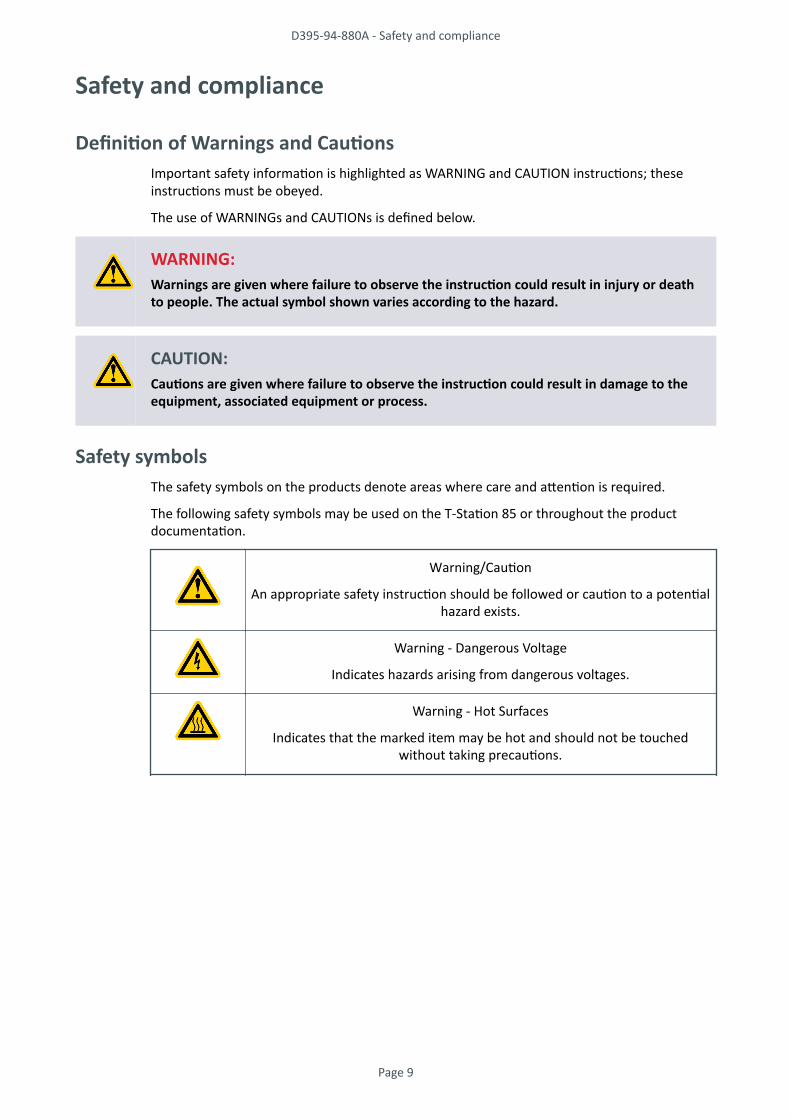
WARNING:Warnings are given where failure to observe the instruction could result in injury or deathto people. The actual symbol shown varies according to the hazard.
CAUTION:Cautions are given where failure to observe the instruction could result in damage to theequipment, associated equipment or process.
Safety symbolsThe safety symbols on the products denote areas where care and attention is required.
The following safety symbols may be used on the T-Station 85 or throughout the productdocumentation.
Warning/Caution
An appropriate safety instruction should be followed or caution to a potentialhazard exists.
Warning - Dangerous Voltage
Indicates hazards arising from dangerous voltages.
Warning - Hot Surfaces
Indicates that the marked item may be hot and should not be touchedwithout taking precautions.
D395-94-880A - Safety and compliance
Page 9
General description
For the general description of the major components used on the T-Station 85, select theappropriate instruction manual reference against each product type.
Diaphragm pump XDD1 A746-02-885
Rotary vane pumps E2M0.7 / E2M1.5 A371-32-880
Turbomolecular pumps nEXT85 B8G0-00-880
OverviewThe T-Station 85 is a small compact fully automatic pumping system which is suitable for awide range of vacuum applications.
The T-Station 85 can be supplied with either an XDD1 oil free diaphragm pump or an E2M1.5rotary vane pump. Both system variants use a nEXT85 turbomolecular pump.
The T-Station 85 is controlled by an easy to use touch pad control module. A single gauge inputincluded can be connected to a range of Edwards active gauges allowing for pressuremeasurement and/or control management of the turbomolecular pump.
The compact size of the T-Station 85 is ideal for use on bench tops or suitable mobileplatforms. The open system configuration allows easy maintenance of the main pumpcomponents.
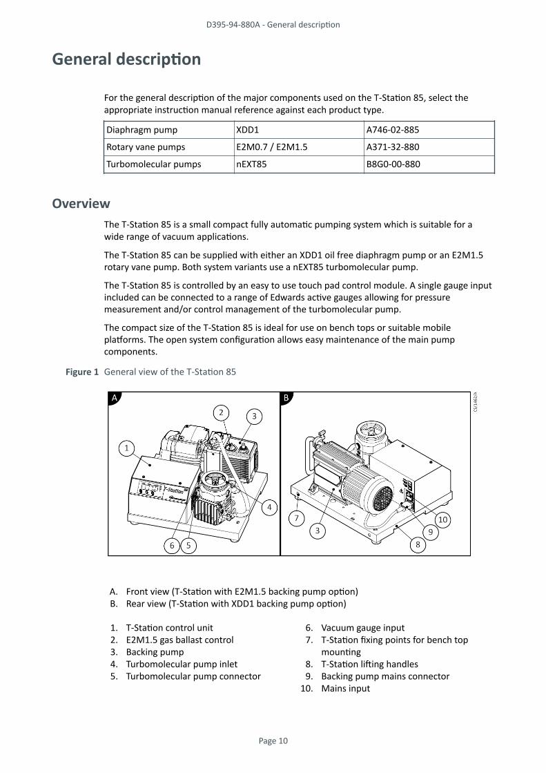
Figure 1 General view of the T-Station 85
A. Front view (T-Station with E2M1.5 backing pump option)B. Rear view (T-Station with XDD1 backing pump option)
1. T-Station control unit2. E2M1.5 gas ballast control3. Backing pump4. Turbomolecular pump inlet5. Turbomolecular pump connector
6. Vacuum gauge input7. T-Station fixing points for bench top
mounting8. T-Station lifting handles9. Backing pump mains connector
10. Mains input
D395-94-880A - General description
Page 10

Installation
Installation safety
WARNING:Risk of injury or damage to equipment. Follow the safety instructions and take note of allappropriate precautions.
• When referring to a manual supplied as a Supplementary Publication, all of theWARNING and CAUTION instructions in the manual must be obeyed.
• A suitably trained and supervised technician must install the T-Station 85.• Check that all the required parts are available and of the correct type before
commencing work.• Ensure that the installation technician is familiar with the safety procedures which
relate to the products pumped.• Wear the appropriate safety clothing when coming into contact with contaminated
components.• Isolate the other components in the system from the electrical supply so that they
cannot be operated accidentally.• Do not reuse O-rings and co-seals if they are damaged.• Dispose of components, grease and oil safely (refer to Disposal on page 32).• Take care to protect sealing faces from damage.• Leak testing the system after installation is complete to ensure optimum vacuum
performance is recommended.
Unpack and inspect1. Remove the outer cover and all packing materials, remove the protective covers from
the inlet and outlet ports, inspect the system for any damage.2. If the T-Station 85 is damaged, notify the supplier and the carrier in writing within
three days; state the item number of the T-Station 85 together with the order numberand the supplier's invoice number. Retain all packing materials for inspection. Do notuse the pump if it is damaged.
3. Check that the package contains the items listed in Table 1 on page 11. If any ofthese items are missing, notify the supplier in writing within three days.
4. If the pump is not to be used immediately, replace the protective covers and store insuitable conditions as described in Storage on page 31.
Table 1 Checklist of items
Quantity Description Check
1 T-Station 85 ❏
1 CD instruction manual P450-00-000 ❏
1 Ultragrade 15 oil 1 litre (supplied with E2M1.5 only) ❏
1 Inlet seal (either trapped O-ring, co-seal or coppercompression gasket suitable for the inlet flange type)
❏
D395-94-880A - Installation
Page 11

Locate the T-Station 85
WARNING:Heavy objects can cause muscle strain or back injury. The mass of the T-Station 85 willdiffer depending on the model supplied.
WARNING:The turbo pump used on the T-Station 85 stores a large amount of kinetic energy when itis running at full speed. In the unlikely event of a malfunction (rotor seizure), the storedenergy could cause a slight movement of the T-Station 85 platform. If the T-Station 85 isoperating on a bench top, taking the following steps is advised: (a) Position the T-Station85 at least 10-15 cm away from the edge of the bench top and adjacent devices and/or (b)Tether or fix the T-Station 85 to the bench top, see Bench top fixing on page 12.
CAUTION:When locating the T-Station 85, care should be taken not to restrict the ventilation gridlocated under the base of the system. Failing to observe this may result in overheating ofthe turbomolecular pump.
Bench top fixingThere are two M8 fixing points located at the rear of the T-Station 85 base (Figure 1 on page10, item 7). Using suitable brackets or straps (not supplied), securing the T-Station 85 to thebench top is recommended to prevent excessive movement in the unlikely event of a pumpfailure.
Note:Straps or brackets cannot be provided as the best type fixing for the customer bench toplocation cannot be determined. Sourcing or fabricating these fixings locally is recommended.
Fill the pump with oilProcedure for filling the pump with the recommended oil.
If the T-Station 85 uses an E2M1.5 rotary vane pump, it must be filled with the correct quantityof oil (supplied) before operating the equipment. For further information refer to the EMRotary Vane Pump manual A371-32-880.
Fill the pump with oil as follows:
1. Remove the oil filler plug.2. Pour oil into the pump until the oil level just reaches the MAX mark on the bezel at the
top of the sight glass. If the oil level goes above the MAX mark, remove the drain plugand drain the excess oil from the pump.
3. After a few minutes, recheck the oil level. If the oil level is now below the MAX mark,pour more oil into the pump.
4. Refit the oil filler plug. Tighten the plug firmly by hand. Do not over tighten.
D395-94-880A - Installation
Page 12

Connect to the vacuum system
WARNING:Connect the turbo pump inlet to the vacuum system before applying power to the T-Station 85. This will ensure that the pump cannot operate accidentally causing injury.
WARNING:If installing the vacuum system directly onto the T-Station 85, the weight of the systemmust be no more than 10 kg and the centre of gravity must be positioned laterally withinthe bounds of the base plate. If this is not the case, the vacuum system must be supportedto ensure that the T-Station 85 does not topple.
1. The turbo pump can be securely fixed to the vacuum system via the inlet flange. Makesure that the pump inlet and all components fitted to the pump inlet are clean anddust-free. If the pump inlet is not kept clean, the pump down time may be increased.
2. If the pump has a CF flange, use the copper compression gasket supplied with thepump and use a full complement of bolts to connect the inlet flange of the pump tothe vacuum system.
3. If the pump has an ISO flange, use a minimum of four claw clamps (each torqued to10 Nm) to connect the inlet flange of the pump to the vacuum system. Alternatively,use a rotatable collar and the combined inlet screen and trapped O-ring supplied withthe pump to connect the inlet flange of the pump to the vacuum system; use a fullcomplement of bolts with the rotatable collar.
4. If the pump has an NW flange, use the centring ring supplied with the pump and ametal NW clamp to connect the inlet flange of the pump to the vacuum system.
5. All inlet flange bolts must be re-tightened once the system is under vacuum. Ensurethat no torques or other forces are transmitted to the pump from the vacuum systemor the associated pipelines.
Connect to the exhaust extraction system
WARNING:Vent dangerous gases and gas mixtures safely. Do not expose people to these gases. Ifpumping hazardous gases or vapours, observe the safety recommendations of the supplierof the gas/vapour.
Note:This section applies to E2M1.5 versions only.
The exhaust system must be configured so that the maximum pressure at the pump outletdoes not exceed 0.5 bar gauge (1.5 bar absolute, 1.5 x 10⁵ Pa) at full pump throughput.
1. Make sure that the exhaust pipeline cannot become blocked.2. If using an exhaust isolation valve, make sure the pump cannot be operated with the
valve closed.
D395-94-880A - Installation
Page 13

Connect the electrical supply
WARNING:Ensure that the electrical installation of the pump conforms with all local and nationalsafety requirements. It must be connected to a suitably fused and protected electricalsupply with a suitable earth point.
CAUTION:Always make the electrical connections to the T-Station 85 after the equipment has beeninstalled on the vacuum system. Always disconnect the electrical supply from the T-Station85 before removing the equipment from the vacuum system.
Check that the electrical supply is suitable for this equipment. Refer to Table 22 on page 42for the electrical requirements for this equipment.Make the electrical connection to the T-Station 85 using a cable fitted with an IEC60320connector.A range of suitable cables is available from the supplier.
Configure the T-Station 85As supplied from the factory, the T-Station 85 will control the system as follows:
System start is selected:
• The TAV vent valve will close.• The backing pump will turn on.• The turbomolecular pump will start accelerating up to full rotational speed.
System off is selected:
• The backing pump will turn off.• The turbomolecular pump drive will turn off and the pump will start to decelerate.• The TAV vent valve will open fully from 50% of full rotational speed.
Turbo pump delayThe T-Station 85 can be configured to delay the turbo pump after the backing pump hasstarted.
Refer to Turbo setpoint screen on page 22. The delay is helpful to prevent the turbomolecularpump from accelerating under high pressure for a prolonged period if the volume beingpumped is greater than 2 litres. This option is especially useful if the T-Station 85 uses an XDD1diaphragm pump.
Figure 2 on page 15 shows the recommended delay period for a turbo / XDD1 pumpcombination.
* This operation refers to systems which have been fitted with an Edwards TAV vent valve (optionalaccessory). For more vent options refer to Vent valve screen on page 20.
D395-94-880A - Installation
Page 14

Figure 2 Turbomolecular pump start delay with XDD1 diaphragm pump
Connect a vacuum gaugeA single compatible active gauge can be fitted to the T-Station 85.Fit the gauge using an Edwards active gauge cable into the gauge connector located on the sideof the controller housing (refer to Figure 1 on page 10, item 6). For active gauge control and setup refer to Gauge screen on page 19.The following Edwards active gauges are suitable for use with the T-Station 85:
• APG100 Active Pirani vacuum gauge• APGX-H Active Linear Convection gauge• AIM-X Active Inverted Magnetron gauge• ASG Active Strain gauge
Commission the installationAfter installing the T-Station 85, the system must be tested.
Use the following procedure to test the system:
1. Make sure that all the electrical connections are secure.2. Switch on the electrical supply and the exhaust extraction system (if available).3. To operate the system press the START/STOP key. Check that the equipment operates
as described in .4. Check that the turbo pump reaches normal speed. If the pump inlet is valved or
capped off, it should take approximately 100 - 150 seconds for the turbo to reachnormal speed. If a vacuum chamber is attached to the pump inlet, this time may takelonger.
5. To turn OFF the system, press the START/STOP key followed by the ENTER key toconfirm. Check that the equipment closes down as described in .
For full operational details and how to navigate using the front panel control key pad refer to Menu structure on page 17.
D395-94-880A - Installation
Page 15

Operation
WARNING:Do not attempt to move the T-Station 85 while the turbo pump is rotating. Doing so maycause severe damage to the pump and could cause injury.
CAUTION:To familiarise yourself with the vacuum pumps installed on the T-Station 85, it is advisableto read the relevant instruction manuals (refer to General description on page 10).
Control panel descriptionFigure 3 Front panel display
1. Start/ Stop2. Enter
3. Next
Table 2 Front panel symbols and their functionsl
Key pad symbol Name Function
1 START/STOP Turns the pumps on and off.
Returns to turbo menu screen.
2 ENTER Selects or confirms current menu option.
Controls active gauges.
3 NEXT Moves to next menu.
Scrolls through menu options.
The LEDs along the top of the T-Station 85 display indicate which menu screen is currentlybeing shown on the numeric display. To move to the next menu item press the NEXT key and toreturn to the turbo menu screen press the START/STOP key. The available items are listed inorder in Table 3 on page 17.
D395-94-880A - Operation
Page 16
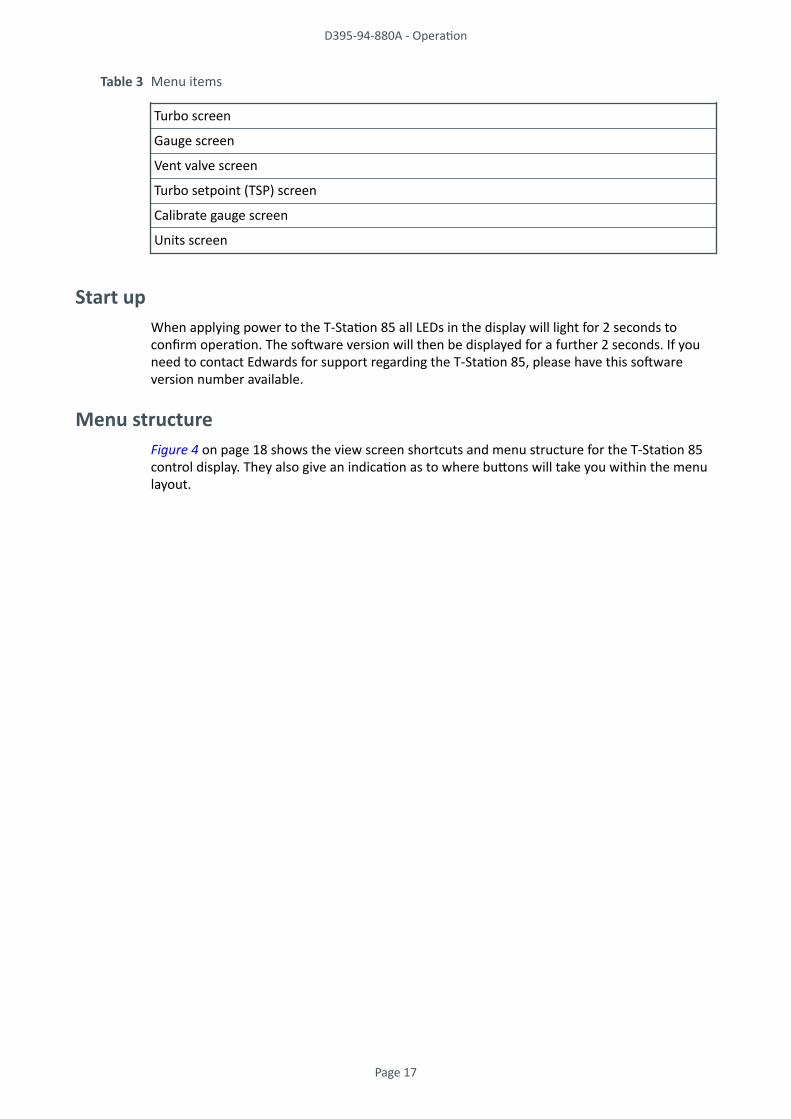
Table 3 Menu items
Turbo screen
Gauge screen
Vent valve screen
Turbo setpoint (TSP) screen
Calibrate gauge screen
Units screen
Start upWhen applying power to the T-Station 85 all LEDs in the display will light for 2 seconds toconfirm operation. The software version will then be displayed for a further 2 seconds. If youneed to contact Edwards for support regarding the T-Station 85, please have this softwareversion number available.
Menu structureFigure 4 on page 18 shows the view screen shortcuts and menu structure for the T-Station 85control display. They also give an indication as to where buttons will take you within the menulayout.
D395-94-880A - Operation
Page 17
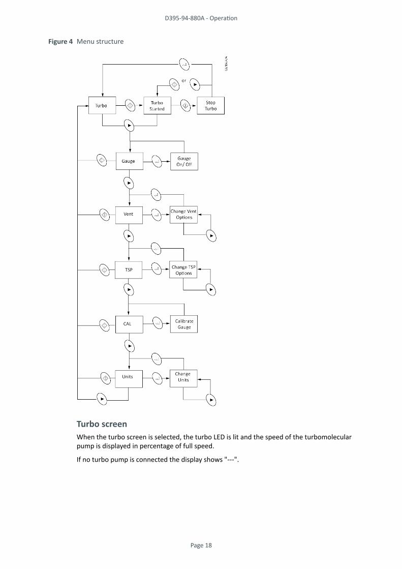
Figure 4 Menu structure
Turbo screenWhen the turbo screen is selected, the turbo LED is lit and the speed of the turbomolecularpump is displayed in percentage of full speed.
If no turbo pump is connected the display shows "---".
D395-94-880A - Operation
Page 18
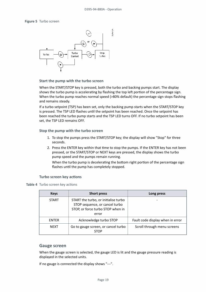
Figure 5 Turbo screen
Start the pump with the turbo screenWhen the START/STOP key is pressed, both the turbo and backing pumps start. The displayshows the turbo pump is accelerating by flashing the top left portion of the percentage sign.When the turbo pump reaches normal speed (>80% default) the percentage sign stops flashingand remains steady.If a turbo setpoint (TSP) has been set, only the backing pump starts when the START/STOP keyis pressed. The TSP LED flashes until the setpoint has been reached. Once the setpoint hasbeen reached the turbo pump starts and the TSP LED turns OFF. If no turbo setpoint has beenset, the TSP LED remains OFF.
Stop the pump with the turbo screen
1. To stop the pumps press the START/STOP key; the display will show "Stop" for threeseconds.
2. Press the ENTER key within that time to stop the pumps. If the ENTER key has not beenpressed, or the START/STOP or NEXT keys are pressed, the display shows the turbopump speed and the pumps remain running.When the turbo pump is decelerating the bottom right portion of the percentage signflashes until the pump has completely stopped.
Turbo screen key actions
Table 4 Turbo screen key actions
Keys Short press Long press
START START the turbo, or initialise turboSTOP sequence, or cancel turbo
STOP, or force turbo STOP when inerror
-
ENTER Acknowledge turbo STOP Fault code display when in error
NEXT Go to gauge screen, or cancel turboSTOP
Scroll through menu screens
Gauge screenWhen the gauge screen is selected, the gauge LED is lit and the gauge pressure reading isdisplayed in the selected units.
If no gauge is connected the display shows "---".
D395-94-880A - Operation
Page 19

Connect a gaugeWhen a gauge is first connected the display shows "ID" followed by a number to identify thenew gauge.
If the gauge is an Active Strain Gauge (ASG), the display then goes to ASG range select,otherwise the display reverts to showing the pressure reading. If the gauge type is notsupported the display shows "???". When no gauge is connected the display shows "---".
Figure 6 Gauge screen
ASG range selectWhen an ASG is connected the display changes to select the ASG range. 1000 mbar is assumedby default, and the display flashes "1.03".Press the NEXT key to select between 1000 and 2000 mbar, then press the ENTER key toconfirmed the selection.
Gauge ON/OFF controlGauges which support ON/OFF control (e.g. AIM gauges) can be turned ON and OFF using theENTER key.
When first connected the gauge is in the OFF state and the display shows "OFF". When thegauge is turned on the display will show "Str" whilst the gauge is starting up, and will thendisplay pressure.
Gauge screen key actions
Table 5 Gauge screen key actions
Keys Short press Long press
START Go to turbo screen -
ENTER ON/OFF control of supported gaugeor acknowledge error
-
NEXT Go to vent control screen Scroll through menu screens
Vent valve screenIf a TAV solenoid vent valve is connected to the turbo pump podule the operation of the valveis controlled by the vent valve screen.
When the vent valve screen is selected, the vent LED is lit and the current vent valve controlsetting is displayed. The default is "50%". The vent valve screen is not available if the turbopump is running.
1. Select the appropriate setting for either normally open or normally closed vent valve.
D395-94-880A - Operation
Page 20

2. To change the vent valve setting press the ENTER key, then use the NEXT key to choosebetween 50%, Ctrld and FAN.
3. Press the ENTER key again to confirm the selection.
Table 6 Vent valve screen
50
no
Normally open vent valves. Vent valve opens fully when the speed of the turbo pumpdrops below 50% full rotational speed.
Ctl
no
Normally open vent valves. Controlled venting from 100% to 50% full rotationalspeed; vent valve opens fully below 50%.
Fan Normally open vent valves. The vent valve connection on the turbo pump ispermanently powered so that the vent valve will remain closed. This can also be usedto provide power to an air cooler (for example, ACX75).
Off Normally closed vent valves. The vent valve connection on the turbo pump ispermanently disabled so the vent valve will remain closed.
50
nc
Normally closed vent valves. The vent valve will open when the speed of the turbopump has dropped below 50% during stop but not fail conditions.
Ctl
nc
Normally closed vent valves. Controlled venting from 100% to 50% full rotationalspeed, vent valve opens fully below 50% during stop but not fail conditions.
Figure 7 Vent valve screen
Vent valve screen key actions
Table 7 Vent valve screen key actions
Keys Short press Long press
START Go to turbo screen -
ENTER Enter edit mode, or confirmselection
-
NEXT Next vent option, or go to TSPcontrol screen
Scroll through vent options in editmode or scroll through menu
screens
D395-94-880A - Operation
Page 21

Turbo setpoint screenThe turbo setpoint screen is used to configure the start delay of the turbo pump.
When the turbo setpoint screen is selected, the TSP LED is lit and the current setpoint isdisplayed. The default is "OFF". The turbo setpoint menu is not available if the turbo pump isrunning or the selected units are volts.
1. To change the turbo setpoint press the ENTER key, then use the NEXT key to choosebetween off, time delay and pressure setpoint.
2. Press the ENTER key again to confirm the selection.3. When time delay is selected the display will show the delay time in seconds. The
default time is 120 s. This means that the turbo pump will start after a delay of 120 sfrom when the START key is pressed. To change the value of the delay time press andhold the ENTER key to start number entry mode.
4. If an active gauge is connected to the system the pressure setpoint can be used to startthe turbo pump once the pressure has fallen below the setpoint value. When pressureis selected the display shows the setpoint pressure. The default pressure is "5.00" mbarshown as an exponential. To change the pressure setpoint, press and hold the ENTERkey to start number entry mode.
Note:If the turbo setpoint is set to pressure but a gauge is not connected the turbo pump will notstart.
Figure 8 Turbo setpoint screen
Number entry modeWhen the ENTER key is pressed and held on either the time or pressure option, number entrymode is entered. The first digit starts flashing and the time or pressure can be edited.
1. Press the NEXT key to adjust the value, then press the ENTER key to confirm the digitand then move on to the second digit, which is adjusted similarly. The ENTER keyconfirms the digit and then moves to the final digit of the time setpoint or theexponent of the pressure setpoint. The exponent of the pressure setpoint is adjustedas a single value in the range - 10 to + 6.
2. The final press of ENTER confirms the complete number and returns to showing thesetpoint value. The TSP is set after the complete number is entered.
D395-94-880A - Operation
Page 22

Figure 9 Turbo setpoint number entry mode
Turbo setpoint screen key actions
Table 8 Turbo setpoint screen key actions
Keys Short press Long press
START Go to turbo screen -
ENTER Enter edit mode, or confirmselection
Enter number entry mode
NEXT Next TSP option, next number or goto gauge calibration screen
Scroll through TSP options in editmode, scroll through numbers innumber entry or scroll through
menu screens
Calibrate gauge screenWhen the calibrate gauge screen is selected, the gauge LED and the CAL LED are lit together.The numeric display is blank. The calibrate gauge menu is not available for gauges which do notsupport calibration.
When the ENTER key is pressed the action depends on gauge type:
WRG or APGX: The calibration command is sent to the gauge and the display shows "CALd" for3 seconds.
ASG: The calibration functions as a zero offset adjustment. The pressure currently displayed issaved as the zero offset and is subtracted from all future readings. The display shows "CALd"for 3 seconds to confirm the action. The offset adjustment can be cancelled by pressing theENTER key again. The display shows "OFF" for 3 seconds to confirm that the offset adjustmenthas been removed.
D395-94-880A - Operation
Page 23

Figure 10 Calibrate gauge screen
Calibrate gauge screen key actions
Table 9 Calibrate gauge screen key actions
Keys Short press Long press
START Go to turbo screen -
ENTER Calibrate gauge -
NEXT Go to units screen Scroll through menu screens
Units screenWhen the units screen is selected, the menu LEDs are unlit and the currently selected units LEDis lit. The numeric display is blank.To change the units press the ENTER key and use the NEXT key to choose between mbar, Torr,Pa and voltage. Press the ENTER key again to confirm the selection. Note that when voltage isselected the display shows " 0.000".When the units are changed, the setpoint values will be converted to the new units. Forexample, if a setpoint threshold is entered as 1.0 x 10⁻³ mbar and the units are changed toTorr, then the value will be displayed as 7.5 x 10⁻⁴ Torr.
Figure 11 Units screen
Units screen key actions
Table 10 Units screen key actions
Keys Short press Long press
START Go to turbo screen -
ENTER Enter edit mode, or confirmselection
-
NEXT Next units option, or go to turboscreen
Scroll through units in edit mode, orscroll through menu screens
D395-94-880A - Operation
Page 24

Gas ballast control (E2M1.5)Use the gas ballast control to change the amount of air (or inert gas) introduced into the lowvacuum stage of the pump.
Use of the gas ballast will prevent the condensation of vapours in the pump; the condensateswould contaminate the oil.
Use the gas ballast control (Figure 1 on page 10, item 2) closed:
• to achieve ultimate vacuum• to pump dry gases.
Turn the gas ballast control six turns anti-clockwise to open it fully.
Use the gas ballast control open:
• to pump high concentrations of condensable vapour• to pump high concentrations of condensable vapour
When operating the pump with the gas ballast control open, there will be an increased rate ofoil loss from the pump.
Electrical supply failure
WARNING:Risk of injury or death. If the power supply fails when the pump is running, the impellercould continue to spin for approximately 10 minutes. The control circuit may not give anyindication that the impeller is still running.
If the electrical supply to the T-Station 85 fails when the turbo pump is rotating, the motor ofthe turbo pump is used as a generator. The regenerated power is used to maintain the controlsystem and the display. The regenerated power is not used to maintain the T-Station 85 controlsystem or the display.
When power to the control system is lost, no indication will be given about pump rotationalspeed, yet the impeller may still be turning.
The system will not restart when the power is reinstated.
D395-94-880A - Operation
Page 25
Maintenance
Maintenance safety
WARNING:Risk of injury or damage to equipment. Follow the safety instructions and take note of allappropriate precautions.
• When referring to a manual supplied as a Supplementary Publication, all of theWARNING and CAUTION instructions in the manual must be obeyed.
• A suitably trained and supervised technician must maintain the T-Station 85.• Allow the system to cool (so that it is at a safe temperature for skin contact) before
starting maintenance work. Make sure the system is switched off in case the thermaloverload device restarts the system.
• Check that all the required parts are available and of the correct type before startingwork.
• Ensure that the maintenance technician is familiar with the safety procedures whichrelate to the pump oil and the products processed by the pumping system.
• Isolate the system and other components from the electrical supply so that theycannot be operated accidentally.
• Do not reuse O-rings and seals if they are damaged.• Dispose of components, grease and oil safely (refer to Disposal on page 32).• Protect sealing faces from damage.• Leak testing the system is recommended after maintenance. Seal any leaks found if any
vacuum or exhaust pipeline connections have been disconnected.
Maintenance plan
WARNING:If the turbo pump is removed from the T-Station 85 platform, it is important to retain andreuse the same fixing screws. If any of these screws are lost or cannot be used, thefollowing type M5 x 12 mm CAP HD high tensile class 12.9 must be used. If this warning isignored and the turbo pump seizes, the stored energy in the turbo pump may cause someor all of the screws to fail. This may result in the turbo pump being ejected from the T-Station 85 base.
List of instruction manuals that state the minimum maintenance operations necessary tomaintain the T-Station 85 in normal use:
Diaphragm pump XDD1 A746-02-885
Rotary vane pumps E2M0.7 / E2M1.5 A371-32-880
Turbomolecular pumps nEXT85 B8G0-00-880
More frequent maintenance may be necessary if the T-Station 85 has been used to pumpcorrosive or abrasive gases and vapour. If necessary, adjust the maintenance plan according toyour experience.
D395-94-880A - Maintenance
Page 26

Inspect the hoses, pipelines and connections1. Inspect all of the electrical connections and check that they are secure. Tighten any
loose connections.2. Inspect all of the electrical cables and check that they are not damaged and have not
overheated. Replace or repair any damaged or overheated cable.3. Inspect all of the vacuum and exhaust connections and check that they are secure.
Tighten any loose connections.4. Inspect all of the vacuum and exhaust pipelines and check that they are not corroded
or damaged and that they do not leak. Replace or repair any corroded or damagedcomponent and seal any leaks found.
Factory default settingsProcedure to return the T-Station 85 to the factory default settings.
1. Remove the mains power from the T-Station 85.2. Press the NEXT key and hold it down whilst reapplying mains power. Continue holding
down the NEXT key until "Err01" is displayed.3. Remove and reapply mains power. The factory defaults will now be set.
D395-94-880A - Maintenance
Page 27

Fault finding
The T-Station 85 has failed to start
Cause The electrical supply fuse has blown.
Remedy Replace the fuse. Refer to Table 19 on page 40.Cause The operating voltage is incorrect.
Remedy Check the voltage supply matches the T-Station 85 voltage requirements. Refer to theelectrical rating label located at the rear of the T-Station 85.
Ultimate pressure cannot be reached
Cause Pressure is limited by water vapour.
Remedy Bake the chamber or run the system for a duration until the vacuum improves.Cause The vacuum gauges are contaminated.
Remedy Clean or replace the vacuum gauges.Cause Pumping speed is insufficient due to poor conductance between the pump and the gauge or
the chamber is too large.
Remedy Increase the conductance or reduce the volume.Cause The backing pressure is > 10 mbar (1x10³ Pa).
Remedy The backing pressure may be too high. Check for backing pipeline leaks. If the throughput ishigh, a larger backing pump may be required.
Cause The high vacuum area of the system is contaminated.
Remedy Clean the high vacuum system.Cause Check the rest of the system for leaks and contamination.
Remedy If found, repair the leaks and clean the contamination.Cause The inlet pressure is poor.
Remedy If inlet pressure is poor, check the turbo pump for contamination and refer to theTroubleshooting section of the turbo pump manual.
Leak test the pump. If the leak rate > 1x10⁻⁷ mbar l s-1 (1x10⁻⁵ Pa l s-1), contact the supplier orEdwards.
The backing pump is noisy
Cause Listed in Fault Finding section of the backing pump manual.Remedy Refer to the Fault Finding section of the backing pump manual. See General description on
page 10.
The backing pump is leaking oil
Cause Listed in Fault Finding section of the backing pump manual.Remedy Refer to the Fault Finding section of the backing pump manual. See General description on
page 10.
D395-94-880A - Fault finding
Page 28

The turbo pump is very noisy or there is excessive vibration or both
Cause Listed in Troubleshooting section of the turbo pump manual.Remedy Refer to the Troubleshooting section of the turbo pump manual. See General description on
page 10.
Error numbersIf an error is detected by the controller the display will show "Err" followed by a number.
Refer to Table 11 on page 29 for a description of the error together with likely causes andsuggested remedies.
Table 11 Error numbers
ErrorNumber
Meaning Possible cause/remedy
Controller errors
1 EEPROM error The internal EEPROM checksum has failed. All usersettings will revert to the factory default.
2 ID reference error The reference used for identifying gauges isincorrect. Please remove all connected gauges, turnthe electrical supply off and on, and wait for 30seconds before reconnecting the gauges.
Gauge errors
11 Gauge voltage too high The voltage from a gauge is too high. The gauge maybe defective.
12 Gauge voltage too low The voltage from a gauge is too low. The gauge maybe defective.
21 WRG Pirani failure Errors specific to WRG. Refer to the WRG manual fordetails. Press the ENTER key to clear the error fromthe display once the fault has been corrected.
22 WRG magnetron short
23 WRG striker fail
24 WRG magnetron notstruck
25 APGX filament failure Errors specific to APGX. Refer to the APGX manual fordetails. Press the ENTER key to clear the error fromthe display once the fault has been corrected.
26 APGX cal err
27 APGXH tube not fitted
D395-94-880A - Fault finding
Page 29

ErrorNumber
Meaning Possible cause/remedy
Pump errors
41 Turbo pump fault Inspect the LEDs on the turbo pump podule forstatus information. For more detailed fault codes,press and hold the ENTER key (whilst Err41 isshowing) to display the turbo pump system statusword. The lower 16 bits of the status word aredisplayed in hexadecimal. Press the START / STOP keyto clear the error message. Refer to the instructionmanual of the turbo pump for detailed fault finding.
D395-94-880A - Fault finding
Page 30

Storage
Use the following procedure to store the T-Station 85.
1. Shut down the T-Station 85 as described in Stop the pump with the turbo screen onpage 19.
2. Isolate the T-Station 85 from the electrical supply and disconnect it from the vacuumsystem.
3. Drain the oil from the backing pump (only applicable to the E2M1.5 rotary vane pump)as described in the instruction manual, (refer to General description on page 10).
4. Place protective covers over the inlet and outlet flanges.5. For the fastest pump down after the T-Station 85 is reinstalled, seal the
turbomolecular pump inside a plastic bag together with a suitable desiccant.6. Store the T-Station 85 in cool, dry conditions until required for use.
D395-94-880A - Storage
Page 31
Disposal
Dispose of the T-Station 85 and any components and accessories safely and in accordance withall local and national safety and environmental requirements.
Particular care must be taken with any components that have been contaminated withdangerous process substances.
For instruction on draining the oil from the E2M1.5 rotary vane pump refer to the instructionmanual for the pump. Refer to General description on page 10.
D395-94-880A - Disposal
Page 32
Service
Note:Edwards policy is to provide support for product after obsolescence through various optionsincluding maintenance, repair, enhancement and replacement. Support will be available forseveral years after product obsolescence and in compliance with any applicable legislation.Edwards will always undertake appropriate actions to ensure support is maintained and,where support is no longer possible, will ensure this is communicated to all affectedcustomers with a suitable notice period.
Edwards products, spares and accessories are available from Edwards companies in Belgium,Brazil, China, France, Germany, Israel, Italy, Japan, Korea, Singapore, United Kingdom, U.S.A anda world-wide network of distributors. The majority of these centres employ Service Engineerswho have undergone comprehensive Edwards training courses.
Order spare parts and accessories from the nearest Edwards company or distributor. Whenordering, state for each part required:
• Model and Item Number of the equipment• Serial number• Item Number and description of part.
Edwards products are supported by a world-wide network of Edwards Service Centres. EachService Centre offers a wide range of options including: equipment decontamination; serviceexchange; repair; rebuild and testing to factory specifications. Equipment which has beenserviced, repaired or rebuilt is returned with a full warranty.
Local Service Centres can also provide Edwards engineers to support on-site maintenance,service or repair of equipment. For more information about service options, contact thenearest Service Centre or other Edwards company.
D395-94-880A - Service
Page 33

Spares
CAUTION:Use of non-Edwards spares may result in reduced reliability and performance and willinvalidate product warranty.
The spares available for the turbo pump and backing pumps are listed in the CD instructionmanuals supplied with your equipment. Refer to General description on page 10.
D395-94-880A - Spares
Page 34
Accessories
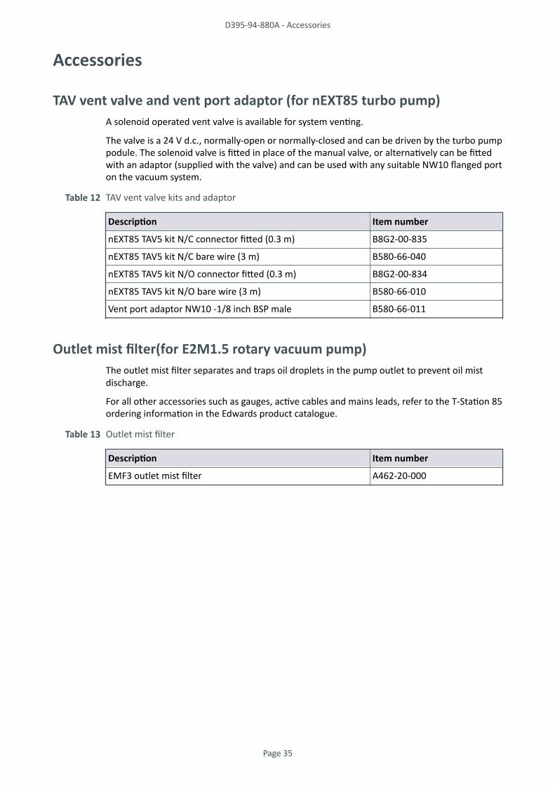
TAV vent valve and vent port adaptor (for nEXT85 turbo pump)A solenoid operated vent valve is available for system venting.
The valve is a 24 V d.c., normally-open or normally-closed and can be driven by the turbo pumppodule. The solenoid valve is fitted in place of the manual valve, or alternatively can be fittedwith an adaptor (supplied with the valve) and can be used with any suitable NW10 flanged porton the vacuum system.
Table 12 TAV vent valve kits and adaptor
Description Item number
nEXT85 TAV5 kit N/C connector fitted (0.3 m) B8G2-00-835
nEXT85 TAV5 kit N/C bare wire (3 m) B580-66-040
nEXT85 TAV5 kit N/O connector fitted (0.3 m) B8G2-00-834
nEXT85 TAV5 kit N/O bare wire (3 m) B580-66-010
Vent port adaptor NW10 -1/8 inch BSP male B580-66-011
Outlet mist filter(for E2M1.5 rotary vacuum pump)The outlet mist filter separates and traps oil droplets in the pump outlet to prevent oil mistdischarge.
For all other accessories such as gauges, active cables and mains leads, refer to the T-Station 85ordering information in the Edwards product catalogue.
Table 13 Outlet mist filter
Description Item number
EMF3 outlet mist filter A462-20-000
D395-94-880A - Accessories
Page 35

Technical Reference
Note:The operating, storage conditions and performance of the T-Station 85 may depend on thetype of backing pump fitted to the T-Station 85; refer to the technical data in the appropriatesupplementary publications as listed in General description on page 10.
Operating and storage conditionsTable 14 Operating and storage conditions
Parameter Value Units
Ambient operating temperature range 12 to +40 °C
Ambient storage temperature range -30 to +70 °C
Maximum operating humidity maximum 90condensing at 40
% RH and °C
Maximum operating altitude 2000 maximum m
Sound level 56 dB(A)
Pollution degree (EN61010) 2 -
Maximum outlet pressure
- XDD1 pump
- E2M1.5 pump
1.1 (1.1 x 10⁵)
1.5 (1.5 x 10⁵)
bar absolute (Pa)
Maximum permitted external magnetic field(nEXT85 turbo)
5 mT
Mechanical dataTable 15 Mechanical data
Parameter Data
Dimensions Refer to Figure 12 on page 37
Degree of protection (to IEC34-5:1981) IP20
Mass:
- XDD1 combination
- E2M1.5 combination
17 kg max
21 kg max
D395-94-880A - Technical Reference
Page 36

Figure 12 Dimensions - T-Station 85
All measurements indicated are shown in mm (inches)
Pump performance dataTable 16 Pump performance data - nEXT85H
Turbomolecular pump type nEXT85H ISO63 nEXT85H CF63 nEXT85H NW40
Inlet pumping speed:
Nitrogen 84 ls-1 84 ls-1 47 ls-1
Helium 78 ls-1 78 ls-1 61 ls-1
Hydrogen 54 ls-1 54 ls-1 49 ls-1
Argon 80 ls-1 80 ls-1 44 ls-1
Inlet compression ratio:
Nitrogen > 1 E+11 > 1 E+11 > 1 E+11
Helium 2 E+07 2 E+07 2 E+07
Hydrogen 5 E+05 5 E+05 5 E+05
Argon > 1 E+11 > 1 E+11 > 1 E+11
Ultimate pressure:
with rotary vane backing pump * < 5 E-09 mbar < 5 E-10 mbar < 5 E-09 mbar
with diaphragm backing pump § < 5 E-08 mbar < 5 E-09 mbar < 5 E-08 mbar
* Ultimate pressure 48 hours after bakeout with 2-stage rotary vane backing pump.§ Ultimate pressure 48 hours after bakeout with backing pressure < 5 mbar (500 Pa).
D395-94-880A - Technical Reference
Page 37

Table 17 Pump performance data - nEXT85D
Turbomolecular pump type nEXT85D ISO63 nEXT85D CF63 nEXT85D NW40
Inlet pumping speed:
Nitrogen 84 ls-1 84 ls-1 47 ls-1
Helium 78 ls-1 78 ls-1 61 ls-1
Hydrogen 60 ls-1 60 ls-1 49 ls-1
Argon 80 ls-1 80 ls-1 44 ls-1
Inlet compression ratio:
Nitrogen > 1 E+11 > 1 E+11 > 1 E+11
Helium 8 E+06 8 E+06 8 E+06
Hydrogen 2 E+05 2 E+05 2 E+05
Argon > 1 E+11 > 1 E+11 > 1 E+11
Ultimate pressure:
with rotary vane backing pump * < 5 E-09 mbar < 5 E-10 mbar < 5 E-09 mbar
with diaphragm pump § < 5 E-08 mbar < 5 E-09 mbar < 5 E-08 mbar
* Ultimate pressure 48 hours after bakeout with 2-stage rotary vane backing pump.§ Ultimate pressure 48 hours after bakeout with backing pressure < 5 mbar (500 Pa).
Pumped media
WARNING:Vent dangerous gases and gas mixtures safely. Do not expose people to these gases. Ifpumping hazardous gases or vapours, observe the safety recommendations of the supplierof the gas/vapour.
WARNING:Do not use the pump to pump pyrophoric or explosive gas mixtures as it is not suitable forthis purpose. The pump and its connections are not designed to contain an explosion.
WARNING:Do not expose any part of the human body to the vacuum as this could result in injury toor death of people.
CAUTION:Do not use the pump to pump particulates or condensable media. Deposition may occurwithin the pump which will degrade pump performance and reduce the pump life.
D395-94-880A - Technical Reference
Page 38
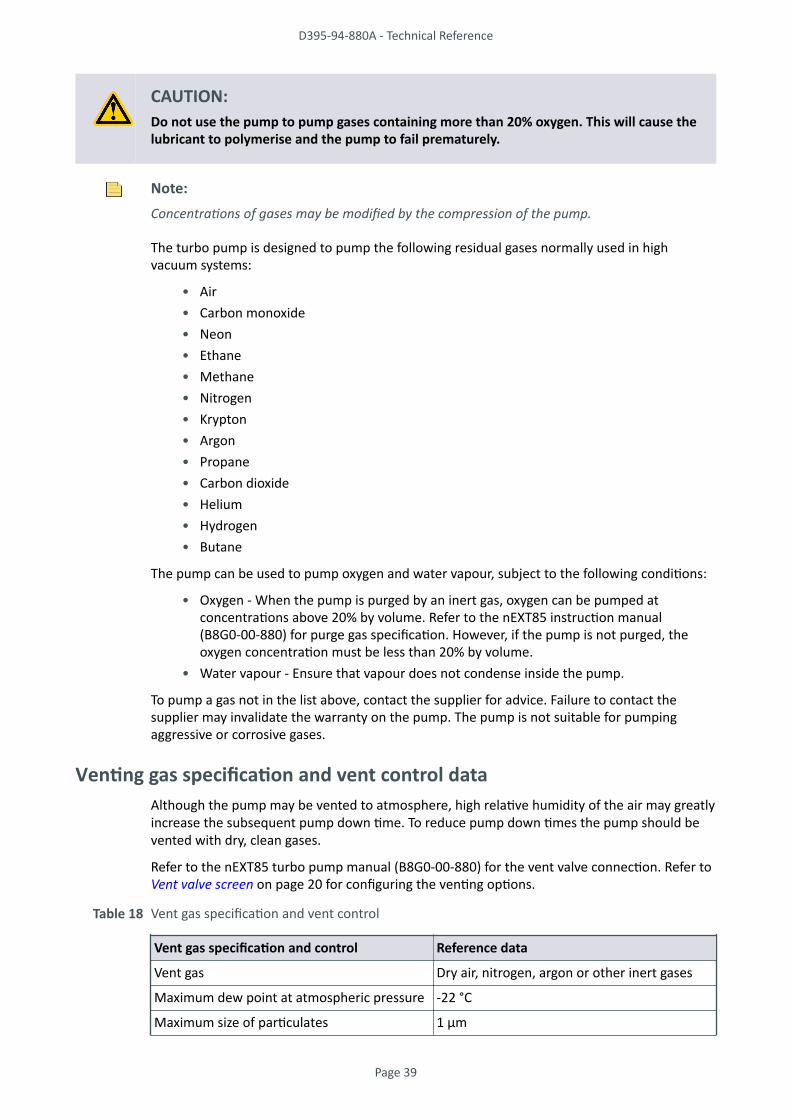
CAUTION:Do not use the pump to pump gases containing more than 20% oxygen. This will cause thelubricant to polymerise and the pump to fail prematurely.
Note:Concentrations of gases may be modified by the compression of the pump.
The turbo pump is designed to pump the following residual gases normally used in highvacuum systems:
• Air• Carbon monoxide• Neon• Ethane• Methane• Nitrogen• Krypton• Argon• Propane• Carbon dioxide• Helium• Hydrogen• Butane
The pump can be used to pump oxygen and water vapour, subject to the following conditions:
• Oxygen - When the pump is purged by an inert gas, oxygen can be pumped atconcentrations above 20% by volume. Refer to the nEXT85 instruction manual(B8G0-00-880) for purge gas specification. However, if the pump is not purged, theoxygen concentration must be less than 20% by volume.
• Water vapour - Ensure that vapour does not condense inside the pump.
To pump a gas not in the list above, contact the supplier for advice. Failure to contact thesupplier may invalidate the warranty on the pump. The pump is not suitable for pumpingaggressive or corrosive gases.
Venting gas specification and vent control dataAlthough the pump may be vented to atmosphere, high relative humidity of the air may greatlyincrease the subsequent pump down time. To reduce pump down times the pump should bevented with dry, clean gases.
Refer to the nEXT85 turbo pump manual (B8G0-00-880) for the vent valve connection. Refer to Vent valve screen on page 20 for configuring the venting options.
Table 18 Vent gas specification and vent control
Vent gas specification and control Reference data
Vent gas Dry air, nitrogen, argon or other inert gases
Maximum dew point at atmospheric pressure -22 °C
Maximum size of particulates 1 μm
D395-94-880A - Technical Reference
Page 39
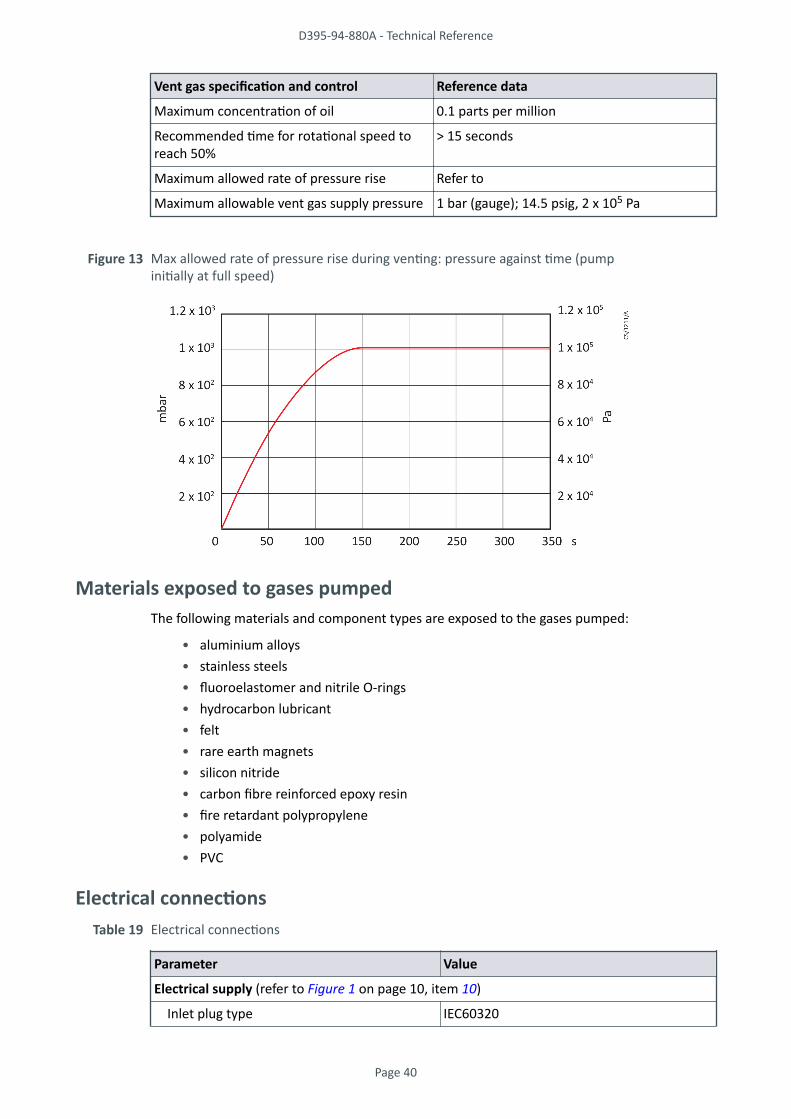
Vent gas specification and control Reference data
Maximum concentration of oil 0.1 parts per million
Recommended time for rotational speed toreach 50%
> 15 seconds
Maximum allowed rate of pressure rise Refer to
Maximum allowable vent gas supply pressure 1 bar (gauge); 14.5 psig, 2 x 10⁵ Pa
Figure 13 Max allowed rate of pressure rise during venting: pressure against time (pumpinitially at full speed)
Materials exposed to gases pumpedThe following materials and component types are exposed to the gases pumped:
• aluminium alloys• stainless steels• fluoroelastomer and nitrile O-rings• hydrocarbon lubricant• felt• rare earth magnets• silicon nitride• carbon fibre reinforced epoxy resin• fire retardant polypropylene• polyamide• PVC
Electrical connectionsTable 19 Electrical connections
Parameter Value
Electrical supply (refer to Figure 1 on page 10, item 10)
Inlet plug type IEC60320
D395-94-880A - Technical Reference
Page 40

Parameter Value
Integral fuse rating 10 A Type T, 20 mm
Backing pump (refer to Figure 1 on page 10, item 9)
Outlet socket type IEC60320
Turbomolecular pump (refer to Figure 1 on page 10, item 5)
Connector type 15-way sub-miniature 'D' type socket
Power supply 24 V d.c. nominal
Maximum power rating 4 W
Active gauge (refer to Figure 1 on page 10, item 6)
Connector type RJ45 8-way
Power supply 24 V d.c. nominal
Maximum power rating 4 W
Figure 14 Pin connections for 15-way sub-miniature 'D' type socket
Table 20 Turbo pump connector pin-out
Pin Function
1 Power supply positive
2 Signal common
3 Start signal output
4 RS232 Tx
5 Serial enable output
6 Power supply positive
7 RS232 Rx
8 Power supply common
9 Speed signal input
10 Screen
11 Power supply positive
12 Screen
13 Power supply common
14 Power supply common
15 Normal signal input
D395-94-880A - Technical Reference
Page 41

Figure 15 Pin connections for an 8-way RJ45
Table 21 Active gauge connector pin-out
Pin Function
1 Power supply positive
2 Power supply common
3 Signal input
4 Identification
5 Signal common
6 Control line 1
7 Control line 2
8 Not connected
Electrical dataIf the T-Station 85 uses an E2M1.5, the motor start up current is drawn for less than onesecond, so slow-blow fuses must be used to prevent unnecessary fuse failure when the pumpstarts. If using the pump at temperatures lower than 12 °C (53.6 °F), the start up current will bedrawn for longer; this may cause the motor thermal overload device to open.
Table 22 Electrical data
Supply Voltage
50/60 Hz
Current (A) Power (W)
Full load Start
XDD1 / nEXT85
100 3.1 - 310
120 2.6 - 310
200 1.6 - 310
230 1.35 - 310
E2M1.5 / nEXT85
100 4.7 13.6 470
120 3.92 12.0 470
200 2.2 6.4 430
230 1.9 5.7 430
D395-94-880A - Technical Reference
Page 42
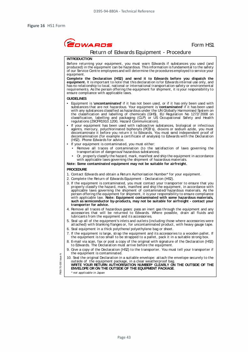
Figure 16 HS1 Form
Return of Edwards Equipment - ProcedureForm HS1
INTRODUCTIONBefore returning your equipment, you must warn Edwards if substances you used (andproduced) in the equipment can be hazardous. This information is fundamental to the safetyof our Service Centre employees and will determine the procedures employed to service yourequipment.Complete the Declaration (HS2) and send it to Edwards before you dispatch theequipment. It is important to note that this declaration is for Edwards internal use only, andhas no relationship to local, national or international transportation safety or environmentalrequirements. As the person offering the equipment for shipment, it is your responsibility toensure compliance with applicable laws.
GUIDELINES• Equipment is 'uncontaminated' if it has not been used, or if it has only been used with
substances that are not hazardous. Your equipment is 'contaminated' if it has been usedwith any substances classified as hazardous under the UN Globally Harmonised System onthe classification and labelling of chemicals (GHS), EU Regulation No 1272/2008 onclassification, labelling and packaging (CLP) or US Occupational Safety and Healthregulations (29CFR1910.1200, Hazard Communication).
• If your equipment has been used with radioactive substances, biological or infectiousagents, mercury, polychlorinated biphenyls (PCB’s), dioxins or sodium azide, you mustdecontaminate it before you return it to Edwards. You must send independent proof ofdecontamination (for example a certificate of analysis) to Edwards with the Declaration(HS2). Phone Edwards for advice.
• If your equipment is contaminated, you must either:• Remove all traces of contamination (to the satisfaction of laws governing the
transportation of dangerous/hazardous substances).• Or, properly classify the hazard, mark, manifest and ship the equipment in accordance
with applicable laws governing the shipment of hazardous materials.Note: Some contaminated equipment may not be suitable for airfreight.
PROCEDURE1. Contact Edwards and obtain a Return Authorisation Number* for your equipment.2. Complete the Return of Edwards Equipment - Declaration (HS2).3. If the equipment is contaminated, you must contact your transporter to ensure that you
properly classify the hazard, mark, manifest and ship the equipment, in accordance withapplicable laws governing the shipment of contaminated/hazardous materials. As theperson offering the equipment for shipment, it is your responsibility to ensure compliancewith applicable law. Note: Equipment contaminated with some hazardous materials,such as semiconductor by-products, may not be suitable for airfreight - contact yourtransporter for advice.
4. Remove all traces of hazardous gases: pass an inert gas through the equipment and anyaccessories that will be returned to Edwards. Where possible, drain all fluids andlubricants from the equipment and its accessories.
5. Seal up all of the equipment's inlets and outlets (including those where accessories wereattached) with blanking flanges or, for uncontaminated product, with heavy gauge tape.
6. Seal equipment in a thick polythene/polyethylene bag or sheet.7. If the equipment is large, strap the equipment and its accessories to a wooden pallet. If
the equipment is too small to be strapped to a pallet, pack it in a suitable strong box.8. E-mail via scan, fax or post a copy of the original with signature of the Declaration (HS2)
to Edwards. The Declaration must arrive before the equipment.9. Give a copy of the Declaration (HS2) to the transporter. You must tell your transporter if
the equipment is contaminated.10. Seal the original Declaration in a suitable envelope: attach the envelope securely to the
outside of the equipment package, in a clear weatherproof bag.WRITE YOUR RETURN AUTHORISATION NUMBER* CLEARLY ON THE OUTSIDE OF THEENVELOPE OR ON THE OUTSIDE OF THE EQUIPMENT PACKAGE.
* not applicable in JapanP900
-70-
000
Issu
e N
D395-94-880A - Technical Reference
Page 43

Figure 17 HS2 Form
Return of Edwards Equipment – Declaration
Form HS2
You must:• Know about all of the substances which have been used and produced in the equipment before you complete this Declaration• Read the Return of Edwards Equipment – Procedure (HS1) before you complete this Declaration• Contact Edwards to obtain a Return Authorisation Number and to obtain advice if you have any questions• Send this form to Edwards before you return your equipment as per the procedure in HS1
Return Authorisation Number:
Manufacturer's Product Name _________________________
Manufacturer's Part Number ___________________________
Manufacturer's Serial Number _________________________
Has the equipment been used, tested or operated?YES, Used or operated Go to Section 2YES, Tested, but not connected to any process or production equipment, and only exposed to Nitrogen, Helium or Air Go to Section 4NO Go to Section 4
IF APPLICABLE:Tool Identification Number ___________________________
Tool Manufacturer/OEM ______________________________
Tool Model _________________________________________
Process ___________________________________________
Installed Date ____________ De-installed Date ___________
Part Number of Replacement Equipment _______________
Serial Number of Replacement Equipment ______________
Pump datalog attached? YES NO (Edwards Internal Use Only)
Are any substances used or produced in the equipment:
• Radioactive, biological or infectious agents, mercury, poly chlorinated biphenyls (PCBs), dioxins or sodium azide? (if YES, see Note 1) YES NO
• Hazardous to humanhealth and safety? YES NO
Note 1: Edwards will not accept delivery of any equipment that is contaminated with radioactive substances, biological/infectious agents, mercury, PCB’s, dioxins or sodium azide, unless you:
• Decontaminate the equipment• Provide proof of decontaminationYOU MUST CONTACT EDWARDS FOR ADVICE BEFORE YOU RETURN SUCH EQUIPMENT
Print your name: _________________________________ Print your job title: ____________________________________
Print your organisation: ____________________________________________________________________________________
Print your address: _____________________________________________________________________________________
_____________________________________________________________________________________________________Telephone number: ___________________________ Date of equipment delivery: ____________________________________
I have made reasonable enquiry and I have supplied accurate information in this Declaration. I have not withheld any information, and I have followed the Return of Edwards Equipment – Procedure (HS1).
Signed: _____________________________________ Date: ____________________
• who did you buy the equipment from? __________________________________________
• give the supplier’s invoice number ____________________________________________
If you have a warranty claim:
Substance name ChemicalSymbol
Precautions required (for example,use protective gloves, etc.)
Action required after a spill,leak or exposure
Note: Please print out this form, sign it and return the signed form as hard copy.
SECTION 1: EQUIPMENT
SECTION 2: SUBSTANCES IN CONTACT WITH THE EQUIPMENT
SECTION 3: LIST OF SUBSTANCES IN CONTACT WITH THE EQUIPMENT
SECTION 4: RETURN INFORMATION
SECTION 5: DECLARATION
P900
-71-
000
Issu
e N
Reason for return and symptoms of malfunction: ________________________________________________________________
__________________________________________________________________________________________________________
For how many hours has the product run? ___________ Do you wish to purchase a full Failure Analysis report? YES NO
D395-94-880A - Technical Reference
Page 44


© Edwards Limited . All rights reservedEdwards and the Edwards logo are trademarks of Edwards Limited
edwardsvacuum.com
Top Related