


Languages
Pages
Legal


August 26, 2015
Melanie A. Bachman
Connecticut Siting Council
10 Franklin Square
New Britain, CT 06051
RE: T-Mobile-Exempt Modification - Crown Site BU: 806373
T-Mobile Site ID: CT11066A
Located at: 4 Oliver Road, Enfield, CT 06082
Dear Ms. Bachman:
This letter and exhibits are submitted on behalf of T-Mobile. T-Mobile is making modifications
to certain existing sites in its Connecticut system in order to implement their 700MHz technology.
Please accept this letter and exhibits as notification, pursuant to § 16-50j-73 of the Regulations of
Connecticut State Agencies (“R.C.S.A.”), of construction that constitutes an exempt modification
pursuant to R.C.S.A. § 16-50j-72(b)(2). In compliance with R.C.S.A. § 16-50j-73, a copy of this letter
is being sent to The Honorable Scott R. Kaupin, Mayor for the Town of Enfield, and Crown Castle,
Property Owner.
T-Mobile plans to modify the existing wireless communications facility owned by Crown Castle
and located at 4 Oliver Road, Enfield, CT. Attached are a compound plan and elevation depicting the
planned changes (Exhibit-1), and documentation of the structural sufficiency of the structure to
accommodate the revised antenna configuration (Exhibit-2). Also included is a power density table
report reflecting the modification to T-Mobile’s operations at the site (Exhibit-3).
The changes to the facility do not constitute a modification as defined in Connecticut General
Statutes (“C.G.S.”) § 16-50i(d) because the general physical characteristics of the facility will not be
significantly changed. Rather, the planned changes to the facility fall squarely within those activities
explicitly provided for in the R.C.S.A. § 16-50j-72(b)(2).
1. The proposed modifications will not result in an increase in the height of the existing tower.
T-Mobile’s additional antennas will be located at the same elevation on the existing tower.
2. There will be no proposed modifications to the ground and no extension of boundaries.
3. The proposed modifications will not increase noise levels at the facility by six decibels or
more.

Melanie A. Bachman
August 26, 2015
Page 2
4. A Structural Modification Report confirming that the tower and foundation can support T-
Mobile’s proposed modifications is included as Exhibit-2.
5. The operation of the additional antennas will not increase radio frequency (RF) emissions at
the facility to a level at or above the Federal Communications Commission (FCC) adopted
safety standard. A cumulative General Power Density table report for T-Mobile’s modified
facility is included as Exhibit-3.
For the foregoing reasons, T-Mobile respectfully submits the proposed modifications to the
above-reference telecommunications facility constitutes an exempt modification under R.C.S.A. § 16-
50j-72(b)(2). Please send approval/rejection letter to Attn: Kimberly Myl.
Sincerely,
Kimberly Myl
Real Estate Specialist
Enclosures
Tab 1: Exhibit-1: Compound plan and elevation depicting the planned changes
Tab 2: Exhibit-2: Structural Modification Report
Tab 3: Exhibit-3: General Power Density Table Report (RF Emissions Analysis Report)
cc: The Honorable Scott R. Kaupin, Mayor
Enfield Town Hall
Office of the Mayor
820 Enfield Street
Enfield, CT 06082-2997


tnxTower Report - version 6.1.4.1
Date: July 23, 2015
Sean Dempsey Paul J. Ford and CompanyCrown Castle 250 E. Broad Street, Suite 6003530 Toringdon Way, Suite 300 Columbus, OH 43215Charlotte, NC 28277 614.221.6679704.405.6565 [email protected]
Subject: Structural Analysis Report
Carrier Designation: T-Mobile Co-LocateCarrier Site Number: CT11066ACarrier Site Name: CT11066A_Enfield_I-91_X47
Crown Castle Designation: Crown Castle BU Number: 806373Crown Castle Site Name: HRT 101 943232Crown Castle JDE Job Number: 340885Crown Castle Work Order Number: 1093654Crown Castle Application Number: 303539 Rev. 1
Engineering Firm Designation: Paul J. Ford and Company Project Number: 37515-2351.001.7805
Site Data: 4 Oliver Road, ENFIELD, Hartford County, CTLatitude 41° 57' 36.2'', Longitude -72° 35' 32.3''160 Foot - Monopole Tower
Dear Sean Dempsey,
Paul J. Ford and Company is pleased to submit this “Structural Analysis Report” to determine the structuralintegrity of the above mentioned tower. This analysis has been performed in accordance with the Crown CastleStructural ‘Statement of Work’ and the terms of Crown Castle Purchase Order Number 809249, in accordancewith application 303539, revision 1.
The purpose of the analysis is to determine acceptability of the tower stress level. Based on our analysis wehave determined the tower stress level for the structure and foundation, under the following load case, to be:
LC7: Existing + Reserved + Proposed Equipment Sufficient CapacityNote: See Table I and Table II for the proposed and existing/reserved loading, respectively.
The structural analysis was performed for this tower in accordance with the requirements of the 2005Connecticut Building Code and the TIA/EIA-222-F Structural Standards for Steel Antenna Towers and AntennaSupporting Structures using a fastest mile wind speed of 80 mph with no ice, 37.6 mph with 1.25 inch icethickness and 50 mph under service loads.
This report is only valid if the equipment (antennas, coax, and mount) at the 106' level is removed priorto installing proposed loading.
We at Paul J. Ford and Company appreciate the opportunity of providing our continuing professional services toyou and Crown Castle. If you have any questions or need further assistance on this or any other projectsplease give us a call.
Respectfully submitted by:
Joey Meinerding, E.I.Structural Designer

July 23, 2015160 Ft Monopole Tower Structural Analysis CCI BU No 806373Project Number 37515-2351.001.7805, Application 303539, Revision 1 Page 2
tnxTower Report - version 6.1.4.1
TABLE OF CONTENTS
1) INTRODUCTION
2) ANALYSIS CRITERIATable 1 - Proposed Antenna and Cable InformationTable 2 - Existing and Reserved Antenna and Cable Information
3) ANALYSIS PROCEDURETable 3 - Documents Provided3.1) Analysis Method3.2) Assumptions
4) ANALYSIS RESULTSTable 4 – Section Capacity (Summary)Table 5 – Tower Component Stresses vs. Capacity4.1) Recommendations
5) APPENDIX AtnxTower Output
6) APPENDIX BBase Level Drawing
7) APPENDIX CAdditional Calculations

July 23, 2015160 Ft Monopole Tower Structural Analysis CCI BU No 806373Project Number 37515-2351.001.7805, Application 303539, Revision 1 Page 3
tnxTower Report - version 6.1.4.1
1) INTRODUCTION
This tower is a 160 ft. monopole tower designed by Valmont in November of 1991. The tower was originallydesigned for a wind speed of 90 mph per TIA/EIA-222-E.
2) ANALYSIS CRITERIA
The structural analysis was performed for this tower in accordance with the requirements of the 2005Connecticut Building Code and the TIA/EIA-222-F Structural Standards for Steel Antenna Towers and AntennaSupporting Structures using a fastest mile wind speed of 80 mph with no ice, 37.6 mph with 1.25 inch icethickness and 50 mph under service loads.
Table 1 - Proposed Antenna and Cable Information
MountingLevel (ft)
CenterLine
Elevation(ft)
Numberof
Antennas
AntennaManufacturer
Antenna ModelNumberof FeedLines
FeedLine
Size (in)Note
116.0117.0
3 commscopeLNX-6515DS-VTM w/
Mount Pipe-- -- --
3 ericsson RRUS 11 B12
116.0 1 tower mounts Site Pro1 - RMV12-396
Table 2 - Existing and Reserved Antenna and Cable Information
MountingLevel (ft)
CenterLine
Elevation(ft)
Numberof
Antennas
AntennaManufacturer
Antenna ModelNumberof FeedLines
FeedLineSize(in)
Note
158.0163.0
3 andrew SBNH-1D6565C w/ Mount Pipe
1212
3/83/4
1-5/81
3 ericsson RRUS-11
6powerwave
technologies7770.00 w/ Mount Pipe
6powerwave
technologiesLGP13519
6powerwave
technologiesLGP21401
1 raycap DC6-48-60-18-8F
158.0 1 tower mounts Platform Mount [LP 303-1]
149.0 149.0
3 alcatel lucent RRH2x40-AWS
121
7/81-5/8
1
1 antel BXA-185063/8CF w/ Mount Pipe
2 antelBXA-185090/8CFx2 w/ Mount
Pipe
1 antel BXA-70063/6CF w/ Mount Pipe
1 antel BXA-70063/6CFx4 w/ Mount Pipe
1 antel BXA-70063/6CFx6 w/ Mount Pipe
2 antel LPA-80063/4CF w/ Mount Pipe
4 antel LPA-80080/4CF w/ Mount Pipe
3 kathrein 742 213 w/ Mount Pipe
1 rfs celwave DB-T1-6Z-8AB-0Z
6 rfs celwave FD9R6004/2C-3L
1 tower mounts Platform Mount [LP 602-1]

July 23, 2015160 Ft Monopole Tower Structural Analysis CCI BU No 806373Project Number 37515-2351.001.7805, Application 303539, Revision 1 Page 4
tnxTower Report - version 6.1.4.1
MountingLevel (ft)
CenterLine
Elevation(ft)
Numberof
Antennas
AntennaManufacturer
Antenna ModelNumberof FeedLines
FeedLineSize(in)
Note
137.0
138.0 3 alcatel lucent PCS 1900MHz 4x45W-65MHz
-- -- 1137.0 1 tower mounts Side Arm Mount [SO 102-3]
135.0 3 alcatel lucent 800MHz 2X50W RRH W/FILTER
135.0
139.01 andrew VHLP2.5-11
6113
1/41/25/8
1-1/4
1
1 dragonwave HORIZON COMPACT
135.0
3 alcatel lucent TD-RRH8x20-25
3argus
technologiesLLPX310R-V1 w/ Mount Pipe
1 motorola TIMING 2000
1 rfs celwaveAPXV9ERR18-C-A20 w/ Mount
Pipe
2 rfs celwaveAPXVSPP18-C-A20 w/ Mount
Pipe
3 rfs celwave APXVTM14-C-120 w/ Mount Pipe
3samsungtelecom
WIMAX DAP HEAD
1 tower mounts Platform Mount [LP 602-1]
116.0
117.0
3 ericssonERICSSON AIR 21 B2A B4P w/
Mount Pipe
16
1-1/41-5/8
13 ericssonERICSSON AIR 21 B4A B2P w/
Mount Pipe
2 ericsson KRY 112 144/1
116.01 ericsson KRY 112 144/1
1 tower mounts Side Arm Mount [SO 702-3] 6 1-1/4 3
106.0108.0
3 andrew ATM200-A2016
5/167/8
33 andrew HBX-6516DS-VTM w/ Mount Pipe
106.0 1 tower mounts T-Arm Mount [TA 602-3]
50.0 50.01 symmetricom 58532A
1 1/2 21 tower mounts Pipe Mount [PM 601-1]
47.048.0 1 lucent KS24019-L112A
1 1/2 147.0 1 tower mounts Side Arm Mount [SO 701-1]
Notes:1) Existing Equipment2) Reserved Equipment3) Equipment To Be Removed

July 23, 2015160 Ft Monopole Tower Structural Analysis CCI BU No 806373Project Number 37515-2351.001.7805, Application 303539, Revision 1 Page 5
tnxTower Report - version 6.1.4.1
3) ANALYSIS PROCEDURE
Table 3 - Documents Provided
Document Remarks Reference Source
4-GEOTECHNICAL REPORTS FDH, 07-07210G, 07/26/2007 821582 CCISITES
4-POST-MODIFICATIONINSPECTION
TEP, 128355, 02/12/2013 3747614 CCISITES
4-TOWER FOUNDATIONDRAWINGS/DESIGN/SPECS
SAC, 1991-16, 11/06/1991 821581 CCISITES
4-TOWER MANUFACTURERDRAWINGS
Valmont, 10614-91, 11/09/1991 822743 CCISITES
3.1) Analysis Method
tnxTower (version 6.1.4.1), a commercially available analysis software package, was used to create athree-dimensional model of the tower and calculate member stresses for various loading cases.Selected output from the analysis is included in Appendix A.
3.2) Assumptions
1) Tower and structures were built in accordance with the manufacturer’s specifications.2) The tower and structures have been maintained in accordance with the manufacturer’s
specification.3) The configuration of antennas, transmission cables, mounts and other appurtenances are as
specified in Tables 1 and 2 and the referenced drawings.4) For existing modifications: monopole was modified in conformance with the referenced
modification drawings.
This analysis may be affected if any assumptions are not valid or have been made in error. Paul J.Ford and Company should be notified to determine the effect on the structural integrity of the tower.

July 23, 2015160 Ft Monopole Tower Structural Analysis CCI BU No 806373Project Number 37515-2351.001.7805, Application 303539, Revision 1 Page 6
tnxTower Report - version 6.1.4.1
4) ANALYSIS RESULTS
Table 4 - Section Capacity (Summary)
SectionNo.
Elevation (ft)Component
TypeSize
CriticalElement
P (K)SF*P_allow
(K)%
CapacityPass / Fail
L1 160 - 150.5 Pole TP20x20x0.25 1 -2.28 434.22 28.3 Pass
L2 150.5 - 150 Pole TP20.3x20x0.25 2 -2.31 440.81 28.7 Pass
L3 150 - 119 Pole TP26.6549x20.3x0.25 3 -8.34 1105.03 90.2 Pass
L4 119 - 110.75 Pole TP28.3461x26.6549x0.3584 4 -11.03 1622.49 79.1 Pass
L5 110.75 - 97.17 Pole TP31.13x28.3461x0.3876 5 -12.46 1854.30 85.1 Pass
L6 97.17 - 74.25 Pole TP35.3294x29.3646x0.4925 6 -18.98 2771.12 88.6 Pass
L7 74.25 - 49.08 Pole TP40.49x35.3294x0.4792 7 -23.67 3011.41 98.4 Pass
L8 49.08 - 37.75 Pole TP42.0621x38.3178x0.5349 8 -29.85 3603.54 96.2 Pass
L9 37.75 - 0 Pole TP49.8x42.0621x0.5589 9 -42.40 4606.70 93.8 Pass
Summary
Pole (L7) 98.4 Pass
Rating = 98.4 Pass
Table 5 - Tower Component Stresses vs. Capacity
Notes Component Elevation (ft) % Capacity Pass / Fail
1 Anchor Rods 0 95.0 Pass
1 Base Plate 0 64.6 Pass
1Base FoundationStructural Steel
0 68.5 Pass
1,2Base FoundationSoil Interaction
0 83.9 Pass
Structure Rating (max from all components) = 98.4%
Notes:1) See additional documentation in “Appendix C – Additional Calculations” for calculations supporting the % capacity
consumed.2) Foundation Analysis Notes: According to the procedures prescribed and agreed to by the Crown Castle Engineering
Foundation Committee, held in January 2010, the existing caisson foundation was analyzed using the methodology inthe software ‘PLS-Caisson’ (Version 8.10, or newer, by Power Line Systems, Inc.). Per the methods in PLS-Caisson,the soil reactions of cohesive soils are calculated using 8CD independent of the depth of the soil layer. The depth ofsoil to be ignored at the top of the caisson is the greater of the geotechnical report’s recommendation, the frost depth ofthe site or half of the caisson diameter.
4.1) Recommendations
This report is only valid if the equipment (antennas, coax, and mount) at the 106' level is removedprior to installing proposed loading.

July 23, 2015160 Ft Monopole Tower Structural Analysis CCI BU No 806373Project Number 37515-2351.001.7805, Application 303539, Revision 1 Page 7
tnxTower Report - version 6.1.4.1
APPENDIX A
TNXTOWER OUTPUT

July 23, 2015160 Ft Monopole Tower Structural Analysis CCI BU No 806373Project Number 37515-2351.001.7805, Application 303539, Revision 1 Page 8
tnxTower Report - version 6.1.4.1
Tower Input Data
There is a pole section.This tower is designed using the TIA/EIA-222-F standard.The following design criteria apply:
1) Tower is located in Hartford County, Connecticut.2) Basic wind speed of 80.00 mph.3) Nominal ice thickness of 1.2500 in.4) Ice thickness is considered to increase with height.5) Ice density of 56.00 pcf.6) A wind speed of 37.60 mph is used in combination with ice.7) Temperature drop of 50.00 °F.8) Deflections calculated using a wind speed of 50.00 mph.9) A non-linear (P-delta) analysis was used.10) Pressures are calculated at each section.11) Stress ratio used in pole design is 1.333.12) Local bending stresses due to climbing loads, feed line supports, and appurtenance mounts are
not considered.
Options
Consider Moments - Legs Distribute Leg Loads As Uniform Treat Feedline Bundles As CylinderConsider Moments - Horizontals Assume Legs Pinned Use ASCE 10 X-Brace Ly Rules
Consider Moments - Diagonals √ Assume Rigid Index Plate Calculate Redundant Bracing Forces Use Moment Magnification √ Use Clear Spans For Wind Area Ignore Redundant Members in FEA √ Use Code Stress Ratios Use Clear Spans For KL/r SR Leg Bolts Resist Compression √ Use Code Safety Factors - Guys Retension Guys To Initial Tension All Leg Panels Have Same Allowable √ Escalate Ice √ Bypass Mast Stability Checks Offset Girt At Foundation Always Use Max Kz √ Use Azimuth Dish Coefficients √ Consider Feedline Torque Use Special Wind Profile √ Project Wind Area of Appurt. Include Angle Block Shear Check
Include Bolts In Member Capacity Autocalc Torque Arm Areas Poles Leg Bolts Are At Top Of Section SR Members Have Cut Ends √ Include Shear-Torsion Interaction
Secondary Horizontal Braces Leg Sort Capacity Reports By Component Always Use Sub-Critical FlowUse Diamond Inner Bracing (4 Sided) Triangulate Diamond Inner Bracing Use Top Mounted SocketsAdd IBC .6D+W Combination Use TIA-222-G Tension Splice
Capacity Exemption
Tapered Pole Section Geometry
Section Elevation
ft
SectionLength
ft
SpliceLength
ft
Numberof
Sides
TopDiameter
in
BottomDiameter
in
WallThickness
in
BendRadius
in
Pole Grade
L1 160.0000-150.5000
9.5000 0.00 Round 20.0000 20.0000 0.2500 A53-B-35(35 ksi)
L2 150.5000-150.0000
0.5000 0.00 Round 20.0000 20.3000 0.2500 A53-B-35(35 ksi)
L3 150.0000-119.0000
31.0000 0.00 12 20.3000 26.6549 0.2500 1.0000 A572-65(65 ksi)
L4 119.0000-110.7500
8.2500 0.00 12 26.6549 28.3461 0.3584 1.4338 Reinf 62.80 ksi(63 ksi)
L5 110.7500-97.1700
13.5800 4.83 12 28.3461 31.1300 0.3876 1.5506 Reinf 62.43 ksi(62 ksi)
L6 97.1700-74.2500
27.7500 0.00 12 29.3646 35.3294 0.4925 1.9702 Reinf 62.71 ksi(63 ksi)
L7 74.2500-49.0800
25.1700 5.92 12 35.3294 40.4900 0.4792 1.9170 Reinf 62.89 ksi(63 ksi)
L8 49.0800-37.7500
17.2500 0.00 12 38.3177 42.0621 0.5349 2.1397 Reinf 62.99 ksi(63 ksi)
L9 37.7500- 37.7500 12 42.0621 49.8000 0.5589 2.2355 Reinf 65.00 ksi

July 23, 2015160 Ft Monopole Tower Structural Analysis CCI BU No 806373Project Number 37515-2351.001.7805, Application 303539, Revision 1 Page 9
tnxTower Report - version 6.1.4.1
Section Elevation
ft
SectionLength
ft
SpliceLength
ft
Numberof
Sides
TopDiameter
in
BottomDiameter
in
WallThickness
in
BendRadius
in
Pole Grade
0.0000 (65 ksi)
Tapered Pole Properties
Section Tip Dia.in
Areain2
Iin4
rin
Cin
I/Cin3
Jin4
It/Qin2
win
w/t
L1 20.0000 15.5116 756.4335 6.9832 10.0000 75.6434 1512.8671 7.7512 0.0000 020.0000 15.5116 756.4335 6.9832 10.0000 75.6434 1512.8671 7.7512 0.0000 0
L2 20.0000 15.5116 756.4335 6.9832 10.0000 75.6434 1512.8671 7.7512 0.0000 020.3000 15.7472 791.4264 7.0893 10.1500 77.9730 1582.8528 7.8689 0.0000 0
L3 21.0161 16.1403 828.1804 7.1779 10.5154 78.7588 1678.1181 7.9437 4.7704 19.08227.5952 21.2560 1891.6287 9.4530 13.8072 137.0026 3832.9527 10.4615 6.4735 25.894
L4 27.5952 30.3508 2678.8639 9.4141 13.8072 194.0187 5428.1045 14.9377 6.1829 17.24929.3461 32.3028 3229.6832 10.0196 14.6833 219.9562 6544.2137 15.8984 6.6361 18.514
L5 29.3461 34.8978 3481.8656 10.0091 14.6833 237.1310 7055.2038 17.1756 6.5579 16.91732.2281 38.3726 4628.9450 11.0058 16.1253 287.0603 9379.4975 18.8858 7.3040 18.842
L6 31.4753 45.7905 4872.1000 10.3362 15.2109 320.3041 9872.1954 22.5367 6.5497 13.29836.5757 55.2506 8558.5823 12.4716 18.3006 467.6655 17342.008
227.1927 8.1483 16.543
L7 36.5757 53.7792 8337.0174 12.4764 18.3006 455.5585 16893.0574
26.4685 8.1839 17.077
41.9183 61.7427 12616.1047
14.3239 20.9738 601.5168 25563.6485
30.3879 9.5670 19.963
L8 40.9998 65.0787 11858.0728
13.5263 19.8486 597.4263 24027.6703
32.0298 8.8356 16.518
43.5459 71.5281 15744.4335
14.8667 21.7882 722.6144 31902.4907
35.2040 9.8390 18.393
L9 43.5459 74.6876 16420.9156
14.8581 21.7882 753.6626 33273.2269
36.7589 9.7749 17.49
51.5568 88.6124 27424.3695
17.6283 25.7964 1063.1084 55569.2077
43.6123 11.8486 21.201
TowerElevation
ft
GussetArea
(per face)
ft2
GussetThickness
in
Gusset GradeAdjust. FactorAf
Adjust.Factor
Ar
Weight Mult. Double AngleStitch BoltSpacing
Diagonalsin
Double AngleStitch BoltSpacing
Horizontalsin
L1 160.0000-150.5000
1 1 1
L2 150.5000-150.0000
1 1 1
L3 150.0000-119.0000
1 1 1
L4 119.0000-110.7500
1 1 1
L5 110.7500-97.1700
1 1 1
L6 97.1700-74.2500
1 1 1
L7 74.2500-49.0800
1 1 1
L8 49.0800-37.7500
1 1 1
L9 37.7500-0.0000
1 1 1
Feed Line/Linear Appurtenances - Entered As Area

July 23, 2015160 Ft Monopole Tower Structural Analysis CCI BU No 806373Project Number 37515-2351.001.7805, Application 303539, Revision 1 Page 10
tnxTower Report - version 6.1.4.1
Description Faceor
Leg
AllowShield
ComponentType
Placement
ft
TotalNumber
CAAA
ft2/ft
Weight
plf
FB-L98B-002-75000(3/8'')
C No Inside Pole 158.0000 - 0.0000 1 No Ice1/2'' Ice1'' Ice2'' Ice4'' Ice
0.00000.00000.00000.00000.0000
0.060.060.060.060.06
WR-VG86ST-BRD(3/4)
C No Inside Pole 158.0000 - 0.0000 2 No Ice1/2'' Ice1'' Ice2'' Ice4'' Ice
0.00000.00000.00000.00000.0000
0.590.590.590.590.59
2'' Conduit C No Inside Pole 158.0000 - 0.0000 1 No Ice1/2'' Ice1'' Ice2'' Ice4'' Ice
0.00000.00000.00000.00000.0000
1.161.161.161.161.16
LDF7-50A(1-5/8'') C No CaAa (Out OfFace)
158.0000 - 0.0000 9 No Ice1/2'' Ice1'' Ice2'' Ice4'' Ice
0.00000.00000.00000.00000.0000
0.822.334.4610.5430.04
LDF7-50A(1-5/8'') C No CaAa (Out OfFace)
158.0000 - 0.0000 3 No Ice1/2'' Ice1'' Ice2'' Ice4'' Ice
0.19800.29800.39800.59800.9980
0.822.334.4610.5430.04
***LDF5-50A(7/8'') C No Inside Pole 149.0000 - 0.0000 12 No Ice
1/2'' Ice1'' Ice2'' Ice4'' Ice
0.00000.00000.00000.00000.0000
0.330.330.330.330.33
HB158-1-08U8-S8J18(1-5/8)
C No Inside Pole 149.0000 - 0.0000 1 No Ice1/2'' Ice1'' Ice2'' Ice4'' Ice
0.00000.00000.00000.00000.0000
1.301.301.301.301.30
***LDF1-50A(1/4'') C No Inside Pole 135.0000 - 0.0000 6 No Ice
1/2'' Ice1'' Ice2'' Ice4'' Ice
0.00000.00000.00000.00000.0000
0.060.060.060.060.06
FSJ4-50B(1/2'') C No CaAa (Out OfFace)
135.0000 - 0.0000 1 No Ice1/2'' Ice1'' Ice2'' Ice4'' Ice
0.00000.00000.00000.00000.0000
0.140.762.006.3022.23
2'' Conduit C No CaAa (Out OfFace)
135.0000 - 0.0000 1 No Ice1/2'' Ice1'' Ice2'' Ice4'' Ice
0.17400.27400.37400.57400.9740
1.162.534.5110.3029.21
HB058-M12-XXXF(5/8'')
C No Inside Pole 135.0000 - 0.0000 1 No Ice1/2'' Ice1'' Ice2'' Ice4'' Ice
0.00000.00000.00000.00000.0000
0.240.240.240.240.24
HB114-1-08U4-M5J(11/4'')
C No Inside Pole 135.0000 - 0.0000 3 No Ice1/2'' Ice1'' Ice2'' Ice4'' Ice
0.00000.00000.00000.00000.0000
1.081.081.081.081.08
***AL7-50(1 5/8) C No CaAa (Out Of
Face)116.0000 - 0.0000 6 No Ice
1/2'' Ice1'' Ice2'' Ice4'' Ice
0.00000.00000.00000.00000.0000
0.522.024.1410.2029.65
MLE Hybrid C No CaAa (Out Of 116.0000 - 0.0000 1 No Ice 0.0000 0.68

July 23, 2015160 Ft Monopole Tower Structural Analysis CCI BU No 806373Project Number 37515-2351.001.7805, Application 303539, Revision 1 Page 11
tnxTower Report - version 6.1.4.1
Description Faceor
Leg
AllowShield
ComponentType
Placement
ft
TotalNumber
CAAA
ft2/ft
Weight
plf
3Power/6Fiber RL 2( 11/4'')
Face) 1/2'' Ice1'' Ice2'' Ice4'' Ice
0.00000.00000.00000.0000
1.753.438.6226.34
******
FLC 12-50J(1/2'') C No CaAa (Out OfFace)
50.0000 - 0.0000 1 No Ice1/2'' Ice1'' Ice2'' Ice4'' Ice
0.00000.00000.00000.00000.0000
0.170.872.176.6222.85
***LDF4-50A(1/2'') C No CaAa (Out Of
Face)47.0000 - 0.0000 1 No Ice
1/2'' Ice1'' Ice2'' Ice4'' Ice
0.00000.00000.00000.00000.0000
0.150.842.146.5822.78
***1'' Flat Reinforcement C No CaAa (Out Of
Face)112.5000 - 0.0000 1 No Ice
1/2'' Ice1'' Ice2'' Ice4'' Ice
0.16670.27780.38890.61111.0556
0.000.000.000.000.00
3/4'' FlatReinforcement
C No CaAa (Out OfFace)
120.2500 -112.5000
1 No Ice1/2'' Ice1'' Ice2'' Ice4'' Ice
0.12500.23610.34720.56941.0139
0.000.000.000.000.00
Feed Line/Linear Appurtenances Section Areas
TowerSectio
n
TowerElevation
ft
Face AR
ft2
AF
ft2
CAAA
In Faceft2
CAAA
Out Faceft2
Weight
K
L1 160.0000-150.5000
ABC
0.0000.0000.000
0.0000.0000.000
0.0000.0000.000
0.0000.0004.455
0.000.000.09
L2 150.5000-150.0000
ABC
0.0000.0000.000
0.0000.0000.000
0.0000.0000.000
0.0000.0000.297
0.000.000.01
L3 150.0000-119.0000
ABC
0.0000.0000.000
0.0000.0000.000
0.0000.0000.000
0.0000.000
21.354
0.000.000.62
L4 119.0000-110.7500
ABC
0.0000.0000.000
0.0000.0000.000
0.0000.0000.000
0.0000.0007.440
0.000.000.21
L5 110.7500-97.1700
ABC
0.0000.0000.000
0.0000.0000.000
0.0000.0000.000
0.0000.000
12.693
0.000.000.36
L6 97.1700-74.2500 ABC
0.0000.0000.000
0.0000.0000.000
0.0000.0000.000
0.0000.000
21.423
0.000.000.61
L7 74.2500-49.0800 ABC
0.0000.0000.000
0.0000.0000.000
0.0000.0000.000
0.0000.000
23.526
0.000.000.67
L8 49.0800-37.7500 ABC
0.0000.0000.000
0.0000.0000.000
0.0000.0000.000
0.0000.000
10.590
0.000.000.30
L9 37.7500-0.0000 ABC
0.0000.0000.000
0.0000.0000.000
0.0000.0000.000
0.0000.000
35.284
0.000.001.01
Feed Line/Linear Appurtenances Section Areas - With Ice

July 23, 2015160 Ft Monopole Tower Structural Analysis CCI BU No 806373Project Number 37515-2351.001.7805, Application 303539, Revision 1 Page 12
tnxTower Report - version 6.1.4.1
TowerSectio
n
TowerElevation
ft
Faceor
Leg
IceThickness
in
AR
ft2
AF
ft2
CAAA
In Faceft2
CAAA
Out Faceft2
Weight
K
L1 160.0000-150.5000
ABC
1.505 0.0000.0000.000
0.0000.0000.000
0.0000.0000.000
0.0000.000
11.229
0.000.000.70
L2 150.5000-150.0000
ABC
1.499 0.0000.0000.000
0.0000.0000.000
0.0000.0000.000
0.0000.0000.747
0.000.000.05
L3 150.0000-119.0000
ABC
1.479 0.0000.0000.000
0.0000.0000.000
0.0000.0000.000
0.0000.000
54.003
0.000.003.22
L4 119.0000-110.7500
ABC
1.452 0.0000.0000.000
0.0000.0000.000
0.0000.0000.000
0.0000.000
19.683
0.000.001.15
L5 110.7500-97.1700
ABC
1.434 0.0000.0000.000
0.0000.0000.000
0.0000.0000.000
0.0000.000
32.604
0.000.002.09
L6 97.1700-74.2500 ABC
1.401 0.0000.0000.000
0.0000.0000.000
0.0000.0000.000
0.0000.000
55.029
0.000.003.53
L7 74.2500-49.0800 ABC
1.347 0.0000.0000.000
0.0000.0000.000
0.0000.0000.000
0.0000.000
58.174
0.000.003.60
L8 49.0800-37.7500 ABC
1.292 0.0000.0000.000
0.0000.0000.000
0.0000.0000.000
0.0000.000
26.186
0.000.001.70
L9 37.7500-0.0000 ABC
1.250 0.0000.0000.000
0.0000.0000.000
0.0000.0000.000
0.0000.000
83.520
0.000.005.19
Feed Line Center of Pressure
Section Elevation
ft
CPX
in
CPZ
in
CPX
Icein
CPZ
Icein
L1 160.0000-150.5000
-0.4754 0.2745 -0.8256 0.4767
L2 150.5000-150.0000
-0.5700 0.3291 -0.9519 0.5496
L3 150.0000-119.0000
-0.6681 0.3857 -1.1341 0.6547
L4 119.0000-110.7500
-0.8409 0.4855 -1.4439 0.8336
L5 110.7500-97.1700 -0.8816 0.5090 -1.5101 0.8719L6 97.1700-74.2500 -0.9052 0.5226 -1.5881 0.9169L7 74.2500-49.0800 -0.9370 0.5410 -1.6655 0.9616L8 49.0800-37.7500 -0.9525 0.5499 -1.7204 0.9933L9 37.7500-0.0000 -0.9759 0.5634 -1.7606 1.0165
Discrete Tower Loads
Description Faceor
Leg
OffsetType
Offsets:Horz
LateralVert
ftftft
AzimuthAdjustmen
t
°
Placement
ft
CAAA
Front
ft2
CAAA
Side
ft2
Weight
K
SBNH-1D6565C w/ MountPipe
A From Leg 4.00000.005.00
0.0000 158.0000 No Ice1/2''Ice
1'' Ice2'' Ice
11.556112.222712.892914.291117.4280
9.715111.185712.594214.868919.6184
0.100.190.280.511.15

July 23, 2015160 Ft Monopole Tower Structural Analysis CCI BU No 806373Project Number 37515-2351.001.7805, Application 303539, Revision 1 Page 13
tnxTower Report - version 6.1.4.1
Description Faceor
Leg
OffsetType
Offsets:Horz
LateralVert
ftftft
AzimuthAdjustmen
t
°
Placement
ft
CAAA
Front
ft2
CAAA
Side
ft2
Weight
K
4'' IceSBNH-1D6565C w/ Mount
PipeB From Leg 4.0000
0.005.00
0.0000 158.0000 No Ice1/2''Ice
1'' Ice2'' Ice4'' Ice
11.556112.222712.892914.291117.4280
9.715111.185712.594214.868919.6184
0.100.190.280.511.15
SBNH-1D6565C w/ MountPipe
C From Leg 4.00000.005.00
0.0000 158.0000 No Ice1/2''Ice
1'' Ice2'' Ice4'' Ice
11.556112.222712.892914.291117.4280
9.715111.185712.594214.868919.6184
0.100.190.280.511.15
(2) 7770.00 w/ Mount Pipe A From Leg 4.00000.005.00
0.0000 158.0000 No Ice1/2''Ice
1'' Ice2'' Ice4'' Ice
6.22086.71447.21828.256810.4762
4.82045.50826.21277.671611.0613
0.090.140.210.360.76
(2) 7770.00 w/ Mount Pipe B From Leg 4.00000.005.00
0.0000 158.0000 No Ice1/2''Ice
1'' Ice2'' Ice4'' Ice
6.22086.71447.21828.256810.4762
4.82045.50826.21277.671611.0613
0.090.140.210.360.76
(2) 7770.00 w/ Mount Pipe C From Leg 4.00000.005.00
0.0000 158.0000 No Ice1/2''Ice
1'' Ice2'' Ice4'' Ice
6.22086.71447.21828.256810.4762
4.82045.50826.21277.671611.0613
0.090.140.210.360.76
(2) LGP21401 A From Leg 4.00000.005.00
0.0000 158.0000 No Ice1/2''Ice
1'' Ice2'' Ice4'' Ice
1.28801.44531.61121.96902.7882
0.36400.47850.60170.87391.5220
0.010.020.030.050.14
(2) LGP21401 B From Leg 4.00000.005.00
0.0000 158.0000 No Ice1/2''Ice
1'' Ice2'' Ice4'' Ice
1.28801.44531.61121.96902.7882
0.36400.47850.60170.87391.5220
0.010.020.030.050.14
(2) LGP21401 C From Leg 4.00000.005.00
0.0000 158.0000 No Ice1/2''Ice
1'' Ice2'' Ice4'' Ice
1.28801.44531.61121.96902.7882
0.36400.47850.60170.87391.5220
0.010.020.030.050.14
(2) LGP13519 A From Leg 4.00000.005.00
0.0000 158.0000 No Ice1/2''Ice
1'' Ice2'' Ice4'' Ice
0.33790.42200.51470.72601.2523
0.20740.28040.36210.55131.0335
0.010.010.010.020.07
(2) LGP13519 B From Leg 4.00000.005.00
0.0000 158.0000 No Ice1/2''Ice
1'' Ice2'' Ice4'' Ice
0.33790.42200.51470.72601.2523
0.20740.28040.36210.55131.0335
0.010.010.010.020.07
(2) LGP13519 C From Leg 4.00000.005.00
0.0000 158.0000 No Ice1/2''Ice
1'' Ice
0.33790.42200.51470.7260
0.20740.28040.36210.5513
0.010.010.010.02

July 23, 2015160 Ft Monopole Tower Structural Analysis CCI BU No 806373Project Number 37515-2351.001.7805, Application 303539, Revision 1 Page 14
tnxTower Report - version 6.1.4.1
Description Faceor
Leg
OffsetType
Offsets:Horz
LateralVert
ftftft
AzimuthAdjustmen
t
°
Placement
ft
CAAA
Front
ft2
CAAA
Side
ft2
Weight
K
2'' Ice4'' Ice
1.2523 1.0335 0.07
RRUS-11 A From Leg 4.00000.005.00
0.0000 158.0000 No Ice1/2''Ice
1'' Ice2'' Ice4'' Ice
3.24863.49053.74114.26825.4260
1.37261.55101.73802.13813.0418
0.050.070.090.150.31
RRUS-11 B From Leg 4.00000.005.00
0.0000 158.0000 No Ice1/2''Ice
1'' Ice2'' Ice4'' Ice
3.24863.49053.74114.26825.4260
1.37261.55101.73802.13813.0418
0.050.070.090.150.31
RRUS-11 C From Leg 4.00000.005.00
0.0000 158.0000 No Ice1/2''Ice
1'' Ice2'' Ice4'' Ice
3.24863.49053.74114.26825.4260
1.37261.55101.73802.13813.0418
0.050.070.090.150.31
DC6-48-60-18-8F A From Leg 4.00000.005.00
0.0000 158.0000 No Ice1/2''Ice
1'' Ice2'' Ice4'' Ice
1.46671.66671.87782.33333.3778
1.46671.66671.87782.33333.3778
0.020.040.060.110.24
Platform Mount [LP 303-1] C None 0.0000 158.0000 No Ice1/2''Ice
1'' Ice2'' Ice4'' Ice
14.660018.870023.080031.500048.3400
14.660018.870023.080031.500048.3400
1.251.481.712.183.10
***BXA-70063/6CFx6 w/
Mount PipeA From Leg 4.0000
0.000.00
0.0000 149.0000 No Ice1/2''Ice
1'' Ice2'' Ice4'' Ice
7.96868.60919.215810.459113.0655
5.39816.54657.40899.183712.9333
0.040.100.170.330.79
BXA-70063/6CF w/ MountPipe
B From Leg 4.00000.000.00
0.0000 149.0000 No Ice1/2''Ice
1'' Ice2'' Ice4'' Ice
7.97958.62089.228110.472713.0817
5.40716.55817.42169.198512.9523
0.040.100.170.330.79
BXA-70063/6CFx4 w/Mount Pipe
C From Leg 4.00000.000.00
0.0000 149.0000 No Ice1/2''Ice
1'' Ice2'' Ice4'' Ice
7.96868.60919.215810.459113.0655
5.39816.54657.40899.183712.9333
0.040.100.170.330.79
BXA-185063/8CF w/Mount Pipe
A From Leg 4.00000.000.00
0.0000 149.0000 No Ice1/2''Ice
1'' Ice2'' Ice4'' Ice
3.18113.55893.96274.85506.7735
2.99663.61454.23615.52938.4233
0.030.060.090.190.47
BXA-185090/8CFx2 w/Mount Pipe
B From Leg 4.00000.000.00
0.0000 149.0000 No Ice1/2''Ice
1'' Ice2'' Ice4'' Ice
3.15743.53123.94154.82736.7342
3.33033.94234.56335.85538.8407
0.030.060.100.190.49
BXA-185090/8CFx2 w/Mount Pipe
C From Leg 4.00000.00
0.0000 149.0000 No Ice1/2''
3.15743.5312
3.33033.9423
0.030.06

July 23, 2015160 Ft Monopole Tower Structural Analysis CCI BU No 806373Project Number 37515-2351.001.7805, Application 303539, Revision 1 Page 15
tnxTower Report - version 6.1.4.1
Description Faceor
Leg
OffsetType
Offsets:Horz
LateralVert
ftftft
AzimuthAdjustmen
t
°
Placement
ft
CAAA
Front
ft2
CAAA
Side
ft2
Weight
K
0.00 Ice1'' Ice2'' Ice4'' Ice
3.94154.82736.7342
4.56335.85538.8407
0.100.190.49
(2) LPA-80063/4CF w/Mount Pipe
A From Leg 4.00000.000.00
0.0000 149.0000 No Ice1/2''Ice
1'' Ice2'' Ice4'' Ice
7.24817.71908.20039.194511.3199
7.25997.95748.672310.155613.3910
0.040.100.180.340.80
(2) LPA-80080/4CF w/Mount Pipe
B From Leg 4.00000.000.00
0.0000 149.0000 No Ice1/2''Ice
1'' Ice2'' Ice4'' Ice
2.85613.21953.59224.44986.3182
7.22747.92178.633810.111913.3391
0.030.080.130.250.61
(2) LPA-80080/4CF w/Mount Pipe
C From Leg 4.00000.000.00
0.0000 149.0000 No Ice1/2''Ice
1'' Ice2'' Ice4'' Ice
2.85613.21953.59224.44986.3182
7.22747.92178.633810.111913.3391
0.030.080.130.250.61
742 213 w/ Mount Pipe A From Leg 4.00000.000.00
0.0000 149.0000 No Ice1/2''Ice
1'' Ice2'' Ice4'' Ice
5.37295.95026.50147.61069.9329
4.62036.00046.98168.852412.7940
0.050.090.150.280.68
742 213 w/ Mount Pipe B From Leg 4.00000.000.00
0.0000 149.0000 No Ice1/2''Ice
1'' Ice2'' Ice4'' Ice
5.37295.95026.50147.61069.9329
4.62036.00046.98168.852412.7940
0.050.090.150.280.68
742 213 w/ Mount Pipe C From Leg 4.00000.000.00
0.0000 149.0000 No Ice1/2''Ice
1'' Ice2'' Ice4'' Ice
5.37295.95026.50147.61069.9329
4.62036.00046.98168.852412.7940
0.050.090.150.280.68
(2) FD9R6004/2C-3L A From Leg 4.00000.000.00
0.0000 149.0000 No Ice1/2''Ice
1'' Ice2'' Ice4'' Ice
0.36650.45060.54330.75461.2808
0.08460.13620.19650.34300.7396
0.000.010.010.020.06
(2) FD9R6004/2C-3L B From Leg 4.00000.000.00
0.0000 149.0000 No Ice1/2''Ice
1'' Ice2'' Ice4'' Ice
0.36650.45060.54330.75461.2808
0.08460.13620.19650.34300.7396
0.000.010.010.020.06
(2) FD9R6004/2C-3L C From Leg 4.00000.000.00
0.0000 149.0000 No Ice1/2''Ice
1'' Ice2'' Ice4'' Ice
0.36650.45060.54330.75461.2808
0.08460.13620.19650.34300.7396
0.000.010.010.020.06
RRH2x40-AWS A From Leg 4.00000.000.00
0.0000 149.0000 No Ice1/2''Ice
1'' Ice2'' Ice4'' Ice
2.52172.75302.99303.49904.6146
1.58941.79532.00982.46483.4785
0.040.060.080.130.28
RRH2x40-AWS B From Leg 4.0000 0.0000 149.0000 No Ice 2.5217 1.5894 0.04

July 23, 2015160 Ft Monopole Tower Structural Analysis CCI BU No 806373Project Number 37515-2351.001.7805, Application 303539, Revision 1 Page 16
tnxTower Report - version 6.1.4.1
Description Faceor
Leg
OffsetType
Offsets:Horz
LateralVert
ftftft
AzimuthAdjustmen
t
°
Placement
ft
CAAA
Front
ft2
CAAA
Side
ft2
Weight
K
0.000.00
1/2''Ice
1'' Ice2'' Ice4'' Ice
2.75302.99303.49904.6146
1.79532.00982.46483.4785
0.060.080.130.28
RRH2x40-AWS C From Leg 4.00000.000.00
0.0000 149.0000 No Ice1/2''Ice
1'' Ice2'' Ice4'' Ice
2.52172.75302.99303.49904.6146
1.58941.79532.00982.46483.4785
0.040.060.080.130.28
DB-T1-6Z-8AB-0Z A From Leg 4.00000.000.00
0.0000 149.0000 No Ice1/2''Ice
1'' Ice2'' Ice4'' Ice
5.60005.91546.23956.91368.3654
2.33332.55802.79143.28404.3728
0.040.080.120.210.45
Platform Mount [LP 602-1] C None 0.0000 149.0000 No Ice1/2''Ice
1'' Ice2'' Ice4'' Ice
32.030038.710045.390058.750085.4700
32.030038.710045.390058.750085.4700
1.341.802.263.175.00
***800MHz 2X50W RRH
W/FILTERA From Leg 2.0000
0.00-2.00
0.0000 137.0000 No Ice1/2''Ice
1'' Ice2'' Ice4'' Ice
2.40142.61312.83353.30024.3372
2.25362.46022.67533.13164.1479
0.060.090.110.170.34
800MHz 2X50W RRHW/FILTER
B From Leg 2.00000.00-2.00
0.0000 137.0000 No Ice1/2''Ice
1'' Ice2'' Ice4'' Ice
2.40142.61312.83353.30024.3372
2.25362.46022.67533.13164.1479
0.060.090.110.170.34
800MHz 2X50W RRHW/FILTER
C From Leg 2.00000.00-2.00
0.0000 137.0000 No Ice1/2''Ice
1'' Ice2'' Ice4'' Ice
2.40142.61312.83353.30024.3372
2.25362.46022.67533.13164.1479
0.060.090.110.170.34
PCS 1900MHz 4x45W-65MHz
A From Leg 2.00000.001.00
0.0000 137.0000 No Ice1/2''Ice
1'' Ice2'' Ice4'' Ice
2.70872.94773.19533.71644.8623
2.61112.84753.09253.60844.7439
0.060.080.110.170.35
PCS 1900MHz 4x45W-65MHz
B From Leg 2.00000.001.00
0.0000 137.0000 No Ice1/2''Ice
1'' Ice2'' Ice4'' Ice
2.70872.94773.19533.71644.8623
2.61112.84753.09253.60844.7439
0.060.080.110.170.35
PCS 1900MHz 4x45W-65MHz
C From Leg 2.00000.001.00
0.0000 137.0000 No Ice1/2''Ice
1'' Ice2'' Ice4'' Ice
2.70872.94773.19533.71644.8623
2.61112.84753.09253.60844.7439
0.060.080.110.170.35
Side Arm Mount [SO 102-3]
C None 0.0000 137.0000 No Ice1/2''Ice
1'' Ice2'' Ice
3.00003.48003.96004.92006.8400
3.00003.48003.96004.92006.8400
0.080.110.140.200.32

July 23, 2015160 Ft Monopole Tower Structural Analysis CCI BU No 806373Project Number 37515-2351.001.7805, Application 303539, Revision 1 Page 17
tnxTower Report - version 6.1.4.1
Description Faceor
Leg
OffsetType
Offsets:Horz
LateralVert
ftftft
AzimuthAdjustmen
t
°
Placement
ft
CAAA
Front
ft2
CAAA
Side
ft2
Weight
K
4'' Ice***
APXVSPP18-C-A20 w/Mount Pipe
A From Leg 4.00000.000.00
0.0000 135.0000 No Ice1/2''Ice
1'' Ice2'' Ice4'' Ice
8.49759.14909.767211.031113.6786
6.94588.12669.021210.844014.8507
0.080.150.230.410.91
APXV9ERR18-C-A20 w/Mount Pipe
B From Leg 4.00000.000.00
0.0000 135.0000 No Ice1/2''Ice
1'' Ice2'' Ice4'' Ice
8.49759.14909.767211.031113.6786
7.47088.65649.555911.388415.5274
0.090.160.240.420.94
APXVSPP18-C-A20 w/Mount Pipe
C From Leg 4.00000.000.00
0.0000 135.0000 No Ice1/2''Ice
1'' Ice2'' Ice4'' Ice
8.49759.14909.767211.031113.6786
6.94588.12669.021210.844014.8507
0.080.150.230.410.91
APXVTM14-C-120 w/Mount Pipe
A From Leg 4.00000.000.00
0.0000 135.0000 No Ice1/2''Ice
1'' Ice2'' Ice4'' Ice
7.13427.66188.18309.256311.5262
4.95915.75446.47238.009911.4120
0.080.130.190.340.75
APXVTM14-C-120 w/Mount Pipe
B From Leg 4.00000.000.00
0.0000 135.0000 No Ice1/2''Ice
1'' Ice2'' Ice4'' Ice
7.13427.66188.18309.256311.5262
4.95915.75446.47238.009911.4120
0.080.130.190.340.75
APXVTM14-C-120 w/Mount Pipe
C From Leg 4.00000.000.00
0.0000 135.0000 No Ice1/2''Ice
1'' Ice2'' Ice4'' Ice
7.13427.66188.18309.256311.5262
4.95915.75446.47238.009911.4120
0.080.130.190.340.75
TD-RRH8x20-25 A From Leg 4.00000.000.00
0.0000 135.0000 No Ice1/2''Ice
1'' Ice2'' Ice4'' Ice
4.71985.01385.31655.94787.3141
1.70271.91962.14532.62243.6805
0.070.100.130.200.40
TD-RRH8x20-25 B From Leg 4.00000.000.00
0.0000 135.0000 No Ice1/2''Ice
1'' Ice2'' Ice4'' Ice
4.71985.01385.31655.94787.3141
1.70271.91962.14532.62243.6805
0.070.100.130.200.40
TD-RRH8x20-25 C From Leg 4.00000.000.00
0.0000 135.0000 No Ice1/2''Ice
1'' Ice2'' Ice4'' Ice
4.71985.01385.31655.94787.3141
1.70271.91962.14532.62243.6805
0.070.100.130.200.40
LLPX310R-V1 w/ MountPipe
A From Leg 4.00000.000.00
0.0000 135.0000 No Ice1/2''Ice
1'' Ice2'' Ice4'' Ice
5.06515.47985.90526.78818.7045
2.98343.52634.08595.31278.1308
0.050.080.130.230.54
LLPX310R-V1 w/ MountPipe
B From Leg 4.00000.000.00
0.0000 135.0000 No Ice1/2''Ice
5.06515.47985.9052
2.98343.52634.0859
0.050.080.13

July 23, 2015160 Ft Monopole Tower Structural Analysis CCI BU No 806373Project Number 37515-2351.001.7805, Application 303539, Revision 1 Page 18
tnxTower Report - version 6.1.4.1
Description Faceor
Leg
OffsetType
Offsets:Horz
LateralVert
ftftft
AzimuthAdjustmen
t
°
Placement
ft
CAAA
Front
ft2
CAAA
Side
ft2
Weight
K
1'' Ice2'' Ice4'' Ice
6.78818.7045
5.31278.1308
0.230.54
LLPX310R-V1 w/ MountPipe
C From Leg 4.00000.000.00
0.0000 135.0000 No Ice1/2''Ice
1'' Ice2'' Ice4'' Ice
5.06515.47985.90526.78818.7045
2.98343.52634.08595.31278.1308
0.050.080.130.230.54
TIMING 2000 A From Leg 4.00000.000.00
0.0000 135.0000 No Ice1/2''Ice
1'' Ice2'' Ice4'' Ice
0.12580.17710.23700.38270.7778
0.12580.17710.23700.38270.7778
0.000.000.010.010.05
WIMAX DAP HEAD A From Leg 4.00000.000.00
0.0000 135.0000 No Ice1/2''Ice
1'' Ice2'' Ice4'' Ice
1.80441.98772.17952.58913.5121
0.77780.91821.06731.39142.1432
0.030.040.060.090.20
WIMAX DAP HEAD B From Leg 4.00000.000.00
0.0000 135.0000 No Ice1/2''Ice
1'' Ice2'' Ice4'' Ice
1.80441.98772.17952.58913.5121
0.77780.91821.06731.39142.1432
0.030.040.060.090.20
WIMAX DAP HEAD C From Leg 4.00000.000.00
0.0000 135.0000 No Ice1/2''Ice
1'' Ice2'' Ice4'' Ice
1.80441.98772.17952.58913.5121
0.77780.91821.06731.39142.1432
0.030.040.060.090.20
HORIZON COMPACT C From Leg 4.00000.004.00
0.0000 135.0000 No Ice1/2''Ice
1'' Ice2'' Ice4'' Ice
0.84090.96581.09931.39222.0819
0.42950.52490.62890.86291.4345
0.010.020.030.050.12
Platform Mount [LP 602-1] C None 0.0000 135.0000 No Ice1/2''Ice
1'' Ice2'' Ice4'' Ice
32.030038.710045.390058.750085.4700
32.030038.710045.390058.750085.4700
1.341.802.263.175.00
***ERICSSON AIR 21 B4A
B2P w/ Mount PipeA From Leg 4.0000
0.001.00
0.0000 116.0000 No Ice1/2''Ice
1'' Ice2'' Ice4'' Ice
6.81557.33737.85328.916011.1650
5.63346.47177.24788.853712.2804
0.110.170.230.380.81
ERICSSON AIR 21 B4AB2P w/ Mount Pipe
B From Leg 4.00000.001.00
0.0000 116.0000 No Ice1/2''Ice
1'' Ice2'' Ice4'' Ice
6.81557.33737.85328.916011.1650
5.63346.47177.24788.853712.2804
0.110.170.230.380.81
ERICSSON AIR 21 B4AB2P w/ Mount Pipe
C From Leg 4.00000.001.00
0.0000 116.0000 No Ice1/2''Ice
1'' Ice2'' Ice4'' Ice
6.81557.33737.85328.916011.1650
5.63346.47177.24788.853712.2804
0.110.170.230.380.81
ERICSSON AIR 21 B2A A From Leg 4.0000 0.0000 116.0000 No Ice 6.8253 5.6424 0.11

July 23, 2015160 Ft Monopole Tower Structural Analysis CCI BU No 806373Project Number 37515-2351.001.7805, Application 303539, Revision 1 Page 19
tnxTower Report - version 6.1.4.1
Description Faceor
Leg
OffsetType
Offsets:Horz
LateralVert
ftftft
AzimuthAdjustmen
t
°
Placement
ft
CAAA
Front
ft2
CAAA
Side
ft2
Weight
K
B4P w/ Mount Pipe 0.001.00
1/2''Ice
1'' Ice2'' Ice4'' Ice
7.34717.86318.926111.1755
6.48007.25678.864012.2932
0.170.230.380.81
ERICSSON AIR 21 B2AB4P w/ Mount Pipe
B From Leg 4.00000.001.00
0.0000 116.0000 No Ice1/2''Ice
1'' Ice2'' Ice4'' Ice
6.82537.34717.86318.926111.1755
5.64246.48007.25678.864012.2932
0.110.170.230.380.81
ERICSSON AIR 21 B2AB4P w/ Mount Pipe
C From Leg 4.00000.001.00
0.0000 116.0000 No Ice1/2''Ice
1'' Ice2'' Ice4'' Ice
6.82537.34717.86318.926111.1755
5.64246.48007.25678.864012.2932
0.110.170.230.380.81
KRY 112 144/1 A From Leg 4.00000.001.00
0.0000 116.0000 No Ice1/2''Ice
1'' Ice2'' Ice4'' Ice
0.40830.49690.59410.81451.3590
0.20420.27330.35110.53260.9992
0.010.010.020.030.08
KRY 112 144/1 B From Leg 4.00000.000.00
0.0000 116.0000 No Ice1/2''Ice
1'' Ice2'' Ice4'' Ice
0.40830.49690.59410.81451.3590
0.20420.27330.35110.53260.9992
0.010.010.020.030.08
KRY 112 144/1 C From Leg 4.00000.001.00
0.0000 116.0000 No Ice1/2''Ice
1'' Ice2'' Ice4'' Ice
0.40830.49690.59410.81451.3590
0.20420.27330.35110.53260.9992
0.010.010.020.030.08
LNX-6515DS-VTM w/Mount Pipe
A From Leg 4.00000.001.00
0.0000 116.0000 No Ice1/2''Ice
1'' Ice2'' Ice4'' Ice
11.682812.404313.135114.600717.8748
9.841811.365712.913815.267220.1392
0.080.170.270.511.15
LNX-6515DS-VTM w/Mount Pipe
B From Leg 4.00000.001.00
0.0000 116.0000 No Ice1/2''Ice
1'' Ice2'' Ice4'' Ice
11.682812.404313.135114.600717.8748
9.841811.365712.913815.267220.1392
0.080.170.270.511.15
LNX-6515DS-VTM w/Mount Pipe
C From Leg 4.00000.001.00
0.0000 116.0000 No Ice1/2''Ice
1'' Ice2'' Ice4'' Ice
11.682812.404313.135114.600717.8748
9.841811.365712.913815.267220.1392
0.080.170.270.511.15
RRUS 11 B12 A From Leg 4.00000.001.00
0.0000 116.0000 No Ice1/2''Ice
1'' Ice2'' Ice4'' Ice
3.30563.54973.80254.33405.5006
1.36111.54041.72842.13023.0377
0.050.070.100.150.31
RRUS 11 B12 B From Leg 4.00000.001.00
0.0000 116.0000 No Ice1/2''Ice
1'' Ice2'' Ice4'' Ice
3.30563.54973.80254.33405.5006
1.36111.54041.72842.13023.0377
0.050.070.100.150.31

July 23, 2015160 Ft Monopole Tower Structural Analysis CCI BU No 806373Project Number 37515-2351.001.7805, Application 303539, Revision 1 Page 20
tnxTower Report - version 6.1.4.1
Description Faceor
Leg
OffsetType
Offsets:Horz
LateralVert
ftftft
AzimuthAdjustmen
t
°
Placement
ft
CAAA
Front
ft2
CAAA
Side
ft2
Weight
K
RRUS 11 B12 C From Leg 4.00000.001.00
0.0000 116.0000 No Ice1/2''Ice
1'' Ice2'' Ice4'' Ice
3.30563.54973.80254.33405.5006
1.36111.54041.72842.13023.0377
0.050.070.100.150.31
2.375'' OD x 5' Mount Pipe A From Leg 4.00000.000.00
0.0000 116.0000 No Ice1/2''Ice
1'' Ice2'' Ice4'' Ice
1.18751.49561.80712.45803.9194
1.18751.49561.80712.45803.9194
0.020.030.040.080.20
2.375'' OD x 5' Mount Pipe B From Leg 4.00000.000.00
0.0000 116.0000 No Ice1/2''Ice
1'' Ice2'' Ice4'' Ice
1.18751.49561.80712.45803.9194
1.18751.49561.80712.45803.9194
0.020.030.040.080.20
2.375'' OD x 5' Mount Pipe C From Leg 4.00000.000.00
0.0000 116.0000 No Ice1/2''Ice
1'' Ice2'' Ice4'' Ice
1.18751.49561.80712.45803.9194
1.18751.49561.80712.45803.9194
0.020.030.040.080.20
Site Pro1 - RMV12-396 C None 0.0000 116.0000 No Ice1/2''Ice
1'' Ice2'' Ice4'' Ice
11.590015.440019.290026.990042.3900
11.590015.440019.290026.990042.3900
0.770.991.211.642.50
******
58532A B From Leg 1.00000.000.00
0.0000 50.0000 No Ice1/2''Ice
1'' Ice2'' Ice4'' Ice
0.22090.28970.36720.54811.0137
0.22090.28970.36720.54811.0137
0.000.000.010.020.06
Pipe Mount [PM 601-1] B None 0.0000 50.0000 No Ice1/2''Ice
1'' Ice2'' Ice4'' Ice
3.00003.74004.48005.96008.9200
0.90001.12001.34001.78002.6600
0.070.080.090.120.18
***KS24019-L112A B From Leg 3.0000
0.001.00
0.0000 47.0000 No Ice1/2''Ice
1'' Ice2'' Ice4'' Ice
0.15560.22470.30250.48400.9506
0.15560.22470.30250.48400.9506
0.010.010.010.020.06
Side Arm Mount [SO 701-1]
B None 0.0000 47.0000 No Ice1/2''Ice
1'' Ice2'' Ice4'' Ice
0.85001.14001.43002.01003.1700
1.67002.34003.01004.35007.0300
0.070.080.090.120.18
Dishes

July 23, 2015160 Ft Monopole Tower Structural Analysis CCI BU No 806373Project Number 37515-2351.001.7805, Application 303539, Revision 1 Page 21
tnxTower Report - version 6.1.4.1
Description Faceor
Leg
DishType
OffsetType
Offsets:Horz
LateralVert
ft
AzimuthAdjustment
°
3 dBBeamWidth
°
Elevation
ft
OutsideDiameter
ft
ApertureArea
ft2
Weight
K
VHLP2.5-11 C Paraboloidw/Shroud (HP)
FromLeg
4.00000.004.00
0.0000 135.0000 2.9167 No Ice1/2'' Ice1'' Ice2'' Ice4'' Ice
6.68007.07007.46008.23009.7800
0.050.080.120.190.34
Tower Pressures - No Ice
GH = 1.690
SectionElevation
ft
z
ft
KZ qz
psf
AG
ft2
Face
AF
ft2
AR
ft2
Aleg
ft2
Leg%
CAAA
InFace
ft2
CAAA
OutFace
ft2
L1 160.0000-150.5000
155.2500 1.556 25.50 15.833 ABC
0.0000.0000.000
15.83315.83315.833
15.833 100.00100.00100.00
0.0000.0000.000
0.0000.0004.455
L2 150.5000-150.0000
150.2494 1.542 25.26 0.840 ABC
0.0000.0000.000
0.8400.8400.840
0.840 100.00100.00100.00
0.0000.0000.000
0.0000.0000.297
L3 150.0000-119.0000
133.9278 1.492 24.43 60.650 ABC
0.0000.0000.000
60.65060.65060.650
60.650 100.00100.00100.00
0.0000.0000.000
0.0000.000
21.354L4 119.0000-
110.7500114.8327 1.428 23.40 18.907 A
BC
0.0000.0000.000
18.90718.90718.907
18.907 100.00100.00100.00
0.0000.0000.000
0.0000.0007.440
L5 110.7500-97.1700
103.8541 1.388 22.73 33.654 ABC
0.0000.0000.000
33.65433.65433.654
33.654 100.00100.00100.00
0.0000.0000.000
0.0000.000
12.693L6 97.1700-
74.250085.4237 1.312 21.50 62.774 A
BC
0.0000.0000.000
62.77462.77462.774
62.774 100.00100.00100.00
0.0000.0000.000
0.0000.000
21.423L7 74.2500-
49.080061.3795 1.194 19.56 79.516 A
BC
0.0000.0000.000
79.51679.51679.516
79.516 100.00100.00100.00
0.0000.0000.000
0.0000.000
23.526L8 49.0800-
37.750043.3581 1.081 17.71 38.553 A
BC
0.0000.0000.000
38.55338.55338.553
38.553 100.00100.00100.00
0.0000.0000.000
0.0000.000
10.590L9 37.7500-
0.000018.3450 1 16.38 144.49
1ABC
0.0000.0000.000
144.491144.491144.491
144.491 100.00100.00100.00
0.0000.0000.000
0.0000.000
35.284
Tower Pressure - With Ice
GH = 1.690
SectionElevation
ft
z
ft
KZ qz
psf
tZ
in
AG
ft2
Face
AF
ft2
AR
ft2
Aleg
ft2
Leg%
CAAA
InFace
ft2
CAAA
OutFace
ft2
L1 160.0000-150.5000
155.2500 1.556 5.63 1.5053 18.217 ABC
0.0000.0000.000
18.21718.21718.217
18.217 100.00100.00100.00
0.0000.0000.000
0.0000.000
11.229L2 150.5000-
150.0000150.2494 1.542 5.58 1.4994 0.965 A
BC
0.0000.0000.000
0.9650.9650.965
0.965 100.00100.00100.00
0.0000.0000.000
0.0000.0000.747
L3 150.0000-119.0000
133.9278 1.492 5.40 1.4788 68.291 ABC
0.0000.0000.000
68.29168.29168.291
68.291 100.00100.00100.00
0.0000.0000.000
0.0000.000
54.003

July 23, 2015160 Ft Monopole Tower Structural Analysis CCI BU No 806373Project Number 37515-2351.001.7805, Application 303539, Revision 1 Page 22
tnxTower Report - version 6.1.4.1
SectionElevation
ft
z
ft
KZ qz
psf
tZ
in
AG
ft2
Face
AF
ft2
AR
ft2
Aleg
ft2
Leg%
CAAA
InFace
ft2
CAAA
OutFace
ft2
L4 119.0000-110.7500
114.8327 1.428 5.17 1.4518 20.903 ABC
0.0000.0000.000
20.90320.90320.903
20.903 100.00100.00100.00
0.0000.0000.000
0.0000.000
19.683L5 110.7500-
97.1700103.8541 1.388 5.02 1.4344 36.900 A
BC
0.0000.0000.000
36.90036.90036.900
36.900 100.00100.00100.00
0.0000.0000.000
0.0000.000
32.604L6 97.1700-
74.250085.4237 1.312 4.75 1.4011 68.254 A
BC
0.0000.0000.000
68.25468.25468.254
68.254 100.00100.00100.00
0.0000.0000.000
0.0000.000
55.029L7 74.2500-
49.080061.3795 1.194 4.32 1.3466 85.165 A
BC
0.0000.0000.000
85.16585.16585.165
85.165 100.00100.00100.00
0.0000.0000.000
0.0000.000
58.174L8 49.0800-
37.750043.3581 1.081 3.91 1.2916 41.096 A
BC
0.0000.0000.000
41.09641.09641.096
41.096 100.00100.00100.00
0.0000.0000.000
0.0000.000
26.186L9 37.7500-
0.000018.3450 1 3.62 1.2500 152.356 A
BC
0.0000.0000.000
152.356152.356152.356
152.356 100.00100.00100.00
0.0000.0000.000
0.0000.000
83.520
Tower Pressure - Service
GH = 1.690
SectionElevation
ft
z
ft
KZ qz
psf
AG
ft2
Face
AF
ft2
AR
ft2
Aleg
ft2
Leg%
CAAA
InFace
ft2
CAAA
OutFace
ft2
L1 160.0000-150.5000
155.2500 1.556 9.96 15.833 ABC
0.0000.0000.000
15.83315.83315.833
15.833 100.00100.00100.00
0.0000.0000.000
0.0000.0004.455
L2 150.5000-150.0000
150.2494 1.542 9.87 0.840 ABC
0.0000.0000.000
0.8400.8400.840
0.840 100.00100.00100.00
0.0000.0000.000
0.0000.0000.297
L3 150.0000-119.0000
133.9278 1.492 9.54 60.650 ABC
0.0000.0000.000
60.65060.65060.650
60.650 100.00100.00100.00
0.0000.0000.000
0.0000.000
21.354L4 119.0000-
110.7500114.8327 1.428 9.14 18.907 A
BC
0.0000.0000.000
18.90718.90718.907
18.907 100.00100.00100.00
0.0000.0000.000
0.0000.0007.440
L5 110.7500-97.1700
103.8541 1.388 8.88 33.654 ABC
0.0000.0000.000
33.65433.65433.654
33.654 100.00100.00100.00
0.0000.0000.000
0.0000.000
12.693L6 97.1700-
74.250085.4237 1.312 8.40 62.774 A
BC
0.0000.0000.000
62.77462.77462.774
62.774 100.00100.00100.00
0.0000.0000.000
0.0000.000
21.423L7 74.2500-
49.080061.3795 1.194 7.64 79.516 A
BC
0.0000.0000.000
79.51679.51679.516
79.516 100.00100.00100.00
0.0000.0000.000
0.0000.000
23.526L8 49.0800-
37.750043.3581 1.081 6.92 38.553 A
BC
0.0000.0000.000
38.55338.55338.553
38.553 100.00100.00100.00
0.0000.0000.000
0.0000.000
10.590L9 37.7500-
0.000018.3450 1 6.40 144.49
1ABC
0.0000.0000.000
144.491144.491144.491
144.491 100.00100.00100.00
0.0000.0000.000
0.0000.000
35.284
Load Combinations
Comb.No.
Description
1 Dead Only2 Dead+Wind 0 deg - No Ice

July 23, 2015160 Ft Monopole Tower Structural Analysis CCI BU No 806373Project Number 37515-2351.001.7805, Application 303539, Revision 1 Page 23
tnxTower Report - version 6.1.4.1
Comb.No.
Description
3 Dead+Wind 30 deg - No Ice4 Dead+Wind 60 deg - No Ice5 Dead+Wind 90 deg - No Ice6 Dead+Wind 120 deg - No Ice7 Dead+Wind 150 deg - No Ice8 Dead+Wind 180 deg - No Ice9 Dead+Wind 210 deg - No Ice10 Dead+Wind 240 deg - No Ice11 Dead+Wind 270 deg - No Ice12 Dead+Wind 300 deg - No Ice13 Dead+Wind 330 deg - No Ice14 Dead+Ice+Temp15 Dead+Wind 0 deg+Ice+Temp16 Dead+Wind 30 deg+Ice+Temp17 Dead+Wind 60 deg+Ice+Temp18 Dead+Wind 90 deg+Ice+Temp19 Dead+Wind 120 deg+Ice+Temp20 Dead+Wind 150 deg+Ice+Temp21 Dead+Wind 180 deg+Ice+Temp22 Dead+Wind 210 deg+Ice+Temp23 Dead+Wind 240 deg+Ice+Temp24 Dead+Wind 270 deg+Ice+Temp25 Dead+Wind 300 deg+Ice+Temp26 Dead+Wind 330 deg+Ice+Temp27 Dead+Wind 0 deg - Service28 Dead+Wind 30 deg - Service29 Dead+Wind 60 deg - Service30 Dead+Wind 90 deg - Service31 Dead+Wind 120 deg - Service32 Dead+Wind 150 deg - Service33 Dead+Wind 180 deg - Service34 Dead+Wind 210 deg - Service35 Dead+Wind 240 deg - Service36 Dead+Wind 270 deg - Service37 Dead+Wind 300 deg - Service38 Dead+Wind 330 deg - Service
Maximum Member Forces
Section
No.
Elevationft
ComponentType
Condition Gov.Load
Comb.
Force
K
Major AxisMoment
kip-ft
Minor AxisMoment
kip-ft
L1 160 - 150.5 Pole Max Tension 2 0.00 -0.00 -0.00Max. Compression 14 -7.23 0.54 0.10
Max. Mx 11 -2.29 53.69 0.02Max. My 2 -2.28 0.04 53.75Max. Vy 5 5.07 -53.58 0.04Max. Vx 8 5.08 0.07 -53.62
Max. Torque 11 -0.31L2 150.5 - 150 Pole Max Tension 1 0.00 0.00 0.00
Max. Compression 14 -7.32 0.58 0.08Max. Mx 11 -2.32 56.24 0.02Max. My 2 -2.31 0.05 56.29Max. Vy 5 5.11 -56.13 0.05Max. Vx 2 -5.12 0.05 56.29
Max. Torque 11 -0.30L3 150 - 119 Pole Max Tension 1 0.00 0.00 0.00
Max. Compression 14 -27.21 4.40 -0.55Max. Mx 5 -8.42 -515.32 2.67Max. My 2 -8.34 -3.50 529.99Max. Vy 5 19.40 -515.32 2.67Max. Vx 2 -19.84 -3.50 529.99
Max. Torque 8 -0.88L4 119 - 110.75 Pole Max Tension 1 0.00 0.00 0.00
Max. Compression 14 -34.62 5.64 -1.23Max. Mx 5 -11.12 -702.98 3.73Max. My 2 -11.03 -5.05 721.34

July 23, 2015160 Ft Monopole Tower Structural Analysis CCI BU No 806373Project Number 37515-2351.001.7805, Application 303539, Revision 1 Page 24
tnxTower Report - version 6.1.4.1
Section
No.
Elevationft
ComponentType
Condition Gov.Load
Comb.
Force
K
Major AxisMoment
kip-ft
Minor AxisMoment
kip-ft
Max. Vy 5 24.34 -702.98 3.73Max. Vx 2 -24.79 -5.05 721.34
Max. Torque 8 -0.95L5 110.75 -
97.17Pole Max Tension 1 0.00 0.00 0.00
Max. Compression 14 -37.53 7.18 -2.09Max. Mx 5 -12.54 -920.82 4.83Max. My 2 -12.46 -6.67 943.11Max. Vy 5 25.50 -920.82 4.83Max. Vx 2 -25.95 -6.67 943.11
Max. Torque 13 1.04L6 97.17 -
74.25Pole Max Tension 1 0.00 0.00 0.00
Max. Compression 14 -49.13 12.43 -5.04Max. Mx 5 -19.04 -1681.98 8.30Max. My 2 -18.98 -11.79 1716.81Max. Vy 5 29.36 -1681.98 8.30Max. Vx 2 -29.80 -11.79 1716.81
Max. Torque 13 1.37L7 74.25 -
49.08Pole Max Tension 1 0.00 0.00 0.00
Max. Compression 14 -56.88 16.26 -7.21Max. Mx 5 -23.71 -2269.74 10.66Max. My 8 -23.67 12.94 -2313.47Max. Vy 5 31.80 -2269.74 10.66Max. Vx 2 -32.24 -15.27 2313.26
Max. Torque 13 1.60L8 49.08 -
37.75Pole Max Tension 1 0.00 0.00 0.00
Max. Compression 14 -66.45 19.84 -9.33Max. Mx 5 -29.88 -2839.82 12.74Max. My 8 -29.85 15.59 -2891.54Max. Vy 5 34.19 -2839.82 12.74Max. Vx 2 -34.62 -18.37 2891.07
Max. Torque 13 1.79L9 37.75 - 0 Pole Max Tension 1 0.00 0.00 0.00
Max. Compression 14 -84.92 27.91 -13.98Max. Mx 5 -42.40 -4206.49 17.15Max. My 8 -42.40 21.46 -4275.57Max. Vy 5 38.37 -4206.49 17.15Max. Vx 2 -38.79 -24.87 4274.44
Max. Torque 13 2.27
Maximum Reactions
Location Condition Gov.Load
Comb.
VerticalK
Horizontal, XK
Horizontal, ZK
Pole Max. Vert 14 84.92 -0.00 0.00Max. Hx 11 42.43 38.27 -0.11Max. Hz 2 42.43 -0.19 38.76Max. Mx 2 4274.44 -0.19 38.76Max. Mz 5 4206.49 -38.34 0.13
Max. Torsion 13 2.27 19.11 33.51Min. Vert 2 42.43 -0.19 38.76Min. Hx 5 42.43 -38.34 0.13Min. Hz 8 42.43 0.13 -38.75Min. Mx 8 -4275.57 0.13 -38.75Min. Mz 11 -4202.68 38.27 -0.11
Min. Torsion 7 -2.25 -19.05 -33.54
Tower Mast Reaction Summary

July 23, 2015160 Ft Monopole Tower Structural Analysis CCI BU No 806373Project Number 37515-2351.001.7805, Application 303539, Revision 1 Page 25
tnxTower Report - version 6.1.4.1
LoadCombination
Vertical
K
Shearx
K
Shearz
K
OverturningMoment, Mx
kip-ft
OverturningMoment, Mz
kip-ft
Torque
kip-ft
Dead Only 42.43 0.00 -0.00 1.41 2.98 -0.00Dead+Wind 0 deg - No Ice 42.43 0.19 -38.76 -4274.44 -24.87 -1.91Dead+Wind 30 deg - No Ice 42.43 19.28 -33.61 -3708.35 -2117.96 -1.38Dead+Wind 60 deg - No Ice 42.43 33.24 -19.46 -2148.50 -3647.49 -0.50Dead+Wind 90 deg - No Ice 42.43 38.34 -0.13 -17.15 -4206.49 0.51Dead+Wind 120 deg - No Ice 42.43 33.19 19.21 2115.68 -3641.55 1.39Dead+Wind 150 deg - No Ice 42.43 19.05 33.54 3700.40 -2085.14 2.25Dead+Wind 180 deg - No Ice 42.43 -0.13 38.75 4275.57 21.45 2.08Dead+Wind 210 deg - No Ice 42.43 -19.23 33.56 3704.13 2116.47 1.40Dead+Wind 240 deg - No Ice 42.43 -33.18 19.43 2146.46 3645.11 0.52Dead+Wind 270 deg - No Ice 42.43 -38.27 0.11 16.97 4202.68 -0.51Dead+Wind 300 deg - No Ice 42.43 -33.15 -19.26 -2119.96 3640.98 -1.58Dead+Wind 330 deg - No Ice 42.43 -19.11 -33.51 -3693.11 2098.94 -2.27Dead+Ice+Temp 84.92 0.00 -0.00 13.98 27.91 -0.00Dead+Wind 0deg+Ice+Temp
84.92 0.05 -12.10 -1416.41 20.34 -0.93
Dead+Wind 30deg+Ice+Temp
84.92 6.03 -10.49 -1226.52 -683.45 -0.62
Dead+Wind 60deg+Ice+Temp
84.92 10.41 -6.07 -704.39 -1197.88 -0.15
Dead+Wind 90deg+Ice+Temp
84.92 12.01 -0.03 8.93 -1386.03 0.36
Dead+Wind 120deg+Ice+Temp
84.92 10.39 6.01 722.64 -1196.24 0.78
Dead+Wind 150deg+Ice+Temp
84.92 5.97 10.47 1251.59 -674.43 1.08
Dead+Wind 180deg+Ice+Temp
84.92 -0.03 12.10 1443.84 33.06 0.98
Dead+Wind 210deg+Ice+Temp
84.92 -6.02 10.48 1252.60 737.38 0.63
Dead+Wind 240deg+Ice+Temp
84.92 -10.39 6.06 731.08 1251.54 0.15
Dead+Wind 270deg+Ice+Temp
84.92 -11.99 0.03 18.28 1439.29 -0.36
Dead+Wind 300deg+Ice+Temp
84.92 -10.38 -6.02 -696.55 1250.42 -0.83
Dead+Wind 330deg+Ice+Temp
84.92 -5.99 -10.46 -1222.31 732.59 -1.08
Dead+Wind 0 deg - Service 42.43 0.08 -15.14 -1672.16 -7.84 -0.75Dead+Wind 30 deg - Service 42.43 7.53 -13.13 -1450.57 -827.07 -0.55Dead+Wind 60 deg - Service 42.43 12.98 -7.60 -840.01 -1425.66 -0.20Dead+Wind 90 deg - Service 42.43 14.97 -0.05 -5.83 -1644.41 0.20Dead+Wind 120 deg -Service
42.43 12.97 7.51 828.91 -1423.31 0.55
Dead+Wind 150 deg -Service
42.43 7.44 13.10 1449.19 -814.20 0.89
Dead+Wind 180 deg -Service
42.43 -0.05 15.13 1674.17 10.29 0.82
Dead+Wind 210 deg -Service
42.43 -7.51 13.11 1450.67 830.27 0.55
Dead+Wind 240 deg -Service
42.43 -12.96 7.59 840.97 1428.51 0.21
Dead+Wind 270 deg -Service
42.43 -14.95 0.04 7.53 1646.69 -0.20
Dead+Wind 300 deg -Service
42.43 -12.95 -7.52 -828.82 1426.87 -0.62
Dead+Wind 330 deg -Service
42.43 -7.46 -13.09 -1444.57 823.39 -0.89
Solution Summary
LoadComb.
Sum of Applied Forces Sum of Reactions% ErrorPX
KPYK
PZK
PXK
PYK
PZK
1 0.00 -42.43 0.00 -0.00 42.43 0.00 0.001%

July 23, 2015160 Ft Monopole Tower Structural Analysis CCI BU No 806373Project Number 37515-2351.001.7805, Application 303539, Revision 1 Page 26
tnxTower Report - version 6.1.4.1
LoadComb.
Sum of Applied Forces Sum of Reactions% ErrorPX
KPYK
PZK
PXK
PYK
PZK
2 0.19 -42.43 -38.76 -0.19 42.43 38.76 0.009%3 19.28 -42.43 -33.61 -19.28 42.43 33.61 0.000%4 33.24 -42.43 -19.46 -33.24 42.43 19.46 0.000%5 38.34 -42.43 -0.13 -38.34 42.43 0.13 0.009%6 33.19 -42.43 19.21 -33.19 42.43 -19.21 0.000%7 19.05 -42.43 33.54 -19.05 42.43 -33.54 0.000%8 -0.13 -42.43 38.75 0.13 42.43 -38.75 0.002%9 -19.23 -42.43 33.56 19.23 42.43 -33.56 0.000%10 -33.18 -42.43 19.43 33.18 42.43 -19.43 0.000%11 -38.27 -42.43 0.11 38.27 42.43 -0.11 0.009%12 -33.15 -42.43 -19.26 33.15 42.43 19.26 0.000%13 -19.11 -42.43 -33.51 19.11 42.43 33.51 0.000%14 0.00 -84.92 0.00 -0.00 84.92 0.00 0.001%15 0.05 -84.92 -12.10 -0.05 84.92 12.10 0.001%16 6.03 -84.92 -10.49 -6.03 84.92 10.49 0.001%17 10.41 -84.92 -6.07 -10.41 84.92 6.07 0.001%18 12.01 -84.92 -0.03 -12.01 84.92 0.03 0.001%19 10.40 -84.92 6.01 -10.39 84.92 -6.01 0.001%20 5.97 -84.92 10.47 -5.97 84.92 -10.47 0.001%21 -0.03 -84.92 12.10 0.03 84.92 -12.10 0.001%22 -6.02 -84.92 10.48 6.02 84.92 -10.48 0.001%23 -10.39 -84.92 6.06 10.39 84.92 -6.06 0.001%24 -11.99 -84.92 0.03 11.99 84.92 -0.03 0.001%25 -10.38 -84.92 -6.02 10.38 84.92 6.02 0.001%26 -5.99 -84.92 -10.47 5.99 84.92 10.46 0.001%27 0.08 -42.43 -15.14 -0.08 42.43 15.14 0.005%28 7.53 -42.43 -13.13 -7.53 42.43 13.13 0.001%29 12.98 -42.43 -7.60 -12.98 42.43 7.60 0.001%30 14.98 -42.43 -0.05 -14.97 42.43 0.05 0.005%31 12.97 -42.43 7.51 -12.97 42.43 -7.51 0.001%32 7.44 -42.43 13.10 -7.44 42.43 -13.10 0.001%33 -0.05 -42.43 15.14 0.05 42.43 -15.13 0.005%34 -7.51 -42.43 13.11 7.51 42.43 -13.11 0.001%35 -12.96 -42.43 7.59 12.96 42.43 -7.59 0.001%36 -14.95 -42.43 0.04 14.95 42.43 -0.04 0.005%37 -12.95 -42.43 -7.52 12.95 42.43 7.52 0.001%38 -7.46 -42.43 -13.09 7.46 42.43 13.09 0.001%
Non-Linear Convergence Results
LoadCombination
Converged? Numberof Cycles
DisplacementTolerance
ForceTolerance
1 Yes 6 0.00000001 0.000000012 Yes 16 0.00007902 0.000104463 Yes 22 0.00000001 0.000122604 Yes 22 0.00000001 0.000123685 Yes 16 0.00007934 0.000126716 Yes 22 0.00000001 0.000121337 Yes 22 0.00000001 0.000119818 Yes 18 0.00001983 0.000080419 Yes 22 0.00000001 0.00012501
10 Yes 22 0.00000001 0.0001220111 Yes 16 0.00007936 0.0001153512 Yes 22 0.00000001 0.0001201413 Yes 22 0.00000001 0.0001239314 Yes 14 0.00000001 0.0000499815 Yes 19 0.00005380 0.0001462316 Yes 20 0.00000001 0.0001305317 Yes 20 0.00000001 0.0001317918 Yes 19 0.00005378 0.0001416519 Yes 20 0.00000001 0.0001339620 Yes 20 0.00000001 0.0001308821 Yes 19 0.00005375 0.0001492222 Yes 20 0.00000001 0.0001442823 Yes 20 0.00000001 0.00014123

July 23, 2015160 Ft Monopole Tower Structural Analysis CCI BU No 806373Project Number 37515-2351.001.7805, Application 303539, Revision 1 Page 27
tnxTower Report - version 6.1.4.1
24 Yes 19 0.00005376 0.0001474925 Yes 20 0.00000001 0.0001356826 Yes 20 0.00000001 0.0001407627 Yes 16 0.00008581 0.0000590128 Yes 19 0.00000001 0.0000921429 Yes 19 0.00000001 0.0000947330 Yes 16 0.00008582 0.0000516031 Yes 19 0.00000001 0.0000925232 Yes 19 0.00000001 0.0000891833 Yes 16 0.00008580 0.0000741034 Yes 19 0.00000001 0.0000975635 Yes 19 0.00000001 0.0000922836 Yes 16 0.00008583 0.0000513437 Yes 19 0.00000001 0.0000902338 Yes 19 0.00000001 0.00009679
Maximum Tower Deflections - Service Wind
SectionNo.
Elevation
ft
Horz.Deflection
in
Gov.Load
Comb.
Tilt
°
Twist
°
L1 160 - 150.5 53.389 33 3.0962 0.0042L2 150.5 - 150 47.261 33 3.0568 0.0041L3 150 - 119 46.941 33 3.0529 0.0041L4 119 - 110.75 28.790 33 2.4154 0.0024L5 110.75 - 97.17 24.782 33 2.2214 0.0021L6 102 - 74.25 20.903 33 2.0095 0.0018L7 74.25 - 49.08 10.757 33 1.4388 0.0012L8 55 - 37.75 5.844 33 1.0005 0.0008L9 37.75 - 0 2.706 33 0.6988 0.0005
Critical Deflections and Radius of Curvature - Service Wind
Elevation
ft
Appurtenance Gov.Load
Comb.
Deflection
in
Tilt
°
Twist
°
Radius ofCurvature
ft
158.0000 SBNH-1D6565C w/ Mount Pipe 33 52.094 3.0911 0.0042 13231149.0000 BXA-70063/6CFx6 w/ Mount
Pipe33 46.304 3.0441 0.0041 5744
139.0000 VHLP2.5-11 33 40.067 2.8921 0.0038 3391137.0000 800MHz 2X50W RRH W/FILTER 33 38.857 2.8507 0.0036 3148135.0000 APXVSPP18-C-A20 w/ Mount
Pipe33 37.663 2.8067 0.0035 2937
116.0000 ERICSSON AIR 21 B4A B2P w/Mount Pipe
33 27.288 2.3446 0.0025 2068
50.0000 58532A 33 4.804 0.9049 0.0007 302547.0000 KS24019-L112A 33 4.226 0.8523 0.0006 2766
Maximum Tower Deflections - Design Wind
SectionNo.
Elevation
ft
Horz.Deflection
in
Gov.Load
Comb.
Tilt
°
Twist
°
L1 160 - 150.5 135.946 2 7.8903 0.0112L2 150.5 - 150 120.361 2 7.7905 0.0107L3 150 - 119 119.548 2 7.7806 0.0106L4 119 - 110.75 73.386 8 6.1580 0.0061L5 110.75 - 97.17 63.182 8 5.6641 0.0052L6 102 - 74.25 53.304 8 5.1246 0.0044L7 74.25 - 49.08 27.448 8 3.6709 0.0029

July 23, 2015160 Ft Monopole Tower Structural Analysis CCI BU No 806373Project Number 37515-2351.001.7805, Application 303539, Revision 1 Page 28
tnxTower Report - version 6.1.4.1
SectionNo.
Elevation
ft
Horz.Deflection
in
Gov.Load
Comb.
Tilt
°
Twist
°
L8 55 - 37.75 14.916 8 2.5534 0.0019L9 37.75 - 0 6.908 8 1.7837 0.0013
Critical Deflections and Radius of Curvature - Design Wind
Elevation
ft
Appurtenance Gov.Load
Comb.
Deflection
in
Tilt
°
Twist
°
Radius ofCurvature
ft
158.0000 SBNH-1D6565C w/ Mount Pipe 2 132.652 7.8774 0.0111 5379149.0000 BXA-70063/6CFx6 w/ Mount
Pipe2 117.927 7.7583 0.0106 2342
139.0000 VHLP2.5-11 8 102.067 7.3725 0.0099 1374137.0000 800MHz 2X50W RRH W/FILTER 8 98.992 7.2673 0.0097 1274135.0000 APXVSPP18-C-A20 w/ Mount
Pipe8 95.956 7.1555 0.0095 1187
116.0000 ERICSSON AIR 21 B4A B2P w/Mount Pipe
8 69.561 5.9776 0.0065 828
50.0000 58532A 8 12.262 2.3096 0.0017 119047.0000 KS24019-L112A 8 10.788 2.1754 0.0016 1087
Compression Checks
Pole Design Data
SectionNo.
Elevation
ft
Size L
ft
Lu
ft
Kl/r Fa
ksi
A
in2
ActualPK
Allow.Pa
K
RatioP
Pa
L1 160 - 150.5 (1) TP20x20x0.25 9.5000 0.0000 0.0 21.000 15.5116 -2.28 325.74 0.007L2 150.5 - 150 (2) TP20.3x20x0.25 0.5000 0.0000 0.0 21.000 15.7472 -2.31 330.69 0.007L3 150 - 119 (3) TP26.6549x20.3x0.25 31.0000 0.0000 0.0 39.000 21.2560 -8.34 828.98 0.010L4 119 - 110.75
(4)TP28.3461x26.6549x0.358
48.2500 0.0000 0.0 37.680 32.3028 -11.03 1217.17 0.009
L5 110.75 - 97.17(5)
TP31.13x28.3461x0.3876 13.5800 0.0000 0.0 37.458 37.1367 -12.46 1391.07 0.009
L6 97.17 - 74.25(6)
TP35.3294x29.3646x0.4925
27.7500 0.0000 0.0 37.626 55.2506 -18.98 2078.86 0.009
L7 74.25 - 49.08(7)
TP40.49x35.3294x0.4792 25.1700 0.0000 0.0 37.734 59.8697 -23.67 2259.12 0.010
L8 49.08 - 37.75(8)
TP42.0621x38.3178x0.5349
17.2500 0.0000 0.0 37.794 71.5281 -29.85 2703.33 0.011
L9 37.75 - 0 (9) TP49.8x42.0621x0.5589 37.7500 0.0000 0.0 39.000 88.6124 -42.40 3455.89 0.012
Pole Bending Design Data
SectionNo.
Elevation
ft
Size ActualMx
kip-ft
Actualfbx
ksi
Allow.Fbx
ksi
Ratiofbx
Fbx
ActualMy
kip-ft
Actualfby
ksi
Allow.Fby
ksi
Ratiofby
Fby
L1 160 - 150.5(1)
TP20x20x0.25 53.76 8.528 23.100 0.369 0.00 0.000 23.100 0.000
L2 150.5 - 150(2)
TP20.3x20x0.25 56.31 8.666 23.100 0.375 0.00 0.000 23.100 0.000
L3 150 - 119 (3) TP26.6549x20.3x0.25 530.00 46.422 39.000 1.190 0.00 0.000 39.000 0.000L4 119 - 110.75
(4)TP28.3461x26.6549x0.35
84721.36 39.355 37.680 1.044 0.00 0.000 37.680 0.000

July 23, 2015160 Ft Monopole Tower Structural Analysis CCI BU No 806373Project Number 37515-2351.001.7805, Application 303539, Revision 1 Page 29
tnxTower Report - version 6.1.4.1
SectionNo.
Elevation
ft
Size ActualMx
kip-ft
Actualfbx
ksi
Allow.Fbx
ksi
Ratiofbx
Fbx
ActualMy
kip-ft
Actualfby
ksi
Allow.Fby
ksi
Ratiofby
Fby
L5 110.75 -97.17 (5)
TP31.13x28.3461x0.3876 943.14 42.111 37.458 1.124 0.00 0.000 37.458 0.000
L6 97.17 - 74.25(6)
TP35.3294x29.3646x0.4925
1716.85
44.053 37.626 1.171 0.00 0.000 37.626 0.000
L7 74.25 - 49.08(7)
TP40.49x35.3294x0.4792 2313.51
49.105 37.734 1.301 0.00 0.000 37.734 0.000
L8 49.08 - 37.75(8)
TP42.0621x38.3178x0.5349
2891.57
48.019 37.794 1.271 0.00 0.000 37.794 0.000
L9 37.75 - 0 (9) TP49.8x42.0621x0.5589 4275.63
48.262 39.000 1.237 0.00 0.000 39.000 0.000
Pole Shear Design Data
SectionNo.
Elevation
ft
Size ActualVK
Actualfv
ksi
Allow.Fv
ksi
RatiofvFv
ActualT
kip-ft
Actualfvt
ksi
Allow.Fvt
ksi
Ratiofvt
Fvt
L1 160 - 150.5(1)
TP20x20x0.25 5.08 0.328 14.000 0.047 0.12 0.010 14.000 0.001
L2 150.5 - 150(2)
TP20.3x20x0.25 5.13 0.326 14.000 0.047 0.12 0.009 14.000 0.001
L3 150 - 119 (3) TP26.6549x20.3x0.25 19.84 0.933 26.000 0.073 0.71 0.030 26.000 0.001L4 119 - 110.75
(4)TP28.3461x26.6549x0.35
8424.79 0.767 25.120 0.062 0.79 0.020 25.120 0.001
L5 110.75 -97.17 (5)
TP31.13x28.3461x0.3876 25.95 0.699 24.972 0.057 0.87 0.018 24.972 0.001
L6 97.17 - 74.25(6)
TP35.3294x29.3646x0.4925
29.81 0.539 25.084 0.044 1.15 0.014 25.084 0.001
L7 74.25 - 49.08(7)
TP40.49x35.3294x0.4792 32.23 0.538 25.156 0.043 1.52 0.015 25.156 0.001
L8 49.08 - 37.75(8)
TP42.0621x38.3178x0.5349
34.61 0.484 25.196 0.039 1.67 0.013 25.196 0.001
L9 37.75 - 0 (9) TP49.8x42.0621x0.5589 38.78 0.438 26.000 0.034 2.08 0.011 26.000 0.000
Pole Interaction Design Data
SectionNo.
Elevation
ft
RatioP
Pa
Ratiofbx
Fbx
Ratiofby
Fby
RatiofvFv
Ratiofvt
Fvt
Comb.StressRatio
Allow.StressRatio
Criteria
L1 160 - 150.5(1)
0.007 0.369 0.000 0.047 0.001 0.377 1.333H1-3+VT
L2 150.5 - 150(2)
0.007 0.375 0.000 0.047 0.001 0.383 1.333H1-3+VT
L3 150 - 119 (3) 0.010 1.190 0.000 0.073 0.001 1.202 1.333H1-3+VT
L4 119 - 110.75(4)
0.009 1.044 0.000 0.062 0.001 1.054 1.333H1-3+VT
L5 110.75 -97.17 (5)
0.009 1.124 0.000 0.057 0.001 1.134 1.333H1-3+VT
L6 97.17 - 74.25(6)
0.009 1.171 0.000 0.044 0.001 1.180 1.333H1-3+VT
L7 74.25 - 49.08(7)
0.010 1.301 0.000 0.043 0.001 1.312 1.333H1-3+VT
L8 49.08 - 37.75(8)
0.011 1.271 0.000 0.039 0.001 1.282 1.333H1-3+VT
L9 37.75 - 0 (9) 0.012 1.237 0.000 0.034 0.000 1.250 1.333H1-3+VT
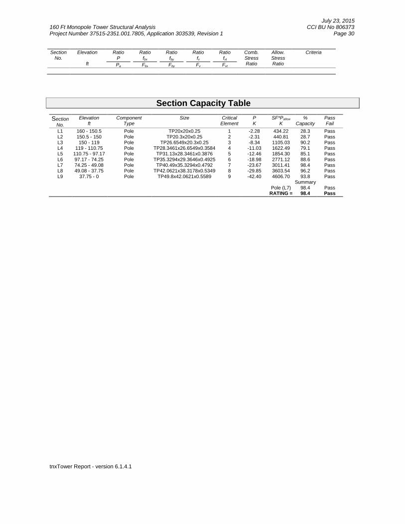
July 23, 2015160 Ft Monopole Tower Structural Analysis CCI BU No 806373Project Number 37515-2351.001.7805, Application 303539, Revision 1 Page 30
tnxTower Report - version 6.1.4.1
SectionNo.
Elevation
ft
RatioP
Pa
Ratiofbx
Fbx
Ratiofby
Fby
RatiofvFv
Ratiofvt
Fvt
Comb.StressRatio
Allow.StressRatio
Criteria
Section Capacity Table
SectionNo.
Elevationft
ComponentType
Size CriticalElement
PK
SF*Pallow
K%
CapacityPassFail
L1 160 - 150.5 Pole TP20x20x0.25 1 -2.28 434.22 28.3 PassL2 150.5 - 150 Pole TP20.3x20x0.25 2 -2.31 440.81 28.7 PassL3 150 - 119 Pole TP26.6549x20.3x0.25 3 -8.34 1105.03 90.2 PassL4 119 - 110.75 Pole TP28.3461x26.6549x0.3584 4 -11.03 1622.49 79.1 PassL5 110.75 - 97.17 Pole TP31.13x28.3461x0.3876 5 -12.46 1854.30 85.1 PassL6 97.17 - 74.25 Pole TP35.3294x29.3646x0.4925 6 -18.98 2771.12 88.6 PassL7 74.25 - 49.08 Pole TP40.49x35.3294x0.4792 7 -23.67 3011.41 98.4 PassL8 49.08 - 37.75 Pole TP42.0621x38.3178x0.5349 8 -29.85 3603.54 96.2 PassL9 37.75 - 0 Pole TP49.8x42.0621x0.5589 9 -42.40 4606.70 93.8 Pass
SummaryPole (L7) 98.4 Pass
RATING = 98.4 Pass

July 23, 2015160 Ft Monopole Tower Structural Analysis CCI BU No 806373Project Number 37515-2351.001.7805, Application 303539, Revision 1 Page 31
tnxTower Report - version 6.1.4.1
APPENDIX B
BASE LEVEL DRAWING

July 23, 2015160 Ft Monopole Tower Structural Analysis CCI BU No 806373Project Number 37515-2351.001.7805, Application 303539, Revision 1 Page 32
tnxTower Report - version 6.1.4.1

July 23, 2015160 Ft Monopole Tower Structural Analysis CCI BU No 806373Project Number 37515-2351.001.7805, Application 303539, Revision 1 Page 33
tnxTower Report - version 6.1.4.1
APPENDIX C
ADDITIONAL CALCULATIONS

Paul J. Ford and Company250 E. Broad Street, Suite 600
Columbus, OH 43215Phone: 614.221.6679
FAX: 614.448.4105
Job:160 ft Monopole / HRT 101 943232
Project: PJF 37515-2351 / BU 806373Client: Crown Castle Drawn by: Joey Meinerding App'd:
Code: TIA/EIA-222-F Date: 07/23/15 Scale: NTSPath:
T:\375_Crown_Castle\2015\37515-2351_806373_HRT 101 943232\37515-2351.001.7805_SA_1093654\37515-2351.001.7805_Reinforced.eri
Dwg No. E-1
160.0 ft
150.5 ft
119.0 ft
110.8 ft
97.2 ft
74.3 ft
49.1 ft
37.8 ft
0.0 ft
REACTIONS - 80.00 mph WINDTORQUE 2 kip-ft
39 KSHEAR
4276 kip-ftMOMENT
42 KAXIAL
37.60 mph WIND - 1.2500 in ICETORQUE 1 kip-ft
12 KSHEAR
1454 kip-ftMOMENT
85 KAXIAL
Section
12
34
56
78
9
Length
(ft)
9.5
000
0.5
000
31.0
000
8.2
500
13.5
800
27.7
500
25.1
700
17.2
500
37.7
500
Num
ber
of
Sid
es
11
12
12
12
12
12
12
12
Thic
kness
(in)
0.2
500
0.2
500
0.2
500
0.3
584
0.3
876
0.4
925
0.4
792
0.5
349
0.5
589
Socket
Length
(ft)
4.8
300
5.9
200
Top
Dia
(in)
20.0
000
20.0
000
20.3
000
26.6
549
28.3
461
29.3
646
35.3
294
38.3
177
42.0
621
Bot
Dia
(in)
20.0
000
20.3
000
26.6
549
28.3
461
31.1
300
35.3
294
40.4
900
42.0
621
49.8
000
Gra
de
A53-B
-35
A572-6
5R
ein
f62.8
0ksi
Rein
f62.4
3ksi
Rein
f62.7
1ksi
Rein
f62.8
9ksi
Rein
f62.9
9ksi
Rein
f65.0
0ksi
Weig
ht
(K)
0.5
0.0
2.0
0.9
1.7
4.8
4.9
4.0
10.5
29.3
SBNH-1D6565C w/ Mount Pipe 158SBNH-1D6565C w/ Mount Pipe 158SBNH-1D6565C w/ Mount Pipe 158(2) 7770.00 w/ Mount Pipe 158(2) 7770.00 w/ Mount Pipe 158(2) 7770.00 w/ Mount Pipe 158(2) LGP21401 158(2) LGP21401 158(2) LGP21401 158(2) LGP13519 158(2) LGP13519 158(2) LGP13519 158RRUS-11 158RRUS-11 158RRUS-11 158DC6-48-60-18-8F 158Platform Mount [LP 303-1] 158BXA-70063/6CFx6 w/ Mount Pipe 149BXA-70063/6CF w/ Mount Pipe 149BXA-70063/6CFx4 w/ Mount Pipe 149BXA-185063/8CF w/ Mount Pipe 149BXA-185090/8CFx2 w/ Mount Pipe 149BXA-185090/8CFx2 w/ Mount Pipe 149(2) LPA-80063/4CF w/ Mount Pipe 149(2) LPA-80080/4CF w/ Mount Pipe 149(2) LPA-80080/4CF w/ Mount Pipe 149742 213 w/ Mount Pipe 149742 213 w/ Mount Pipe 149742 213 w/ Mount Pipe 149(2) FD9R6004/2C-3L 149(2) FD9R6004/2C-3L 149(2) FD9R6004/2C-3L 149RRH2x40-AWS 149RRH2x40-AWS 149RRH2x40-AWS 149DB-T1-6Z-8AB-0Z 149Platform Mount [LP 602-1] 149800MHz 2X50W RRH W/FILTER 137800MHz 2X50W RRH W/FILTER 137800MHz 2X50W RRH W/FILTER 137PCS 1900MHz 4x45W-65MHz 137PCS 1900MHz 4x45W-65MHz 137PCS 1900MHz 4x45W-65MHz 137Side Arm Mount [SO 102-3] 137APXVSPP18-C-A20 w/ Mount Pipe 135APXV9ERR18-C-A20 w/ Mount Pipe 135APXVSPP18-C-A20 w/ Mount Pipe 135APXVTM14-C-120 w/ Mount Pipe 135APXVTM14-C-120 w/ Mount Pipe 135APXVTM14-C-120 w/ Mount Pipe 135TD-RRH8x20-25 135TD-RRH8x20-25 135TD-RRH8x20-25 135LLPX310R-V1 w/ Mount Pipe 135LLPX310R-V1 w/ Mount Pipe 135LLPX310R-V1 w/ Mount Pipe 135TIMING 2000 135WIMAX DAP HEAD 135WIMAX DAP HEAD 135WIMAX DAP HEAD 135HORIZON COMPACT 135Platform Mount [LP 602-1] 135VHLP2.5-11 135ERICSSON AIR 21 B4A B2P w/ MountPipe
116ERICSSON AIR 21 B4A B2P w/ MountPipe
116ERICSSON AIR 21 B2A B4P w/ MountPipe
116ERICSSON AIR 21 B2A B4P w/ MountPipe
116ERICSSON AIR 21 B2A B4P w/ MountPipe
116KRY 112 144/1 116KRY 112 144/1 116KRY 112 144/1 116LNX-6515DS-VTM w/ Mount Pipe 116LNX-6515DS-VTM w/ Mount Pipe 116LNX-6515DS-VTM w/ Mount Pipe 116RRUS 11 B12 116RRUS 11 B12 116RRUS 11 B12 1162.375" OD x 5' Mount Pipe 1162.375" OD x 5' Mount Pipe 1162.375" OD x 5' Mount Pipe 116T-Arm Mount [TA 602-3] 116ERICSSON AIR 21 B4A B2P w/ MountPipe
116Pipe Mount [PM 601-1] 5058532A 50Side Arm Mount [SO 701-1] 47KS24019-L112A 47DESIGNED APPURTENANCE LOADING
TYPE TYPEELEVATION ELEVATIONSBNH-1D6565C w/ Mount Pipe 158
SBNH-1D6565C w/ Mount Pipe 158
SBNH-1D6565C w/ Mount Pipe 158
(2) 7770.00 w/ Mount Pipe 158
(2) 7770.00 w/ Mount Pipe 158
(2) 7770.00 w/ Mount Pipe 158
(2) LGP21401 158
(2) LGP21401 158
(2) LGP21401 158
(2) LGP13519 158
(2) LGP13519 158
(2) LGP13519 158
RRUS-11 158
RRUS-11 158
RRUS-11 158
DC6-48-60-18-8F 158
Platform Mount [LP 303-1] 158
BXA-70063/6CFx6 w/ Mount Pipe 149
BXA-70063/6CF w/ Mount Pipe 149
BXA-70063/6CFx4 w/ Mount Pipe 149
BXA-185063/8CF w/ Mount Pipe 149
BXA-185090/8CFx2 w/ Mount Pipe 149
BXA-185090/8CFx2 w/ Mount Pipe 149
(2) LPA-80063/4CF w/ Mount Pipe 149
(2) LPA-80080/4CF w/ Mount Pipe 149
(2) LPA-80080/4CF w/ Mount Pipe 149
742 213 w/ Mount Pipe 149
742 213 w/ Mount Pipe 149
742 213 w/ Mount Pipe 149
(2) FD9R6004/2C-3L 149
(2) FD9R6004/2C-3L 149
(2) FD9R6004/2C-3L 149
RRH2x40-AWS 149
RRH2x40-AWS 149
RRH2x40-AWS 149
DB-T1-6Z-8AB-0Z 149
Platform Mount [LP 602-1] 149
800MHz 2X50W RRH W/FILTER 137
800MHz 2X50W RRH W/FILTER 137
800MHz 2X50W RRH W/FILTER 137
PCS 1900MHz 4x45W-65MHz 137
PCS 1900MHz 4x45W-65MHz 137
PCS 1900MHz 4x45W-65MHz 137
Side Arm Mount [SO 102-3] 137
APXVSPP18-C-A20 w/ Mount Pipe 135
APXV9ERR18-C-A20 w/ Mount Pipe 135
APXVSPP18-C-A20 w/ Mount Pipe 135
APXVTM14-C-120 w/ Mount Pipe 135
APXVTM14-C-120 w/ Mount Pipe 135
APXVTM14-C-120 w/ Mount Pipe 135
TD-RRH8x20-25 135
TD-RRH8x20-25 135
TD-RRH8x20-25 135
LLPX310R-V1 w/ Mount Pipe 135
LLPX310R-V1 w/ Mount Pipe 135
LLPX310R-V1 w/ Mount Pipe 135
TIMING 2000 135
WIMAX DAP HEAD 135
WIMAX DAP HEAD 135
WIMAX DAP HEAD 135
HORIZON COMPACT 135
Platform Mount [LP 602-1] 135
VHLP2.5-11 135
ERICSSON AIR 21 B4A B2P w/ MountPipe
116
ERICSSON AIR 21 B4A B2P w/ MountPipe
116
ERICSSON AIR 21 B2A B4P w/ MountPipe
116
ERICSSON AIR 21 B2A B4P w/ MountPipe
116
ERICSSON AIR 21 B2A B4P w/ MountPipe
116
KRY 112 144/1 116
KRY 112 144/1 116
KRY 112 144/1 116
LNX-6515DS-VTM w/ Mount Pipe 116
LNX-6515DS-VTM w/ Mount Pipe 116
LNX-6515DS-VTM w/ Mount Pipe 116
RRUS 11 B12 116
RRUS 11 B12 116
RRUS 11 B12 116
2.375" OD x 5' Mount Pipe 116
2.375" OD x 5' Mount Pipe 116
2.375" OD x 5' Mount Pipe 116
Site Pro - RMV12-396 116
ERICSSON AIR 21 B4A B2P w/ MountPipe
116
Pipe Mount [PM 601-1] 50
58532A 50
Side Arm Mount [SO 701-1] 47
KS24019-L112A 47
MATERIAL STRENGTHGRADE GRADEFy FyFu Fu
A53-B-35 35 ksi 60 ksi
A572-65 65 ksi 80 ksi
Reinf 62.80 ksi 63 ksi 79 ksi
Reinf 62.43 ksi 62 ksi 79 ksi
Reinf 62.71 ksi 63 ksi 79 ksi
Reinf 62.89 ksi 63 ksi 79 ksi
Reinf 62.99 ksi 63 ksi 79 ksi
Reinf 65.00 ksi 65 ksi 82 ksi
TOWER DESIGN NOTES1. Tower is located in Hartford County, Connecticut.2. Tower designed for a 80.00 mph basic wind in accordance with the TIA/EIA-222-F Standard.3. Tower is also designed for a 37.60 mph basic wind with 1.25 in ice. Ice is considered to increase in
thickness with height.4. Deflections are based upon a 50.00 mph wind.5. TOWER RATING: 98.4%

Date:
PJF Project:
Client Ref. #
Site Name:
Description:
Owner:
v4.4 - Effective 7-12-13 Engineer:
Moment = 4276 k-ft TIA Ref. F Location = Base Plate
Axial = 42.0 kips ASIF = 1.3333 η = N/A for BP, Rev. G Sect. 4.9.9
Shear = 39.0 kips Max Ratio = 105.0% Threads = N/A for FP, Rev. G
Anchor Qty = 19
Item
Nominal
Anchor Dia,
in Spec Fy, ksi Fu, ksi
Location,
degrees
Anchor
Circle, in
Area
Override,
in2 Area, in2
Max Net
Compressio
n, kips
Max Net
Tension,
kips
Load for
Capacity
Calc, kips
Capacity
Override,
kips
Capacity,
kips
Capacity
Ratio
1 2.250 #18J A615 Gr 75 75 100 0.0 58.06 0.00 3.98 183.36 178.94 178.94 0.00 195.00 91.8%
2 2.250 #18J A615 Gr 75 75 100 22.5 58.06 0.00 3.98 180.06 175.64 175.64 0.00 195.00 90.1%
3 2.250 #18J A615 Gr 75 75 100 45.0 58.06 0.00 3.98 178.94 174.52 174.52 0.00 195.00 89.5%
4 2.250 #18J A615 Gr 75 75 100 67.5 58.06 0.00 3.98 180.30 175.87 175.87 0.00 195.00 90.2%
5 2.250 #18J A615 Gr 75 75 100 90.0 58.06 0.00 3.98 182.92 178.50 178.50 0.00 195.00 91.5%
6 2.250 #18J A615 Gr 75 75 100 112.5 58.06 0.00 3.98 184.97 180.55 180.55 0.00 195.00 92.6%
7 2.250 #18J A615 Gr 75 75 100 135.0 58.06 0.00 3.98 185.11 180.69 180.69 0.00 195.00 92.7%
8 2.250 #18J A615 Gr 75 75 100 157.5 58.06 0.00 3.98 183.26 178.84 178.84 0.00 195.00 91.7%
9 2.250 #18J A615 Gr 75 75 100 180.0 58.06 0.00 3.98 180.61 176.19 176.19 0.00 195.00 90.4%
10 2.250 #18J A615 Gr 75 75 100 202.5 58.06 0.00 3.98 178.99 174.57 174.57 0.00 195.00 89.5%
11 2.250 #18J A615 Gr 75 75 100 225.0 58.06 0.00 3.98 179.76 175.34 175.34 0.00 195.00 89.9%
12 2.250 #18J A615 Gr 75 75 100 247.5 58.06 0.00 3.98 182.85 178.42 178.42 0.00 195.00 91.5%
13 2.250 #18J A615 Gr 75 75 100 270.0 58.06 0.00 3.98 186.75 182.33 182.33 0.00 195.00 93.5%
14 2.250 #18J A615 Gr 75 75 100 292.5 58.06 0.00 3.98 189.49 185.07 185.07 0.00 195.00 94.9%
15 2.250 #18J A615 Gr 75 75 100 315.0 58.06 0.00 3.98 189.68 185.26 185.26 0.00 195.00 95.0%
16 2.250 #18J A615 Gr 75 75 100 337.5 58.06 0.00 3.98 187.23 182.80 182.80 0.00 195.00 93.7%
17 2.250 A193 Gr B7 105 125 12.3 63.00 0.00 3.98 196.34 191.92 191.92 0.00 218.68 87.8%
18 2.250 A193 Gr B7 105 125 125.3 63.00 0.00 3.98 200.90 196.48 196.48 0.00 218.68 89.8%
19 2.250 A193 Gr B7 105 125 238.3 63.00 0.00 3.98 196.34 191.92 191.92 0.00 218.68 87.8%
75.61
Asymmetric Anchor Rod Analysis
160' Pole
Crown Castle
JWM
** For Post Installed Anchors: Check anchors for embedment, epoxy/grout bond, and capacity based on proof load. **
7/23/2015
37515-2351.001.7805
806373
HRT 101 943232
© Copyright 2011, Paul J. Ford and Company, all right reserved.

TIA Rev FSite Data Reactions
BU#: Moment: 3628.1 ft-kips
Site Name: Axial: 35.4 kips
App #: Shear: 32.8 kips
Other
If No stiffeners, Criteria: AISC ASD <-Only Applcable to Unstiffened Cases
Qty: 16
Diam: 2.25 in
Rod Material: A615-J Anchor Rod Results Rigid
Strength (Fu): 100 ksi Maximum Rod Tension: 185.3 Kips Service, ASD
Yield (Fy): 75 ksi Allowable Tension: 195.0 Kips Fty*ASIF
Bolt Circle: 58.06 in Anchor Rod Stress Ratio: 95.0% Pass
Diam: 64.06 in Base Plate Results Flexural Check Rigid
Thick: 2.75 in Base Plate Stress: 38.7 ksi Service ASD
Grade: 60 ksi Allowable Plate Stress: 60.0 ksi 0.75*Fy*ASIF
Single-Rod B-eff: 10.01 in Base Plate Stress Ratio: 64.6% Pass Y.L. Length:
29.85
n/a
Config: 0 * Stiffener ResultsWeld Type: Horizontal Weld : n/a
Groove Depth: in ** Vertical Weld: n/a
Groove Angle: degrees Plate Flex+Shear, fb/Fb+(fv/Fv)^2: n/a
Fillet H. Weld: <-- Disregard Plate Tension+Shear, ft/Ft+(fv/Fv)^2: n/a
Fillet V. Weld: in Plate Comp. (AISC Bracket): n/a
Width: in
Height: in Pole ResultsThick: in Pole Punching Shear Check: n/a
Notch: in
Grade: ksi
Weld str.: ksi
Diam: 49.8 in
Thick: 0.4375 in
Grade: 65 ksi
# of Sides: 12 "0" IF Round
Fu 80 ksi
Reinf. Fillet Weld 0 "0" if None
ASIF: 1.333
* 0 = none, 1 = every bolt, 2 = every 2 bolts, 3 = 2 per bolt
** Note: for complete joint penetration groove welds the groove depth must be exactly 1/2 the stiffener thickness for calculation purposes
Pole Manufacturer:
Stiffened or Unstiffened, Ungrouted, Circular Base Plate - Any Rod Material
Stress Increase Factor
Pole Data
Anchor Rod Data
Plate Data
Stiffener Data (Welding at both sides)
806373
HRT 101 943232
Reactions adjusted to
account for additional
anchor rods.
CCIplate 1.5 - Circular Base F 1.2, Effective March 19, 2012 Analysis Date: 7/23/2015

Job Number: 37515-2351.001.7805 Page: 1
Site Number: 806373 By: JWM
Site Name: HRT 101 943232 Date: 7/23/2015
Unfactored Base Reactions from RISA Safety Factors / Load Factors / Φ FactorsComp. (+) Tension (-) Tower Type = Monopole DP
Moment, M = 4276.0 k-ft ACI Code = ACI 318-02
Shear, V = 39.0 kips Seismic Design Category = D
Axial Load, P = 42.0 kips Reference Standard = TIA/EIA-222-F
Axial Load, P = 42.0 0.0 kips Use 1.3 Load Factor? Yes
OTM = 4315.0 0.0 k-ft @ Ground Load Factor = 1.30
*Axial Load, Pu1 will be used for Soil Compression Analysis.
**Axial Load, Pu2 will be used for Steel Analysis.
Drilled Pier Parameters Safety Factor Φ Factor
Diameter = 7 ft Soil Lateral Resistance = 2.00 0.75
Height Above Grade = 1 ft Skin Friction = 2.00 0.75
Depth Below Grade = 24.5 ft End Bearing = 2.00 0.75
fc' = 3 ksi Concrete Wt. Resist Uplift = 1.25
εc = 0.003 in/in
Load Combinations Checked per TIA/EIA-222-FMat Ftdn. Cap Width = ft 1. Ult. Skin Friction/2.00 + Ult. End Bearing/2.00
Mat Ftdn. Cap Length = ft + Effective Soil Wt. - Buoyant Conc. Wt. ≥ Comp.
Depth Below Grade = ft 2. Ult. Skin Friction/2.00 + Buoyant Conc. Wt./1.25 ≥ Uplift
3. Ult. Skin Friction/1.50 + Buoyant Conc. Wt./1.50 ≥ Uplift
Steel Parameters Soil ParametersNumber of Bars = 36 Water Table Depth = 4.00 ft
Rebar Size = #11 Depth to Ignore Soil = 3.50 ft
Rebar Fy = 60 ksi Depth to Full Cohesion = 0 ft
Rebar MOE = 29000 ksi Full Cohesion Starts at? Ground
Tie Size = #4 Above Full Cohesion Lateral Resistance = 4(Cohesion)(Dia)(H)
Side Clear Cover to Ties = 3 in Below Full Cohesion Lateral Resistance = 8(Cohesion)(Dia)(H)
Direct Embed Pole Shaft Parameters Maximum Capacity RatiosDia @ Grade = in Maximum Soil Ratio = 110.0%
Dia @ Depth Below Grade = in Maximum Steel Ratio = 105.0%
Number of Sides =
Thickness = in
Fy = ksi
Backfill Condition =
Define Soil LayersNote: Cohesion = Undrained Shear Strengh = Unconfined Compressive Strength / 2
Friction Ultimate Comp. Ult. Tension Ult.
Thickness Unit Weight Cohesion Angle End Bearing Skin Friction Skin Friction Depth
Layer ft pcf psf degrees Soil Type psf psf psf ft
1 4 120 0 28 Sand 4
2 1 125 0 42 Sand 5
3 19.5 127.4 0 42 Sand 17000 24.5
4
5
6
7
8
9
10
11
12
Soil Results: OverturningDepth to COR = 17.30 ft, from Grade Shear, V = 39.00 kips
Bending Moment, M = 4989.70 k-ft, from COR Resisting Shear, Va = 46.49 kips
Resisting Moment, Ma = 5947.97 k-ft, from COR
Soil Results: Uplift Soil Results: CompressionUplift, T = 0.00 kips Compression, C = 42.00 kips
Allowable Uplift Cap., Ta = 78.38 kips Allowable Comp. Cap., Ca = 298.81 kips
Steel Results (ACI 318-02):Minimum Steel Area = 18.47 sq in Axial Load, P = 75.08 kips @ 5.25 ft Below Grade
Actual Steel Area = 56.16 sq in Moment, M = 4493.98 k-ft @ 5.25 ft Below Grade
Allowable Moment, Ma = 6563.52 k-ft
Allowable Min Axial, Pa = -2332.80 kips, Where Ma = 0 k-ft
Allowable Max Axial, Pa = 6943.16 kips, Where Ma = 0 k-ftMOMENT RATIO = 68.5% OK
DRILLED PIER SOIL AND STEEL ANALYSIS - TIA/EIA-222-F
SHEAR RATIO = 83.9% OKMOMENT RATIO = 83.9% OK
OKUPLIFT RATIO = 0.0% OK COMPRESSION RATIO = 14.1%
v4.0 - Effective: 10-18-13 (c) Copyright 2013 by Paul J. Ford and Company, all rights reserved.

Site Data
BU#: F
Site Name: 4493.98 ft-kips (* Note)
App #: 75.08 kips
Comp.
For M (WL) 1.3 <---- Enter Factor
For P (DL) 1.3 <---- Enter Factor Load Factor
1.30 Mu: 5842.174 ft-kips
1.30 Pu: 97.604 kips
Concrete:7.0 ft
5541.8 in2
3000 psi
60 ksi
Reinforcement: 29000 ksi
3.00 in 0.00207
Horiz. Tie Bar Size= 4 0.003
6.30 ft
75.59 in 2002
11
1.41 in D
1.56 in2
Seismic Risk = High36
As Total= 56.16 in2
Solve <-- Press Upon Completing All Input
A s/ Aconc, Rho: 0.0101 1.01% (Run)
ACI 10.5 , ACI 21.10.4, and IBC 1810. Results:Min As for Flexural, Tension Controlled, Shafts: Governing Orientation Case: 2
(3)*(Sqrt(f'c)/Fy: 0.0027
200 / Fy: 0.0033
Dist. From Edge to Neutral Axis: 17.62 in
Extreme Steel Strain, єt: 0.0106Minimum Rho Check:
Actual Req'd Min. Rho: 0.33% Flexural Reduction Factor,φ: 0.900Provided Rho: 1.01% OK
Ref. Shaft Max Axial Capacities, φ Max(Pn or Tn):
Output Note: Negative Pu=Tension
9026.11 kips For Axial Compression, φ Pn = Pu: 97.60 kips5472.88 ft-kips Drilled Shaft Moment Capacity, φMn: 8532.58 ft-kips
Drilled Shaft Superimposed Mu: 5842.17 ft-kips
3032.64 kips
0.00 ft-kips 68.5%
Case 1 Case 2
Limiting compressive strain =
Vertical Bar Size = Seismic PropertiesBar Diameter =
Material Properties
Number of Bars =
Vert. Cage Diameter =
Max Tu, (φ=0.9) Tn =at Mu=φ=(0.90)Mn=
at Mu=(φ=0.65)Mn=
Max Pu = (φ=0.65) Pn. Pn per ACI 318 (10-2)
(Mu/φMn, Drilled Shaft Flexure CSR:
єt > 0.0050, Tension Controlled
Seismic Design Category =
Vert. Cage Diameter =
Enter Load Factors Below:
Shaft Factored Loads
Bar Area =
Pier Properties
Pier Diameter =
Concrete Comp. strength, f'c =
Reinforcement yield strength, Fy =
Concrete Area =
Moment Capacity of Drilled Concrete Shaft (Caisson) for TIA Rev F or G
TIA Revision:
Max. Service Shaft M:
Max. Service Shaft P:
Maximum Shaft Superimposed Forces
Max Axial Force Type:
ACI 318 CodeSelect Analysis ACI Code=
Note: Shaft assumed to have ties, not spiral, transverse reinforcing
Reinforcing Modulus of Elasticity, E =
Reinforcement yield strain =
806373HRT 101 943232
(*) Note: Max Shaft Superimposed Moment does not necessarily
equal to the shaft top reaction moment
Clear Cover to Tie=
Mu Mu
EQ EQ
Drilled_Shaft_Moment_Capacity, DSMC, Version 1.1 - Effective 04/01/ 2010 Analysis Date: 7/23/2015

EBI Consulting environmental | engineering | due diligence
21 B Street . Burlington, MA 01803 . Tel: (781) 273.2500 . Fax: (781) 273.3311
RADIO FREQUENCY EMISSIONS ANALYSIS REPORT EVALUATION OF HUMAN EXPOSURE POTENTIAL
TO NON-IONIZING EMISSIONS
T-Mobile Existing Facility
Site ID: CT11066A
CT11066A_Enfield_I-91_X47 4 Oliver Road
Enfield, CT 06082
August 13, 2015
EBI Project Number: 6215004333
Site Compliance Summary
Compliance Status: COMPLIANT
Site total MPE% of FCC general public
allowable limit: 66.96 %

EBI Consulting environmental | engineering | due diligence
21 B Street . Burlington, MA 01803 . Tel: (781) 273.2500 . Fax: (781) 273.3311
August 13, 2015
T-Mobile USA Attn: Jason Overbey, RF Manager 35 Griffin Road South Bloomfield, CT 06002
Emissions Analysis for Site: CT11066A – CT11066A_Enfield_I-91_X47
EBI Consulting was directed to analyze the proposed T-Mobile facility located at 4 Oliver Road, Enfield, CT, for the purpose of determining whether the emissions from the Proposed T-Mobile Antenna Installation located on this property are within specified federal limits.
All information used in this report was analyzed as a percentage of current Maximum Permissible Exposure (% MPE) as listed in the FCC OET Bulletin 65 Edition 97-01and ANSI/IEEE Std C95.1. The FCC regulates Maximum Permissible Exposure in units of microwatts per square centimeter (µW/cm2). The number of µW/cm2 calculated at each sample point is called the power density. The exposure limit for power density varies depending upon the frequencies being utilized. Wireless Carriers and Paging Services use different frequency bands each with different exposure limits, therefore it is necessary to report results and limits in terms of percent MPE rather than power density.
All results were compared to the FCC (Federal Communications Commission) radio frequency exposure rules, 47 CFR 1.1307(b)(1) – (b)(3), to determine compliance with the Maximum Permissible Exposure (MPE) limits for General Population/Uncontrolled environments as defined below.
General population/uncontrolled exposure limits apply to situations in which the general public may be exposed or in which persons who are exposed as a consequence of their employment may not be made fully aware of the potential for exposure or cannot exercise control over their exposure. Therefore, members of the general public would always be considered under this category when exposure is not employment related, for example, in the case of a telecommunications tower that exposes persons in a nearby residential area.
Public exposure to radio frequencies is regulated and enforced in units of microwatts per square centimeter (μW/cm2). The general population exposure limit for the 700 MHz Band is approximately 467 μW/cm2, and the general population exposure limit for the PCS and AWS bands is 1000 μW/cm2. Because each carrier will be using different frequency bands, and each frequency band has different exposure limits, it is necessary to report percent of MPE rather than power density.

EBI Consulting environmental | engineering | due diligence
21 B Street . Burlington, MA 01803 . Tel: (781) 273.2500 . Fax: (781) 273.3311
Occupational/controlled exposure limits apply to situations in which persons are exposed as a consequence of their employment and in which those persons who are exposed have been made fully aware of the potential for exposure and can exercise control over their exposure. Occupational/controlled exposure limits also apply where exposure is of a transient nature as a result of incidental passage through a location where exposure levels may be above general population/uncontrolled limits (see below), as long as the exposed person has been made fully aware of the potential for exposure and can exercise control over his or her exposure by leaving the area or by some other appropriate means.
Additional details can be found in FCC OET 65.
CALCULATIONS
Calculations were done for the proposed T-Mobile Wireless antenna facility located at 4 Oliver Road, Enfield, CT, using the equipment information listed below. All calculations were performed per the specifications under FCC OET 65. Since T-Mobile is proposing highly focused directional panel antennas, which project most of the emitted energy out toward the horizon, all calculations were performed assuming a lobe representing the maximum gain of the antenna per the antenna manufactures supplied specifications, minus 10 dB, was focused at the base of the tower. For this report the sample point is the top of a 6 foot person standing at the base of the tower.
For all calculations, all equipment was calculated using the following assumptions:
1) 2 GSM channels (PCS Band - 1900 MHz) were considered for each sector of the proposed installation. These Channels have a transmit power of 30 Watts per Channel
2) 2 UMTS channels (AWS Band – 2100 MHz) were considered for each sector of the proposed installation. These Channels have a transmit power of 30 Watts per Channel.
3) 2 LTE channels (AWS Band – 2100 MHz) were considered for each sector of the proposed
installation. These Channels have a transmit power of 60 Watts per Channel. 4) 1 LTE channel (700 MHz Band) was considered for each sector of the proposed installation.
This channel has a transmit power of 30 Watts. 5) All radios at the proposed installation were considered to be running at full power and were
uncombined in their RF transmissions paths per carrier prescribed configuration. Per FCC OET Bulletin No. 65 - Edition 97-01 recommendations to achieve the maximum anticipated value at each sample point, all power levels emitting from the proposed antenna installation are increased by a factor of 2.56 to account for possible in-phase reflections from the surrounding environment. This is rarely the case, and if so, is never continuous.

EBI Consulting environmental | engineering | due diligence
21 B Street . Burlington, MA 01803 . Tel: (781) 273.2500 . Fax: (781) 273.3311
6) For the following calculations the sample point was the top of a six foot person standing at the base of the tower. The maximum gain of the antenna per the antenna manufactures supplied specifications minus 10 dB was used in this direction. This value is a very conservative estimate as gain reductions for these particular antennas are typically much higher in this direction.
7) The antennas used in this modeling are the Ericsson AIR21 B4A/B2P & B2A/B4P) for 1900 MHz (PCS) and 2100 MHz (AWS) channels and the Commscope LNX-6515DS-VTM for 700 MHz channels. This is based on feedback from the carrier with regards to anticipated antenna selection. The Ericsson AIR21 B4A/B2P. The Commscope LNX-6515DS-VTM has a maximum gain of 14.6 dBd at its main lobe. The maximum gain of the antenna per the antenna manufactures supplied specifications, minus 10 dB, was used for all calculations. This value is a very conservative estimate as gain reductions for these particular antennas are typically much higher in this direction.
8) The antenna mounting height centerline of the proposed antennas is 117 feet above ground level (AGL).
9) Emissions values for additional carriers were taken from the Connecticut Siting Council
active database. Values in this database are provided by the individual carriers themselves.
All calculations were done with respect to uncontrolled / general public threshold limits.

EBI Consulting environmental | engineering | due diligence
21 B Street . Burlington, MA 01803 . Tel: (781) 273.2500 . Fax: (781) 273.3311
T-Mobile Site Inventory and Power Data
Sector: A Sector: B Sector: C Antenna #: 1 Antenna #: 1 Antenna #: 1
Make / Model: Ericsson AIR21 B4A/B2P Make / Model: Ericsson AIR21
B4A/B2P Make / Model: Ericsson AIR21 B4A/B2P
Gain: 15.9 dBd Gain: 15.9 dBd Gain: 15.9 dBd Height (AGL): 117 Height (AGL): 117 Height (AGL): 117
Frequency Bands 1900 MHz(PCS) / 2100 MHz (AWS) Frequency Bands 1900 MHz(PCS) /
2100 MHz (AWS) Frequency Bands 1900 MHz(PCS) / 2100 MHz (AWS)
Channel Count 2 Channel Count 2 # PCS Channels: 2 Total TX Power: 120 Total TX Power: 120 # AWS Channels: 120
ERP (W): 4,668.54 ERP (W): 4,668.54 ERP (W): 4,668.54 Antenna A1 MPE% 1.36 Antenna B1 MPE% 1.36 Antenna C1 MPE% 1.36
Antenna #: 2 Antenna #: 2 Antenna #: 2
Make / Model: Ericsson AIR21 B2A/B4P Make / Model: Ericsson AIR21
B2A/B4P Make / Model: Ericsson AIR21 B2A/B4P
Gain: 15.9 dBd Gain: 15.9 dBd Gain: 15.9 dBd Height (AGL): 117 Height (AGL): 117 Height (AGL): 117
Frequency Bands 1900 MHz(PCS) / 2100 MHz (AWS) Frequency Bands 1900 MHz(PCS) /
2100 MHz (AWS) Frequency Bands 1900 MHz(PCS) / 2100 MHz (AWS)
Channel Count 4 Channel Count 4 Channel Count 4 Total TX Power: 120 Total TX Power: 120 Total TX Power: 120
ERP (W): 4,668.54 ERP (W): 4,668.54 ERP (W): 4,668.54 Antenna A2 MPE% 1.36 Antenna B2 MPE% 1.36 Antenna C2 MPE% 1.36
Antenna #: 3 Antenna #: 3 Antenna #: 3
Make / Model: Commscope LNX-6515DS-VTM Make / Model: Commscope LNX-
6515DS-VTM Make / Model: Commscope LNX-6515DS-VTM
Gain: 14.6 dBd Gain: 14.6 dBd Gain: 14.6 dBd Height (AGL): 117 Height (AGL): 117 Height (AGL): 117
Frequency Bands 700 MHz Frequency Bands 700 MHz Frequency Bands 700 MHz Channel Count 1 Channel Count 1 Channel Count 1
Total TX Power: 30 Total TX Power: 30 Total TX Power: 30 ERP (W): 865.21 ERP (W): 865.21 ERP (W): 865.21
Antenna A3 MPE% 0.54 Antenna B3 MPE% 0.54 Antenna C3 MPE% 0.54
Site Composite MPE% Carrier MPE%
T-Mobile 9.79 AT&T 12.74 %
Verizon Wireless 23.47 % Clearwire 0.98 % MetroPCS 10.82 %
Sprint 3.51 % Nextel 2.03 %
XM Satellite Radio 1.17 % PageNet 2.45 %
Site Total MPE %: 66.96 %
T-Mobile Sector 1 Total: 3.26 % T-Mobile Sector 2 Total: 3.26 % T-Mobile Sector 3 Total: 3.26 %
Site Total: 66.96 %

EBI Consulting environmental | engineering | due diligence
21 B Street . Burlington, MA 01803 . Tel: (781) 273.2500 . Fax: (781) 273.3311
Summary
All calculations performed for this analysis yielded results that were within the allowable limits for general public exposure to RF Emissions.
The anticipated maximum composite contributions from the T-Mobile facility as well as the site composite emissions value with regards to compliance with FCC’s allowable limits for general public exposure to RF Emissions are shown here:
T-Mobile Sector Power Density Value (%) Sector 1: 3.26 % Sector 2: 3.26 % Sector 3 : 3.26 %
T-Mobile Total: 9.79 %
Site Total: 66.96 %
Site Compliance Status: COMPLIANT
The anticipated composite MPE value for this site assuming all carriers present is 66.96% of the allowable FCC established general public limit sampled at the ground level. This is based upon values listed in the Connecticut Siting Council database for existing carrier emissions.
FCC guidelines state that if a site is found to be out of compliance (over allowable thresholds), that carriers over a 5% contribution to the composite value will require measures to bring the site into compliance. For this facility, the composite values calculated were well within the allowable 100% threshold standard per the federal government.
Scott Heffernan RF Engineering Director EBI Consulting 21 B Street Burlington, MA 01803
Top Related