


Languages
Pages
Legal


system
System with pre-insulated pipesfor district heating & cooling (DHC)

Introduction
Easy installation
Energy saving
Components of the systemPre-insulated internal service pipes for DHW (Domestic Hot Water) systemsPre-insulated internal service pipes for mechanical-thermal systems
Allowed working pressuresDomestic water systemsClosed-circuit, heating, air-conditioning, and remote heating systems
sistema
System with pre-insulated pipesfor district heating & cooling (DHC)
2
3
4
5
6
7
8
8
9
10
1414
1515
1.1Item list
General recommendations about overhead installations with bracket-type collarsTable about clamping units for overhead installations
General recommendations about the installation inside a ditch (burial)Typical heights in an excavation
Instructions regarding the flame relevant to weather conditions 13
Instructions to process the single- and double-seal restoration joint
Insulation dimensional features of pipes and fittings
Features of external PEHD casing pipe
Features of PUR insulation
Comparison table

Introduction
2
The iso-technik system, which is designed and manufactured by Aquatechnik Group S.P.A., includes a complete range of pre-insulated fittings and single pipes made with PUR (stiff polyurethane) foam protected by a casing pipe made with PEHD.The iso-technik system is used to remotely distribute energy, both directly and indirectly, by means of the carrying fluid - water.The range of diameters provides for the sizes included between Ø 32 and 250 mm, made with SDR 7.4 and SDR 11, which are available in the following versions:·
iso fiber-T (for domestic water uses)iso fiber-COND (for mechanical uses)
The products are guaranteed with integrated cycle and comply with the standards that regulate the industry: EN 253, EN 488, EN 489, DIN 8075, and UNI EN ISO 15874.
Internal service pipes and fittings, which form the iso-technik system, are made with completely synthetic material, with a state-of-the-art polypropylene-based technopolymer Super PP-R 80 with compounding fibre-reinforced matrix (GFRP).(Polypropylene random tested MRS 100 + compounding fibre-reinforced)
The remote transfer of energy between thermal power stations for the production of heat, chillers/heat pumps, geothermal systems, thermal-bath systems, etc. and the utilities of the users provides for networks of pre-insulated buried pipes that assure maximum safety and design/application reliability.
Thanks to Aquatechnik's well-established know-how, compliance with the standards in force about this matter and strict in-house disciplinary measures attested by the corporate certification, the pre-insulated pipes of the iso-technik system were conceived with specific burial installation and self-compensating expansion features. The high quality standards of the system are obtained thanks to the high quality of the materials being used and to the most advanced integrated production technologies, which mainly refer to service pipes with high mechanical stabilization and reduced expansion (made with PP-R 80 super, tested MRS 100) together with the "bonded" type system, which restrains the high-quality PUR heat insulator until obtaining a compact system between the external PEHD 80 casing pipe (treated with hot corona discharge) and the service pipes.

Easy installation
3
The iso-technik system is characterised by several advantages:
Easy installation, quick application and safe system junctions by means of hot-melt sealing M/F from Ø 32 to 125 mm, pressure welding (butt type) from Ø 160 to 250 mm and electric sleeve.
Dedicated welding equipment, with welding machines that mechanically self-align the pipes (from Ø 50 to 250 mm). No crane hoists and/or similar devices are needed to handle the items during the welding operation.
Reduced linear mass with respect to metal pipes, so it is easier to manoeuvre the materials on the spot. It is not necessary to perform crosswise weld cutting.
Selection of single- and/or double-seal restoration joints to be carried out by means of on-site foaming by using a PUR bicomponent material (isocyanate and polyol).
Facilitated operation both to cut the service pipe and to remove the heat insulator and the casing pipe, in order to remove the shell from the pipe for customised installation.
Opportunity to assembly the line out of the ditch and re-positioning into the ditch afterwards; it is very useful in case of very bad weather conditions that make the ditch unusable.
In case there are no direction changes by means of “cold” installation, the iso-technik system offers excellent self-compensation in the expansion (only in case of buried installations). So, it is not necessary to provide for loops, omegas, disposable mechanical compensators, thrust bearings, and all the solutions that increase work costs.
The very low thrust force, expansion axial stress (s) of the system (Kgf /N) allows, the possible installation in "pre-tension" with open ditch, which consists in preheating the lines with temperatures that reach at least 50% of the max. design temperature before being buried to close the excavation.
The tensions caused by residual thermal expansions will be absorbed and compensated in a natural way by the material, and the plastic features of the same material will allow finding a new outline of the pipe. According to what is said above, the exercised thrust forces (s) are calculated according to the features of the modulus of elasticity of the materials.
As for the above-mentioned values, we can infer a higher stress in steel compared with fibre-reinforced PP-R, where it is remarkably lower. For more information, please contact our Technical Dep.
Modulus of elasticity (σ= Sigma) Expansion coefficient (Kˉ¹)
PP-r 900 N/mm² = Kgfˑm 81.6 α 0,035 mm/m°C
PP-r 900 N/mm² = Kgfˑm 81.6Steel 210.000 N/mm² = Kgfˑm 21.400 α 0,0115 mm/m°C
PP-R 900 N/mm² = Kgfˑm 81.6

Energy saving
4
The iso-technik system is characterised by several energy saving advantages, as well:
It is considered "energy saving" thanks to its intrinsic features of very low thermal conductivity. Its thermal performance can be compared with series 1 of metal pre-insulated pipes, which provide for an increased heat insulator thickness category.
Minimum linear heat loss thanks to the low thermal conductivity coefficient U (W/m°C) values, also in the presence of high heat gradients (ΔΤ); this factor is mainly characterised by the very low thermal conductivity of the service pipe equalling only 0.24 W/mK. Together with an excellent and uniform insulation by means of stiff polyurethane foam (PUR) injected into the interspace with annular cross-section between the service pipe and the external casing pipe (PEHD), it makes the pipes highly efficient from the energy saving point of view (conductivity reference value for steel equalling 45 W/mK ).
So, thanks to the use of our iso-technik system, we can certify that energy savings reach values included between 8% and 10% compared with the use of pre-insulated metal pipes of the normal range.
The low internal friction of the pipe allows the laminar flow of the fluid thanks to the mirror-like surface, whose roughness equals 0.070µ, with subsequent low distributed pressure drops. This way, the energy consumption of circulation pumps is only proportioned to the hydrostatic pressure head (h/m) as regards the design flow-rate (Q), thus assuring minimum speeds of heat-carrying fluids, without creating turbulences.
Increased system cleanliness: the iso-technik system does not create sludge, rust, and remarkably reduces scale deposits; the aforesaid factors lead to a poor performance of the system with possible clogging problems concerning exchangers, filters, shut-off valves and other devices that form the plant-engineering of the users, and the need for frequent maintenance interventions.
The iso-technik system does not need corrosion-resistant film-forming treatments; in addition, it is compatible with antifreeze products, ethylene glycol and propylene glycol types, and resists the main chemical components
No corrosion phenomena caused by:Stress corrosion due to bimetallic couplings between different metal alloys.Leakage, direct and alternating currents, so it is not necessary to provide for any cathode-anodic protection because the fibre-reinforced PP-R pipe is characterised by a low electrical conductivity equalling >OhmΩ 10 cm.
External corrosion of the service pipe caused by watering as the dew point has been reached.For thermal water and fluids that contain sulphide, bromine, etc.Oxygenation in the system, ex. water restoration in thermal systems
low thermal conductivityexcellent and homogeneous insulation
8%-10% energy savingsexcellent fluid flow
increased system cleanlinessno corrosion phenomena
Components of the iso-technik system
Internal pre-insulated service pipes for DHW (Domestic Hot Water) systems
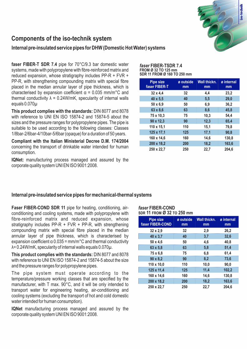
faser FIBER-T SDR 7.4 pipe for 70°C/9.3 bar domestic water systems, made with polypropylene with fibre-reinforced matrix and reduced expansion, whose stratigraphy includes PP-R + FVR + PP-R, with strengthening compounding matrix with special fibre placed in the median annular layer of pipe thickness, which is characterised by expansion coefficient α = 0.035 mm/m°C and thermal conductivity λ = 0.24W/mK, specularity of internal walls equals 0.070µ
This product complies with the standards: DIN 8077 and 8078 with reference to UNI EN ISO 15874-2 and 15874-5 about the sizes and the pressure ranges for polypropylene pipes. The pipe is suitable to be used according to the following classes: Classes 1/8bar-2/6bar-4/10bar-5/6bar (opaque) for a duration of 50 years.
Compliant with the Italian Ministerial Decree D.M. 174/2004 concerning the transport of drinkable water intended for human consumption.
IQNet: manufacturing process managed and assured by the corporate quality system UNI EN ISO 9001:2008.
faser FIBER-TSDR 7.4 FROM Ø 32 TO 125 mmSDR 11 FROM Ø 160 TO 250 mm
Pipe sizefaser FIBER-T
ø mm
outside Wall thickn.mm
ø internalmm
32 x 4,4
40 x 5,5
50 x 6,9
63 x 8,6
75 x 10,3
90 x 12,3
110 x 15,1
125 x 17,1
32
40
50
63
75
90
110
125
4,4
5,5
6,9
8,6
10,3
12,3
15,1
17,1
29,0
23,2
36,2
45,8
54,4
65,4
79,8
90,8
160 x 14,6 160
200
14,6
18,2
130,8
163,6
250 x 22,7 250 22,7 204,6
200 x 18,2
Internal pre-insulated service pipes for mechanical-thermal systems
Faser FIBER-COND SDR 11 pipe for heating, conditioning, air-conditioning and cooling systems, made with polypropylene with fibre-reinforced matrix and reduced expansion, whose stratigraphy includes PP-R + FVR + PP-R, with strengthening compounding matrix with special fibre placed in the median annular layer of pipe thickness, which is characterised by expansion coefficient α 0.035 = mm/m°C and thermal conductivity λ= 0.24W/mK, specularity of internal walls equals 0.070µ.
This product complies with the standards: DIN 8077 and 8078 with reference to UNI EN ISO 15874-2 and 15874-5 about the size and the pressure ranges for polypropylene pipes.
The pipe system must operate according to the temperature/pressure working classes that are specified by the manufacturer, with T max. 90°C, and it will be only intended to transport water for engineering heating, air-conditioning and cooling systems (excluding the transport of hot and cold domestic water intended for human consumption).
IQNet manufacturing process managed and assured by the corporate quality system UNI EN ISO 9001:2008.
Pipe sizefaser FIBER-COND
ø outsidemm
Wall thickn.mm
ø internalmm
32 x 2,9
40 x 5,5
50 x 4,6
63 x 8,7
75 x 6,8
90 x 12,5
110 x 10,0
125 x 17,1
32
40
50
63
75
90
110
125
2,9
5,5
4,6
8,7
6,8
12,5
10,0
17,1
29,0
26,2
40,8
45,6
61,4
65,0
90,0
90,8
160 x 14,6 160
200
14,6
27,4
130,8
250 x 22,7 250 22,7 204,6
200x 27,4
40 x 3,7 40 3,7 32,6
63 x 5,8 63 5,8 51,4
90 x 8,2 90 8,2 73,6
125 x 11,4 125 11,4 102,2
200 x 18,2 200 18,2 163,6
faser FIBER-CONDSDR 11 FROM Ø 32 TO 250 mm
5

Domestic water systems
50 8.2
1
5
10
25
50
20°C
1
5
10
25
50
30°C
1
5
10
25
50
40°C
1
5
10
25
50°C
16.5
15.2
15.1
14.6
14.2
14.1
13.2
12.7
12.3
12.0
11.7
10.9
10.6
10.1
9.9
9.8
9.0
8.7
8.5
Working pressure in barsfaser FIBER-T
SDR 11
Working years
Temp. °C
60°C
70°C
75°C
8.0
7.5
7.2
7.0
6.7
6.8
6.2
6.1
5.3
4.5
5.6
4.9
4.1
3.2
1
5
10
25
50
1
5
10
25
50
1
5
10
25
14.7
28.6
26.8
26.1
25.3
24.4
24.3
22.8
22.0
21.3
20.7
20.5
19.2
18.7
18.0
17.5
17.5
16.2
15.7
15.2
Working pressure in barsfaser FIBER-T
SDR 7,4
14.7
13.7
13.2
12.6
12.1
12.4
11.4
11.1
9.6
8.1
11.7
10.8
10.0
8.0
6
Allowed working pressuresClosed-circuit, heating, air-conditioning, and remote heating systems
65°C
7.3
6.7
6.5
5.6
4.9
1
5
10
25
50
13.9
12.9
12.5
12.0
10.6
50 17.3
6.850
1
5
10
25
50
10°C
1
5
10
25
50
15°C
1
5
10
25
50
20°C
1
5
10
25
30°C
27.8
26.2
25.6
24.7
24.1
25.7
24.2
23.6
22.8
22.2
23.8
22.3
21.7
21.0
20.4
20.2
18.9
18.4
17.8
Working pressure in barsfaser FIBER-COND
SDR 11
Working years
Temp. °C
40°C
60°C
70°C
17.1
16.0
15.6
15.0
14.6
12.2
11.4
11.0
10.6
10.3
10.3
9.6
9.2
8.0
1
5
10
25
50
1
5
10
25
50
1
5
10
25
20.7
30.2
28.2
27.7
26.9
26.1
29.4
27.4
26.9
26.1
25.3
28.6
26.8
26.1
25.3
24.5
24.3
22.8
22.0
21.3
Working pressure in barsfaser FIBER-T - FIBER-COND
SDR 7,4
10.6
20.5
19.2
18.7
18.0
17.5
14.7
13.7
13.2
12.6
12.1
13.9
12.9
12.5
12.0
50°C
14.5
13.5
13.1
12.6
12.2
1
5
10
25
50
17.5
16.2
15.7
15.2
14.7
75°C
80°C
9.4
8.7
8.0
6.4
5.4
8.6
7.7
6.5
5.2
1
5
10
25
50
1
5
10
25
12.4
11.4
11.1
9.6
8.1
10.4
9.2
7.8
6.2
90°C
7.2
5.1
4.3
1
5
10
8.7
6.0
5.1

Iron DN10 DN15 DN20 DN25 DN32 DN40 DN50 DN65 DN80 DN100 DN125 DN150 DN200
Inches ½ ¾ 1 1 ¼ 1 ½ 2 2 ½ 3 4 5 6 838/
Di (mm) 13.2 18.6 22.2 27.9 36.6 42.5 53.8 69.6 81.6 106.2 129.9 155.2 207.0
Content H2O/l 0.136 0.271 0.386 0.611 1.051 1.418 2.272 3.802 5.226 8.853 13.246 18.908 33.636
Weight Kg/m naked 0.82 1.20 1.52 2.37 3.05 3.50 4.90 6.28 8.20 11.80 17.40 20.60 31.00
PP-R SDR 7,4 DN15 DN15/20 DN20/25 DN25/32 DN32/40 DN40/50 DN50 DN65 DN80 DN80/100
Di (mm) 14.4 18.0 23.2 29.0 36.2 45.8 54.4 65.4 79.8 90.8
Content H2O/l 0.163 0.254 0.422 0.660 1.029 1.647 2.323 3.358 4.999 6.472
Weight Kg/m naked 0.151 0.232 0.380 0.578 0.865 1.380 1.965 2.826 4.322 5.243
De Ø mm 20.0 25.0 32.0 40.0 50.0 63.0 75.0 90.0 110.0 125.0
N.D. N.D. 1.70 2.30 2.60 3.30 4.20 5.50 7.90 10.00
PP-R SDR 11 DN15 DN20 DN25 DN32 DN40 DN50 DN50/65 DN65/80 DN80/100 DN100 DN125 DN150 DN200
De Ø mm 20.0 25.0 32.0 40.0 50.0 63.0 75.0 90.0 110.0 125.0 160.0 200.0 250.0
Di (mm) 16.2 20.4 26.2 32.6 40.8 51.4 61.4 73.6 90.0 102.2 130.8 163.6 204.6
Content H2O/l 0.200 0.320 0.530 0.834 1.307 2.074 2.959 4.250 6.358 8.200 13.430 21.010 32.861
Weight Kg/m naked 0.107 0.164 0.267 0.412 0.638 1.010 1.420 2.068 3.010 3.750 6.755 10.640 15.780
N.D. N.D. 1.600 2.100 2.300 2.900 3.600 4.600 6.600 8.300 11.500 18.000 28.600
Iron comparison reference tableNormal series UNI 3824-68 up to Ø 4” / Medium series Ø 5” Uni 4148/Uni 4991 Ø 8” - 10”
57
Comparison table
Example of installation (building yard at Arino –VE, Italy)
Weight Kg/m pre-insulated
Weight Kg/m pre-insulated

The process to inject PUR foaming complies with the UNI EN 253 standard and is carried out by a computer-controlled machine; the aforesaid computer controls, in real time, the proportioning (polyaddition) of the two components forming it: polyol and isocyanate (PUR).
The foam for the pipes and for the special items is obtained with the additivation of the expanding agent "cyclopentane", thus creating an exothermic reaction that gives better heat insulation and reduced heat loss to the foam. In addition, the PUR component is equipped with specific stabilizers, which assure the same initial thermal insulation features in the long term. Polyurethane moulding procedure is carried out by using a discontinuous technology, which is suitable to mould a stiff PUR block. Coaxiality of the service pipes is assured during the construction procedure by means of particular plastic spacers, which are specifically spaced out and suitable to resist the expanding forces of PUR during the injection foaming procedure, assuring high eccentricity of the PEHD casing pipe.
Physical and technical features Results
Total density 80 Kg/m³
PP-r 900 N/mm² = Kgfˑm 81.6 α 0,035 mm/m°C Core density 60 Kg/m³
Closed-cell content > 88%
PP-r 900 N/mm² = Kgfˑm 81.6 α 0,035 mm/m°CCompression strength with 10% deformation > 30 N/m²
Thermal conductivity coefficient at 50°C < 0,027 W/mK
PP-r 900 N/mm² = Kgfˑm 81.6 α 0,035 mm/m°CResistance to axial cutting at 23°C 0,12 N/m²
Resistance to tangential cutting at 23°C 0,20 N/m²
PP-r 900 N/mm² = Kgfˑm 81.6 α 0,035 mm/m°CAbsorption in water at 100°C after 90 min. < 10% Vol.
The external casing pipe made with PEHD material is used to protect the PUR insulator to lay pre-insulated systems in buried conditions. PE is the material being specified by all standards and directives in case of burial, as it is really resistant to weathering agents, it is UV-ray-proof, by specifically proportioning stabilizing agents and carbon-black, as well as resistant to all chemical and electro-chemical interactions that occur in the soil. The PEHD pipe is manufactured in compliance with the requirements that are established in UNI EN 253, DIN 8075, UNI EN 12201, and UNI EN ISO 15494 standards.
To obtain an optimal result concerning the adhesion between the PEHD casing and the PUR insulator, the internal surface of the casing is hot-treated to increase its “wettability”, and so PE adhesion. Hot-treatment is applied to reduce the surface tension of PE, thus leading it to levels that are lower than solid state, and increasing the surface adhesion coefficient, which is suitable to achieve an excellent polyurethane-casing pipe adherence
Features of the PEHD casing pipe
0,40 W/mKThermal conductivity
PP-r 900 N/mm² = Kgfˑm 81.6 α 0,035 mm/m°CDensity 0,950 g/cm³
Thermal expansion coefficient α 0,18
PP-r 900 N/mm² = Kgfˑm 81.6 α 0,035 mm/m°CModulus of elasticity 800 MPa
Pressure strength 21 N/mm²
Dimensions of the PEHD casing pipe
PP-r 900 Ø out. (De)
90
PP-r 900 100
125
PP-r 900 140
160
PP-r 900 Wall thickness
3 mm
PP-r 900 3 mm
3 mm
PP-r 900 3 mm
3 mm
PP-r 900 Ø ext. (De)
200
PP-r 900 225
250
PP-r 900 315
400
PP-r 900 Wall thickness
3,2 mm
PP-r 900 3,5 mm
3,9 mm
PP-r 900 4,9 mm
6,4 mm
Diameters and thicknesses comply with the EN 253 standard, with excellent mechanical strengths, which are suitable to bear the stresses that are caused by buried installation, friction and pressure of the soil.
Features of PUR insulation
Features of the external PEHD casing pipe
8

Supply:
Bar length (L): standard , upon demand 11.60 m
( De ) = Outside diameter of the external casing pipe
( d ) = Outside diameter of the service pipe
NOTE: the ends of the pre-insulated pipe are insulation-free for a distance equalling 220 mm and are ready to be welded, protected with an intrusion-resistant plug.
Ø 32-250 mm
5.80 m
Internal service pipe
PP-r 900 N/mm² = Kgfˑm Dimensions Ø (d)
32 mm
PP-r 900 N/mm² = Kgfˑm 40 mm
50 mm
PP-r 900 N/mm² = Kgfˑm 63 mm
75 mm
PP-r 900 N/mm² = Kgfˑm 90 mm
110 mm
PP-r 900 N/mm² = Kgfˑm 125 mm
160 mm
PP-r 900 N/mm² = Kgfˑm 200 mm
250 mm
PUR insulation thickness
PP-r 900 N/mm² = Kgfˑm (mm)
26
PP-r 900 N/mm² = Kgfˑm 32
27
PP-r 900 N/mm² = Kgfˑm 28
29,5
PP-r 900 N/mm² = Kgfˑm 32
41,8
PP-r 900 N/mm² = Kgfˑm 46,5
41,1
PP-r 900 N/mm² = Kgfˑm 52,6
68,7
External PEHD casing pipe
PP-r 900 N/mm² = Kgfˑm (De)
90 mm
PP-r 900 N/mm² = Kgfˑm 110 mm
110 mm
PP-r 900 N/mm² = Kgfˑm 125 mm
140 mm
PP-r 900 N/mm² = Kgfˑm 160 mm
200 mm
PP-r 900 N/mm² = Kgfˑm 225 mm
250 mm
PP-r 900 N/mm² = Kgfˑm 315 mm
400 mm
L
dDe
59
Dimensional features of pipes and fittings
Thickness of the external PEHD casing pipe
PP-r 900 N/mm² = Kgfˑm (mm)
3,0
PP-r 900 N/mm² = Kgfˑm 3,0
3,0
PP-r 900 N/mm² = Kgfˑm 3,0
3,0
PP-r 900 N/mm² = Kgfˑm 3,0
3,2
PP-r 900 N/mm² = Kgfˑm 3,5
3,9
PP-r 900 N/mm² = Kgfˑm 4,9
6,3

Instructions to process the single- and double-seal restoration joint
10
To process the restoration joint on site, you must have the complete equipment at disposal and follow the specified working steps.
1 - Perform the welding operation by following the instructions that are described in the technical catalogue. Before welding the second end, make sure that you introduced the heat-shrinking casing pipe still covered with the supplied film and, in case of double-seal restoration joint, the two heat-shrinking casings.
Basic processing material: - welding machine on site, equipped with matrices- torch with LPG cylinder or gas propane-butane gas burner- restoration joint kit, including: 1 heat-shrinking casing pipe with pre-applied sealant bands inside
1 bicomponent dose (1 bottle polyol + 1 bottle isocyanate)2 seasoning plugs2 hole welding plugs1 PP-R sleeve included up to Ø 125 mm2 heat-shrinking bands (only for double-seal joint)
pre-holed
Additional processing material: - emery cloth, grain 50÷70- cleaning liquid item 50330- cleaning cloths- rasp- hammer- wooden or aluminium wedges (spacers)- cutter- whiteout or marker
2 - Make sure you have the necessary material at disposal before the processing operation.
3 - Measure the length of the casing pipe and subtract the length of the non-insulated pipe from the detected measure. Divide the result by two: the obtained measure must be measured from the end of the pre-insulated pipe and marked with a white marker so that the position of heat-shrinking casing pipe ends will be clear.
4 - By using emery cloth (sandpaper), abrade the pre-insulated pipe by about 0.1 ÷ 0.25 mm by rubbing its end: start from the drawn line towards the inside to remove impurities and the oxidized layer of the insulator. Repeat the operation on both sides.

11
5 - Clean the ends, which were previously ground with the cleaning liquid item 50330, and then perform a preheating operation by using the torch up to about 40° in the area to be coated.
6 - Remove the packaging . Then, remove the protective paper inside.
: the sealant bands are already pre-applied inside the
of the heat-shrinking casing pipe by using a cutterWARNING! the heat-shrinking casing pipe.
Place the heat-shrinking casing pipe by paying attention that its ends overlap on the sealants bands.
Instructions to process the single- and double-seal restoration joint
7 - Place the spacer wedges under the casing pipe so that it keeps centred and slightly lifted.
8 - Homogeneously heat the heat-shrinking casing pipe by using a torch with low regulation. The wooden wedge will be automatically ejected and the sealant band below will start working as a bonding agent between the pre-insulated pipe and the heat-shrinking casing pipe. At the end of the operation, you will notice a slight leakage of sealant material (see the yellow box) at welding level. Repeat the operation on the other side

12
10 - Place the two supplied seasoning plugs by paying attention that the vent opening is not pushed inside the hole. After that, wait for about 20 minutes so that the introduced mixture becomes foam.
Instructions to process the single- and double-seal restoration joint
11 - With a light hammer blow, pop the drilled seasoning plugs. The hardened foam will look like the picture in the yellow box.
12 - With a rasp, slightly scrape the material to remove foam residues; after that, wipe with a cloth soaked in the cleaning liquid (item 50330) to finish the cleaning operation.
13 - Weld the supplied closing plugs by polyfusion, and then comply with melting and cooling times.
14 - Now, the installation of the single-seal restoration joint has been completed.
9 - Mix the bicomponent products by pouring the polyol content into the isocyanate container: after that, shake for maximum 2 seconds, and then pour the content into one of the two holes.
WARNING! This operation must be carried out in very short times because the chemical reaction of the mixture is immediate

13
Instructions to process the single- and double-seal restoration joint
If you need to install a double-seal joint, the processing steps are similar. Remember that, to perform the double seal, you need to introduce the two heat-shrinking bands, as it is specified in processing step number 1.After that, weld the two heat-shrinking bands as follows:
15 - After performing the cleaning operation with the cleaning liquid item 50330, remove the packaging film from the heat-shrinking band, and then place it on the casing pipe weld by paying attention that the middle line of the band correspond to the welding line.
16 - Perform the welding operation, heat the band by using the torch in all directions until it has completely shrunk. Repeat the operation for both bands.
17 - The double-seal joint assures maximum sealing and insulation by preventing any seepage risk.
Instructions regarding the flame relevant to weather conditionsTo correctly perform the welding operation, it is important that the flame adapts to the weather conditions of the building yard.
In case of external and heat-shrinking thin-walled pipes, without wind, high external temperatures and reduced space in the ditch
WEAK YELLOW FLAME
In case of external and heat-shrinking thick-walled pipes, strong wind, and low external temperatures
STRONG BLUE FLAME
Furthermore, remember that you need to perform the welding operations always by means of circular and homogeneous movements.

General recommendations about the installation inside a ditch (burial)
14
For an optimal installation, the buried iso-technik pipes must be placed in a trapezium-shaped excavation in order to obtain a slope-shaped ditch. The aforesaid shape allows considerably limiting the base width of ditch bottom, thus obtaining a lower load of the soil onto the pipes and also allowing the distribution of the loads.
The base width of ditch bottom is established according to the calculation that depends on the centre distance (A1+ De), which is the minimum recommended space that allows working inside the ditch with the areas occupied by our polyfusion welding equipment/machinery. Furthermore, the aforesaid installation distance allows operating in completely safe conditions while restoring the joint.
In case of excavations in the presence of water, you must provide for mechanical drains, in particular if you use electrical equipment and/or appliances.
It is advisable to level and manually tamp the sand layer around the pipes (h2, h3), while the filling up (h1) between the height flush with the sand layer and the soil level can be completed with the help of mechanical vibrators for tamping purposes. Make sure that the minimum height of the soil equals total 40-50 cm above the pipes.
During the filling-up operation, you must install a suitable signalling tape.
As for the areas of the ditch that are involved in heavy vehicle traffic (>35 q.), you must provide for the creation of suitable reinforced-concrete slabs.
Table about installation centre distance
Dimensions mm mm mm mm mm mm mm mm mm mm
De Casing PE 90 110 125 140 160 200 225 250 315 400
A1 Installation centre distance 150 200 250 250 250 250 250 350 350 350
beaten sand
A1 A1 A1De De
Hight of ditch bottomA1+De+A1+De+A1
Width of the ditch at soil level(?)
Width of ditch bottomh1+h2+h3
h2min 10 cm
slope angle?
sand
soil level
h180 cm
De
h3min 10 cm
Typical heights in a ditch Legend:
h1 = minimum height of the filling-up with riddled material from excavation debris, the 80cm height is the minimum value to prevent soil freezing, mechanical tamping with a vibrator with max. pressure 100Kpa
h2 = minimum height of sand layer above the pipes with mixed medium 0-4mm granulometry, manually tamped
h3 = minimum height of sand layer on the bottom of the excavation with mixed medium 0-4mm grain size, manually tamped
A1 = minimum distance to install the pipes for processing operations
De = outside diameter of the pipes
NOTE: the width of the ditch at soil level(?) and the slope inclination angle (?) depend on the type of soil; by starting from the calculation of the ditch bottom, according to the quality of soil, the slope inclination will be selected to prevent landslides.

Table about clamping units for overhead installations
15
Correspondence (mm) Diameter of the external PE casing pipe
90 110 110 125 140 160 200 225 250 315
0 165 195 235 250 265 260 295 335 340 350
Distance between clamping units (cm)
Temperature difference Δ T [K]
20 125 145 180 190 200 195 220 245
30 125 145 180 190 200 195 215 235
280 265
245 250
40 115 135 170 180 190 185 205 225
50 115 135 170 180 190 185 195 210
235 245
225 235
60 110 125 160 170 165 180 185 200
70 100 120 150 170 165 170 175 190
210 220
200 205
As for overhead installations out of ditches, use the table about the centre distance for horizontally installed iso-technik pipes.As for iso-technik pipes installed in vertical direction, increase the centre distance by 20%.
All fastening bracket-type collars must be hovering type; provide for 2 bracket-type collars for each hover point.
The specific bracket-type collar must take into consideration the outside diameters of the pipe. The size of the bracket flat has always to be minimum L 40mm x 3mm thickn.; the profile of the flat for the bracket-type collar is naked, so rubber-free.
General recommendations about overhead installations with bracket-type collars
NOTE: as for the installations of iso-technik pipes in vertical direction, increase the centre distance by 20%.
d (mm) Internal service pipe
32 40 50 63 75 90 110 125 160 200
400
250
195
145
145
135
135
125
120

COMPLETE RANGE OF PRE-INSULATED FITTINGS AND PIPES, MADE WITH PUR (STIFF POLYURETHANE) FOAM
AND PROTECTED WITH PEHD CASING PIPE, TO REMOTELY DISTRIBUTE ENERGY, BOTH DIRECTLY AND
INDIRECTLY, BY MEANS OF CARRYING FLUID - WATER
DeExt. pipe diameter
dInt. pipe diameter
CCut back
61362PC
61364PC
61366PC
61368PC
61370PC
61372PC
61374PC
61376PC
61378PC
61380PC
61382PC
61462PC
61464PC
61466PC
61468PC
61470PC
61472PC
61474PC
61476PC
61478PC
61480PC
61482PC
32
40
50
63
75
90
110
125
160
200
250
90
110
110
125
140
160
200
225
250
315
400
190
190
190
190
190
190
190
190
190
190
190
Pipe5,8 metres bars
DeExt. pipe diameter
dInt. pipe diameter
CCut back
32
40
50
63
75
90
110
125
160
200
250
90
110
110
125
140
160
200
225
250
315
400
190
190
190
190
190
190
190
190
190
190
190
Pipe11,6 metres barsTransport not included!
Item Item
61362PL
61364PL
61366PL
61368PL
61370PL
61372PL
61374PL
61376PL
61378PL
61380PL
61382PL
61462PL
61464PL
61466PL
61468PL
61470PL
61472PL
61474PL
61476PL
61478PL
61480PL
61482PL
Item Item
To know the conditions, please contact the Sales Departments.
Item List
System
iso fiber-T iso fiber-COND
Iso-fiber-T: fiber-T pipe, SDR 7,4 from 32 to 125 mm - SDR11 from 160 to 250 mmIso fiber-COND: fiber-COND pipe, SDR11 from 32 to 250 mm
iso fiber-CONDiso fiber-T
Ded
C
C
L
Ded
C
C
L
LTotal
length
5,8
5,8
5,8
5,8
5,8
5,8
5,8
5,8
5,8
5,8
5,8
LTotal
length
11,6
11,6
11,6
11,6
11,6
11,6
11,6
11,6
11,6
11,6
11,6
mm mm mm m
mm mm mm m

DeExt. pipe diameter
dInt. pipe diameter
YRestoration casing
pipe length
62012PCX
62014PCX
62016PCX
62018PCX
62020PCX
62022PCX
62024PCX
62026PCX
62028PCX
62030PCX
62032PCX
32
40
50
63
75
90
110
125
160
200
250
90
110
110
125
140
160
200
225
250
315
400
650
650
650
650
650
650
650
650
650
650
650
mm mm mm
Restoration joint kit
ZRestoration casing
pipe diameter
double-sealing for PUR foaming on-site, including:- 1 heat-shrinking casing pipe with pre-applied sealing bands inside- 2 heat-shrinking bands- 1 bicomponent dose (1 bottle polyol + 1 bottle isocyanate)- 2 drilled plugs for seasoning- 2 plugs to close and weld the hole- PP-R pipe coupling to Ø 125 mm included
YRestoration casing
pipe length
62122PCX
62128PCX
62130PCX
62136PCX
62138PCX
62140PCX
62142PCX
62152PCX
62153PCX
62157PCX
62159PCX
62170PCX
62172PCX
62174PCX
62176PCX
62182PCX
62184PCX
62186PCX
40 - 32
50 - 32
50 - 40
63 - 40
63 - 50
75 - 50
75 - 63
90 - 63
90 - 75
110 - 75
110 - 90
125 - 90
125 - 110
160 - 110
160 - 125
200 - 160
250 - 160
250 - 200
110 - 90
110 - 90
110 - 110
125 - 110
125 - 110
140 - 110
140 - 125
160 - 125
160 - 140
200 - 140
200 - 160
225 - 160
225 - 200
250 - 200
250 - 225
315 - 250
400 - 250
400 - 315
650
650
700
700
700
700
700
700
700
700
700
700
700
700
700
700
700
700
mm mm mm
Reduced restoration joint kit
ZRestoration casing
pipe diameter
double-sealing for PUR foaming on-site, including:- 1 heat-shrinking casing pipe with pre-applied sealing bands inside- 2 heat-shrinking bands- 1 bicomponent dose (1 bottle polyol + 1 bottle isocyanate)- 2 drilled plugs for seasoning- 2 plugs to close the hole by welding- PP-R pipe coupling up to Ø 125 mm included-PP-R reducer up to Ø 160 mm included
ItemDeExt. pipe diameter
dInt. pipe diameter
2.1
Item
95
118
118
132
146
168
208
236
262
324
415
105
128
128
142
156
180
220
250
278
340
430
EXT2mm
EXT1
EXT1 EXT2
125 - 100
125 - 100
125 - 125
140 - 125
140 - 125
160 - 125
160 - 140
180 - 140
180 - 160
220 - 160
220 - 180
245 - 180
245 - 220
270 - 220
270 - 245
335 - 270
420 - 270
420 - 335
mm EXT
EXT

DeExt. pipe diameter
dInt. pipe diameter
CCut back
63112PCT
63114PCT
63116PCT
63118PCT
63120PCT
63122PCT
63124PCT
63126PCT
63112PCC
63114PCC
63116PCC
63118PCC
63120PCC
63122PCC
63124PCC
63126PCC
32
40
50
63
75
90
110
125
90
110
110
125
140
160
200
225
190
190
190
190
190
190
190
190
Item Item
with stiff foam insulator made with PUR and PEHD coating
Elbow 90° DeExt. pipe diameter
dInt. pipe diameter
CCut back
63112PLT
63114PLT
63116PLT
63118PLT
63120PLT
63122PLT
63124PLT
63126PLT
63128PLT
63130PLT
63132PLT
63112PLC
63114PLC
63116PLC
63118PLC
63120PLC
63122PLC
63124PLC
63126PLC
63128PLC
63130PLC
63132PLC
32
40
50
63
75
90
110
125
160
200
250
90
110
110
125
140
160
200
225
250
315
400
190
200
190
190
190
190
190
190
190
190
190
Item Item
with stiff foam insulator made with PUR and PEHD coating
XBranchlength
500
500
500
500
500
500
500
500
XBranchlength
1000
1000
1000
1000
1000
1000
1000
1000
1000
1000
1000
iso fiber-T iso fiber-COND
iso fiber-T iso fiber-COND
Elbow 90°
X
C
Ded
X
C
Ded
DeExt. pipe diameter
dInt. pipe diameter
YRestoration casing
pipe length
62012PCZ
62014PCZ
62016PCZ
62018PCZ
62020PCZ
62022PCZ
62024PCZ
62026PCZ
62028PCZ
62030PCZ
62032PCZ
32
40
50
63
75
90
110
125
160
200
250
90
110
110
125
140
160
200
225
250
315
400
650
650
650
650
650
650
650
650
650
650
650
Single-sealing restoration joint kit
ZRestoration casing
pipe diameter
single-sealing for PUR foaming on-site, including:- 1 heat-shrinking casing pipe with pre-applied sealing bands inside- 1 bicomponent dose (1 bottle polyol + 1 bottle isocyanate)- 2 drilled plugs for seasoning- 2 plugs to close and weld the hole- PP-R pipe coupling up to Ø 125 mm included
Item
3.1
mm mm mm mm
mm mm mm
mm mm mm mm
95
118
118
132
146
168
208
236
262
324
415
105
128
128
142
156
180
220
250
278
340
430
EXT2mm
EXT1
EXT1 EXT2

Tee DeExt. pipe diameter
dInt. pipe diameter
CCut back
64112PCT
64114PCT
64116PCT
64118PCT
64120PCT
64122PCT
64124PCT
64126PCT
64128PCT
64130PCT
64132PCT
64112PCC
64114PCC
64116PCC
64118PCC
64120PCC
64122PCC
64124PCC
64126PCC
64128PCC
64130PCC
64132PCC
32
40
50
63
75
90
110
125
160
200
250
90
110
110
125
140
160
200
225
250
315
400
190
190
190
190
190
190
190
190
190
190
190
Item Item
with stiff foam insulator made with PUR and PEHD coating
Tee with bridging conductor
DeExt. pipe diameter
dInt. pipe diameter
CCut back
64112PST
64114PST
64116PST
64118PST
64120PST
64122PST
64124PST
64126PST
64128PST
64130PST
64132PST
64112PSC
64114PSC
64116PSC
64118PSC
64120PSC
64122PSC
64124PSC
64126PSC
64128PSC
64130PSC
64132PSC
32
40
50
63
75
90
110
125
160
200
250
90
110
110
125
140
160
200
225
250
315
400
190
190
190
190
190
190
190
190
190
190
190
Item Item
XBranchlength
500
500
500
500
500
500
500
500
500
750
750
1000
1000
1000
1000
1000
1000
1000
1000
1000
1500
1500
LTotal
length
1000
1000
1000
1000
1000
1000
1000
1000
1000
1500
1500
750
750
750
750
750
750
750
750
750
1000
1000
SBridging
conductor length
LTotal
length
100
120
120
135
150
170
210
235
260
325
410
HBridging
conductorheight
iso fiber-T iso fiber-COND
iso fiber-T iso fiber-COND
Elbow 45° DeExt. pipe diameter
dInt. pipe diameter
CCut back
63512PCT
63514PCT
63516PCT
63518PCT
63520PCT
63522PCT
63524PCT
63526PCT
63528PCT
63530PCT
63532PCT
63512PCC
63514PCC
63516PCC
63518PCC
63520PCC
63522PCC
63524PCC
63526PCC
63528PCC
63530PCC
63532PCC
32
40
50
63
75
90
110
125
160
200
250
90
110
110
125
140
160
200
225
250
315
400
190
190
190
190
190
190
190
190
190
190
190
Item Item
with stiff foam insulator made with PUR and PEHD coating
XBranchlength
500
500
500
500
500
500
500
500
500
500
500
iso fiber-T iso fiber-CONDD
ed
C
X
mm mm mm mm
X
C
C
L
Ded
Ded
S
H
C
Ded
4.1
mmmmmmmmmmmm
mmmmmmmmmm
L
with stiff foam insulator made with PUR and PEHD coating

Reduced tee De
Ext. pipe diameter
dInt. pipe diameter
CCut back
64246PCT
64250PCT
64251PCT
64256PCT
64258PCT
64260PCT
64264PCT
64266PCT
64268PCT
64270PCT
64280PCT
64282PCT
64284PCT
64286PCT
64288PCT
64290PCT
64294PCT
64296PCT
64298PCT
64299PCT
64300PCT
64302PCT
64246PCC
64250PCC
64251PCC
64256PCC
64258PCC
64260PCC
64264PCC
64266PCC
64268PCC
64270PCC
64280PCC
64282PCC
64284PCC
64286PCC
64288PCC
64290PCC
64294PCC
64296PCC
64298PCC
64299PCC
64300PCC
64302PCC
40-32-40
50-32-50
50-40-50
63-32-63
63-40-63
63-50-63
75-32-75
75-40-75
75-50-75
75-63-75
90-50-90
90-63-90
90-75-90
110-63-110
110-75-110
110-90-110
125-90-125
125-110-125
160-90-160
160-110-160
160-125-160
200-160-200
110-90-110
110-90-110
110-110-110
125-90-125
125-110-125
125-110-125
140-90-140
140-110-140
140-110-140
140-125-140
160-110-160
160-125-160
160-140-160
200-125-200
200-140-200
200-160-200
225-160-225
225-200-225
250-160-250
250-200-250
250-225-250
315-250-315
190
190
190
190
190
190
190
190
190
190
190
190
190
190
190
190
190
190
190
190
190
190
with stiff foam insulator made with PUR and PEHD coating
XBranchlength
500
500
500
500
500
500
500
500
500
500
500
500
500
500
500
500
500
500
500
500
500
750
LTotal
length
1000
1000
1000
1000
1000
1000
1000
1000
1000
1000
1000
1000
1000
1000
1000
1000
1000
1000
1000
1000
1000
1500
iso fiber-T iso fiber-COND
Ded
Ded
X
L
C
Reduced Teewith bridging conductor
DeExt. pipe diameter
dInt. pipe diameter
CCut back
64246PST
64250PST
64251PST
64256PST
64258PST
64260PST
64264PST
64266PST
64268PST
64270PST
64280PST
64282PST
64284PST
64286PST
64288PST
64290PST
64294PST
64296PST
64298PST
64299PST
64300PST
64302PST
64246PSC
64250PSC
64251PSC
64256PSC
64258PSC
64260PSC
64264PSC
64266PSC
64268PSC
64270PSC
64280PSC
64282PSC
64284PSC
64286PSC
64288PSC
64290PSC
64294PSC
64296PSC
64298PSC
64299PSC
64300PSC
64302PSC
40-32-40
50-32-50
50-40-50
63-32-63
63-40-63
63-50-63
75-32-75
75-40-75
75-50-75
75-63-75
90-50-90
90-63-90
90-75-90
110-63-110
110-75-110
110-90-110
125-90-125
125-110-125
160-90-160
160-110-160
160-125-160
200-160-200
110-90-110
110-90-110
110-110-110
125-90-125
125-110-125
125-110-125
140-90-140
140-110-140
140-110-140
140-125-140
160-110-160
160-125-160
160-140-160
200-125-200
200-140-200
200-160-200
225-160-225
225-200-225
250-160-250
250-200-250
250-225-250
315-250-315
190
190
190
190
190
190
190
190
190
190
190
190
190
190
190
190
190
190
190
190
190
190
mm Item Item
with stiff foam insulator made with PUR and PEHD coating
1000
1000
1000
1000
1000
1000
1000
1000
1000
1000
1000
1000
1000
1000
1000
1000
1000
1000
1000
1000
1000
1500
mm
750
750
750
750
750
750
750
750
750
750
750
750
750
750
750
750
750
750
750
750
1000
1000
mm
120
120
120
135
135
135
150
150
150
150
170
170
170
210
210
210
235
235
260
260
260
325
mm
iso fiber-T iso fiber-CONDHBridging
conductorheight
SBridging
conductor length
LTotal
length
mm mm
mm Item Itemmm mmmm mm
L
S
H
C
Ded
5.1

DeExt. pipe diameter
dInt. pipe diameter
69612PC
69614PC
69616PC
69618PC
69620PC
69622PC
69624PC
69626PC
69628PC
69630PC
69632PC
32
40
50
63
75
90
110
125
160
200
250
90
110
110
125
140
160
200
225
250
315
400
Item
mm mm
Closing collar
DeExt. pipe diameter
dInt. pipe diameter
69662PC
69664PC
69666PC
69668PC
69670PC
69672PC
69674PC
69676PC
69678PC
69680PC
69682PC
32
40
50
63
75
90
110
125
160
200
250
90
110
110
125
140
160
200
225
250
315
400
Item
mm mm
Sealing ringfor wall passage
Dimensions
5212025
Item
mm
Tapered matrixto weld the PE closing plugfor restoration joint
Dimensions
5216020
Item
mm
Cutter for PE drillingto drill the restoration joint
6.1

Dimensions
50330g. 1000
Item
weight
Cleaning liquidfor all cleaning operations
Dimensions
52150
ItemSeasoning plugmade with PE, with ventspare part for restoration jointpackage with 10 items
25
mm
Dimensions
52152
ItemClosing plugmade with PE, to be weldedspare part for restoration jointpackage with 10 items
25
mm
7.1
aquatechnik group s.p.a. can bring, without warning, the necessary changes or substitution about its products.
Price list dimensions may take tolerances. For more information, please contact our Technical Dept.

ADMINISTRATIVE SEAT - PRODUCTION - WAREHOUSE20020 Magnago (MI) - ITALY - Via P.F. Calvi, 40
Tel. +39 0331 307015 - Fax +39 0331 306923E-mail: [email protected]
TRAINING CENTER IN BUSTO ARSIZIO21052 Busto Arsizio (VA) - ITALY - Via Bonsignora,53
www.aquatechnik.it
Vers
ione 0
1, M
aggio
2014
Top Related