


Languages
Pages
Legal

STUDY OF PATTERNED, MULTILAYERED, COLLAGEN-BASED SCAFFOLDS
DESIGNED TO SERVE AS A CORNEA STROMA
A THESIS SUBMITTED TO
THE GRADUATE SCHOOL OF NATURAL AND APPLIED SCIENCES
OF
MIDDLE EAST TECHNICAL UNIVERSITY
BY
CEMİLE KILIÇ
IN PARTIAL FULFILLMENT OF THE REQUIREMENTS
FOR
THE DEGREE OF MASTER OF SCIENCE
IN
BIOLOGY
FEBRUARY 2013

Approval of the thesis:
STUDY OF PATTERNED, MULTILAYERED, COLLAGEN-BASED SCAFFOLDS
DESIGNED TO SERVE AS A CORNEA STROMA
submitted by CEMİLE KILIÇ in partial fulfillment of the requirements for the degree of Master
of Science in Biological Sciences Department, Middle East Technical University by,
Prof. Dr. Canan Özgen
Dean, Graduate School of Natural and Applied Sciences
Prof. Dr. Gülay Özcengiz
Head of Department, Biological Sciences
Prof. Dr. Vasıf Hasırcı
Supervisor, Biological Sciences Dept., METU
Prof. Dr. J. Carlos Rodriquez Cabello
Co-Supervisor, Condensed Material Dept., Uni. of Valladolid, Spain
Examining Committee Members:
Prof. Dr. Orhan Adalı
Biological Sciences Dept., METU
Prof. Dr. Vasıf Hasırcı
Biological Sciences Dept., METU
Assoc. Prof. Dr. İhsan Gürsel
Molecular Biology and Genetics Dept., Bilkent University
Assoc. Prof. Dr. Mesut Muyan
Biological Sciences Dept., METU
Assist. Prof. Dr. Can Özen
Biotechnology Dept., METU
Date: 01.02.2013

iv
I hereby declare that all information in this document has been obtained and presented in
accordance with academic rules and ethical conduct. I also declare that, as required by these
rules and conduct, I have fully cited and referenced all material and results that are not
original to this work.
Name, Last Name: Cemile Kılıç
Signature :
v
ABSTRACT
STUDY OF PATTERNED, MULTILAYERED, COLLAGEN-BASED SCAFFOLDS
DESIGNED TO SERVE AS A CORNEA STROMA
Kılıç, Cemile
M.Sc., Department of Biological Sciences
Supervisor: Prof. Dr. Vasıf Hasırcı
Co-Supervisor: Prof. Dr. J. Carlos Rodriguez Cabello
February 2013, 73 pages
Cornea is the most exterior, avascular and transparent layer of the eye and is about 500
µm in thick. It protects the eye from external objects and it is the main optical element of the eye
refracting 70 % of the incoming light. After cataract, corneal diseases and wounds are the second
leading cause of the blindness that affects more than 4 million people worldwide. For the highly
damaged corneas where the corrections with spectacles or contact lenses cannot be achieved,
tissue replacement is the only choice, and is done by cornea transplantation or keratoprostheses.
However, due to limited number of donor corneas and the risk of infections during transplantation,
and development of glaucoma, necrosis and other complications caused by the keratoprostheses,
prevent them from meeting expectations.
Tissue engineering is a promising field which emerged from biomaterials science and
aims to replace, restore or improve the function of the diseased or injured tissues. In this method,
after the production of an ideal scaffold that mimics the natural human tissue, cells of the host are
isolated, increased in number, and seeded on the scaffold developed to serve as the
microenvironment of the cells.
In the current study a 3D corneal stroma replacement was designed to mimic the native
stroma. It consisted of 4 films of patterned collagen or collagen blended with Elastin Like
Recombinamer (ELR) stacked on top of each other and then crosslinked by dehydrothermal
(DHT) treatment.
The characterization of the films showed that the pattern fidelity was good and they did
not deteriorate after crosslinking. Enzymatic and in situ degradation studies showed that the DHT
treatment at 150 oC for 24 h (DHT150) was the optimum condition. The transparency of all the
films was quite high where uncrosslinked (UXL) films and DHT150 Col:ELR films yielded the
best results.
The individual films and 3D construct of 4 stacked films were seeded with isolated
human corneal keratocytes (HK) and cultured for 21 days. Cells attached and proliferated well on
the single Col and Col:ELR films. However, the proliferation was higher on Col multilayer
constructs than their Col:ELR counterparts. Cells were aligned along the patterns of the films
while no significant alignment was observed for the cells on unpatterned films. Ultimate tensile
strength (UTS) and Young’s Modulus (E) of Col and Col:ELR films were significantly lower after
a 30 day culture than that of unseeded films of Day 1. Transparency of the seeded Col:ELR films
was superior to Col films over a 30 days test and quite close to the transmittance of the native
human cornea.
It was concluded that the Col and Col:ELR patterned films and their 3D constructs have
a significant potential for use as a corneal stroma equivalent.
Keywords: Cornea, Stroma, Tissue Engineering, Micropatterning, Elastin Like Recombinamers,
Collagen
vi
ÖZ
KORNEA STROMASI YAPIMI İÇİN ÇOK KATMANLI DESENLİ KOLLAJEN
TEMELLİ DOKU İSKELELERİNİN ARAŞTIRILMASI
Kılıç, Cemile
Yüksek Lisans, Biyolojik Bilimler Bölümü
Tez Yöneticisi: Prof. Dr. Vasıf Hasırcı
Ortak Tez Yöneticisi: Prof. Dr. J. Carlos Rodriquez Cabello
Şubat 2013, 73 sayfa
Damarsız, saydam ve gözün en dış kısmını oluşturan kornea yaklaşık 500 µm
kalınlığındadır. Gözü dış objelerden korur ve gelen ışığın %70 ini odaklamasından dolayı gözün
temel optik elementidir. Kornea hastalıkları ve yaralanmaları kataraktan sonra en önemli ikinci
körlük sebebidir ve dünya çapında yaklaşık 4 milyon kişiyi etkiler. Önemli ölçüde zarar görmüş
kornealar için eğer gözlük ya da lensler tedavi olarak kullanılamıyorsa tek tedavi yöntemi donör
korneası ya da yapay kornea (keratoprotez) ile dokunun değiştirilmesidir. Ancak donör
korneasının sınırlı sayıda olması ve transplantasyon sırasında hastalık bulaştırma riskinin
bulunması ve glokom, doku kaybı ya da diğer komplikasyonların keratoprotezlerden kaynaklı
oluşması bu yöntemlerin istekleri karşılamasını engellemektedir.
Doku mühendisliği yaralanmış ya da hastalıklı dokunun değiştirilmesi, düzeltilmesi ya da
fonksiyonlarının geliştirilmesini amaçlayan, biyomalzeme biliminden ortaya çıkmış umut vaat
eden bir alandır. Bu yöntemde doğal insan dokusunu taklit eden ideal doku iskelesi
oluşturulduktan sonra hastanın hücreleri izole edilir, çoğaltılır ve hücrelerin mikro çevresini
oluşturması için tasarlanan iskelelere ekilir.
Bu çalışmada doğal kornea stroması yapısını taklit edebilecek 3 boyutlu bir stroma
eşleniği tasarlanmıştır. 4 adet desenli kollajen (Kol) ya da elastin benzeri proteinlerle (ELR)
karıştırılmış filmler (Kol:ELR) üstüste gelecek şekilde birbirine yapıştırılmış ve dehidrotermal
çapraz bağlama yöntemi kullanılarak sağlamlaştırılmıştır.
Film karakterizasyonu filmlerin desenlerinin sürekli olduğunu ve bu sürekliliğin çapraz
bağlama sonrasında bozulmadığını göstermiştir. Enzimatik ve in situ bozunma testleri optimal
dehidrotermal parametresinin 150 oC’de 24 saat bekletmek olduğunu göstermiştir. Bütün filmlerin,
özellikle çapraz bağlanmamış ve çapraz bağlanmış Kol:ELR filmlerin, ışık geçirgenliği oldukça
yüksektir.
Tek katmanlı filmlere ya da 4 tane yapıştırılmış filmden oluşan 3 boyutlu yapılara izole edilmiş
insan kornea keratositleri ekilmiş ve 21 gün boyunca hücre kültüründe bekletilmiştir. Tek katmanlı
Kol ve Kol:ELR filmlerindeki hücre yapışması ve büyümesi aynıyken çok katmanlı yapılarda Kol
filmlerinde Kol:ELR filmlerine gore daha fazla hücre büyümesi saptanmıştır. Desenli filmlerdeki
hücreler desen doğrultusunda büyürken desensiz filmlerde belirgin bir yönelme görülmemiştir. 30
gün kültür süresinin sonunda Kol ve Kol:ELR filmlerin gerilme direnci ve Young katsayısı
hücresiz ilk gün verisiyle karşılaştırınca oldukça düşmüştür. Hücre ekilmiş Kol:ELR filmlerin ışık
geçirgenliği Kol filmlere göre belirgin biçimde yükselmiştir ve doğal kornea ışık geçirgenliğine
önemli ölçüde yaklaşmıştır.
Bu çalışmalara dayanarak, Kol ve Kol:ELR desenli filmlerin ve 3 boyutlu yapılarının
kornea stroması eşleniği olarak kullanılma belirgin bir potansiyeli olduğu sonucuna varılmıştır.
Anahtar Kelimeler: Kornea, Stroma, Doku Mühendisliği, Mikrodesen, Elastin Benzeri Proteinler,
Kollajen

vii
Dedicated to my lovely families, in Mersin and in Ankara…

viii
ACKNOWLEDGEMENTS
I would like to express my special endless thanks and gratitude to my supervisor, Prof. Dr. Vasıf Hasırcı
for his continues advice, support, motivation and encouragement during all the stages of my research. I
feel very lucky to have had opportunity to do my thesis under his guidance.
I also thank to my co-supervisor Prof. Dr. J. Carlos Rodriguez Cabello for his support and contribution to
this work by kindly providing me a research area at University of Valladolid, Spain to be able synthesize
ELR. I also would like to thank to his research group who made the life very easy and enjoyable during
my studies there.
I am also deeply thankful to Dr. Engin Vrana for his comments, suggestions and continuous support
during my studies at France and here. I also owe special thanks to his wife Alix Vrana who helped me and
made me enjoy very much during my stay at France.
I wish to extend my thanks to Dr. Ahmed El-Sheikh who provided us mechanical test results in a very
short time.
I would also like to thank to my best labmate Selcen Alagöz for her comments, support and especially for
her great friendship.
I am very grateful to my labmates especially Arda Büyüksungur, Dr. Hayriye Özçelik, Damla
Arslantunalı, Tuğba Dursun, and Gökhan Bahçecioğlu for their contribution to this work by spending long
hours for microscopical studies.
I would like to thank to all members of BIOMATEN especially Aylin Acun, Ezgi Antmen, Aysu
Küçükturhan, Damla Arslantunalı, Senem Heper, Gözde Eke, Bilgenur Kandemir, Sepren Öncü, Menekşe
Ermiş, Büşra Günay, Esen Sayın, Dr. Türker Baran, Deniz Sezlev, and our technician Zeynel Akın.
I am also deeply grateful to my lovely friends especially Emine Kurt, Sadiye Kılçuval, Fatma Demir,
Songül Köse, Derya Özhava, Cansu Evcin, Bahar Arslan, Chinare Ahmadova, Sona Khaneh Shenas, and
Deniz Çakal for their presence in my life.
I would like to express my deepest thanks and loves to my big family in Ankara especially my fiance
Özgür Bektaş and his family Elif Bektaş, Veysel Bektaş, and Seyfi family who made life easier, and very
enjoyable in Ankara. Without them this work would not have any meaning.
Finally, I would like to express my deepest gratitude to my perfect, lovely family Ali İhsan Kılıç, Arzı
Kılıç, Cennet Kılıç, Ahmet Kılıç and my little sister Eylül Kılıç for their love, understanding, friendship,
patience, and trust in me.
I would like to thank to METU International Cooperations Office for giving me a chance to visit
University of Valladolid, Spain and Strasbourg University, France through Erasmus Summer Internship
Program Scholarship.
I would like to acknowledge to TÜBİTAK for their support through BİDEP 2228 Scholarship.

ix
TABLE OF CONTENTS
ABSTRACT................................................................................................................................................... v
ÖZ .................................................................................................................................................................vi
ACKNOWLEDGEMENTS ....................................................................................................................... viii
LIST OF FIGURES .................................................................................................................................... xii
LIST OF TABLES ....................................................................................................................................... xv
LIST OF ABBREVIATIONS ..................................................................................................................... xvi
CHAPTERS ................................................................................................................................................... 1
1. INTRODUCTION ..................................................................................................................................... 1
1.1 Cornea .......................................................................................................................................... 1
1.1.1 Structure of the Cornea ............................................................................................................ 1
1.1.1.1 Cells of the Cornea .......................................................................................................... 2
1.1.1.2 Structure and Components of Stroma .............................................................................. 3
1.1.2 Corneal Diseases ...................................................................................................................... 4
1.1.2.1 Approaches for the Treatment of Corneal Damages ....................................................... 5
1.2 Tissue Engineering ....................................................................................................................... 6
1.2.1 Corneal Tissue Engineering ..................................................................................................... 7
1.2.1.1 Cells and Sources Used in Corneal Tissue Engineering .................................................. 7
1.2.1.2 Scaffolds Used in Corneal Tissue Engineering ............................................................... 7
1.2.1.2.1 Natural Origin Materials ............................................................................................ 7
1.2.1.2.1.1 Collagen .............................................................................................................. 8
1.2.1.2.1.2 Elastin like Recombinamers ............................................................................... 9
1.2.1.2.2 Synthetic Origin Materials ....................................................................................... 10
1.3 Approach of This Study.............................................................................................................. 11
1.3.1 Contact Guidance ................................................................................................................... 11
1.4 Novelty of This Study ................................................................................................................ 12
2. MATERIALS AND METHODS ............................................................................................................. 13
2.1 Materials ..................................................................................................................................... 13
2.2 Methods ...................................................................................................................................... 13
2.2.1 Collagen Type I Isolation ....................................................................................................... 13
2.2.1.1 Collagen Characterization ............................................................................................. 14
2.2.2 Elastin-like Recombinamer Isolation ..................................................................................... 14
2.2.2.1 ELR Characterization .................................................................................................... 14
2.2.2.1.1 SDS PAGE ............................................................................................................... 14
2.2.2.1.2 MALDI-TOF............................................................................................................ 14

x
2.2.3 Preparation of Template to Create Ridge-Valley Patterned Films ......................................... 14
2.2.4 Scaffold Preparation .............................................................................................................. 15
2.2.4.1 Micropatterned Collagen Film ...................................................................................... 15
2.2.4.2 Unpatterned Collagen Film ........................................................................................... 15
2.2.4.3 Micropatterned Collagen:ELR Film.............................................................................. 15
2.2.4.4 Multilayer Scaffold Preparation .................................................................................... 15
2.2.4.5 Crosslinking of the Films .............................................................................................. 16
2.2.5 Characterization of the Scaffolds ........................................................................................... 16
2.2.5.1 Measurements of Film Thickness ................................................................................. 16
2.2.5.2 In situ Degradation Test ................................................................................................ 16
2.2.5.3 Enzymatic Degradation with Collagenase .................................................................... 16
2.2.5.4 Determination of Water Contact Angle ........................................................................ 17
2.2.5.5 Swelling Test ................................................................................................................ 17
2.2.5.6 Stereomicroscopy .......................................................................................................... 17
2.2.5.7 SEM .............................................................................................................................. 17
2.2.6 In vitro Studies ....................................................................................................................... 17
2.2.6.1 Human Keratocyte Cell Culture .................................................................................... 17
2.2.6.2 Sterilization of the Scaffolds ......................................................................................... 18
2.2.6.3 Cell Seeding onto the Scaffolds .................................................................................... 18
2.2.6.4 Alamar Blue Cell Viability Assay ................................................................................. 18
2.2.6.5 Microscopical Studies ................................................................................................... 19
2.2.6.5.1 Fluorescence Microscopy ........................................................................................ 19
2.2.6.5.1.1 DAPI-Phalloidin Staining................................................................................. 19
2.2.6.5.2 SEM ......................................................................................................................... 19
2.2.6.5.3 Confocal Laser Scanning Microscopy ..................................................................... 19
2.2.6.5.3.1 Immunostaining ................................................................................................ 19
2.2.6.5.3.1.1 Collagen Type I Staining ............................................................................... 19
2.2.6.5.3.1.2 Keratan Sulfate Staining ................................................................................ 19
2.2.6.6 Transparency of the Films ............................................................................................. 20
2.2.6.7 Mechanical Tests........................................................................................................... 20
2.2.7 Statistical Analysis ................................................................................................................. 20
3. RESULTS AND DISCUSSION .............................................................................................................. 21
3.1 Collagen Type I Isolation and Purification ................................................................................ 21
3.2 Elastin like Recombinamers Isolation and Purification ............................................................. 22
3.3 Scaffold Characterization ........................................................................................................... 23
3.3.1 Characterization of the Collagen Films ................................................................................. 23
3.3.1.1 Enzymatic Degradation Profile of Films ....................................................................... 24
3.3.1.2 In situ Degradation Test ................................................................................................ 26
3.3.1.3 Transparency Measurements ......................................................................................... 27
3.3.1.4 Contact Angle ............................................................................................................... 28
3.3.2 Characterization of Collagen:ELR Films ............................................................................... 30
3.3.2.1 Collagenase Stability of the Col:ELR films .................................................................. 32
3.3.2.2 In situ Degradation Test ................................................................................................ 33
3.3.2.3 Transparency Measurements ......................................................................................... 34
3.3.2.4 Contact Angle ............................................................................................................... 36
3.3.2.5 Swelling Test ................................................................................................................ 37
3.3.3 Characterization of Multilayer Scaffolds ............................................................................... 38
3.4 In vitro studies ............................................................................................................................ 40
3.4.1 Single Layer Films ................................................................................................................. 40
3.4.1.1 Cell Proliferation ........................................................................................................... 40

xi
3.4.1.2 Microscopy Studies ....................................................................................................... 41
3.4.1.2.1 Fluorescence Microscopy ........................................................................................ 41
3.4.1.2.1.1 DAPI Staining .................................................................................................. 41
3.4.1.2.1.2 Phalloidin Staining ........................................................................................... 44
3.4.1.2.2 SEM ......................................................................................................................... 47
3.4.1.3 Transparency Measurements ......................................................................................... 49
3.4.1.4 Mechanical Tests ........................................................................................................... 51
3.4.2 Multilayer Scaffolds ............................................................................................................... 54
3.4.2.1 Cell Proliferation ........................................................................................................... 54
3.4.2.2 Confocal Laser Scanning Microscopy (CLSM) ............................................................ 55
3.4.2.2.1 Immunostaining ....................................................................................................... 55
3.4.2.2.1.1 Collagen Type I Staining .................................................................................. 55
3.4.2.2.1.2 Keratan Sulfate Staining ................................................................................... 57
4. CONCLUSION AND FUTURE STUDIES ............................................................................................ 59
REFERENCES ............................................................................................................................................ 60
APPENDIX A .............................................................................................................................................. 71
STRESS STRAIN CURVE OF A VISCOELASTIC MATERIAL ........................................................ 71
APPENDIX B .............................................................................................................................................. 72
TENSILE TEST RESULTS .................................................................................................................... 72
APPENDIX C .............................................................................................................................................. 73
ALAMAR BLUE CALIBRATION CURVE .......................................................................................... 73
xii
LIST OF FIGURES
FIGURES
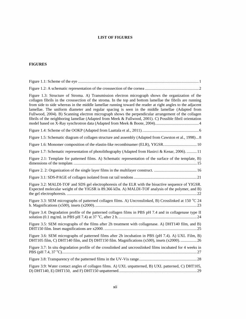
Figure 1.1: Scheme of the eye ....................................................................................................................... 1
Figure 1.2: A schematic representation of the crosssection of the cornea ..................................................... 2
Figure 1.3: Structure of Stroma. A) Transmission electron micrograph shows the organization of the
collagen fibrils in the crosssection of the stroma. In the top and bottom lamellae the fibrils are running
from side to side whereas in the middle lamellae running toward the reader at right angles to the adjacent
lamellae. The uniform diameter and regular spacing is seen in the middle lamellae (Adapted from
Fullwood, 2004). B) Scanning electron micrograph shows the perpendicular arrangement of the collagen
fibrils of the neighboring lamellae (Adapted from Meek & Fullwood, 2001). C) Possible fibril orientation
model based on X-Ray synchrotron data (Adapted from Meek & Boote, 2004). .......................................... 4
Figure 1.4: Scheme of the OOKP (Adapted from Laattala et al., 2011). ....................................................... 6
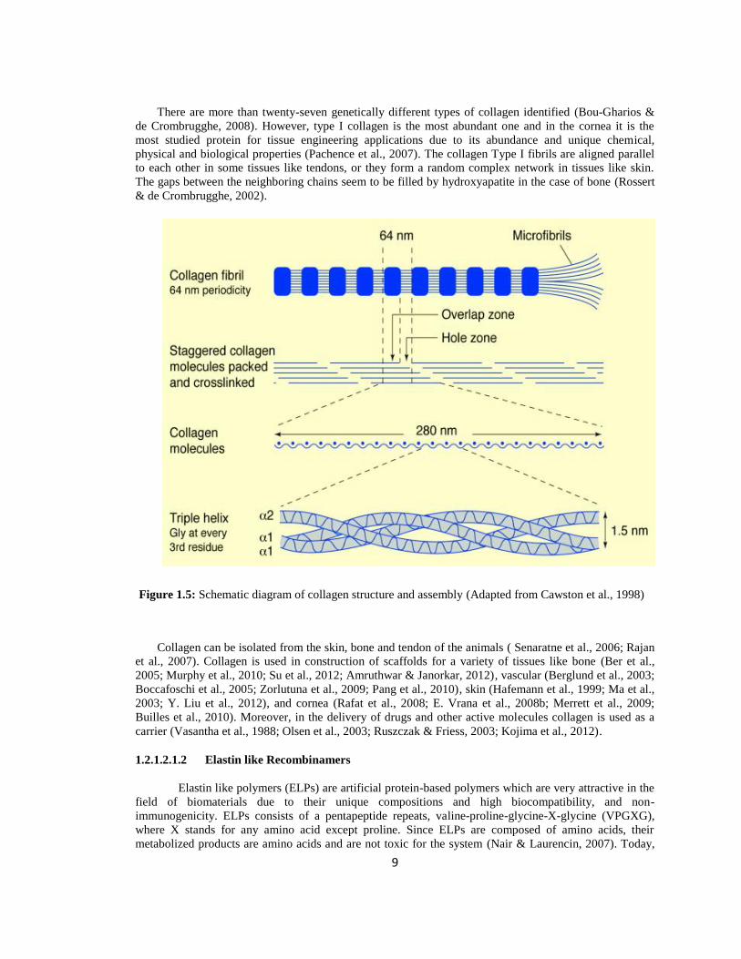
Figure 1.5: Schematic diagram of collagen structure and assembly (Adapted from Cawston et al., 1998) ... 8
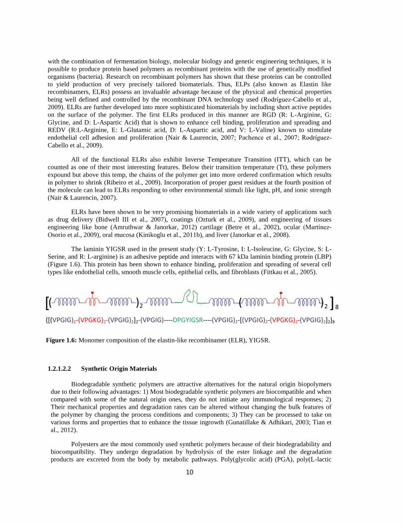
Figure 1.6: Monomer composition of the elastin-like recombinamer (ELR), YIGSR. ................................ 10
Figure 1.7: Schematic representation of photolithography (Adapted from Hasirci & Kenar, 2006). .......... 11
Figure 2.1: Template for patterned films. A) Schematic representation of the surface of the template, B)
dimensions of the template. ......................................................................................................................... 15
Figure 2. 2: Organization of the single layer films in the multilayer construct. .......................................... 16
Figure 3.1: SDS-PAGE of collagen isolated from rat tail tendons .............................................................. 21
Figure 3.2: MALDI-TOF and SDS gel electrophoresis of the ELR with the bioactive sequence of YIGSR.
Expected molecular weight of the YIGSR is 89.366 kDa. A) MALDI-TOF analysis of the polymer, and B)
the gel electrophoresis. ................................................................................................................................ 22
Figure 3.3: SEM micrographs of patterned collagen films. A) Uncrosslinked, B) Crosslinked at 150 oC 24
h. Magnifications (x500), insets (x2000). .................................................................................................... 23
Figure 3.4: Degradation profile of the patterned collagen films in PBS pH 7.4 and in collagenase type II
solution (0.1 mg/mL in PBS pH 7.4) at 37 oC, after 2 h. ............................................................................. 24
Figure 3.5: SEM micrographs of the films after 2h treatment with collagenase. A) DHT140 film, and B)
DHT150 film. Inset magnifications are x2000. ........................................................................................... 25
Figure 3.6: SEM micrographs of patterned films after 2h incubation in PBS (pH 7.4). A) UXL Film, B)
DHT105 film, C) DHT140 film, and D) DHT150 film. Magnifications (x500), insets (x2000). ................ 26
Figure 3.7: In situ degradation profile of the crosslinked and uncrosslinked films incubated for 4 weeks in
PBS (pH 7.4, 37 oC). .................................................................................................................................... 27
Figure 3.8: Transparency of the patterned films in the UV-Vis range. ........................................................ 28
Figure 3.9: Water contact angles of collagen films. A) UXL unpatterned, B) UXL patterned, C) DHT105,
D) DHT140, E) DHT150, and F) DHT150 unpatterned. ............................................................................ 29

xiii
Figure 3.10: Scheme of the water droplet on the patterned surface. A) Immediate, B) after 5 min, and C)
after total filling of the patterns. ................................................................................................................... 30
Figure 3.11: SEM micrograph of uncrosslinked Col:ELR films. Magnifications (x50), insets (x150). ...... 31
Figure 3.12: Degradation profile of patterned Col and Col:ELR films in collagenase type II solution (0.1
mg/mL in PBS, pH 7.4) at 37 oC, after 2 h. ................................................................................................. 32
Figure 3.13: Insitu degradation profile of the patterned films incubated for 4 weeks in PBS (pH 7.4, 37 oC). ............................................................................................................................................................... 33
Figure 3.14: Transparency of the patterned Col and Col:ELR films in the UV-Vis range .......................... 34
Figure 3.15: Transparency of the single layer films is shown by stereomicrographs. A) UXL Col, B)
DHT150 Col, C) UXL Col:ELR, D) DHT150 Col:ELR. Magnifications (x3), insets (x8). ........................ 35
Figure 3.16: Water contact angles. A) UXL Col, B) DHT150 Col, C) UXL Col:ELR, and D) DHT150
Col:ELR. ...................................................................................................................................................... 36
Figure 3.17: Stereomicrograph of multilayer scaffold with 4 layers of UXL Col film. Magnification: x45.
..................................................................................................................................................................... 38
Figure 3.18: Stereomicrographs of the films for transparency. A) Single layer UXL Col film, B) multilayer
UXL Col scaffold, C) multilayer DHT150 Col scaffold, and D) Multilayer Col:ELR scaffold.
Magnifications (x3), insets (x8) ................................................................................................................... 39
Figure 3.19: Proliferation of keratocytes on Col and Col:ELR films in 3 weeks. (Initial cell seeding density
per sample: 4x10⁴) ....................................................................................................................................... 40
Figure 3.20: SEM micrograph of patterned collagen film. Arrow shows the unpatterned region.
Magnification (x100). .................................................................................................................................. 41
Figure 3.21: Fluorescence micrographs of DAPI stained human keratocytes on patterned Col films. Time
of incubation (days): A, B) 1, C, D) 7, and E, F) 21. Scale bars: 50 µm. ................................................... 42
Figure 3.22: Fluorescence micrographs of DAPI stained human keratocytes on unpatterned Col films.
Time of incubation (days): A, B) 1, C, D) 7, and E, F) 21. Scale bars: 50 µm. ........................................... 43
Figure 3.23: Fluorescence micrographs of DAPI stained human keratocytes on patterned Col:ELR films on
the 14th day. Scale bars: A) 200 µm, B) 100 µm. ........................................................................................ 44
Figure 3.24: Fluorescence micrographs of human corneal keratocytes on collagen films stained with
phalloidin-FITC after 14 days of incubation. A) Unpatterned Col film, B) patterned Col film. Scale bars:
50 µm. .......................................................................................................................................................... 44
Figure 3.25: Behavior of human corneal keratocytes. A-C) Fluorescence micrograph of human corneal
keratocytes on unpatterned Col films stained with phalloidin-FITC on day 14. Scale bar is: A) 100 µm, B,
C) 20 µm. D) Phase contrast image of human corneal keratocytes on transwell membrane after 1 week.
Scale bar: 20 µm (Adapted from Guo et al., 2007). ..................................................................................... 45
Figure 3.26: Fluorescence micrograph of human corneal keratocytes on Col:ELR films stained with
phalloidin FITC after 14 days of incubation. Scale bars are: A) 50 µm, B) 20 µm. .................................... 46
Figure 3.27: SEM micrographs of human corneal keratocytes on unpatterned Col films. Time of
incubation (days): A, B) 1, and C, D) 7. Magnifications A, C) x50, and B, D) x200. ................................ 47
Figure 3.28: SEM micrographs of human corneal keratocytes on patterned Col films. Time of incubation
(days): A, B) 1, and C, D) 7. Magnifications: A, C) x50, and B, D) x100. ................................................. 48
Figure 3.29: Transparency of the Col and Col:ELR films. Days A) 1, B) 20, and C) 30. Transparency of
the films was compared with transparency of native cornea (Meek et al., 2003). ....................................... 50
Figure 3.30: Improvement of transparency over 30 days at 700 nm. A) Col films, and B) Col:ELR films. 51
xiv
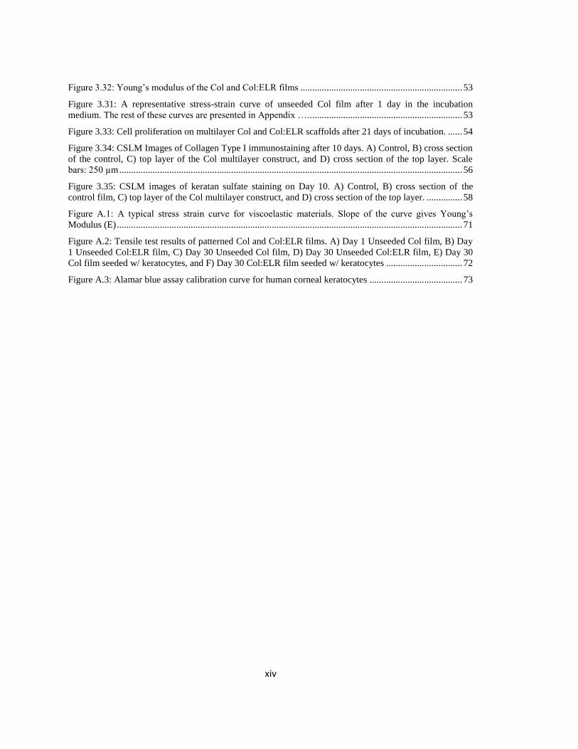
Figure 3.32: Young’s modulus of the Col and Col:ELR films .................................................................... 53
Figure 3.31: A representative stress-strain curve of unseeded Col film after 1 day in the incubation
medium. The rest of these curves are presented in Appendix …. ................................................................ 53
Figure 3.33: Cell proliferation on multilayer Col and Col:ELR scaffolds after 21 days of incubation. ...... 54
Figure 3.34: CSLM Images of Collagen Type I immunostaining after 10 days. A) Control, B) cross section
of the control, C) top layer of the Col multilayer construct, and D) cross section of the top layer. Scale
bars: 250 µm ................................................................................................................................................ 56
Figure 3.35: CSLM images of keratan sulfate staining on Day 10. A) Control, B) cross section of the
control film, C) top layer of the Col multilayer construct, and D) cross section of the top layer. ............... 58
Figure A.1: A typical stress strain curve for viscoelastic materials. Slope of the curve gives Young’s
Modulus (E) ................................................................................................................................................. 71
Figure A.2: Tensile test results of patterned Col and Col:ELR films. A) Day 1 Unseeded Col film, B) Day
1 Unseeded Col:ELR film, C) Day 30 Unseeded Col film, D) Day 30 Unseeded Col:ELR film, E) Day 30
Col film seeded w/ keratocytes, and F) Day 30 Col:ELR film seeded w/ keratocytes ................................ 72
Figure A.3: Alamar blue assay calibration curve for human corneal keratocytes ....................................... 73
xv
LIST OF TABLES
TABLES
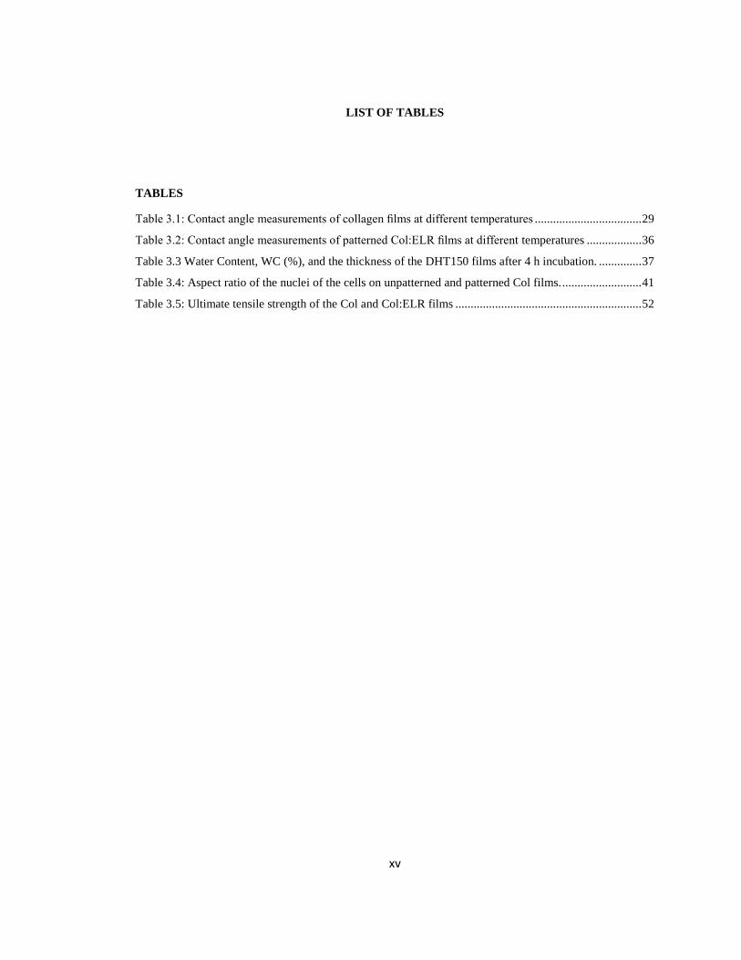
Table 3.1: Contact angle measurements of collagen films at different temperatures ................................... 29
Table 3.2: Contact angle measurements of patterned Col:ELR films at different temperatures .................. 36
Table 3.3 Water Content, WC (%), and the thickness of the DHT150 films after 4 h incubation. .............. 37
Table 3.4: Aspect ratio of the nuclei of the cells on unpatterned and patterned Col films. .......................... 41
Table 3.5: Ultimate tensile strength of the Col and Col:ELR films ............................................................. 52
xvi
LIST OF ABBREVIATIONS
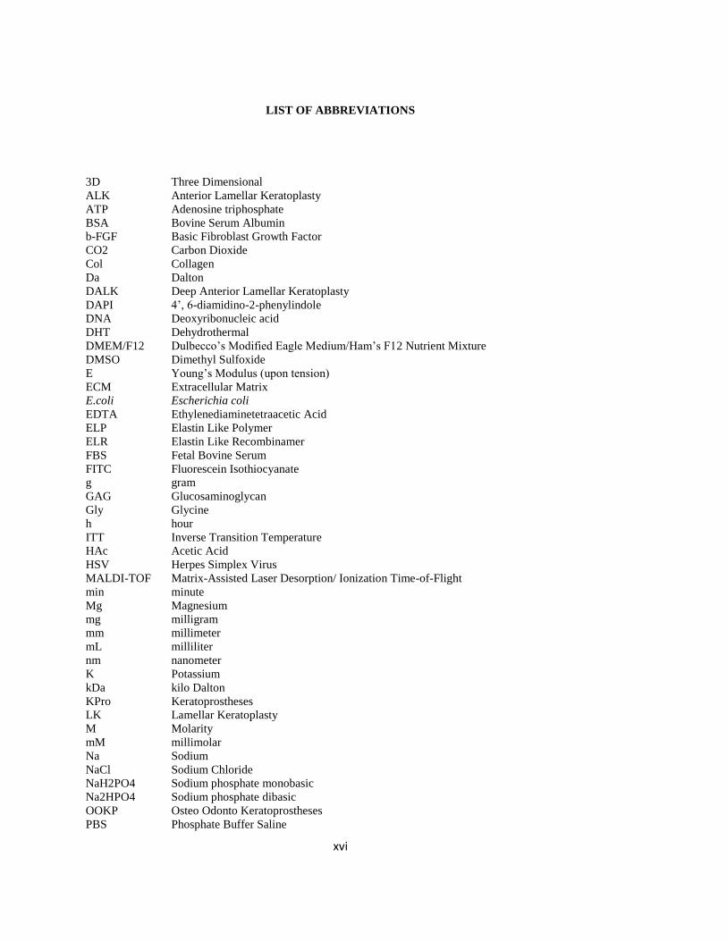
3D Three Dimensional
ALK Anterior Lamellar Keratoplasty
ATP Adenosine triphosphate
BSA Bovine Serum Albumin
b-FGF Basic Fibroblast Growth Factor
CO2 Carbon Dioxide
Col Collagen
Da Dalton
DALK Deep Anterior Lamellar Keratoplasty
DAPI 4’, 6-diamidino-2-phenylindole
DNA Deoxyribonucleic acid
DHT Dehydrothermal
DMEM/F12 Dulbecco’s Modified Eagle Medium/Ham’s F12 Nutrient Mixture
DMSO Dimethyl Sulfoxide
E Young’s Modulus (upon tension)
ECM Extracellular Matrix
E.coli Escherichia coli
EDTA Ethylenediaminetetraacetic Acid
ELP Elastin Like Polymer
ELR Elastin Like Recombinamer
FBS Fetal Bovine Serum
FITC Fluorescein Isothiocyanate
g gram
GAG Glucosaminoglycan
Gly Glycine
h hour
ITT Inverse Transition Temperature
HAc Acetic Acid
HSV Herpes Simplex Virus
MALDI-TOF Matrix-Assisted Laser Desorption/ Ionization Time-of-Flight
min minute
Mg Magnesium
mg milligram
mm millimeter
mL milliliter
nm nanometer
K Potassium
kDa kilo Dalton
KPro Keratoprostheses
LK Lamellar Keratoplasty
M Molarity
mM millimolar
Na Sodium
NaCl Sodium Chloride
NaH2PO4 Sodium phosphate monobasic
Na2HPO4 Sodium phosphate dibasic
OOKP Osteo Odonto Keratoprostheses
PBS Phosphate Buffer Saline

xvii
PCL Poly(ε-caprolactone)
PDMS Poly(dimethylsiloxane)
PEG Polyethylene Glycol
PE Polyethylene
Pen/Strep Penicillin/Streptomycin
PGA Poly(glycolic acid)
PHB Poly(3-hydroxybutyrate)
PHBV Poly(3-hydroxybutyrate-co-3-hydroxyvalerate)
PHEMA Poly(2-hydroxyethyl methacrylate)
PK Penetrating Keratoplasty
PLA Poly(lactic acid)
PLGA Poly(Lactic Acid-co-Glycolic Acid)
PLLA Poly(L-Lactic Acid)
PMMA Poly(methyl methacrylate)
S(%) Swelling Ratio
SALK Superficial Anterior Lamellar Keratoplasty
SDS-PAGE Sodium Dodecyl Sulphate- Polyacrylamide Gel Electrophoresis
SEM Scanning Electron Microscopy
TCPS Tissue Culture Polystyrene
Tt Transition Temperature
UTS Ultimate Tensile Strength
UV Ultra Violet
UXL Uncrosslinked
v/v volume/volume
WHO World Health Organization
w/v weight/volume
µm micrometer


1
CHAPTER 1
INTRODUCTION
1.1 Cornea
The cornea is the most exterior, transparent surface of the eye which is roughly 500 µm thick in
the center and the diameter is about 12 mm (Figure 1.1) (Z. Liu et al., 1999). There are two main functions
of the cornea: (1) to protect the eye by serving as a barrier against external objects by virtue of its
position. (2) To function as the principal optical element of the eye by refracting 70% of the light incom-
ing into the eye (Buerman & Pedroza, 1996; Trinkaus-Randall, 2000; McLaughlin et al., 2009). Cornea is
one of the avascular tissues in the body, a property essential for its transparency. Oxygen and glucose
needed to maintain the normal metabolic functions of the cornea is supplied by diffusion from the tear film
that forms on its external surface and the aqueous humor on the inside, respectively (Nishida, 2005).
1.1.1 Structure of the Cornea
Cornea has a layered structure composed of the Epithelium at the surface, Bowman’s layer, Stroma,
Descemet’s membrane and Endothelium (Figure 1.2).
Corneal epithelium is 50-90 µm thick and forms the exterior layer of the cornea. Five-six layers of
epithelial cells in the form of stratified, squamous and non-keratinized layers. Due to the strong junctions
between the adjacent cells, the epithelium functions as a barrier against the microorganisms, and other
Figure 1.1: Scheme of the eye

2
extraneous bodies. However, it is permeable to several molecules needed by the eye including CO2, O2,
glucose, and sodium (Kaji, 2002).
Randomly arranged type I, III and IV collagen fibers and proteoglycans form the 12 µm Bowman’s
layer which is beneath the epithelium layer. Since the collagen fibers are formed by the secretion of
stromal keratocytes, it is considered as the anterior part of the stroma and its physiological function still
remains unclear (Kaji, 2002; Nishida, 2005).
90% of the cornea is constituted by the stroma which is around 400 µm in thickness and it plays a
major role in the protection, transmission and refraction by the cornea (Ruberti et al., 2007). Stroma is
composed of mainly Type I collagen (70%) and glycosaminoglycans (GAGs), keratan sulfates (lumican,
mimecan, and keratocan), and proteoglycans are the other extracellular matrix (ECM) components that
make up the stroma (McLaughlin et al., 2009; Torbet et al., 2007). 3-10 % of the stroma (by volume) is
composed of the stromal fibroblasts called keratocytes (Torbet et al., 2007).
Beneath the stroma, there is a 12 µm thick basement membrane named Descemet’s membrane.
Laminin and Type IV collagen are the main proteins of this layer (Kaji, 2002; Asbell & Brocks, 2011).
Endothelium is the innermost layer of the cornea and it is composed from 400,000 hexagonal cells.
This layer is important for the maintenance of transparency of the cornea and the hydration of the stroma.
Corneal hydration is controlled via a fluid pump mechanism driven by Na+, K
+ ATPase in the endothelium
(Ruberti et al., 2007; McLaughlin et al., 2009)
1.1.1.1 Cells of the Cornea
Cornea is composed of three different cell types, namely epithelial cells, keratocytes and endothe-
lial cells.
The epithelium consists of a multilayered (five to seven layers) stratified squamous epithelium which
has a continual turn over capability (every five to seven days) due to stem cells located at the corneal
limbus. The limbus is situated in a transitional zone between the cornea and the conjunctiva. The stem
Figure 1.2: A schematic representation of the crosssection of the cornea
3
cells at the limbus are vital for the repair and regeneration of the corneal epithelium. There are three layers
that form corneal epithelium; basal cell layer (next to the basement membrane), wing cell layers, and
superficial cell layers. Among these layers, only the cells at the basal layer undergo mitosis. The cells
derived from basal cells differentiate into wing and superficial cells. Superficial cell layer provides a
protective barrier for the cornea (Suzuki et al., 2003; Vacanti & Vacanti, 2007).
Stromal keratocytes are mesenchyme-derived cells distributed throughout the collagen-proteoglycan
matrix (3-10%, v/v) of the stroma. They play a major role in the maintenance of transparency of the cornea
both by expression of crystalline proteins and also by preserving the organization of the stroma by
producing proteoglycans continuously (Ruberti et al., 2007). Any cell loss or phenotype change in the
stroma leads to a dramatic decrease in corneal transparency (Jester et al., 1999). Upon injury, the cells are
stimulated either to go through apoptosis or to change phenotype to the repair phenotypes. In the case of
apoptosis (observed when the epithelium layer is scraped away) the keratocytes beneath the epithelium
undergo cell death and they are replaced with a new keratocyte population after a short time by mitosis of
the neighboring cells. This response is thought to protect the cornea from further inflammation and loss of
clarity (West-Mays & Dwivedi, 2006). In pathological corneas, during wound-healing process, keratocytes
change their normal quiescent phenotypes into fibroblast and myofibroblasts and this change is character-
ized by reduced transparency due to a fibrotic extracellular matrix accumulation which is different from
normal glycosaminoglycans of the stroma. Normal quiescent keratocytes express protein and mRNA for
keratocan, aldehyde dehydrogenase class 3 and secrete keratan sulfate. On the other hand, repair transition
is characterized by a high level of α-smooth muscle actin expression and the fibroblasts in the region start
to repair the injury site by the secretion of biglycan, fibronectin, and collagen Type I and Type III
(Funderburgh et al., 2003). Finally, this fibroblastic conversion is associated with the loss of transparency
due to a decrease in expression of crystallins such as transketolase (TKT) (Jester et al., 1999; Mu-
thusubramaniam et al., 2012). Following tissue repair, fibroblasts gradually gain keratocyte phenotype by
becoming quiescent and transparent (Fini, 1999).
Corneal endothelium is composed of monolayer squamous endothelial monolayer that constitutes a
barrier between the anterior chamber and the stroma. The main function of this layer is to maintain
transparency by keeping cornea hydrated. It prevents corneal stroma from swelling by eliminating the
excess fluid with the activity of Na+/K
+ pumps and Mg
+ ionic pumps. Endothelium layer also provides
nutrient to the avascular cornea by permitting the nutrients to go through. Thus, the barrier and pump
functions of the endothelium are essential for the maintenance of the transparency, dehydrated state and
the thickness of the cornea (Joyce, 2003; Bourne & McLaren, 2004; Teichmann et al., 2013).
1.1.1.2 Structure and Components of Stroma
The stroma is approximately 400 µm in thickness, containing 200-400 lamellae with 31 nm of
uniform diameter and regular spacing to each other (Meek & Leonard, 1993). The lamellae forming the
corneal stroma are parallel to the corneal surface and at right angles to adjacent lamellae forming a
plywood-like structure (Figure 1.3 A, B). This organization of the fibrils is essential for both the biome-
chanical and the optical properties of the cornea (Meek, 2009). Mechanical properties are very important
for the maintenance of normal functions of the cornea. The cornea must not be ruptured with traumatic
impacts and withstand the tensile stress imposed by the intraocular pressure (IOP). This load bearing
property is a result of the complex organization of the stromal tissue (Figure 1.3 B, C) (Ethier et al., 2004;
Ruberti & Zieske, 2008). Corneal transparency is achieved mainly by the chemistry and the organization
of the extracellular matrix (ECM) and by the stromal cells, keratocytes. Collagen Type I and Type V
fibrils are the major constituents of the stroma and transparency is attributed to uniform fibril diameter,
direction, and packing (Maurice, 1957; Meek & Fullwood, 2001). Proteoglycans are the second major
group of molecules forming the stroma. Decorin contains chondroitin and dermatan sulfate and lumican,
mimecan and keratocan contain keratan sulfate. Experiments with knock-out mice showed that keratocan
deficient mice displayed cloudy corneas when mature. Cloudy corneas were also developed in the lumican
deficient ones due to abnormal fibril diameter. This implies that lumican is an important GAG for the
stromal collagen organization and together with other proteoglycans they are important for the clarity of
the stroma and the cornea (Chakravarti et al., 2000; Meek & Boote, 2004).

4
A B C
Figure 1.3: Structure of Stroma. A) Transmission electron micrograph shows the organization of the collagen
fibrils in the crosssection of the stroma. In the top and bottom lamellae the fibrils are running from side to
side whereas in the middle lamellae running toward the reader at right angles to the adjacent lamellae. The
uniform diameter and regular spacing is seen in the middle lamellae (Adapted from Fullwood, 2004). B)
Scanning electron micrograph shows the perpendicular arrangement of the collagen fibrils of the neighboring
lamellae (Adapted from Meek & Fullwood, 2001). C) Possible fibril orientation model based on X-Ray
synchrotron data (Adapted from Meek & Boote, 2004).
1.1.2 Corneal Diseases
Corneal diseases and wounds are the second major cause of blindness after cataract and are esti-
mated to affect 27.9 million people worldwide of which 4.9 million with bilateral corneal blindness (Oliva
et al., 2012). The major causes of corneal blindness are trachoma, ocular trauma and corneal ulcerations
and childhood blindness.
Trachoma is a chronic and the most common infectious disease worldwide and it is estimated by
World Health Organization (WHO) that 12 million people will develop trachoma related blindness by
2020. Thus, trachoma is placed in the intervention priority list of WHO. Trachoma is a result of repeated
reinfection by an intracellular bacterium Chlamydia trachomatis and leads blindness 10- 40 years after
infection (Dean et al., 2008). Chronic inflammation because of repeated infections results in the scarring
of conjunctiva, in-turning of eyelashes (trichiasis) resulting from upper lid shortening and abrading of the
cornea. Finally scarring, corneal opacity, and blindness are seen if the disease progresses and the cornea is
not treated. Trachoma is found among poor populations and spread from eye to eye by close contact.
WHO aims to prevent trachoma related blindness with the SAFE strategy; Surgery for trichiasis, Antibi-
otic treatment, Facial cleanliness, Environmental changes and improvements (Oliva et al., 2012).
Trauma is a major problem worldwide which causes unilateral visual impairment and corneal
blindness due to severe eye injuries. There are 1.6 million blind people because of injuries and additional
19 million people suffer unilateral blindness or low vision and 2.3 million people are with bilateral low
vision. Accidents are the most common causes of ocular traumas which are followed by sports activities,
burns, traffic accidents, foreign bodies, and firearm accidents (Strahlman et al., 1990; Negrel & Thylefors,
1998).
Ulceration of cornea is another major sight-threatening problem. In this case, the epithelium is
damaged and in severe cases stroma inflammation is seen. Loss of stromal tissue due to inflammation
results in stromal lysis (Coster, 2002b). Ulceration can be a result of either external influences like
physical trauma, heat or infection, exposure to chemicals or intrinsic influences like dystrophies and stem
cell deficiency. The cornea can be destroyed in 24 h if the infected ulcer is not treated (Coster, 2002a).

5
The reasons of the childhood blindness vary between regions and by socioeconomic positions in
that society. While high income countries are facing retinopathy due to prematurity, optic nerve hypo-
plasia, and cortical visual impairment, the causes in the low income countries are generally corneal
scarring from measles, vitamin A deficiency, use of traditional eye remedies, and infectious keratitis and
ophthalmia neonatorum (Isenberg et al., 2009). In general, the causes of childhood blindness can be
classified as: genetic and chromosomal abnormalities, intra-uterine period problems like infections and
toxins, causes that emerged at the time of birth or in the post-natal period like cerebral hypoxia, retinopa-
thy, and ophthalmia neonatorum, and factors which are influential in the childhood such as vitamin A
deficiency and trauma (Foster & Gilbert, 1992). In addition to these causes, herpes simplex virus (HSV)
infections, keratoconjunctivitis and chemical keratitis are other potential sources of risk for childhood
blindness (Whitcher et al., 2001).
1.1.2.1 Approaches for the Treatment of Corneal Damages
Cornea transplantation, penetrating keratoplasty (PK) is the most widely used treatment world-
wide for permanently opacified, scarred or severely deformed corneas that clear vision cannot be achieved
by spectacles or contact lenses. PK refers to full-thickness corneal replacement and among other organ
transplantations it has the highest success rate (90%). However the success rate decreases dramatically in
complex cases if the cornea develops edema or glaucoma, or if the cornea is highly vascularized and
scarred. Cases with severe chemical burns, trachoma, dry eye syndrome, Stevens-Johnson syndrome, and
vascularized corneas due to injury are also in the low success risk group for transplantation (Chirila et al.,
1998).
In less complex cases where only some parts of the cornea are affected like in various corneal
dystrophies, and keratoconus, lamellar keratoplasty (LK) is used instead of PK. In the case of Anterior
lamellar keratoplasty (ALK), stroma, endothelium and Descemet’s membrane are left intact while the
diseased epithelium layer is removed. Superficial anterior lamellar keratoplasty (SALK) is used if the 30-
40 % of the cornea is damaged and the diseased tissue is replaced with the same amount of healthy donor
tissue. On the other hand, deep anterior lamellar keratoplasty (DALK) includes removal of diseased
stroma and Descemet’s membrane while leaving endothelium layer intact (Al-Kharashi et al., 2009).
Anterior lamellar keratoplasty surgeries are more advantageous than PK surgeries where sutures are
removed earlier and also the visual recovery occurs faster than normal PK procedures (Arenas et al.,
2012).
Although success rate is very high in corneal transplantation when compared to other solid or-
gans, and graft rejection is prevented extensively by topical steroids and immune-suppressive drugs, graft
failure is still a serious problem (Panda et al., 2007). Shortage of donor tissue is major problem in corneal
transplantation which leaves millions of patients untreated. The available corneal tissues decrease in
number with the corneal surgeries like in situ keratomileusis (LASIK), infectious diseases like HIV and
hepatitis, and with increasing age (Chirila, 2001; Muraine et al., 2002).
Keratoprostheses are the artificial corneas that are the only other choice for patients with several
corneal graft rejection histories. Standard PK procedure is used to replace the damaged tissue with this
artificial cornea to repair the function of the cornea. The first attempts to make an artificial cornea were
made in the 19th
century by De Quengsy with the first glass implantation to the rabbits (Chirila et al.,
1998). However, unsuccessful results with glass samples due to high risk of removal of the material from
the cornea lead to the use of synthetic polymers. Poly(methyl methacrylate) (PMMA) was the first
polymer that was used as a keratoprosthetic material, and this attempt was followed by the use of other
synthetic polymers. With the concept of “core-and-skirt” model where the porous skirt surrounds the
central core material of the prostheses, it was aimed to obtain a good integration of the material with the
host tissue. Today, most of the keratoprostheses designs are based on this model where the elastic, porous
skirt allows ingrowth of the fibroblasts for anchorage of the cornea (Chirila et al., 1998; Griffith et al.,
2009; Myung et al., 2008). However, due to problems like calcification, infection, and retinal detachment,
keratoprostheses are used as an alternative to transplantation when the grafts fail repetitively (Griffith et
al., 2011). Osteo-odonto keratoprosthesis (OOKP), Boston KPro, and AlphaCorKPro are three most
commonly used types of keratoprostheses.

6
Osteo-odonto keratoprostheses (OOKP) was developed by Strampelli in 1963 where the mucous
membrane covers the PMMA cylinder (Figure 1.4). Although OOKP ensures a good control over the
immunological complications the surgical procedure is very complex and time consuming. Extrusion,
glaucoma, retinal detachment and retroprosthetic membrane formation are the major problems associated
with OOKP (C. Liu et al., 2005; Viitala et al., 2009).
The Boston KPro uses a collar-button design where PMMA is used to form the front plate for car-
rying optical stem and back plate with holes to allow hydration and nourishment of the cornea. Titanium
ring is used to lock the device to the donor corneal graft and then the device is sutured to the host (Robert
& Harissi-Dagher, 2011). Although antibiotics like Vancomycin are extensively reduced the severe
complications such as necrosis and endophthalmitis, glaucoma still remains a problem for Boston KPro
patients (Güell et al., 2011).
The AlphaCorKPro, also known as Chirila keratoprosthesis, is made from crosslinked poly(2-
hydroxyethyl methacrylate) (PHEMA) gel forming the central optic and the sponge skirt. With this design
it was aimed to lower the mechanical stress, prevent leakage, and downgrowth of epithelium which are
common problems with other designs. However, fibrous closure, white intraoptic deposits, and low sight
due to complications are the reported problems associated with AlphaCor device (Gomaa et al., 2010;
Hicks et al., 2006).
1.2 Tissue Engineering
The field of tissue engineering was originated from the biomaterials sciences in the last few dec-
ades and aims to replace, restore or improve the function of the tissues in the case of diseases or injuries
by using cells, extracellular matrix components or biomaterials (Langer & Vacanti, 1993). Tissue engi-
neering involves obtaining cells from the host’s tissues and proliferating them on appropriate 3
dimensional tissue substitutes or scaffolds, which mimic the natural structure, composition and function of
the tissue. The scaffolds play a significant role in supporting cell attachment, proliferation, and extracellu-
lar matrix (ECM) production by providing a framework. An ideal scaffold should mimic the natural
human tissue by its micro and macrostructure (C. Liu et al., 2007). The scaffold should degrade in time
Figure 1.4: Scheme of the OOKP (Adapted from Laattala et al., 2011).

7
while the newly formed tissue takes its place. In the future, by tissue engineering it is aimed to reduce and
eventually eliminate the need for organ transplants and problems associated with transplantation like
limited number of donated organs and risk of disease transmission (L. G. Griffith & Naughton, 2002)
1.2.1 Corneal Tissue Engineering
1.2.1.1 Cells and Sources Used in Corneal Tissue Engineering
The cells used in corneal tissue engineering are specific to the targeted layer. Cells are obtained in
two different ways: direct isolation from the tissue of the host (patient or the animal) or using stem cells
that have the ability to differentiate into the desired cell type (Vacanti & Vacanti, 2007).
The epithelium cells used in tissue engineering purposes can be the cells at the basal layer or stem
cells at the limbus and can be isolated by enzymatic digestion. The cells at the central cornea have
proliferation capability only for two or three passages. On the other hand, the stem cells at the limbus have
a higher proliferation potential (seven passages) and they grow much better in the culture compared to the
central cornea cells (Germain et al., 2000). Stem cells isolated from other tissues like oral mucosal cells
and bone marrow stem cells can also be used as an alternative to limbus stem cells (Chen et al., 2009;
Jiang et al., 2010).
Keratocytes can be isolated from the corneal stroma after removing the epithelial layer and digest-
ing the sample with dispase. Another option for isolation of the stromal cells is the obtaining them from
keratocyte contaminant epithelium cell culture by changing the medium into a keratocyte culture medium.
After several subculturing, the epithelial cells are lost due to inappropriate medium for them to proliferate
(Germain et al., 2000).
The isolation of endothelial cells was a challenge earlier due to strong adherence of the cells to the
Descemet’s membrane and the common trypsin treatment damages cells that leads to degradation of the
cells because of longer incubation times. Instead of usual trypsin treatment, collagenase type IV treatment
works well and high numbers of free endothelial cells can be obtained. Another problem with the isolation
of endothelial cells is the contamination of the culture with stromal cells which is solved by using a
selective medium appropriate for endothelial cells that contains D-valine instead of L-valine (Engelmann
et al., 1988; Engelmann et al., 2004).
Cornea seems to be an attractive tissue for tissue engineering to due to its simple, avascular and
multilaminar structure. However, those three different cell types mentioned above need to be successfully
cultured if a functional corneal equivalent is desired to be constructed (Ruberti et al., 2007). Although
there are several studies attempted to construct tissue engineered cornea with three layers (McLaughlin et
al., 2010; Vrana et al., 2008b), most of the studies focused on reconstructing one (Torbet et al., 2007;
Wang et al., 2009) or two layers of the cornea ( Zorlutuna et al., 2006; Builles et al., 2010).
1.2.1.2 Scaffolds Used in Corneal Tissue Engineering
1.2.1.2.1 Natural Origin Materials
Natural origin materials are widely employed in tissue engineering applications due to their various
characteristics like biocompatibility, biodegradability, gelation ability, and water binding capacity.
Additionally, they can be modified or conjugated with other molecules via chemical or enzymatic
reactions. Natural polymers are hydrolyzed or degraded by the enzymes and metabolized by the biological
systems (Sawhney & Drumheller, 1998). They also possess some disadvantages; induction of immune
responses, variability with the source, batch-to-batch variability and limited sources. With the new
processes and techniques of purification and production, these materials are being developed into better
materials for tissue engineering (Correlo et al., 2011). Among the extremely broad range of polymers,
three major classes of them are more widely used in tissue engineering than others; polyhydroxyalka-
8
noates, polysaccharidic polymers and protein-origin polymers. These polymers are obtained from plant,
animal or algae sources and also microorganisms are employed to produce them via fermentation or
enzymatic reactions (Hasırcı et al., 2001).
Polyhydroxyalkanoates are degradable and biocompatible and form a large family of polymers and
the main molecules used in tissue engineering are mainly 3-hydroxybtyric acid (PHB) and copolymers of
PHB with hydroxyalkanoates like 3-hydroxyvaleric acid (PHBV) (Hasırcı et al., 2001). They are promis-
ing polymers for biomedical field because of their mechanical strengths, biodegradability, and capability
of fiber formation. For example, micropatterned films from PHBV have been used in the engineering of
tissues like cornea (Zorlutuna et al., 2006; Zorlutuna et al., 2007), cartilage (Köse et al., 2005), bone (
Köse et al., 2003; Kenar et al., 2006), cardiac (Kenar et al., 2011), and nerve (Yucel et al., 2010).
Polysaccharides are also used in cornea tissue engineering applications due to their biocompatibil-
ity, low cost in production, and non-toxicity. They can be obtained from a variety of sources such as
microorganisms, animals and plants. Their chemical and physical properties vary according to their
molecular weight and composition (Nair & Laurencin, 2007). Chondroitin sulfate is one of the polysac-
charides used in the construction of foams together with collagen in cornea engineering and the scaffold
was successfully populated with three cell types of the cornea (Vrana et al., 2008b). Rafat et al. (2008)
used a chitosan-collagen blend in the construction of scaffolds for corneal epithelium. Their results
showed that these scaffolds are biocompatible, elastic, optically clear and mechanically strong. Hyaluronic
acid is another polysaccharide used in cornea reconstructs. Films consisting of collagen-gelatin-hyaluronic
acid have been used and were shown to have appropriate hydrophilicity, mechanical strength and optical
clarity. Additionally, corneal epithelial cells populated the scaffolds well which shows the suitability of
this scaffold (Y. Liu et al., 2013).
Proteins are the major component of the extracellular matrices and they contribute to tissue regen-
eration, wound healing, and regulation pathways. Proteins are used for constructing sutures, scaffolds, and
drug delivery systems. They degrade by hydrolysis via the enzymes of the host organism (Nair & Lau-
rencin, 2007). Proteins produced by recombinant DNA technology avoid batch to batch variations risk of
naturally occurring proteins by making the production of proteins with defined properties possible (Girotti
et al., 2004). Collagen is thought to be an ideal scaffold material for corneal tissue engineering since it is
the major component of the stroma. It has been shown that micropatterned, crosslinked collagen films
helped alignment of human corneal keratocytes and improved the mechanical strength and the transparen-
cy of the scaffold (Vrana et al., 2008a; Vrana et al., 2007b). In another study, crosslinked collagen foams
were shown to be populated well with the stromal cells (Vrana et al., 2007a). Silk fibroin is another
protein used extensively in cornea engineering. RGD-functionalized silk protein constructs have been
shown to replicate the normal lamellar structure of the corneal stroma and remain transparent. The
scaffolds supported cell attachment, proliferation and alignment (Gil et al., 2010). Since collagen and
elastin like recombinamers are used in the present study, they will be explained in more detail in the
following section.
1.2.1.2.1.1 Collagen
Collagen is the major constituent of the mammalian tissues like cornea, skin, bone, cartilage and
blood vessels. It has an important role in the attachment, regulation of proliferation, differentiation,
anchorage, and survival of the cells (Wess, 2005). Three polypeptide chains constitute the motif of triple
helix of the collagen with the repeating amino acid sequences Gly-X-Y. This repeating structure provides
coiling to a left handed motif to each procollagen, and assembly into a right handed helix of the three
chains to form triple-helix. After the secretion, the globular ends of the procollagen chains are cleaved
leaving the collagen. Individual collagen molecules align parallel to each other to form fibril structure with
a 64 nm gap (Cawston, 1998). The center of the triple helix is settled by Gly residues and the surface of
the helix is situated by X and a Y residue where X is usually proline and Y is hydroxyproline. Hydroxy-
proline is an important amino acid for the stabilization of the triple helix.
9
Figure 1.5: Schematic diagram of collagen structure and assembly (Adapted from Cawston et al., 1998)
There are more than twenty-seven genetically different types of collagen identified (Bou-Gharios &
de Crombrugghe, 2008). However, type I collagen is the most abundant one and in the cornea it is the
most studied protein for tissue engineering applications due to its abundance and unique chemical,
physical and biological properties (Pachence et al., 2007). The collagen Type I fibrils are aligned parallel
to each other in some tissues like tendons, or they form a random complex network in tissues like skin.
The gaps between the neighboring chains seem to be filled by hydroxyapatite in the case of bone (Rossert
& de Crombrugghe, 2002).
Collagen can be isolated from the skin, bone and tendon of the animals ( Senaratne et al., 2006; Rajan
et al., 2007). Collagen is used in construction of scaffolds for a variety of tissues like bone (Ber et al.,
2005; Murphy et al., 2010; Su et al., 2012; Amruthwar & Janorkar, 2012), vascular (Berglund et al., 2003;
Boccafoschi et al., 2005; Zorlutuna et al., 2009; Pang et al., 2010), skin (Hafemann et al., 1999; Ma et al.,
2003; Y. Liu et al., 2012), and cornea (Rafat et al., 2008; E. Vrana et al., 2008b; Merrett et al., 2009;
Builles et al., 2010). Moreover, in the delivery of drugs and other active molecules collagen is used as a
carrier (Vasantha et al., 1988; Olsen et al., 2003; Ruszczak & Friess, 2003; Kojima et al., 2012).
1.2.1.2.1.2 Elastin like Recombinamers
Elastin like polymers (ELPs) are artificial protein-based polymers which are very attractive in the
field of biomaterials due to their unique compositions and high biocompatibility, and non-
immunogenicity. ELPs consists of a pentapeptide repeats, valine-proline-glycine-X-glycine (VPGXG),
where X stands for any amino acid except proline. Since ELPs are composed of amino acids, their
metabolized products are amino acids and are not toxic for the system (Nair & Laurencin, 2007). Today,
10
with the combination of fermentation biology, molecular biology and genetic engineering techniques, it is
possible to produce protein based polymers as recombinant proteins with the use of genetically modified
organisms (bacteria). Research on recombinant polymers has shown that these proteins can be controlled
to yield production of very precisely tailored biomaterials. Thus, ELPs (also known as Elastin like
recombinamers, ELRs) possess an invaluable advantage because of the physical and chemical properties
being well defined and controlled by the recombinant DNA technology used (Rodríguez-Cabello et al.,
2009). ELRs are further developed into more sophisticated biomaterials by including short active peptides
on the surface of the polymer. The first ELRs produced in this manner are RGD (R: L-Arginine, G:
Glycine, and D: L-Aspartic Acid) that is shown to enhance cell binding, proliferation and spreading and
REDV (R:L-Arginine, E: L-Glutamic acid, D: L-Aspartic acid, and V: L-Valine) known to stimulate
endothelial cell adhesion and proliferation (Nair & Laurencin, 2007; Pachence et al., 2007; Rodríguez-
Cabello et al., 2009).
All of the functional ELRs also exhibit Inverse Temperature Transition (ITT), which can be
counted as one of their most interesting features. Below their transition temperature (Tt), these polymers
expound but above this temp, the chains of the polymer get into more ordered confirmation which results
in polymer to shrink (Ribeiro et al., 2009). Incorporation of proper guest residues at the fourth position of
the molecule can lead to ELRs responding to other environmental stimuli like light, pH, and ionic strength
(Nair & Laurencin, 2007).
ELRs have been shown to be very promising biomaterials in a wide variety of applications such
as drug delivery (Bidwell III et al., 2007), coatings (Ozturk et al., 2009), and engineering of tissues
engineering like bone (Amruthwar & Janorkar, 2012) cartilage (Betre et al., 2002), ocular (Martínez-
Osorio et al., 2009), oral mucosa (Kinikoglu et al., 2011b), and liver (Janorkar et al., 2008).
The laminin YIGSR used in the present study (Y: L-Tyrosine, I: L-Isoleucine, G: Glycine, S: L-
Serine, and R: L-arginine) is an adhesive peptide and interacts with 67 kDa laminin binding protein (LBP)
(Figure 1.6). This protein has been shown to enhance binding, proliferation and spreading of several cell
types like endothelial cells, smooth muscle cells, epithelial cells, and fibroblasts (Fittkau et al., 2005).
1.2.1.2.2 Synthetic Origin Materials
Biodegradable synthetic polymers are attractive alternatives for the natural origin biopolymers
due to their following advantages: 1) Most biodegradable synthetic polymers are biocompatible and when
compared with some of the natural origin ones, they do not initiate any immunological responses; 2)
Their mechanical properties and degradation rates can be altered without changing the bulk features of
the polymer by changing the process conditions and components; 3) They can be processed to take on
various forms and properties that to enhance the tissue ingrowth (Gunatillake & Adhikari, 2003; Tian et
al., 2012).
Polyesters are the most commonly used synthetic polymers because of their biodegradability and
biocompatibility. They undergo degradation by hydrolysis of the ester linkage and the degradation
products are excreted from the body by metabolic pathways. Poly(glycolic acid) (PGA), poly(L-lactic
{[(VPGIG)2-(VPGKG)2-(VPGIG)2]2-(VPGIG)----DPGYIGSR----(VPGIG)2-[(VPGIG)2-(VPGKG)2-(VPGIG)2]2}8
Figure 1.6: Monomer composition of the elastin-like recombinamer (ELR), YIGSR.
11
acid) (PLLA), and poly(lactide-co-glycolic acid) (PLGA) and are the most widely used polyesters in the
field of tissue engineering including cornea tissue engineering (Gunatillake & Adhikari, 2003; Pachence
et al., 2007). Zorlutuna et al. (2007) used the blend of PLGA and PHBV in the production micropatterned
2D scaffolds for epithelial and fibroblastic cells. Their study showed that the blend of these two polymers
can be successfully used in the corneal tissue engineering applications. In another study, Hu et al. (2005)
used PGA scaffolds to study the change in transparency over time. They observed that the stromal
equivalent became nearly transparent in 8 weeks.
1.3 Approach of This Study
1.3.1 Contact Guidance
The cells and the tissue growth are extensively influenced by the surface properties of the sub-
strate like topography that is formed by the cells and the extracellular matrix (ECM) proteins. This effect,
contact guidance, significantly influences the wound healing process and tissue growth (Zhang et al.,
2005). It has been shown that, a wide range of materials used to create topography affect the cell behavior.
These include metals like gold, titanium, inorganic compounds like silica and lithium niobate, and
polymers like nylon, cellulose acetate, fibrin, and collagen. The topographies that the cells interact can be
channels, spikes, tunnels and dots, fibers, cylinders, and meshes. While the cells react with the surface
topography, their orientation and organization changes, extension is enhanced, movements are modified
and polarized, adhesion strength changes and activation of the signaling pathways is seen. Studies have
shown that most types of cells including chondrocytes, fibroblasts, epithelial cells, osteocytes, and smooth
muscle cells react with the surface (Curtis & Wilkinson, 1997).
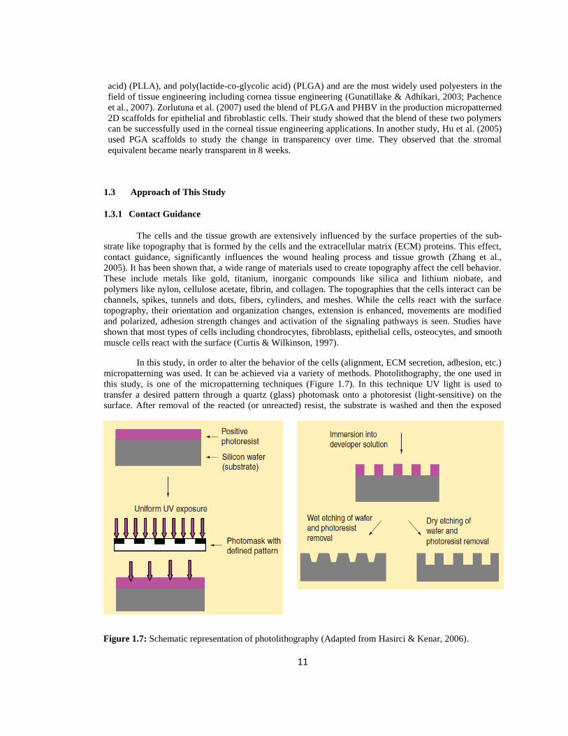
In this study, in order to alter the behavior of the cells (alignment, ECM secretion, adhesion, etc.)
micropatterning was used. It can be achieved via a variety of methods. Photolithography, the one used in
this study, is one of the micropatterning techniques (Figure 1.7). In this technique UV light is used to
transfer a desired pattern through a quartz (glass) photomask onto a photoresist (light-sensitive) on the
surface. After removal of the reacted (or unreacted) resist, the substrate is washed and then the exposed
Figure 1.7: Schematic representation of photolithography (Adapted from Hasirci & Kenar, 2006).

12
parts are etched. Thus, the material under the photoresist receives the patterns after further chemical
treatments (Falconnet et al., 2006; Subramani, 2010). If the final treatment is done by wet chemical
etching by using hydrofluoric acid, walls with slopes occur like the one used in this present study or
vertical walls are formed if the surface is etched by the reactive ions created by an electric field (Figure
1.7) (Hasirci & Kenar, 2006). The film to seed the cells on is obtained by using the etched substrate as a
template. The pattern on the film is then used to guide the cells for a successful tissue engineering
construct.
1.4 Novelty of This Study
Corneal stroma is composed of 200-400 lamellae parallel to corneal surface and at right angles to
the adjacent lamellae like plywood (Meek & Leonard, 1993). This alignment and orientation of the stroma
is vital for the maintenance of mechanical and optical properties of the cornea (Meek, 2009). In the present
study, the natural structure of the stroma was mimicked by using micropatterned collagen-based films that
helped alignment of the cells. These films were used in the construction of 3D, multilayered scaffolds by
stacking the micropatterned films perpendicular to adjacent films. Collagen has an important role in cell
attachment, proliferation and survival of the cells (Maurice, 1957; Wess, 2005). Elastin Like Recom-
binamers (ELR) are artificial protein based polymers produced by recombinant DNA technology.
Recently, they find increasing use in the field of tissue engineering due to their biocompatibility (Nair &
Laurencin, 2007). Studies conducted using ELRs with YIGSR sequences showed that this sequence
increased the cell binding, migration and proliferation of wide range of cells including endothelial cells,
epithelial cells, fibroblasts and smooth muscle cells (Fittkau et al., 2005). In this study these ELRs were
used for the first time with stromal keratocytes to improve cell adhesion and proliferation. Collagen and
ELR were used together in the construction of scaffolds which were stabilized with dehydrothermal
crosslinking and their in vitro performance was tested by using human corneal keratocytes.

13
CHAPTER 2
MATERIALS AND METHODS
2.1 Materials
Bovine serum albumin (BSA), sodium cacodylate trihydrate, glutaraldehyde (25%), 4’,6- diamine-
2-phenylindole dihydrochloride (DAPI), FITC-conjugated phalloidin, amphotericin B, Collagenase type II
from Clostridium Histolyticum, paraformaldehyde, monoclonal mouse anti-human collagen type I
antibody, and Coomassie brilliant blue were purchased from Sigma-Aldrich (USA). New born calf serum,
Dulbecco’s Modified Eagle Medium/ Ham’s Nutrient Mixture F12 (DMEM:F12, 1:1) with and without
Phenol red, Trypsin-EDTA (0.25%), Penicillin/Streptomycin, and SnakeSkin dialysis tubing were
obtained from HyClone, Thermo Scientific (USA). Ethanol, sodium dihydrogen phosphate dihydrate,
disodium hydrogen phosphate heptahydrate, acetic acid (HAc), sodium chloride, Anti-keratan sulfate
antibody, clone EFG-11 and goat anti-mouse IgG (H+L), Alexa Fluor® 488 conjugate were purchased
from Merck (Germany). Human basic fibroblast growth factor (hFGF basic/ FGF2) with carrier was
purchased from Cell Signaling Technology, Inc. (USA). Spectra ™ Multicolor broad range protein ladder
was obtained from Fermentas, Thermo Scientific (USA). Dimethyl sulfoxide (DMSO) and Triton X-100
were bought from AppliChem (USA). Alamar Blue was purchased from Invitrogen Inc (USA). Nucle-
oCasette was obtained from ChemoMetec (Denmark). Dithiothreitol (DTT) was bought from Bio-Rad
Laboratories (USA). Poly(dimethylsiloxane) (PDMS) precursor and curing agent (Sylgard 184) were
purchased from Dow Corning, USA.
Male Sprague-Dawley rat tails for isolation of collagen type I were kindly provided by Tayfun İde
(DVM), GATA Animal Experiments Laboratory (Turkey).
2.2 Methods
2.2.1 Collagen Type I Isolation
Collagen type I was isolated from male Spraque-Dawley rat tails as described previously
(Kinikoglu et al., 20011a). Briefly, the skins of tails were cut along their length, tendons were removed,
and dissolved in cold acetic acid (0.5 M) for 2-3 days at 4 oC. The suspension was filtered through glass
wool and dialyzed in a dialysis tubing (CO 10000) against phosphate buffer (5 L, 12.5 mM NaH2PO4, 11.5
mM Na2HPO4, pH 7.2) at 4 oC for 1 week by changing buffer daily. The resulting white solid precipitate
of collagen was centrifuged at 1600 g for 10 min (Sigma 3K30, Germany) and the pellet was dissolved
overnight at +4 oC in 0.15 M acetic acid, NaCl (25 g) was added, incubated overnight at 4
oC and centri-
fuged. The pellet was dissolved in 0.15 M acetic acid and dialyzed for 1 week against phosphate buffer
(pH 7.2) at 4 oC. The collagen pellets obtained following centrifugation were sterilized by storing in 70%
ethanol for 2 days. After centrifugation the pellet was frozen at -80 oC (Sanyo MDF-U53865, Japan) and
lyophilized (Labconco Freezone 6, USA) for 12 h. Yellowish collagen powder was stored at 4 oC.
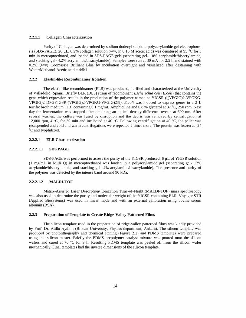
14
2.2.1.1 Collagen Characterization
Purity of Collagen was determined by sodium dodecyl sulphate-polyacrylamide gel electrophore-
sis (SDS-PAGE). 20 µL, 0.2% collagen solution (w/v, in 0.15 M acetic acid) was denatured at 95 oC for 3
min in mercaptoethanol, and loaded in SDS-PAGE gels (separating gel- 10% acrylamide/bisacrylamide,
and stacking gel- 4.2% acrylamide/bisacrylamide). Samples were run at 30 mA for 2.5 h and stained with
0.2% (w/v) Coomassie Brilliant Blue by incubation overnight and visualized after destaining with
Water:Methanol:Acetic acid = 4:5:1
2.2.2 Elastin-like Recombinamer Isolation
The elastin-like recombinamer (ELR) was produced, purified and characterized at the University
of Valladolid (Spain). Briefly BLR (DE3) strain of recombinant Escherichia coli (E.coli) that contains the
gene which expression results in the production of the polymer named as YIGSR ([(VPGIG)2-VPGKG-
VPGIG)2 DPGYIGSR-(VPGIG)2-VPGKG-VPGIG)2]8). E.coli was induced to express genes in a 2 L
terrific broth medium (TB) containing 0.1 mg/mL Amphiciline and 0.8 % glycerol at 37 oC, 250 rpm. Next
day the fermentation was stopped after obtaining an optical density difference over 4 at 600 nm. After
several washes, the culture was lysed by disruption and the debris was removed by centrifugation at
12,000 rpm, 4 oC, for 30 min and incubated at 40
oC. Following centrifugation at 40
oC, the pellet was
resuspended and cold and warm centrifugations were repeated 2 times more. The protein was frozen at -24 oC and lyophilized.
2.2.2.1 ELR Characterization
2.2.2.1.1 SDS PAGE
SDS-PAGE was performed to assess the purity of the YIGSR produced. 6 µL of YIGSR solution
(1 mg/mL in Milli Q) in mercaptoethanol was loaded in a polyacrylamide gel (separating gel- 12%
acrylamide/bisacrylamide, and stacking gel- 4% acrylamide/bisacrylamide). The presence and purity of
the polymer was detected by the intense band around 90 kDa.
2.2.2.1.2 MALDI-TOF
Matrix-Assisted Laser Desorption/ Ionization Time-of-Flight (MALDI-TOF) mass spectroscopy
was also used to determine the purity and molecular weight of the YIGSR containing ELR. Voyager STR
(Applied Biosystems) was used in linear mode and with an external calibration using bovine serum
albumin (BSA).
2.2.3 Preparation of Template to Create Ridge-Valley Patterned Films
The silicon template used in the preparation of ridge-valley patterned films was kindly provided
by Prof. Dr. Atilla Aydınlı (Bilkent University, Physics department, Ankara). The silicon template was
produced by photolithography and chemical etching (Figure 2.1) and PDMS templates were prepared
using this silicon master. Briefly the PDMS prepolymer-catalyst mixture was poured onto the silicon
wafers and cured at 70 oC for 3 h. Resulting PDMS template was peeled off from the silicon wafer
mechanically. Final templates had the inverse dimensions of the silicon template.
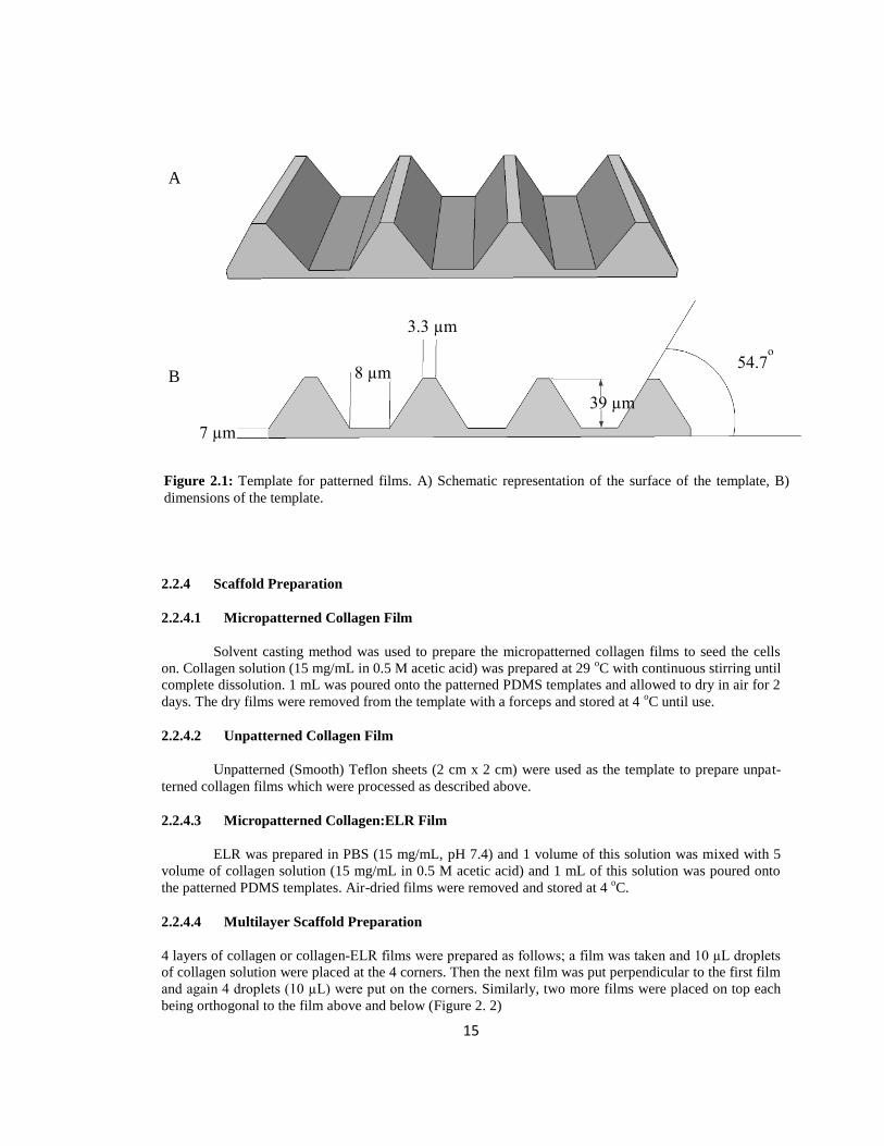
15
2.2.4 Scaffold Preparation
2.2.4.1 Micropatterned Collagen Film
Solvent casting method was used to prepare the micropatterned collagen films to seed the cells
on. Collagen solution (15 mg/mL in 0.5 M acetic acid) was prepared at 29 oC with continuous stirring until
complete dissolution. 1 mL was poured onto the patterned PDMS templates and allowed to dry in air for 2
days. The dry films were removed from the template with a forceps and stored at 4 oC until use.
2.2.4.2 Unpatterned Collagen Film
Unpatterned (Smooth) Teflon sheets (2 cm x 2 cm) were used as the template to prepare unpat-
terned collagen films which were processed as described above.
2.2.4.3 Micropatterned Collagen:ELR Film
ELR was prepared in PBS (15 mg/mL, pH 7.4) and 1 volume of this solution was mixed with 5
volume of collagen solution (15 mg/mL in 0.5 M acetic acid) and 1 mL of this solution was poured onto
the patterned PDMS templates. Air-dried films were removed and stored at 4 oC.
2.2.4.4 Multilayer Scaffold Preparation
4 layers of collagen or collagen-ELR films were prepared as follows; a film was taken and 10 µL droplets
of collagen solution were placed at the 4 corners. Then the next film was put perpendicular to the first film
and again 4 droplets (10 µL) were put on the corners. Similarly, two more films were placed on top each
being orthogonal to the film above and below (Figure 2. 2)
54.7o
39 µm
3.3 µm
8 µm
7 µm
A
B
Figure 2.1: Template for patterned films. A) Schematic representation of the surface of the template, B)
dimensions of the template.
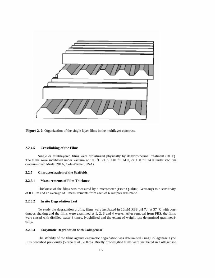
16
Figure 2. 2: Organization of the single layer films in the multilayer construct.
2.2.4.5 Crosslinking of the Films
Single or multilayered films were crosslinked physically by dehydrothermal treatment (DHT).
The films were incubated under vacuum at 105 oC 24 h, 140
oC 24 h, or 150
oC 24 h under vacuum
(vacuum oven Model 281A, Cole-Parmer, USA).
2.2.5 Characterization of the Scaffolds
2.2.5.1 Measurements of Film Thickness
Thickness of the films was measured by a micrometer (Erste Qualitat, Germany) to a sensitivity
of 0.1 µm and an average of 3 measurements from each of 6 samples was made.
2.2.5.2 In situ Degradation Test
To study the degradation profile, films were incubated in 10mM PBS pH 7.4 at 37 oC with con-
tinuous shaking and the films were examined at 1, 2, 3 and 4 weeks. After removal from PBS, the films
were rinsed with distilled water 3 times, lyophilized and the extent of weight loss determined gravimetri-
cally.
2.2.5.3 Enzymatic Degradation with Collagenase
The stability of the films against enzymatic degredation was determined using Collagenase Type
II as described previously (Vrana et al., 2007b). Briefly pre-weighed films were incubated in Collagenase
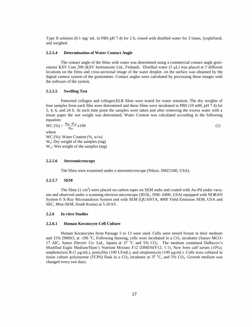
17
Type II solution (0.1 mg/ mL in PBS pH 7.4) for 2 h, rinsed with distilled water for 3 times, lyophilized,
and weighed.
2.2.5.4 Determination of Water Contact Angle
The contact angle of the films with water was determined using a commercial contact angle goni-
ometer KSV Cam 200 (KSV Instruments Ltd., Finland). Distilled water (5 µL) was placed at 5 different
locations on the films and cross-sectional image of the water droplet- on the surface was obtained by the
digital camera system of the goniometer. Contact angles were calculated by processing these images with
the software of the system.
2.2.5.5 Swelling Test
Patterned collagen and collagen:ELR films were tested for water retention. The dry weights of
four samples from each film were determined and these films were incubated in PBS (10 mM, pH 7.4) for
2, 4, 6, and 24 h. At each time point the samples were taken and after removing the excess water with a
tissue paper the wet weight was determined. Water Content was calculated according to the following
equation:
WC (%) =
x100 (1)
where
WC (%): Water Content (%, w/w)
Wd: Dry weight of the samples (mg)
Ww: Wet weight of the samples (mg)
2.2.5.6 Stereomicroscopy
The films were examined under a stereomicroscope (Nikon, SMZ1500, USA).
2.2.5.7 SEM
The films (1 cm2) were placed on carbon tapes on SEM stubs and coated with Au-Pd under vacu-
um and observed under a scanning electron microscope (JEOL, JSM- 6400, USA) equipped with NORAN
System 6 X-Ray Microanalysis System and with SEM (QUANTA, 400F Field Emission SEM, USA and
SEC, Mini-SEM, South Korea) at 5-20 kV.
2.2.6 In vitro Studies
2.2.6.1 Human Keratocyte Cell Culture
Human Keratocytes from Passage 5 to 13 were used. Cells were stored frozen in their medium
and 15% DMSO, at -196 oC. Following thawing, cells were incubated in a CO2 incubator (Sanyo MCO-
17 AIC, Sanyo Electric Co. Ltd., Japan) at 37 oC and 5% CO2. The medium contained Dulbecco’s
Modified Eagle Medium/Ham’s Nutrient Mixture F12 (DMEM/F12; 1:1), New born calf serum (10%),
amphotericin B (1 µg/mL), penicillin (100 UI/mL), and streptomycin (100 µg/mL). Cells were cultured in
tissue culture polystyrene (TCPS) flask in a CO2 incubator at 37 oC, and 5% CO2. Growth medium was
changed every two days.

18
2.2.6.2 Sterilization of the Scaffolds
Scaffolds crosslinked at 150 oC for 24 h were already sterile due to high temperature. Additional
sterilization was done by exposing both sides of the films to UV in a laminar flow hood for 15 min at
room temperature.
2.2.6.3 Cell Seeding onto the Scaffolds
Scaffolds were incubated in a sterile PBS pH 7.4 for 24 h to swell and then allowed to air-dry for
2-3 h to allow cell penetration. Cells were detached from the surface of TCPS flask by Trypsin-EDTA (1:1
0.25% EDTA: PBS pH 7.4) at 37 oC for 5 min, and the effect of trypsin was blocked with addition of
keratocyte growth medium and centrifuged at 3000 g for 5 min. After suspending the cells in the medium
cell number was determined via Nucleocounter (ChemoMetec, Denmark). Cells were seeded onto the
films at a density of 1x10⁴ cells/cm
2. For multilayer scaffolds 1x10
4 cells/cm
2 were seeded onto top and on
each of the other layers using an insulin syringe. The cell seeded scaffolds were incubated in a CO2
incubator at 37 oC for 2 h to allow the cells attach to the scaffolds. Finally, 2 mL of keratocyte growth
medium was put into each well which was changed every two days.
2.2.6.4 Alamar Blue Cell Viability Assay
Proliferation of the cells on the scaffolds was determined by Alamar Blue assay. Scaffolds were
washed twice with DMEM HAM’s F12 1:1 colorless and incubated in 10% Alamar Blue solution in
DMEM HAM’s F12 1:1 growth medium supplemented by amphotericin B (1µg/mL), penicillin (100
UI/mL), and streptomycin (100 µg/mL) for 1h at 37 oC and 5% CO2. After incubation the reduced solution
(200 μL) was transferred into 96-well plates, the scaffolds were washed twice with colorless medium,
keratocyte growth medium was added and then incubated. Intensity of the reduced dyes was determined at
570 and 595 nm by using an Elisa plate reader (Molecular Devices, USA). The absorbances were convert-
ed to percent reduction values and then to cell numbers using a calibration curve.
Percent reduction was calculated according to the following equation:
Reduction (%) = x100 (2)
where,
Aλ1= Absorbance of test well,
Aλ2= Absorbance of test well,
A′λ1= Absorbance of negative control well (blank)
A′λ2= Absorbance of negative control well.
)A x )(( - )A x )((
)A x )(( - )A x )((
12red21red
21oxox 12
λ1= 570 nm
(εox)λ2 = 117.216
(εox)λ1 = 80.586
λ2 = 595 nm
(εred)λ1 = 155.677
(εred)λ2 = 14.652

19
2.2.6.5 Microscopical Studies
2.2.6.5.1 Fluorescence Microscopy
2.2.6.5.1.1 DAPI-Phalloidin Staining
Single layer films were stained as they are while multilayer films were separated into single layer
films and then stained. Briefly, growth medium of the cells was discarded, fixed directly with 4% (w/v)
paraformaldehyde at room temperature for 30 min and cell membrane was permeabilized with Triton X-
100 (1% v/v in PBS pH 7.4) at room temperature for 5 min. After washing, samples were incubated in
BSA (1% w/v in PBS) at 37 oC for 30 min. FITC-labeled Phalloidin, (1:200 w/v, prepared in 0.1% BSA,
w/v in PBS), was added directly on the samples and they were stored at 37 oC for 1 h. After washing three
times with 0.1% BSA, the samples were incubated with DAPI (1:3000 w/v, in 0.1% BSA) for 5 min at 37 oC. Samples were washed with PBS three times and stored in PBS solution until examination using a
Zeiss Axio Imager M2 (Germany) fluorescent microscope.
2.2.6.5.2 SEM
Scaffolds were fixed with 2.5% v/v glutaraldehyde in cacodylate buffer pH 7.4 for 2 h at room
temperature. After washing several times with cacodylate buffer and distilled water, samples were
lyophilized and examined with SEM as described before.
Samples used for fluorescent microscopy analysis were washed with distilled water and observed with
SEM after lyophilization.
2.2.6.5.3 Confocal Laser Scanning Microscopy
2.2.6.5.3.1 Immunostaining
2.2.6.5.3.1.1 Collagen Type I Staining
Extracellular matrix (ECM) secretion of keratocytes was examined by indirect immunostaining of
collagen type I. Films were fixed in 2.5% formaldehyde for 15 min. After washing with PBS, cell
membranes were permeabilized by incubation in with 1% Triton X-100 for 5 min. After washing, samples
were incubated in 1% BSA w/v solution in PBS for 1 h at 37 oC. Anti-human collagen type I antibody
produced in mouse (1:200 dilution) in 0.1% w/v BSA in PBS was added onto the samples which were
incubated for 1 h at 37 oC. Samples were washed several times with 0.1% BSA and incubated with
AlexaFluor 488 conjugate anti-mouse antibody produced in goat (1:100 dilution) in 0.1% BSA for another
1 h at 37 oC. After washing with PBS, samples were stored in PBS at 4
oC. Samples were examined by
confocal laser scanning microscope (Zeiss LSM 9100, Germany) between 500-550 nm with 488 nm
Argon laser for collagen deposition and between 555-650 nm with 532 nm Argon laser for autofluores-
cence.
2.2.6.5.3.1.2 Keratan Sulfate Staining
Keratocyte specific proteoglycan keratan sulfate was determined by indirect keratan sulfate stain-
ing. Films were fixed in 2.5% formaldehyde for 15 min and then with 1% Triton X-100 for 5 min.
Samples were washed with PBS several times and incubated with 1% w/v BSA in PBS for 1 h at 37 oC.
After washing, anti-human keratan sulfate antibody produced in mouse (1:100 dilution) in 0.1% w/v in
PBS was added on the samples and incubated for 1 h at 37 oC. Samples were washed and incubated with
AlexaFluor 488 labeled anti-mouse antibody produced in goat (1:100 dilution) in 0.1% BSA (w/v in PBS)
at 37 oC for 1 h. After washing with PBS samples were stored in PBS at 4
oC and observed with a Zeiss

20
LSM 9100 (Germany) confocal laser scanning microscope between 500-550 nm with 488 nm Argon laser
for keratan sulfate deposition and between 555-650 nm with 532 nm Argon laser for autofluorescence.
2.2.6.6 Transparency of the Films
In order to determine the light transmittance of the films they were scanned in the range 250 nm-
700 nm by using Shimadzu 2100-S UV-Vis Spectrophotometer (Japan). Films were attached on the wall
of the quartz cuvette and their transparency was measured on days 0, 1, 20, and 30.
2.2.6.7 Mechanical Tests
Patterned collagen and collagen:ELR films were tested with an Instron 3366 tensile tester (Instron
Corp., USA) at 0.2 mm/min strain rate until failure. At least six specimens were used for each time point
(days 1 and 30). The dimensions for the test samples were 2 cm x 2 cm x 45 μm and the tests were done by
Prof. Ahmed El-Sheikh (University of Liverpool, UK) with his specially designed test rig.
2.2.7 Statistical Analysis
Statistical analysis was carried out by using the Student’s t-test; p values smaller or equal to 0.05
were considered statistically significant.

21
CHAPTER 3
RESULTS AND DISCUSSION
3.1 Collagen Type I Isolation and Purification
Collagen Type I was isolated from tails of Sprague-Dawley as previously described in Section
2.2.1. SDS-PAGE analysis was performed (Section 2.2.1.1) in order to demonstrate the purity of the
isolated collagen Type I. Middle lane shows the protein ladder with bands 260 kDa, 140 kDa, 100 kDa,
and 70 kDa from top to bottom. First and the third lanes show the isolated and commercial collagen,
respectively. Collagen type I has doublets at molecular weights of 115 and 130 kDa, and at 215 and 235
kDa (data sheet obtained from Sigma-Aldrich Co.). Isolated collagen had the same band pattern with
commercial collagen type I (Figure 3.1) and absence of other bands indicates the purity of the collagen
isolated from rat tail.
Figure 3.1: SDS-PAGE of collagen isolated from rat tail tendons.
MW Marker Isolated
Collagen Type I
Commercial
Collagen Type I
260 kDa
140 kDa
100 kDa
70 kDa
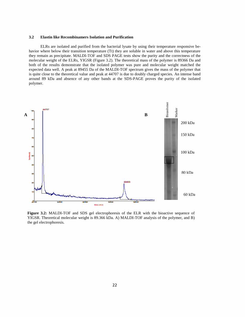
22
3.2 Elastin like Recombinamers Isolation and Purification
ELRs are isolated and purified from the bacterial lysate by using their temperature responsive be-
havior where below their transition temperature (Tt) they are soluble in water and above this temperature
they remain as precipitate. MALDI-TOF and SDS PAGE tests show the purity and the correctness of the
molecular weight of the ELRs, YIGSR (Figure 3.2). The theoretical mass of the polymer is 89366 Da and
both of the results demonstrate that the isolated polymer was pure and molecular weight matched the
expected data well. A peak at 89455 Da of the MALDI-TOF spectrum gives the mass of the polymer that
is quite close to the theoretical value and peak at 44707 is due to doubly charged species. An intense band
around 89 kDa and absence of any other bands at the SDS-PAGE proves the purity of the isolated
polymer.
Figure 3.2: MALDI-TOF and SDS gel electrophoresis of the ELR with the bioactive sequence of
YIGSR. Theoretical molecular weight is 89.366 kDa. A) MALDI-TOF analysis of the polymer, and B)
the gel electrophoresis.
200 kDa
150 kDa
100 kDa
80 kDa
60 kDa
Bio
po
lym
er
Mar
ker
A B
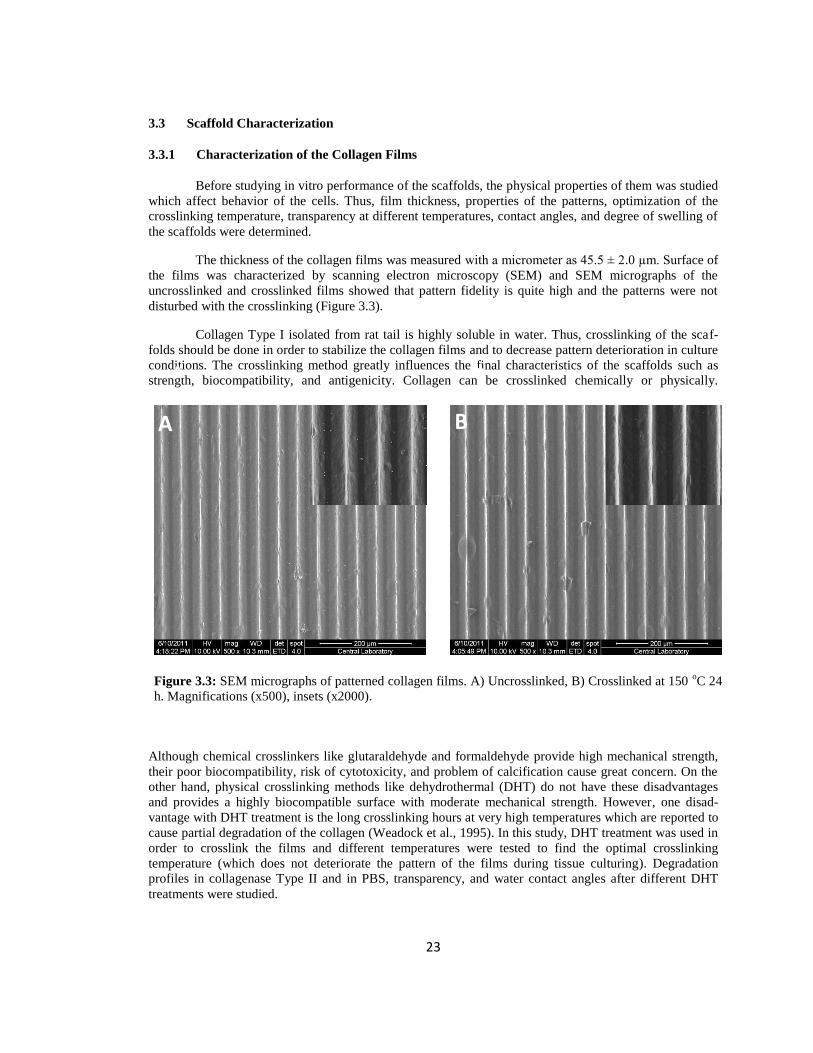
23
3.3 Scaffold Characterization
3.3.1 Characterization of the Collagen Films
Before studying in vitro performance of the scaffolds, the physical properties of them was studied
which affect behavior of the cells. Thus, film thickness, properties of the patterns, optimization of the
crosslinking temperature, transparency at different temperatures, contact angles, and degree of swelling of
the scaffolds were determined.
The thickness of the collagen films was measured with a micrometer as 45.5 ± 2.0 µm. Surface of
the films was characterized by scanning electron microscopy (SEM) and SEM micrographs of the
uncrosslinked and crosslinked films showed that pattern fidelity is quite high and the patterns were not
disturbed with the crosslinking (Figure 3.3).
Collagen Type I isolated from rat tail is highly soluble in water. Thus, crosslinking of the scaf-
folds should be done in order to stabilize the collagen films and to decrease pattern deterioration in culture
conditions. The crosslinking method greatly influences the final characteristics of the scaffolds such as
strength, biocompatibility, and antigenicity. Collagen can be crosslinked chemically or physically.
Although chemical crosslinkers like glutaraldehyde and formaldehyde provide high mechanical strength,
their poor biocompatibility, risk of cytotoxicity, and problem of calcification cause great concern. On the
other hand, physical crosslinking methods like dehydrothermal (DHT) do not have these disadvantages
and provides a highly biocompatible surface with moderate mechanical strength. However, one disad-
vantage with DHT treatment is the long crosslinking hours at very high temperatures which are reported to
cause partial degradation of the collagen (Weadock et al., 1995). In this study, DHT treatment was used in
order to crosslink the films and different temperatures were tested to find the optimal crosslinking
temperature (which does not deteriorate the pattern of the films during tissue culturing). Degradation
profiles in collagenase Type II and in PBS, transparency, and water contact angles after different DHT
treatments were studied.
A B
Figure 3.3: SEM micrographs of patterned collagen films. A) Uncrosslinked, B) Crosslinked at 150 oC 24
h. Magnifications (x500), insets (x2000).
A B

24
3.3.1.1 Enzymatic Degradation Profile of Films
Collagen fibrils of cornea are highly ordered and densely packed when compared to any other tis-
sue of the body. Cornea should be transparent to perform its function and this ordered structure and
avascularity of the cornea leads to its transparency. Corneal stromal keratocytes have an important role in
the collagen metabolism, both in the synthesis and the degradation of the collagen fibrils. The matrix
degrading enzymes and matrix metalloproteinases are produced by corneal keratocytes (Hao et al., 1999).
Thus, in order to preserve transparency and other vital functions of the cornea, the organization of the
scaffold should not be disrupted by the enzymes until the cells secrete their own ECM and compensates
for the degraded collagen. In this study, in order to test the stability of the films against proteolytic
enzymes, films were incubated with collagenase type II (Figure 3.4) Uncrosslinked films (UXL) and films
crosslinked at 105 oC for 24 h (DHT105) degraded totally after 2 h incubation with the collagenase, but
films crosslinked at 140 oC (DHT140) and 150
oC (DHT150) for 24 h resisted to degradation to some
extent. When compared with DHT140 films (28% remained), the DHT150 films were very stable (88%
remained). As a control, PBS (pH 7.4) was used as the degradation medium and the films retained their
forms in PBS during 2 h incubation except UXL films where only a very small portion (21%) of the films
was remained (Figure 3.4). Thus, experiments in the degradation medium showed that in situ degradation
of the films at this 2 h interval was negligible.
The effect of the proteolytic enzymes on the patterns was also studied with scanning electron mi-
croscopy (SEM) (Figure 3.5). UXL and DHT105 films were totally degraded. The patterns of the DHT140
films were highly deteriorated and the collagen fragments were seen all over the surface (Figure 3.5 A).
On the other hand, the patterns on the DHT150 films were conserved and no collagen fragments were
observed. Although the pattern features were not as sharp as the untreated ones (Figure 3.3), the main form
and the dimensions of the patterns were not affected after such a vigorous hydrolytic treatment (Figure 3.5
B).
0
10
20
30
40
50
60
70
80
90
100
1 2 3 4
We
igh
t R
em
ain
ed
(%
)
Samples
in PBS
in Collagenase type II
UXL DHT105 DHT140 DHT150
Figure 3.4: Degradation profile of the crosslinked patterned collagen films in PBS, pH 7.4 and in
collagenase type II solution (0.1 mg/mL in PBS pH 7.4) at 37 oC, after 2 h.
25
The surface of the films was also studied after incubation in a milder environment, PBS pH 7.4 for 2 h
(Figure 3.6). Although UXL film did not degrade totally in PBS after 2 h, there were missing the patterns
and fragments (Figure 3.6 A). The patterns of the DHT105 films were also deteriorated in PBS, however,
they still retained their pattern form and dimensions (Figure 3.6 B). DHT140 and DHT150 films were not
affected by PBS (Figure 3.6 C, D).
Figure 3.5: SEM micrographs of the films after 2h treatment with collagenase. A) DHT140 film, and B)
DHT150 film. Inset magnifications are x2000.
A B
A B
>

26
3.3.1.2 In situ Degradation Test
The degradation profile of the scaffolds in culture conditions and in the integration with the host
tissue is an important property since the rate of the degradation affects the performance of the scaffold that
it should carry out until it is fully compensated by the ECM products. If degradation occurs too fast, the
structural support may not be provided due to insufficient number of cells and protein matrix ingrowth
from the neighboring healthy tissue. On the other hand, if the degradation proceeds too slowly, the
scaffold can be recognized as a foreign material and inflammation is started which results in scaffold
rejection (Williams et al., 1999). In order to mimic the culture conditions, crosslinked and uncrosslinked
films were incubated in PBS (pH 7.4, 37 oC) for 4 weeks (Figure 3.7). While UXL films degraded
completely in one week, crosslinked ones resisted degradation for much longer. Among the crosslinked
films, DHT150 was the most stable in the weight of which there was a small decrease. In the first week it
lost 15% of its weight and at the end of fourth week the loss was 18%. DHT140 was also stable but not as
much as DHT150; it lost 28% of its weight in the first week and this loss was 38% at the end of 4th
week.
DHT105 was the least stable among the crosslinked films where after 4 weeks only 15% of the film was
remained.
A B
C D
Figure 3.6: SEM micrographs of patterned films after 2h incubation in PBS (pH 7.4). A) UXL Film,
B) DHT105 film, C) DHT140 film, and D) DHT150 film. Magnifications (x500), insets (x2000).

27
3.3.1.3 Transparency Measurements
Cornea is avascular and it is transparent which are among its most important properties. Cornea
transmits more than 90% of the light in the visible spectrum (Jester, 2008) and therefore any corneal
equivalent should be transparent enough to be used in place of the natural cornea. In order to study
transparency, the light transmittance of the films was measured in the range 250-700 nm and all the films
showed light transmittance in between 77-85% (Figure 3.8). In the visible range, UXL films had the
highest light transmittance (85%) and significantly different from others (p≤0.05). The DHT105 and
DHT140 films showed about 80% of transmittance, while DHT150 films showed the lowest transmittance
which was still around 77%. Although the difference in light transmittance of DHT105 and DHT140 was
not significant, this small decrease could be explained with an increase in crosslinking which decreased
the hydration of the films. Additionally, with increasing temperature a slight yellowish color (probably a
result of oxidation) was observed in the films which also be explained with incubation at high tempera-
tures and this also may be another reason for the decrease in transmittance.
Figure 3.7: In situ degradation profile of the crosslinked and uncrosslinked films incubated for 4 weeks in
PBS (pH 7.4, 37 oC).
0
20
40
60
80
100
120
0 7 14 21 28
We
igh
t R
em
ain
ed
(%
)
Time (days)
UXL
DHT105
DHT140
DHT150
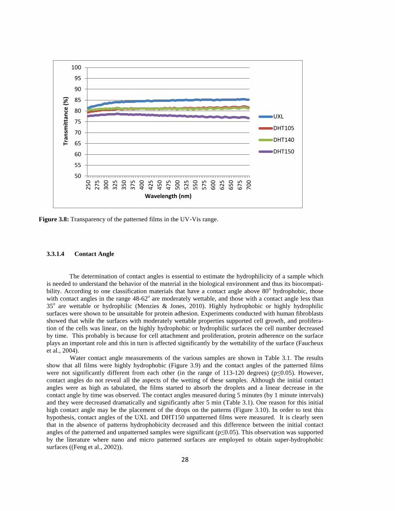
28
3.3.1.4 Contact Angle
The determination of contact angles is essential to estimate the hydrophilicity of a sample which
is needed to understand the behavior of the material in the biological environment and thus its biocompati-
bility. According to one classification materials that have a contact angle above 80o hydrophobic, those
with contact angles in the range 48-62o are moderately wettable, and those with a contact angle less than
35o are wettable or hydrophilic (Menzies & Jones, 2010). Highly hydrophobic or highly hydrophilic
surfaces were shown to be unsuitable for protein adhesion. Experiments conducted with human fibroblasts
showed that while the surfaces with moderately wettable properties supported cell growth, and prolifera-
tion of the cells was linear, on the highly hydrophobic or hydrophilic surfaces the cell number decreased
by time. This probably is because for cell attachment and proliferation, protein adherence on the surface
plays an important role and this in turn is affected significantly by the wettability of the surface (Faucheux
et al., 2004).
Water contact angle measurements of the various samples are shown in Table 3.1. The results
show that all films were highly hydrophobic (Figure 3.9) and the contact angles of the patterned films
were not significantly different from each other (in the range of 113-120 degrees) (p≤0.05). However,
contact angles do not reveal all the aspects of the wetting of these samples. Although the initial contact
angles were as high as tabulated, the films started to absorb the droplets and a linear decrease in the
contact angle by time was observed. The contact angles measured during 5 minutes (by 1 minute intervals)
and they were decreased dramatically and significantly after 5 min (Table 3.1). One reason for this initial
high contact angle may be the placement of the drops on the patterns (Figure 3.10). In order to test this
hypothesis, contact angles of the UXL and DHT150 unpatterned films were measured. It is clearly seen
that in the absence of patterns hydrophobicity decreased and this difference between the initial contact
angles of the patterned and unpatterned samples were significant (p≤0.05). This observation was supported
by the literature where nano and micro patterned surfaces are employed to obtain super-hydrophobic
surfaces ((Feng et al., 2002)).
Figure 3.8: Transparency of the patterned films in the UV-Vis range.
50
55
60
65
70
75
80
85
90
95
100
25
0
27
5
30
0
32
5
35
0
37
5
40
0
42
5
45
0
47
5
50
0
52
5
55
0
57
5
60
0
62
5
65
0
67
5
70
0
Tra
nsm
itta
nce
(%
)
Wavelength (nm)
UXL
DHT105
DHT140
DHT150

29
Sample Contact angle (deg) Contact angle (deg) after 5
min.
UXL Patterned 114.82 ± 7.99 102.34 ± 9.28
UXL Unpatterned 98.09 ± 0.84 88.33 ± 4.92
DHT105 113.52 ± 2.74 103.02 ± 7.44
DHT140 119.16 ± 4.09 106.33 ± 6.72
DHT150 117.13 ± 1.19 106.80 ± 4.53
DHT150 Unpatterned 95.61 ± 2.48 82.57 ± 1.22
Table 3.1: Contact angle measurements of collagen films at different temperatures
Figure 3.9: Water contact angles of collagen films. A) UXL unpatterned, B) UXL patterned, C)
DHT105, D) DHT140, E) DHT150, and F) DHT150 unpatterned.
B C
D E
A
F
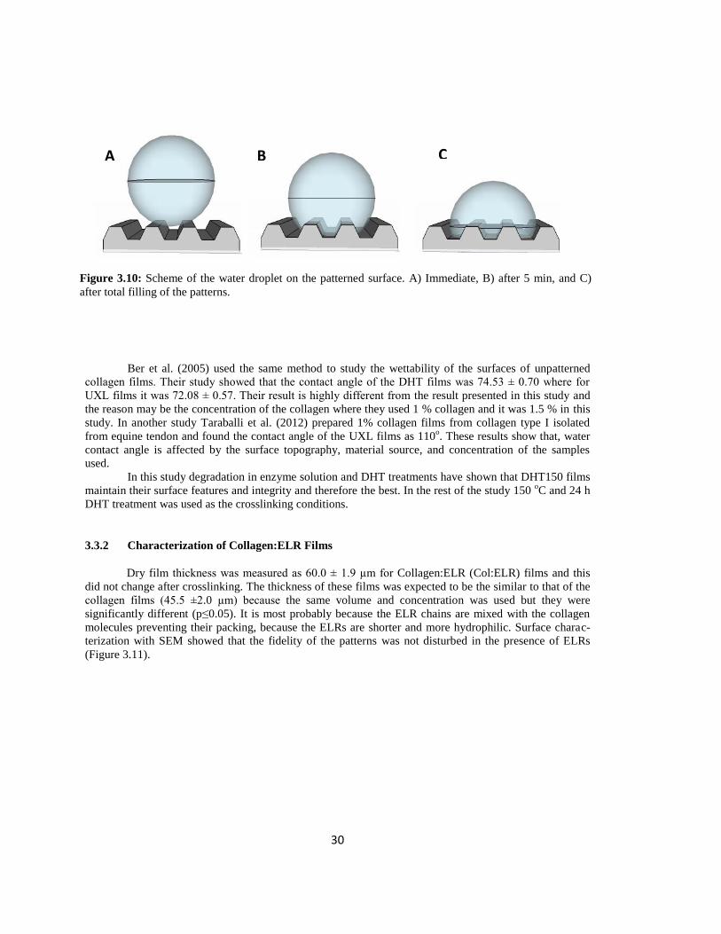
30
Ber et al. (2005) used the same method to study the wettability of the surfaces of unpatterned
collagen films. Their study showed that the contact angle of the DHT films was 74.53 ± 0.70 where for
UXL films it was 72.08 ± 0.57. Their result is highly different from the result presented in this study and
the reason may be the concentration of the collagen where they used 1 % collagen and it was 1.5 % in this
study. In another study Taraballi et al. (2012) prepared 1% collagen films from collagen type I isolated
from equine tendon and found the contact angle of the UXL films as 110o. These results show that, water
contact angle is affected by the surface topography, material source, and concentration of the samples
used.
In this study degradation in enzyme solution and DHT treatments have shown that DHT150 films
maintain their surface features and integrity and therefore the best. In the rest of the study 150 oC and 24 h
DHT treatment was used as the crosslinking conditions.
3.3.2 Characterization of Collagen:ELR Films
Dry film thickness was measured as 60.0 ± 1.9 µm for Collagen:ELR (Col:ELR) films and this
did not change after crosslinking. The thickness of these films was expected to be the similar to that of the
collagen films (45.5 ±2.0 µm) because the same volume and concentration was used but they were
significantly different (p≤0.05). It is most probably because the ELR chains are mixed with the collagen
molecules preventing their packing, because the ELRs are shorter and more hydrophilic. Surface charac-
terization with SEM showed that the fidelity of the patterns was not disturbed in the presence of ELRs
(Figure 3.11).
Figure 3.10: Scheme of the water droplet on the patterned surface. A) Immediate, B) after 5 min, and C)
after total filling of the patterns.
A B C

31
Figure 3.11: SEM micrograph of uncrosslinked Col:ELR films. Magnifications (x50), insets (x150).

32
3.3.2.1 Collagenase Stability of the Col:ELR films
Enzymatic degradation of Col:ELR films was studied (Figure 3.12). According to the results,
85.48% of the weight remained after 2 h where it was quite similar for collagen films (88.12%) and the
difference was not significant (p≤0.05) which shows that the presence of ELR in the structure did not
affect susceptibility to enzymatic attack. UXL Col and Col:ELR films, on the other hand, were degraded
totally after 2h enzyme treatment.
Figure 3.12: Degradation profile of patterned Col and Col:ELR films in collagenase type II solution (0.1
mg/mL in PBS, pH 7.4) at 37 oC, after 2 h.
0
10
20
30
40
50
60
70
80
90
100
1 2 3 4
We
igh
t R
em
ain
ed
(%
)
Samples
UXL Col DHT150 Col UXL Col:ELR DHT150 Col:ELR

33
3.3.2.2 In situ Degradation Test
The stability of the Col:ELR films in the culturing conditions was tested by incubation of the films in PBS
(37 oC , pH 7.4) for 4 weeks. The results for crosslinked samples presented in Figure 3.13 show first a
distinct decrease of about 20% which was followed by a steady decrease for 3 weeks. On the whole 82%
of the DHT150 Col films remained after 4 weeks while 67% of DHT150 Col:ELR films remained.
Although the DHT150 Col:ELR films seems to have a higher degradation rate than DHT150 Col films, the
remaining weight (%) after 4 weeks was still higher than other DHT films (Section 3.3.1.2). The reason
why the DHT150 Col:ELR films had higher degradation rate may be the less effective crosslinking of
Col:ELR films because ELR was homogenously mixed with the collagen molecules and the interaction
between the collagen molecules was disturbed which must have prevented further crosslinking. Also the
shorter ELR chains may have gradually dissolved in water leaving behind only collagen. Meanwhile, the
UXL forms of both films degraded totally in the first week.
Figure 3.13: In situ degradation profile of the patterned films incubated for 4 weeks in PBS (pH 7.4, 37 oC).
0
20
40
60
80
100
120
0 5 10 15 20 25 30
We
igh
t R
em
ain
ed
(%
)
Time (days)
UXL Col
UXL Col:ELR
DHT150 Col
DHT150 Col:ELR

34
3.3.2.3 Transparency Measurements
The light transmittance of the Col:ELR films was measured in the UV-Vis range 250 nm- 700 nm and the
spectrum is presented along with those of UXL Col and DHT150 Col films (Figure 3.14). The results
show that incorporation of ELR into the structure increased the light transmittance in comparison to Col
film. Light transmittance at 700 nm for DHT150 Col:ELR films has 83 % while it was 77 % for DHT150
Col films and 85 % for UXL Col films. When compared to other DHT films (Section 3.3.1.3), ELR
enhanced the transmission of light especially in the visible range.
In order to have a visual proof of the transparency of the films, stereomicrographs of the films in hydrated
state were taken (Figure 3.15). As can be seen in the micrographs, DHT150 Col:ELR films are more
transparent than others because the letters appear sharper.
Figure 3.14: Transparency of the patterned Col and Col:ELR films in the UV-Vis range
50
55
60
65
70
75
80
85
90
95
100
25
0
27
5
30
0
32
5
35
0
37
5
40
0
42
5
45
0
47
5
50
0
52
5
55
0
57
5
60
0
62
5
65
0
67
5
70
0
Tran
smit
tan
ce (
%)
Wavelength (nm)
UXL Col
DHT150 Col
DHT150 Col:ELR
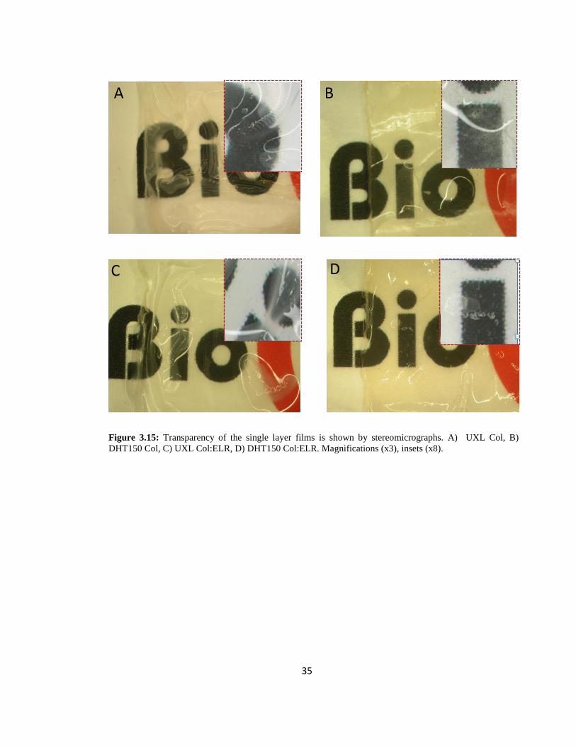
35
Figure 3.15: Transparency of the single layer films is shown by stereomicrographs. A) UXL Col, B)
DHT150 Col, C) UXL Col:ELR, D) DHT150 Col:ELR. Magnifications (x3), insets (x8).
A B
C D
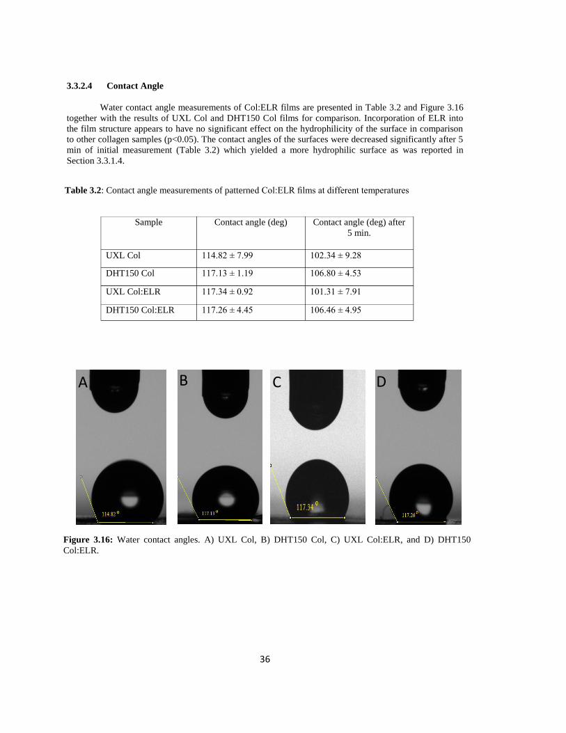
36
3.3.2.4 Contact Angle
Water contact angle measurements of Col:ELR films are presented in Table 3.2 and Figure 3.16
together with the results of UXL Col and DHT150 Col films for comparison. Incorporation of ELR into
the film structure appears to have no significant effect on the hydrophilicity of the surface in comparison
to other collagen samples (p<0.05). The contact angles of the surfaces were decreased significantly after 5
min of initial measurement (Table 3.2) which yielded a more hydrophilic surface as was reported in
Section 3.3.1.4.
Sample Contact angle (deg) Contact angle (deg) after
5 min.
UXL Col 114.82 ± 7.99 102.34 ± 9.28
DHT150 Col 117.13 ± 1.19 106.80 ± 4.53
UXL Col:ELR 117.34 ± 0.92 101.31 ± 7.91
DHT150 Col:ELR 117.26 ± 4.45 106.46 ± 4.95
Table 3.2: Contact angle measurements of patterned Col:ELR films at different temperatures
Figure 3.16: Water contact angles. A) UXL Col, B) DHT150 Col, C) UXL Col:ELR, and D) DHT150
Col:ELR.
A B C D C
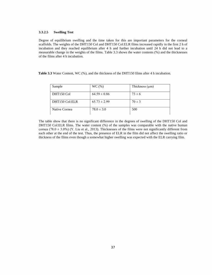
37
3.3.2.5 Swelling Test
Degree of equilibrium swelling and the time taken for this are important parameters for the corneal
scaffolds. The weights of the DHT150 Col and DHT150 Col:ELR films increased rapidly in the first 2 h of
incubation and they reached equilibrium after 4 h and further incubation until 24 h did not lead to a
measurable change in the weights of the films. Table 3.3 shows the water contents (%) and the thicknesses
of the films after 4 h incubation.
The table show that there is no significant difference in the degrees of swelling of the DHT150 Col and
DHT150 Col:ELR films. The water content (%) of the samples was comparable with the native human
cornea (78.0 ± 3.0%) (Y. Liu et al., 2013). Thicknesses of the films were not significantly different from
each other at the end of the test. Thus, the presence of ELR in the film did not affect the swelling ratio or
thickness of the films even though a somewhat higher swelling was expected with the ELR carrying film.
Sample WC (%) Thickness (µm)
DHT150 Col 64.59 ± 0.86 73 ± 6
DHT150 Col:ELR 65.73 ± 2.99 70 ± 3
Native Cornea 78.0 ± 3.0 500
Table 3.3 Water Content, WC (%), and the thickness of the DHT150 films after 4 h incubation.

38
3.3.3 Characterization of Multilayer Scaffolds
Stroma of the natural cornea has lamellae which are parallel to the surface of the cornea and at right angles
to adjacent lamellae like in plywood (Section 1.1.1.2). This and the resultant alignment of the cells are
very important for the mechanical and optical properties of the cornea (Meek, 2009). Thus, in order to
mimic the natural structure of the corneal stroma, multilayer 3D scaffolds were constructed by stacking
four single layers of UXL Col or Col:ELR films (Figure 3.17). In order to stabilize the films in this form
collagen solution was placed at the four corners of the first film and the second film was placed on top
with its patterns orthogonal to those of the first film. Two more films were placed on top of each other in a
similar fashion.
Natural corneal stroma is around 400 µm thick while the multilayer structure constructed in this study was
about 200 µm in dry state and about 300 µm in wet state. Only four layers were used for ease of construc-
tion and in vitro studies.
Transparency of the stacked scaffold was assessed by stereomicroscopy and when compared with the
single layers films it was observed that the transparency was better in the single films. Yellowish color
was seen in crosslinked samples which decrease transparency in comparison to uncrosslinked scaffolds
(Figure 3.18). DHT150 Col:ELR films yielded better transparency then DHT150 Col films because the
letters were sharper.
Figure 3.17: Stereomicrograph of multilayer scaffold with 4 layers of UXL Col film. Magnification: x45.
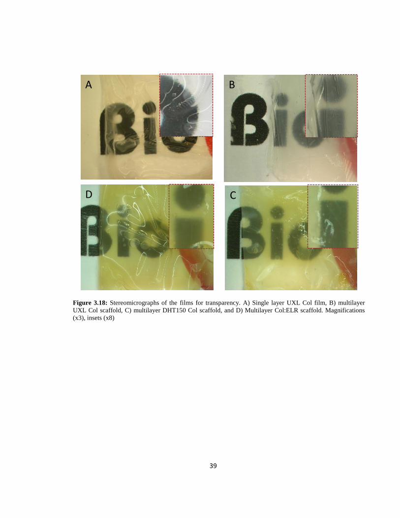
39
Figure 3.18: Stereomicrographs of the films for transparency. A) Single layer UXL Col film, B) multilayer
UXL Col scaffold, C) multilayer DHT150 Col scaffold, and D) Multilayer Col:ELR scaffold. Magnifications
(x3), insets (x8)
A B
C D

40
3.4 In vitro studies
3.4.1 Single Layer Films
3.4.1.1 Cell Proliferation
Cell proliferation was determined by using the Alamar Blue assay. The number of cells on both the films
was practically same for the duration of the test (3 weeks) (Figure 3.19). None of the films appeared to be
superior to the other neither in cell adhesion nor in proliferation. The main observation was that the cell
growth curve was triphasic: an initial linear increase in the first week, a very slow increase in the second
week and then a very rapid cell proliferation in the third week. This higher proliferation in the 3rd
week
can be because of the ECM secretion of the cells which creates more area for the cells to proliferate on; an
indication of this was observed by the fluorescence microscope. Gil et al. (2010) used RGD- functional-
ized, patterned silk films which were seeded with human corneal keratocytes. The cell number showed a
linear increase in the 14 day period. In another study, Lawrence et al. (2009) reported a similar result for a
6 day culture for human keratocytes seeded on silk films. However, both studies lack the 3rd
week data
where in this study a sharp increase was observed between Days 14 and 21.
Figure 3.19: Proliferation of keratocytes on Col and Col:ELR films in 3 weeks. (Initial cell seeding density
per sample: 4x10⁴)
0
100000
200000
300000
400000
500000
600000
700000
800000
0 5 10 15 20 25
Ce
ll N
um
be
r
Time (Days)
Col:ELR film
Col film
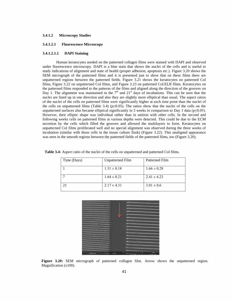
41
3.4.1.2 Microscopy Studies
3.4.1.2.1 Fluorescence Microscopy
3.4.1.2.1.1 DAPI Staining
Human keratocytes seeded on the patterned collagen films were stained with DAPI and observed
under fluorescence microscopy. DAPI is a blue stain that shows the nuclei of the cells and is useful to
study indications of alignment and state of health (proper adhesion, apoptosis etc.). Figure 3.20 shows the
SEM micrograph of the patterned films and it is presented just to show that on these films there are
unpatterned regions between the patterned fields. Figure 3.21 shows the keratocytes on patterned Col
films, Figure 3.22 on unpatterned Col films, and Figure 3.23 on patterned Col:ELR films. Keratocytes on
the patterned films responded to the patterns of the films and aligned along the direction of the grooves on
Day 1. The alignment was maintained in the 7th
and 21st days of incubations. This can be seen that the
nuclei are lined up in one direction and also they are slightly more elliptical than usual. The aspect ratios
of the nuclei of the cells on patterned films were significantly higher at each time point than the nuclei of
the cells on unpatterned films (Table 3.4) (p≤0.05). The ratios show that the nuclei of the cells on the
unpatterned surfaces also became elliptical significantly in 3 weeks in comparison to Day 1 data (p≤0.05).
However, their elliptic shape was individual rather than in unition with other cells. In the second and
following weeks cells on patterned films at various depths were detected. This could be due to the ECM
secretion by the cells which filled the grooves and allowed the multilayers to form. Keratocytes on
unpatterned Col films proliferated well and no special alignment was observed during the three weeks of
incubation (similar with those cells in the tissue culture flask) (Figure 3.22). This unaligned appearance
was seen in the smooth regions between the patterned fields of the patterned films, too (Figure 3.20).
Time (Days) Unpatterned Film Patterned Film
1 1.31 ± 0.18 1.66 ± 0.28
7 1.64 ± 0.21 2.41 ± 4.23
21 2.17 ± 4.31 3.01 ± 0.6
Figure 3.20: SEM micrograph of patterned collagen film. Arrow shows the unpatterned region.
Magnification (x100).
Table 3.4: Aspect ratio of the nuclei of the cells on unpatterned and patterned Col films.

42
A B
C D
E F
Figure 3.21: Fluorescence micrographs of DAPI stained human keratocytes on patterned Col films. Time of
incubation (days): A, B) 1, C, D) 7, and E, F) 21. Scale bars: 50 µm.
Day 1
Day 7
Day 21

43
Figure 3.22: Fluorescence micrographs of DAPI stained human keratocytes on unpatterned Col films.
Time of incubation (days): A, B) 1, C, D) 7, and E, F) 21. Scale bars: 50 µm.
A B
C D
E F
Day 1
Day 7
Day 21
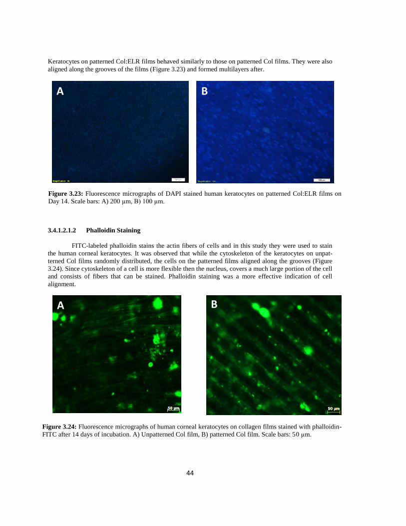
44
A B
Figure 3.24: Fluorescence micrographs of human corneal keratocytes on collagen films stained with phalloidin-
FITC after 14 days of incubation. A) Unpatterned Col film, B) patterned Col film. Scale bars: 50 µm.
Keratocytes on patterned Col:ELR films behaved similarly to those on patterned Col films. They were also
aligned along the grooves of the films (Figure 3.23) and formed multilayers after.
3.4.1.2.1.2 Phalloidin Staining
FITC-labeled phalloidin stains the actin fibers of cells and in this study they were used to stain
the human corneal keratocytes. It was observed that while the cytoskeleton of the keratocytes on unpat-
terned Col films randomly distributed, the cells on the patterned films aligned along the grooves (Figure
3.24). Since cytoskeleton of a cell is more flexible then the nucleus, covers a much large portion of the cell
and consists of fibers that can be stained. Phalloidin staining was a more effective indication of cell
alignment.
A B
Figure 3.23: Fluorescence micrographs of DAPI stained human keratocytes on patterned Col:ELR films on
Day 14. Scale bars: A) 200 µm, B) 100 µm.

45
A B B
C D
Figure 3.25: Behavior of human corneal keratocytes. A-C) Fluorescence micrograph of human
corneal keratocytes on unpatterned Col films stained with phalloidin-FITC on day 14. Scale bar is: A)
100 µm, B, C) 20 µm. D) Phase contrast image of human corneal keratocytes on transwell membrane
after 1 week. Scale bar: 20 µm (Adapted from Guo et al., 2007).
Cells on unpatterned films also showed regions of but these regions were not continuous and con-
stituted patches on the surface aligned in different directions (Figure 3.25 A). This was very similar to the
behavior of the cells on the tissue culture flasks (Figure 3.25 D) (Guo et al., 2007). Interestingly, after
reaching confluency, the second layer of cells grew almost perpendicular to the first layer of the cells. This
was not observed in the patterned collagen films where the multilayer of cells continued to grow along the
patterns (within the grooves) (Figure 3.24 B). This aligned behavior of the cells on the patterned films
allows one to control the orientation of the cells on the multilayer constructs.
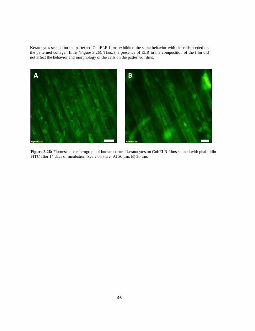
46
Keratocytes seeded on the patterned Col:ELR films exhibited the same behavior with the cells seeded on
the patterned collagen films (Figure 3.26). Thus, the presence of ELR in the composition of the film did
not affect the behavior and morphology of the cells on the patterned films.
A B
Figure 3.26: Fluorescence micrograph of human corneal keratocytes on Col:ELR films stained with phalloidin
FITC after 14 days of incubation. Scale bars are: A) 50 µm, B) 20 µm.
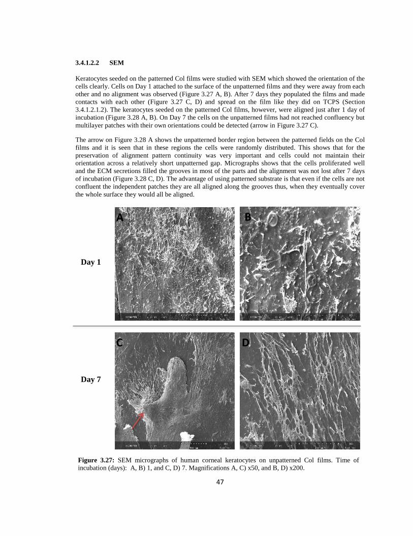
47
3.4.1.2.2 SEM
Keratocytes seeded on the patterned Col films were studied with SEM which showed the orientation of the
cells clearly. Cells on Day 1 attached to the surface of the unpatterned films and they were away from each
other and no alignment was observed (Figure 3.27 A, B). After 7 days they populated the films and made
contacts with each other (Figure 3.27 C, D) and spread on the film like they did on TCPS (Section
3.4.1.2.1.2). The keratocytes seeded on the patterned Col films, however, were aligned just after 1 day of
incubation (Figure 3.28 A, B). On Day 7 the cells on the unpatterned films had not reached confluency but
multilayer patches with their own orientations could be detected (arrow in Figure 3.27 C).
The arrow on Figure 3.28 A shows the unpatterned border region between the patterned fields on the Col
films and it is seen that in these regions the cells were randomly distributed. This shows that for the
preservation of alignment pattern continuity was very important and cells could not maintain their
orientation across a relatively short unpatterned gap. Micrographs shows that the cells proliferated well
and the ECM secretions filled the grooves in most of the parts and the alignment was not lost after 7 days
of incubation (Figure 3.28 C, D). The advantage of using patterned substrate is that even if the cells are not
confluent the independent patches they are all aligned along the grooves thus, when they eventually cover
the whole surface they would all be aligned.
A B
C D
Figure 3.27: SEM micrographs of human corneal keratocytes on unpatterned Col films. Time of
incubation (days): A, B) 1, and C, D) 7. Magnifications A, C) x50, and B, D) x200.
Day 1
Day 7
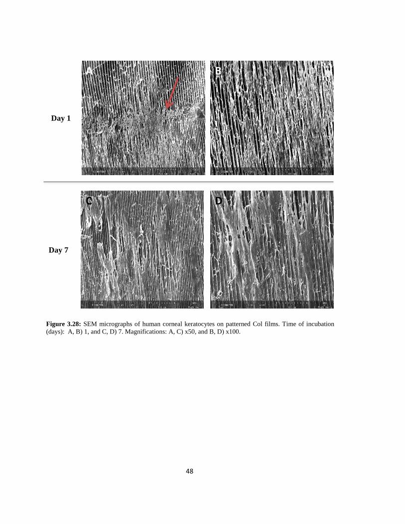
48
A B
C D
Figure 3.28: SEM micrographs of human corneal keratocytes on patterned Col films. Time of incubation
(days): A, B) 1, and C, D) 7. Magnifications: A, C) x50, and B, D) x100.
Day 7
Day 1
49
3.4.1.3 Transparency Measurements
Transparency is very important for the artificial cornea constructs to fulfill function properly.
Transparency of the natural cornea is provided by ECM and keratocytes. ECM contributes to the transpar-
ency with its proteoglycans and the organization of the collagen fibrils and keratocytes keep the cornea
transparent by the continuous synthesis of proteoglycans and crystalline proteins (Maurice, 1957; Ruberti
et al., 2007). Thus, the transparency of the any cornea equivalent should be improved by the corneal
keratocytes over time by proteoglycan and crystalline protein synthesis to match that of the native cornea.
Patterned Col and Col:ELR films were tested in vitro over one month for their transparency.
In the first day, the wet Col films had 80 % transmittance in the visible range (700 nm), and the
Col:ELR films had 85 % (Figure 3.29 A). In three weeks transparency of Col films increased to 87% and
to 92 % after 30 days. Transparency of the Col:ELR films was higher than that of the Col films at each
time point; 91% on the third week and 93% on 30th
day (Figure 3.29 B, C). Both these values are compa-
rable with that of the native cornea where the transmittance is 98 % at 700 nm (Meek et al., 2003; Shah et
al., 2008). Thus, incorporation of ELR into the structure slightly enhanced the transparency of the collagen
constructs. The transparency for both types, however, was increased by almost 5% over a 30 day period.
The increase in the transparency of both films was due to an increase in the organization of the films and
the alignment of the cells over the grooves. The crosslinking method, DHT, probably also contributed to
the transparency of the films since studies conducted with other crosslinking agents like glutaraldehyde, 1-
ethyl-3-(3-dimethylaminopropyl) carbodiimide hydrochloride (EDC), and cyanamide resulted in opaque
films with much higher swelling degrees than with DHT crosslinking (Crabb & Hubel, 2008). Degradation
of the films during this period may also contribute to the increase in transparency, however, the in situ
degradation was not so high over the 1 month test period and besides the ECM secretion and the prolifera-
tion of the cells on the films probably compensated this loss. For comparison transmittance (%) at 700 nm
of 0 (unseeded), 1, 20, and 30 days for both films were given in Figure 3.30 in order to view the improve-
ment over time better.

50
Figure 3.29: Transparency of the Col and Col:ELR films. Days A) 1, B) 20, and C) 30. Transparency of
the films was compared with transparency of native cornea (Meek et al., 2003).
B
A
C
50
60
70
80
90
100
250 450 650 850
Tran
smit
tan
ce (
%)
Wavelength (nm)
Col
Col:ELR
Native Cornea
50
60
70
80
90
100
250 450 650 850
Tran
smit
tan
ce (
%)
Wavelength (nm)
Col
Col:ELR
Native Cornea
50
60
70
80
90
100
250 450 650 850
Tran
smit
tan
ce (
%)
Wavelength (nm)
Col
Col:ELR
Native Cornea
Day 1
Day 20
Day 30

51
3.4.1.4 Mechanical Tests
Mechanical properties of the scaffold are also very important in tissue engineering because the cells sense
and respond the mechanical features of the surfaces they attach to. The mechanical properties of the
surface influence the orientation, proliferation, and differentiation of the cells (Last et al., 2009). Collagen
is responsible for the mechanical properties of the soft tissues in the body including cornea where the
organization of the collagen fibrils also plays an important role. The regular alignment of the collagen
fibrils in the cornea is very important for the optical and biomechanical features of the cornea as men-
tioned earlier (Section 1.1.1.2). Cornea is subjected to shear forces created by the eyelids and tear films.
Any artificial cornea construct should be strong enough for handling during implantation and to be able to
withstand the external forces afterwards.
In order to study the mechanical features of the films Col and Col:ELR samples were tested over a 30 day
period. To have an idea about the initial properties the unseeded Col and Col:ELR films were maintained
in the culture medium for 1 day and then tensile tested. Figure 3.31 shows the typical stress strain curve
obtained by using the unseeded Col films after 1 day incubation. It is observed that there is a long period
as if the film components are orienting after which it starts straining. The film does not show any signifi-
cant plastic deformation. Mechanical strength of the seeded and unseeded films was measured after 30
days of incubation (Table 3.5). Results presented in the table show that the ultimate tensile strength (UTS)
of the unseeded and seeded Col:ELR films was higher than the Col films in all test categories. UTS of
both films decreased significantly after 30 days of incubation whether they were seeded or not (p≤0.05).
This was interesting since a preservation of the strength or even an increase was expected. The unseeded
films incubated for 30 days had higher UTS than their seeded counterparts. The difference in UTS of the
seeded and unseeded samples after 30 days incubation was not statistically significant for Col:ELR films
but it was significant for Col films (p≤0.05). Young’s modulus (E) calculations gave the similar results
with the UTS (Figure 3.32). Unseeded films on Day 1 had higher E values than their 30 day incubated
seeded and unseeded counterparts. Col films had slightly higher E values at all time points but the
difference was not significant (p≤0.05). Vrana et al. (2007b) conducted a similar study and observed that
the mechanical strength of the patterned collagen films increased in 14 days in the presence of human
Figure 3.30: Improvement of transparency over 30 days at 700 nm. A) Col films, and B) Col:ELR films.
50
55
60
65
70
75
80
85
90
95
100
0 5 10 15 20 25 30 35
Tran
smit
tan
ce (
%)
Time (Days)
Col
Col:ELR

52
corneal keratocytes while the strength of their unseeded equivalents were decreased and the main differ-
ence between that and the present study was the different crosslinking methods used. They used chemical
crosslinking where it provides higher mechanical strength in comparison to physical methods. Zorlutuna et
al. (2007) obtained similar results with polyester based films. On the other hand Crabb & Hubel (2008)
reported very similar results to those of the present study. They did not observe any increase in UTS or a
significant difference between the seeded and unseeded samples in 4 weeks. Thus, the contribution of the
cells and the ECM secreted by these cells to the mechanical strength of the films was negligible when
compared with the initial properties of the films. In the present study, the cells on the samples were fixed
with 4 % paraformaldehyde before measuring the mechanical properties and may be as a result of this, any
small difference in the strength of the films was masked.
Table 3.5: Ultimate tensile strength of the Col and Col:ELR films
Samples Ultimate Tensile
Strength (UTS) (MPa)
Col Day 1 unseeded 0.995 ± 0.400
Col Day 30 unseeded 0.164 ± 0.028
Col Day 30 seeded with keratocytes 0.069 ± 0.049
Col:ELR Day 1 unseeded 1.294 ± 0.803
Col:ELR Day 30 unseeded 0.331 ± 0.197
Col:ELR Day 30 seeded with keratocytes 0.267 ± 0.197
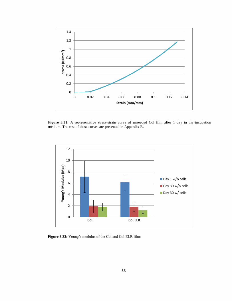
53
Figure 3.32: Young’s modulus of the Col and Col:ELR films
0
2
4
6
8
10
12
Yo
un
g's
Mo
du
lus
(Mp
a)
Col Col:ELR
Day 1 w/o cells
Day 30 w/o cells
Day 30 w/ cells
Figure 3.31: A representative stress-strain curve of unseeded Col film after 1 day in the incubation
medium. The rest of these curves are presented in Appendix B.
0
0.2
0.4
0.6
0.8
1
1.2
1.4
0 0.02 0.04 0.06 0.08 0.1 0.12 0.14
Stre
ss (
N/m
m2 )
Strain (mm/mm)
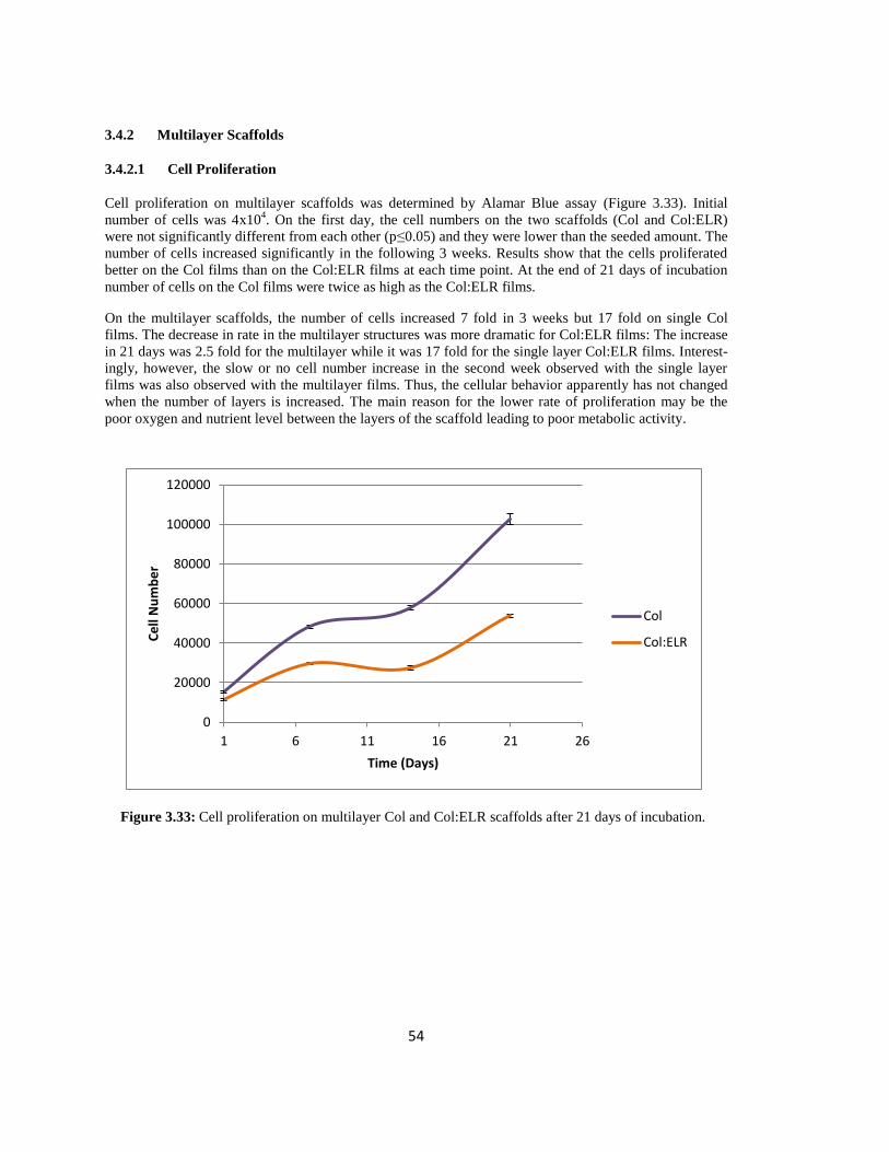
54
3.4.2 Multilayer Scaffolds
3.4.2.1 Cell Proliferation
Cell proliferation on multilayer scaffolds was determined by Alamar Blue assay (Figure 3.33). Initial
number of cells was 4x10⁴. On the first day, the cell numbers on the two scaffolds (Col and Col:ELR)
were not significantly different from each other (p≤0.05) and they were lower than the seeded amount. The
number of cells increased significantly in the following 3 weeks. Results show that the cells proliferated
better on the Col films than on the Col:ELR films at each time point. At the end of 21 days of incubation
number of cells on the Col films were twice as high as the Col:ELR films.
On the multilayer scaffolds, the number of cells increased 7 fold in 3 weeks but 17 fold on single Col
films. The decrease in rate in the multilayer structures was more dramatic for Col:ELR films: The increase
in 21 days was 2.5 fold for the multilayer while it was 17 fold for the single layer Col:ELR films. Interest-
ingly, however, the slow or no cell number increase in the second week observed with the single layer
films was also observed with the multilayer films. Thus, the cellular behavior apparently has not changed
when the number of layers is increased. The main reason for the lower rate of proliferation may be the
poor oxygen and nutrient level between the layers of the scaffold leading to poor metabolic activity.
Figure 3.33: Cell proliferation on multilayer Col and Col:ELR scaffolds after 21 days of incubation.
0
20000
40000
60000
80000
100000
120000
1 6 11 16 21 26
Ce
ll N
um
be
r
Time (Days)
Col
Col:ELR
55
3.4.2.2 Confocal Laser Scanning Microscopy (CLSM)
3.4.2.2.1 Immunostaining
3.4.2.2.1.1 Collagen Type I Staining
Structure of the cornea is predominantly composed of collagen type I and its turnover is done by the
keratocytes. Thus, in order to study the effects of the patterns and multilayer construct on the collagen type
I deposition, immunostaining was done against human collagen type I after 10 days in the culture medium
(Figure 3.34). Since the collagen is autofluorescent at almost every wavelength studied, it was difficult to
obtain a signal for collagen type I from multilayer construct using CLSM. Also, penetration of the dyes
into the layers of the construct was not homogenous. For this reason, the layers were separated and then
immunostaining was carried out. To stain the deposited collagen Alexafluor488 labeled anti-mouse Ig
antibody was used and was represented in green in the figures. As a control for the autofluorescence the
signals coming from green and red region were overlaid where the regions with total overlap were seen in
yellow and collagen deposited regions in green. Results show that after 10 days of incubation no distinct
green regions were observed as was the case with the unseeded control samples indicating that the cells
did not synthesize collagen Type I during this time period. Vrana et al. (2007b) conducted a similar study
by using collagen patterned films and they had observed collagen type I deposition after 7 days. In another
study, Builles et al. (2007) developed a hemicornea (epithelized stroma) from Collagen-GAG-Chitosan
substrates and showed that after 5 weeks of culture their construct had newly synthesized collagen type I.
The main reason for the constructs used in this study not to secrete collagen type I could be due to the lack
of oxygen between the layers of the construct which might have led to apoptosis of the cells. This also can
explain the lower cell number observed with the multilayer constructs. Also, the relatively short incubation
time may have prevented the collagen type I deposition. Cell seeding with higher density, culturing for
longer periods and using bioreactors for proper oxygen transport can enhance collagen type I deposition
and proliferation of the cells.

56
A B
C D
Figure 3.34: CSLM Images of Collagen Type I immunostaining after 10 days. A) Control, B) cross section of
the control, C) top layer of the Col multilayer construct, and D) cross section of the top layer. Scale bars: 250
µm

57
3.4.2.2.1.2 Keratan Sulfate Staining
Keratocytes are characterized by their expression of various GAGs including keratan sulfate and it is a
good indication for the preservation of keratocyte phenotype. Keratan sulfate deposition was examined by
immunostaining of the layers of the multilayer constructs on Day 10 (Figure 3.35). If there is deposited
keratan sulfate, it is presented in green color since Alexafluor488 labeled anti-mouse Ig antibody was
used. Since collagen has autofluorescence at every wavelength of the range in question an overlay of the
background and the dyes was done. Distinctive green color (which means no overlapped regions)
indicated the presence of keratan sulfate deposition. The layers of the multilayer construct were stained
separately like in Collagen type I staining. CSLM images showed no distinct green coloring in the cell
seeded constructs like in the control samples. This indicates that either the cells did not secrete any keratan
sulfate during the 10 days of culture or they lost their keratocyte phenotype. Normally keratocytes express
GAG like keratan sulfate but when their phenotype is changed into repair type they start the repair process
by secreting collagens, type I and type III, biglycan, and fibronectin (Funderburgh et al., 2003). However,
in this study the immunostaining against human collagen type I also did show any secretion of collagen
type I. Apperantly, the 10 days of culture and the number of cells seeded may not be enough for the
secretion of keratan sulfate.
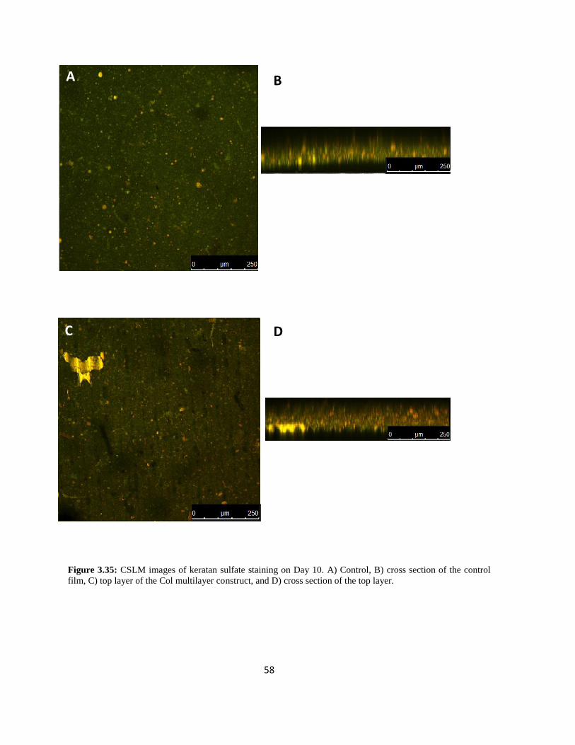
58
A
C
B
D
Figure 3.35: CSLM images of keratan sulfate staining on Day 10. A) Control, B) cross section of the control
film, C) top layer of the Col multilayer construct, and D) cross section of the top layer.

59
CHAPTER 4
CONCLUSION AND FUTURE STUDIES
Corneal diseases and injuries are the second most common causes after cataract that leads to cor-
neal blindness. Transplantation and keratoprostheses are the only options for the failed corneas but due to
drawbacks of these treatments tissue engineering field has emerged in the last few decades with the aim to
restore the function of the damaged tissues by using scaffold and the cells of the patient.
In this study a 3D scaffold was constructed from Col and Col:ELR patterned films that attempt to
mimic the natural structure and organization of the corneal stroma.
The Col and Col:ELR films and constructs were shown to support cell attachment and prolifera-
tion. Alignment of the cells on the patterned films was achieved even after 1 day of incubation and their
transparency was increased significantly over a 30 day period. The constructs appear to have the potential
for use as a stroma equivalent and their performance should be enhanced before in vivo studies. ELR
amount in the structure needs to be increased or optimized in order to show its effect more distinctly. The
seeded cell number also needs to be increased to achieve better results. The ECM secretion has to be
shown microscopically and quantified if possible. The layers can be stacked on top of each other by using
bioadhesives. Bioreactors should be used to achieve better culture conditions for tissue formation and then
the samples should be tested in vivo on rabbits by using rabbit corneal keratocytes before attempting
clinical trials.
60
REFERENCES
Al-Kharashi, S. A., Al-Obailan, M. M., Almohaimeed, M., & Al-Torbak, A. A. (2009). Deep anterior
lamellar keratoplasty. Saudi Journal of Ophthalmology, 23(3–4), 203-209. doi:
10.1016/j.sjopt.2009.10.004
Amruthwar, S. S., & Janorkar, A. V.In vitro evaluation of elastin-like polypeptide–collagen composite
scaffold for bone tissue engineering. Dental Materials, (0) doi: 10.1016/j.dental.2012.10.003
Arenas, E., Esquenazi, S., Anwar, M., & Terry, M. (2012). Lamellar corneal transplantation. Survey of
Ophthalmology, 57(6), 510-529. doi: 10.1016/j.survophthal.2012.01.009
Asbell, P., & Brocks, D. (2011). Cornea overview. In D. A. Dartt, P. Bex, P. D'Amore, R. Dana, L. K.
Mcloon & J. Y. Niederkorn (Eds.), Ocular periphery and disorders (pp. 134). San Diego: Academic
Press.
Ber, S., Torun Köse, G., & Hasırcı, V. (2005). Bone tissue engineering on patterned collagen films: An in
vitro study. Biomaterials, 26(14), 1977-1986. doi: 10.1016/j.biomaterials.2004.07.007
Berglund, J. D., Mohseni, M. M., Nerem, R. M., & Sambanis, A. (2003). A biological hybrid model for
collagen-based tissue engineered vascular constructs. Biomaterials, 24(7), 1241-1254. doi:
10.1016/S0142-9612(02)00506-9
Betre, H., Chilkoti, A., & Setton, L. A. (2002). A two-step chondrocyte recovery system based on
thermally sensitive elastin-like polypeptide scaffolds for cartilage tissue engineering. Engineering in
Medicine and Biology, 2002. 24th Annual Conference and the Annual Fall Meeting of the Biomedi-
cal Engineering Society EMBS/BMES Conference, 2002. Proceedings of the Second Joint, , 1 829-
830 vol.1.
Bidwell III, G. L., Fokt, I., Priebe, W., & Raucher, D. (2007). Development of elastin-like polypeptide for
thermally targeted delivery of doxorubicin. Biochemical Pharmacology, 73(5), 620-631. doi:
10.1016/j.bcp.2006.10.028
Boccafoschi, F., Habermehl, J., Vesentini, S., & Mantovani, D. (2005). Biological performances of
collagen-based scaffolds for vascular tissue engineering. Biomaterials, 26(35), 7410-7417. doi:
10.1016/j.biomaterials.2005.05.052
Bou-Gharios, G., & de Crombrugghe, B. (2008). Chapter 15 - type I collagen structure, synthesis, and
regulation. In John P. Bilezikian A2Lawrence G. Raisz and T. John MartinA2 John P.
Bilezikian,Lawrence G.Raisz, & T. John Martin (Eds.), Principles of bone biology (third edition)
(pp. 285-318). San Diego: Academic Press. doi: 10.1016/B978-0-12-373884-4.00034-3
61
Bourne, W. M., & McLaren, J. W. (2004). Clinical responses of the corneal endothelium. Experimental
Eye Research, 78(3), 561-572. doi: 10.1016/j.exer.2003.08.002
Buerman, R. W., & Pedroza, L. (1996). Ultrastructure of the human cornea. Microscopy Research and
Technique, 33(4), 320.
Builles, N., Janin-Manificat, H., Malbouyres, M., Justin, V., Rovère, M., Pellegrini, G., Ruggiero, F.
(2010). Use of magnetically oriented orthogonal collagen scaffolds for hemi-corneal reconstruction
and regeneration. Biomaterials, 31(32), 8313-8322. doi: 10.1016/j.biomaterials.2010.07.066
Cawston, T. (1998). Matrix metalloproteinases and TIMPs: Properties and implications for the rheumatic
diseases. Molecular Medicine Today, 4(3), 130-137. doi: 10.1016/S1357-4310(97)01192-1
Chakravarti, S., Petroll, W. M., Hassell, J. R., Jester, J. V., Lass, J. H., Paul, J., & Birk, D. E. (2000).
Corneal opacity in lumican-null mice: Defects in collagen fibril structure and packing in the posteri-
or stroma. Investigative Ophthalmology & Visual Science, 41(11), 3365-3373.
Chen, H. J., Chen, H., Lai, J., Chen, C., Tsai, Y., Kuo, M., Ma, D. H. (2009). Persistence of transplanted
oral mucosal epithelial cells in human cornea. Investigative Ophthalmology & Visual Science,
50(10), 4660-4668. doi: 10.1167/iovs.09-3377
Chirila, T. V., Hicks, C. R., Dalton, P. D., Vijayasekaran, S., Lou, X., Hong, Y., Constable, I. J. (1998).
Artificial cornea. Progress in Polymer Science, 23(3), 447-473. doi: 10.1016/S0079-6700(97)00036-
1
Chirila, T. V. (2001). An overview of the development of artificial corneas with porous skirts and the use
of PHEMA for such an application. Biomaterials, 22(24), 3311-3317. doi: 10.1016/S0142-
9612(01)00168-5
Correlo, V. M., Oliveira, J. M., Mano, J. F., Neves, N. M., & Reis, R. L. (2011). Chapter 32 - natural
origin materials for bone tissue engineering – properties, processing, and performance. In Anthony
Atala, Robert Lanza, James A. Thomson and Robert M. Nerem (Eds.), Principles of regenerative
medicine (second edition) (pp. 557-586). San Diego: Academic Press. doi: 10.1016/B978-0-12-
381422-7.10032-X
Coster, J. D. (2002a). Corneal ulceration. In S. Lightman (Ed.), Fundamentals of clinical ophthalmology
(pp. 41-64). London: BMJ Publishing Group.
Coster, J. D. (2002b). Foundations of keratology. In S. Lightman (Ed.), Fundamentals of clinical ophthal-
mology (pp. 1-34). London: BMJ Publishing Group.
Crabb, R. A., & Hubel, A. (2008). Influence of matrix processing on the optical and biomechanical
properties of a corneal stroma equivalent. Tissue Engineering.Part A, 14(1), 173-182. doi:
10.1089/ten.a.2007.0139; 10.1089/ten.a.2007.0139
Curtis, A., & Wilkinson, C. (1997). Topographical control of cells. Biomaterials, 18(24), 1573-1583. doi:
10.1016/S0142-9612(97)00144-0
Dean, D., Kandel, R. P., Adhikari, H. K., & Hessel, T. (2008). Multiple chlamydiaceae species in tracho-
ma: Implications for disease pathogenesis and control. PLoS Med, 5(1), e14.

62
Engelmann, K., Böhnke, M., & Friedl, P. (1988). Isolation and long-term cultivation of human corneal
endothelial cells. Investigative Ophthalmology & Visual Science, 29(11), 1656-1662.
Engelmann, K., Bednarz, J., & Valtink, M. (2004). Prospects for endothelial transplantation. Experimental
Eye Research, 78(3), 573-578. doi: 10.1016/S0014-4835(03)00209-4
Ethier, C. R., Johnson, M., & Ruberti, J. (2004). Ocular biomechanics and biotransport. Annual Review of
Biomedical Engineering, 6(1), 249-273. doi: 10.1146/annurev.bioeng.6.040803.140055
Falconnet, D., Csucs, G., Michelle Grandin, H., & Textor, M. (2006). Surface engineering approaches to
micropattern surfaces for cell-based assays. Biomaterials, 27(16), 3044-3063. doi:
10.1016/j.biomaterials.2005.12.024
Faucheux, N., Schweiss, R., Lützow, K., Werner, C., & Groth, T. (2004). Self-assembled monolayers with
different terminating groups as model substrates for cell adhesion studies. Biomaterials, 25(14),
2721-2730. doi: 10.1016/j.biomaterials.2003.09.069
Feng, L., Li, S., Li, Y., Li, H., Zhang, L., Zhai, J., Zhu, D. (2002). Super-hydrophobic surfaces: From
natural to artificial. Advanced Materials, 14(24), 1857-1860. doi: 10.1002/adma.200290020
Fini, M. E. (1999). Keratocyte and fibroblast phenotypes in the repairing cornea. Progress in Retinal and
Eye Research, 18(4), 529-551. doi: 10.1016/S1350-9462(98)00033-0
Fittkau, M. H., Zilla, P., Bezuidenhout, D., Lutolf, M. P., Human, P., Hubbell, J. A., & Davies, N. (2005).
The selective modulation of endothelial cell mobility on RGD peptide containing surfaces by YIGSR
peptides. Biomaterials, 26(2), 167-174. doi: 10.1016/j.biomaterials.2004.02.012
Foster, A., & Gilbert, C. (1992). Epidemiology of childhood blindness. Eye (London, England), 6(2), 173-
176.
Fullwood, N. J. (2004). Collagen fibril orientation and corneal curvature. Structure, 12(2), 169-170. doi:
10.1016/j.str.2004.01.019
Funderburgh, J. L., Mann, M. M., & Funderburgh, M. L. (2003). Keratocyte phenotype mediates proteo-
glycan structure: A Role for Fibroblasts in Corneal Fibrosis. Journal of Biological Chemistry,
278(46), 45629-45637. doi: 10.1074/jbc.M303292200
Germain, L., Carrier, P., Auger, F. A., Salesse, C., & Guérin, S. L. (2000). Can we produce a human
corneal equivalent by tissue engineering? Progress in Retinal and Eye Research, 19(5), 497-527.
doi: 10.1016/S1350-9462(00)00005-7
Gil, E. S., Mandal, B. B., Park, S., Marchant, J. K., Omenetto, F. G., & Kaplan, D. L. (2010). Helicoidal
multi-lamellar features of RGD-functionalized silk biomaterials for corneal tissue engineering. Bio-
materials, 31(34), 8953-8963. doi: 10.1016/j.biomaterials.2010.08.017
Girotti, A., Reguera, J., RodrÃguez-Cabello, J., Arias, F., Alonso, M., & Testera, A. (2004). Design and
bioproduction of a recombinant multi(bio)functional elastin-like protein polymer containing cell ad-
hesion sequences for tissue engineering purposes. Journal of Materials Science: Materials in
Medicine, 15(4), 479-484. doi: 10.1023/B:JMSM.0000021124.58688.7a
63
Gomaa, A., Comyn, O., & Liu, C. (2010). Keratoprostheses in clinical practice: A review. Clinical &
Experimental Ophthalmology, 38(2), 211-224. doi: 10.1111/j.1442-9071.2010.02231.x
Griffith, L. G., & Naughton, G. (2002). Tissue engineering--current challenges and expanding opportuni-
ties. Science, 295(5557), 1009-1014. doi: 10.1126/science.1069210
Griffith, M., Jackson, W. B., Lagali, N., Merrett, K., Li, F., & Fagerholm, P. (2009). Artificial corneas: A
regenerative medicine approach. Eye (London, England), 23(10), 1985-1989.
Griffith, M., Fagerholm, P., Lagali, N., Latorre, M. A., Hackett, J., & Sheardown, H. (2011). Chapter 49 -
regenerative medicine in the cornea. In Anthony Atala, Robert Lanza, James A. Thomson and Robert
M. Nerem (Eds.), Principles of regenerative medicine (second edition) (pp. 911-924). San Diego:
Academic Press. doi: 10.1016/B978-0-12-381422-7.10049-5
Güell, J. L., Arcos, E., Gris, O., Aristizabal, D., Pacheco, M., Sanchez, C. L., & Manero, F. (2011).
Outcomes with the boston type 1 keratoprosthesis at instituto de microcirugía ocular IMO. Saudi
Journal of Ophthalmology, 25(3), 281-284. doi: 10.1016/j.sjopt.2011.04.010
Gunatillake, P. A., & Adhikari, R. (2003). Biodegradable synthetic polymers for tissue engineering.
European Cells & Materials, 5, 1-16; discussion 16.
Guo, X., Hutcheon, A. E. K., Melotti, S. A., Zieske, J. D., Trinkaus-Randall, V., & Ruberti, J. W. (2007).
Morphologic characterization of organized extracellular matrix deposition by ascorbic Acid–
Stimulated human corneal fibroblasts. Investigative Ophthalmology & Visual Science, 48(9), 4050-
4060. doi: 10.1167/iovs.06-1216
Hafemann, B., Ensslen, S., Erdmann, C., Niedballa, R., Zühlke, A., Ghofrani, K., & Kirkpatrick, C. J.
(1999). Use of a collagen/elastin-membrane for the tissue engineering of dermis. Burns, 25(5), 373-
384. doi: 10.1016/S0305-4179(98)00162-4
Hao, J., Nagano, T., Nakamura, M., Kumagai, N., Mishima, H., & Nishida, T. (1999). Galardin inhibits
collagen degradation by rabbit keratocytes by inhibiting the activation of pro-matrix metalloprotein-
ases. Experimental Eye Research, 68(5), 565-572. doi: 10.1006/exer.1998.0637
Hasırcı, V., Lewandrowski, K., Gresser, J. D., Wise, D. L., & Trantolo, D. J. (2001). Versatility of
biodegradable biopolymers: Degradability and an in vivo application. Journal of Biotechnology,
86(2), 135-150. doi: 10.1016/S0168-1656(00)00409-0
Hasirci, V., & Kenar, H. (2006). Novel surface patterning approaches for tissue engineering and their
effect on cell behavior. Nanomedicine (London, England), 1(1), 73-90.
Hicks, C. R., Crawford, G. J., Dart, J. K. G., Grabner, G., Holland, E. J., Stulting, R. D., Bulsara, M.
(2006). AlphaCor: Clinical outcomes. Cornea, 25(9), 1034-1042
10.1097/01.ico.0000229982.23334.6b.
Hu, X., Lui, W., Cui, L., Wang, M., & Cao, Y. (2005). Tissue engineering of nearly transparent corneal
stroma. Tissue Engineering, 11(11-12), 1710-1717. doi: 10.1089/ten.2005.11.1710

64
Isenberg, S., Rutar, T., Lietman, T., Nischal, K., Wilson, E., Murray, T., Traboulsi, E. (2009). 138:
International childhood blindness. Journal of American Association for Pediatric Ophthalmology
and Strabismus, 13(1), e34. doi: 10.1016/j.jaapos.2008.12.140
Janorkar, A. V., Rajagopalan, P., Yarmush, M. L., & Megeed, Z. (2008). The use of elastin-like polypep-
tide–polyelectrolyte complexes to control hepatocyte morphology and function in vitro.
Biomaterials, 29(6), 625-632. doi: 10.1016/j.biomaterials.2007.10.022
Jester, J. V. (2008). Corneal crystallins and the development of cellular transparency. Seminars in Cell &
Developmental Biology, 19(2), 82-93. doi: 10.1016/j.semcdb.2007.09.015
Jester, J. V., Moller-Pedersen, T., Huang, J., Sax, C. M., Kays, W. T., Cavangh, H. D., Piatigorsky, J.
(1999). The cellular basis of corneal transparency: Evidence for 'corneal crystallins'. Journal of Cell
Science, 112 ( Pt 5)(Pt 5), 613-622.
Jiang, T. S., Cai, L., Ji, W. Y., Hui, Y. N., Wang, Y. S., Hu, D., & Zhu, J. (2010). Reconstruction of the
corneal epithelium with induced marrow mesenchymal stem cells in rats. Molecular Vision, 16,
1304-1316.
Joyce, N. C. (2003). Proliferative capacity of the corneal endothelium. Progress in Retinal and Eye
Research, 22(3), 359-389. doi: 10.1016/S1350-9462(02)00065-4
Kaji, Y. (2002). Anatomy of the cornea, limbus and sclera. In D. J. Apple, L. Buratto, J. L. Alio, S. K.
Pandey & A. Agarwal (Eds.), Textbook of ophthalmology. New Delhi: Jaypee.
Kenar, H., Köse, G. T., & Hasirci, V. (2006). Tissue engineering of bone on micropatterned biodegradable
polyester films. Biomaterials, 27(6), 885-895. doi: 10.1016/j.biomaterials.2005.07.001
Kenar, H., Kose, G. T., Toner, M., Kaplan, D. L., & Hasirci, V. (2011). A 3D aligned microfibrous
myocardial tissue construct cultured under transient perfusion. Biomaterials, 32(23), 5320-5329. doi:
10.1016/j.biomaterials.2011.04.025
Kinikoglu, B., Rodriguez-Cabello, J. C., Damour, O., & Hasirci, V. (2011a). A smart bilayer scaffold of
elastin-like recombinamer and collagen for soft tissue engineering. Journal of Materials Sci-
ence.Materials in Medicine, 22(6), 1541-1554. doi: 10.1007/s10856-011-4315-6
Kinikoglu, B., Rodríguez-Cabello, J. C., Damour, O., & Hasirci, V. (2011b). The influence of elastin-like
recombinant polymer on the self-renewing potential of a 3D tissue equivalent derived from human
lamina propria fibroblasts and oral epithelial cells. Biomaterials, 32(25), 5756-5764. doi:
10.1016/j.biomaterials.2011.04.054
Kojima, C., Suehiro, T., Watanabe, K., Ogawa, M., Fukuhara, A., Nishisaka, E., Magata, Y. (2012).
Doxorubicin-conjugated dendrimer/collagen hybrid gels for metastasis-associated drug delivery sys-
tems. Acta Biomaterialia, (0) doi: 10.1016/j.actbio.2012.11.013
Köse, G. T., Korkusuz, F., Korkusuz, P., Purali, N., Özkul, A., & Hasırcı, V. (2003). Bone generation on
PHBV matrices: An in vitro study. Biomaterials, 24(27), 4999-5007. doi: 10.1016/S0142-
9612(03)00417-4
65
Köse, G. T., Korkusuz, F., Özkul, A., Soysal, Y., Özdemir, T., Yildiz, C., & Hasirci, V. (2005). Tissue
engineered cartilage on collagen and PHBV matrices. Biomaterials, 26(25), 5187-5197. doi:
10.1016/j.biomaterials.2005.01.037
Laattala, K., Huhtinen, R., Puska, M., Arstila, H., Hupa, L., Kellomäki, M., & Vallittu, P. K. (2011).
Bioactive composite for keratoprosthesis skirt. Journal of the Mechanical Behavior of Biomedical
Materials, 4(8), 1700-1708. doi: 10.1016/j.jmbbm.2011.05.025
Langer, R., & Vacanti, J. (1993). Tissue engineering. Science, 260(5110), 920-926. doi:
10.1126/science.8493529
Last, J. A., Liliensiek, S. J., Nealey, P. F., & Murphy, C. J. (2009). Determining the mechanical properties
of human corneal basement membranes with atomic force microscopy. Journal of Structural Biolo-
gy, 167(1), 19-24. doi: 10.1016/j.jsb.2009.03.012
Lawrence, B. D., Marchant, J. K., Pindrus, M. A., Omenetto, F. G., & Kaplan, D. L. (2009). Silk film
biomaterials for cornea tissue engineering. Biomaterials, 30(7), 1299-1308. doi:
10.1016/j.biomaterials.2008.11.018
Liu, C., Paul, B., Tandon, R., Lee, E., Fong, K., Mavrikakis, I., Hamada, S. (2005). The osteo-odonto-
keratoprosthesis (OOKP). Semin Ophthalmol, 20(2), 113-128. doi: 10.1080/08820530590931386
Liu, C., Xia, Z., & Czernuszka, J. T. (2007). Design and development of three-dimensional scaffolds for
tissue engineering. Chemical Engineering Research and Design, 85(7), 1051-1064. doi:
10.1205/cherd06196
Liu, Y., Ma, L., & Gao, C. (2012). Facile fabrication of the glutaraldehyde cross-linked collagen/chitosan
porous scaffold for skin tissue engineering. Materials Science and Engineering: C, 32(8), 2361-
2366. doi: 10.1016/j.msec.2012.07.008
Liu, Y., Ren, L., & Wang, Y. (2013). Crosslinked collagen–gelatin–hyaluronic acid biomimetic film for
cornea tissue engineering applications. Materials Science and Engineering: C, 33(1), 196-201. doi:
10.1016/j.msec.2012.08.030
Liu, Z., Huang, A. J., & Pflugfelder, S. C. (1999). Evaluation of corneal thickness and topography in
normal eyes using the orbscan corneal topography system. The British Journal of Ophthalmology,
83(7), 774-778.
Ma, L., Gao, C., Mao, Z., Zhou, J., Shen, J., Hu, X., & Han, C. (2003). Collagen/chitosan porous scaffolds
with improved biostability for skin tissue engineering. Biomaterials, 24(26), 4833-4841. doi:
10.1016/S0142-9612(03)00374-0
Martínez-Osorio, H., Juárez-Campo, M., Diebold, Y., Girotti, A., Alonso, M., Arias, F. J., Calonge, M.
(2009). Genetically engineered elastin-like polymer as a substratum to culture cells from the ocular
surface. Curr Eye Res, 34(1), 48-56. doi: 10.1080/02713680802542053
Maurice, D. M. (1957). The structure and transparency of the cornea. The Journal of Physiology, 136(2),
263-286.
66
McLaughlin, C. R., Osborne, R., Hyatt, A., Watsky, M. A., Dare, E. V., Jarrold, B. B., Griffith, M.
(2009). Tissue engineered models for in vitro studies. In U. Meyer, J. Handschel, H. P. Wiesmann &
T. Meyer (Eds.), Fundamentals of tissue engineering and regenerative medicine (1st ed., ). New
York: Verlag Berlin Heidelberg.
McLaughlin, C. R., Acosta, M. C., Luna, C., Liu, W., Belmonte, C., Griffith, M., & Gallar, J. (2010).
Regeneration of functional nerves within full thickness collagen–phosphorylcholine corneal substi-
tute implants in guinea pigs. Biomaterials, 31(10), 2770-2778. doi:
10.1016/j.biomaterials.2009.12.031
Meek, K. M., & Leonard, D. W. (1993). Ultrastructure of the corneal stroma: A comparative study.
Biophysical Journal, 64(1), 273-280. doi: 10.1016/S0006-3495(93)81364-X
Meek, K. M., & Fullwood, N. J. (2001). Corneal and scleral collagens—a microscopist’s perspective.
Micron, 32(3), 261-272. doi: 10.1016/S0968-4328(00)00041-X
Meek, K. M., Leonard, D. W., Connon, C. J., Dennis, S., & Khan, S. (2003). Transparency, swelling and
scarring in the corneal stroma. Eye (London, England), 17(8), 927-936.
Meek, K. M., & Boote, C. (2004). The organization of collagen in the corneal stroma. Experimental Eye
Research, 78(3), 503-512. doi: 10.1016/j.exer.2003.07.003
Meek, K. (2009). Corneal collagen-"its role in maintaining corneal shape and transparency". Biophysical
Reviews, 1(2), 83-93. doi: 10.1007/s12551-009-0011-x
Menzies, K.,L., & Jones, L. (2010). The impact of contact angle on the biocompatibility of biomaterials.
Optometry and Vision Science, , 1.
Merrett, K., Liu, W., Mitra, D., Camm, K. D., McLaughlin, C. R., Liu, Y., Fogg, D. E. (2009). Synthetic
neoglycopolymer-recombinant human collagen hybrids as biomimetic crosslinking agents in corneal
tissue engineering. Biomaterials, 30(29), 5403-5408. doi: 10.1016/j.biomaterials.2009.06.016
Muraine, M., Toubeau, D., Menguy, E., & Brasseur, G. (2002). Analysing the various obstacles to cornea
postmortem procurement. The British Journal of Ophthalmology, 86(8), 864-868.
Murphy, C. M., Haugh, M. G., & O'Brien, F. J. (2010). The effect of mean pore size on cell attachment,
proliferation and migration in collagen–glycosaminoglycan scaffolds for bone tissue engineering.
Biomaterials, 31(3), 461-466. doi: 10.1016/j.biomaterials.2009.09.063
Muthusubramaniam, L., Peng, L., Zaitseva, T., Paukshto, M., Martin, G. R., & Desai, T. A. (2012).
Collagen fibril diameter and alignment promote the quiescent keratocyte phenotype. Journal of Bio-
medical Materials Research Part A, 100 A(3), 613-621. doi: 10.1002/jbm.a.33284
Myung, D., Duhamel, P. E., Cochran, J. R., Noolandi, J., Ta, C. N., & Frank, C. W. (2008). Development
of hydrogel-based keratoprostheses: A materials perspective. Biotechnology Progress, 24(3), 735-
741. doi: 10.1021/bp070476n
Nair, L. S., & Laurencin, C. T. (2007). Biodegradable polymers as biomaterials. Progress in Polymer
Science, 32(8–9), 762-798. doi: 10.1016/j.progpolymsci.2007.05.017
67
Negrel, A. D., & Thylefors, B. (1998). The global impact of eye injuries. Ophthalmic Epidemiology, 5(3),
143-169.
Nishida, T. (2005). Cornea. In J. H. Krachmer, M. J. Mannis & E. J. Holland (Eds.), Cornea (2nd ed., ).
Philadelphia: Elsevier/Mosby.
Oliva, M. S., Schottman, T., & Gulati, M. (2012). Turning the tide of corneal blindness. Indian Journal of
Ophthalmology, 60(5), 423-427. doi: 10.4103/0301-4738.100540; 10.4103/0301-4738.100540
Olsen, D., Yang, C., Bodo, M., Chang, R., Leigh, S., Baez, J., Polarek, J. (2003). Recombinant collagen
and gelatin for drug delivery. Advanced Drug Delivery Reviews, 55(12), 1547-1567. doi:
10.1016/j.addr.2003.08.008
Ozturk, N., Girotti, A., Kose, G. T., Rodríguez-Cabello, J. C., & Hasirci, V. (2009). Dynamic cell
culturing and its application to micropatterned, elastin-like protein-modified poly(N-
isopropylacrylamide) scaffolds. Biomaterials, 30(29), 5417-5426. doi:
10.1016/j.biomaterials.2009.06.044
Pachence, J. M., Bohrer, M. P., & Kohn, J. (2007). Chapter twenty-three - biodegradable polymers. In
Robert Lanza A2Robert Langer and Joseph VacantiA2 Robert Lanza,Robert Langer, & Joseph Va-
canti (Eds.), Principles of tissue engineering (third edition) (pp. 323-339). Burlington: Academic
Press. doi: 10.1016/B978-012370615-7/50027-5
Panda, A., Vanathi, M., Kumar, A., Dash, Y., & Priya, S. (2007). Corneal graft rejection. Survey of
Ophthalmology, 52(4), 375-396. doi: 10.1016/j.survophthal.2007.04.008
Pang, Y., Wang, X., Ucuzian, A. A., Brey, E. M., Burgess, W. H., Jones, K. J., Greisler, H. P. (2010).
Local delivery of a collagen-binding FGF-1 chimera to smooth muscle cells in collagen scaffolds for
vascular tissue engineering. Biomaterials, 31(5), 878-885. doi: 10.1016/j.biomaterials.2009.10.007
Rafat, M., Li, F., Fagerholm, P., Lagali, N. S., Watsky, M. A., Munger, R., Griffith, M. (2008). PEG-
stabilized carbodiimide crosslinked collagen–chitosan hydrogels for corneal tissue engineering. Bio-
materials, 29(29), 3960-3972. doi: 10.1016/j.biomaterials.2008.06.017
Rajan, N., Habermehl, J., Cote, M., Doillon, C. J., & Mantovani, D. (2007). Preparation of ready-to-use,
storable and reconstituted type I collagen from rat tail tendon for tissue engineering applications.
Nat.Protocols, 1(6), 2753-2758.
Ribeiro, A., Arias, F. J., Reguera, J., Alonso, M., & Rodríguez-Cabello, J. C. (2009). Influence of the
amino-acid sequence on the inverse temperature transition of elastin-like polymers. Biophysical
Journal, 97(1), 312-320. doi: 10.1016/j.bpj.2009.03.030
Robert, M., & Harissi-Dagher, M. (2011). Boston type 1 keratoprosthesis: The CHUM experience.
Canadian Journal of Ophthalmology / Journal Canadien d'Ophtalmologie, 46(2), 164-168. doi:
10.3129/i10-103
Rodríguez-Cabello, J. C., Martín, L., Alonso, M., Arias, F. J., & Testera, A. M. (2009). “Recombinamers”
as advanced materials for the post-oil age. Polymer, 50(22), 5159-5169. doi:
10.1016/j.polymer.2009.08.032
68
Rossert, J., & de Crombrugghe, B. (2002). Chapter 12 - type I collagen: Structure, synthesis, and regula-
tion. In John P. Bilezikian, Lawrence G. Raisz and Gideon A. Rodan (Eds.), Principles of bone
biology (second edition) (pp. 189-XVIII). San Diego: Academic Press. doi: 10.1016/B978-
012098652-1.50114-1
Ruberti, J. W., Zieske, J. D., & Trinkaus-Randall, V. (2007). Chapter sixty-eight - corneal-tissue replace-
ment. In Robert Lanza, Robert Langer and Joseph Vacanti (Eds.), Principles of tissue engineering
(third edition) (pp. 1025-1047). Burlington: Academic Press. doi: 10.1016/B978-012370615-
7/50072-X
Ruberti, J. W., & Zieske, J. D. (2008). Prelude to corneal tissue engineering – gaining control of collagen
organization. Progress in Retinal and Eye Research, 27(5), 549-577. doi:
10.1016/j.preteyeres.2008.08.001
Ruszczak, Z., & Friess, W. (2003). Collagen as a carrier for on-site delivery of antibacterial drugs.
Advanced Drug Delivery Reviews, 55(12), 1679-1698. doi: 10.1016/j.addr.2003.08.007
Sawhney, A. S., & Drumheller, P. D. (1998). Chapter II.4 - polymer synthesis. In Charles W. Patrick, Jr.,
Antonios G. Mikos, Larry V. McIntire and R.S. Langer (Eds.), Frontiers in tissue engineering (pp.
83-106). Oxford: Pergamon. doi: 10.1016/B978-008042689-1/50007-8
Senaratne, L. S., Park, P., & Kim, S. (2006). Isolation and characterization of collagen from brown backed
toadfish (lagocephalus gloveri) skin. Bioresource Technology, 97(2), 191-197. doi:
10.1016/j.biortech.2005.02.024
Shah, A., Brugnano, J., Sun, S., Vase, A., & Orwin, E. (2008). The development of a tissue-engineered
cornea: Biomaterials and culture methods. Pediatric Research, 63(5), 535-544. doi:
10.1203/PDR.0b013e31816bdf54; 10.1203/PDR.0b013e31816bdf54
Strahlman, E., Elman, M., Daub, E., & Baker, S. (1990). Causes of pediatric eye injuries. A population-
based study. Arch Ophthalmol, 108(4), 603-606.
Su, Y., Su, Q., Liu, W., Lim, M., Venugopal, J. R., Mo, X., El-Newehy, M. (2012). Controlled release of
bone morphogenetic protein 2 and dexamethasone loaded in core–shell PLLACL–collagen fibers for
use in bone tissue engineering. Acta Biomaterialia, 8(2), 763-771. doi: 10.1016/j.actbio.2011.11.002
Subramani, K. (2010). Chapter 11 - fabrication of hydrogel micropatterns by soft photolithography. In
Waqar Ahmed, & Mark J. Jackson (Eds.), Emerging nanotechnologies for manufacturing (pp. 261-
276). Boston: William Andrew Publishing. doi: 10.1016/B978-0-8155-1583-8.00011-9
Suzuki, K., Saito, J., Yanai, R., Yamada, N., Chikama, T., Seki, K., & Nishida, T. (2003). Cell–matrix and
cell–cell interactions during corneal epithelial wound healing. Progress in Retinal and Eye Research,
22(2), 113-133. doi: 10.1016/S1350-9462(02)00042-3
Taraballi, F., Zanini, S., Lupo, C., Panseri, S., Cunha, C., Riccardi, C., Cipolla, L. (2012). Amino and
carboxyl plasma functionalization of collagen films for tissue engineering applications. Journal of
Colloid and Interface Science, doi: http://dx.doi.org/10.1016/j.jcis.2012.11.041
Teichmann, J., Valtink, M., Gramm, S., Nitschke, M., Werner, C., Funk, R. H. W., & Engelmann, K.
(2013). Human corneal endothelial cell sheets for transplantation: Thermo-responsive cell culture
69
carriers to meet cell-specific requirements. Acta Biomaterialia, 9(2), 5031-5039. doi:
10.1016/j.actbio.2012.10.023
Tian, H., Tang, Z., Zhuang, X., Chen, X., & Jing, X. (2012). Biodegradable synthetic polymers: Prepara-
tion, functionalization and biomedical application. Progress in Polymer Science, 37(2), 237-280. doi:
10.1016/j.progpolymsci.2011.06.004
Torbet, J., Malbouyres, M., Builles, N., Justin, V., Roulet, M., Damour, O., Hulmes, D. J. S. (2007).
Orthogonal scaffold of magnetically aligned collagen lamellae for corneal stroma reconstruction. Bi-
omaterials, 28(29), 4268-4276. doi: 10.1016/j.biomaterials.2007.05.024
Trinkaus-Randall, V. (2000). Cornea. In R. P. Lanza, R. Langer & J. Vacanti (Eds.), Principles of tissue
engineering (2nd ed., ). San Diego, CA: Academic Press.
Vacanti, J., & Vacanti, C. A. (2007). Chapter one - the history and scope of tissue engineering. In Robert
Lanza, Robert Langer and Joseph Vacanti (Eds.), Principles of tissue engineering (third edition) (pp.
3-6). Burlington: Academic Press. doi: 10.1016/B978-012370615-7/50005-6
Vasantha, V., Sehgal, P. K., & Rao, K. P. (1988). Collagen ophthalmic inserts for pilocarpine drug
delivery system. International Journal of Pharmaceutics, 47(1–3), 95-102. doi: 10.1016/0378-
5173(88)90219-0
Viitala, R., Franklin, V., Green, D., Liu, C., Lloyd, A., & Tighe, B. (2009). Towards a synthetic osteo-
odonto-keratoprosthesis. Acta Biomaterialia, 5(1), 438-452. doi: 10.1016/j.actbio.2008.07.008
Vrana, N. E., Builles, N., Kocak, H., Gulay, P., Justin, V., Malbouyres, M., Hasirci, V. (2007a).
EDC/NHS cross-linked collagen foams as scaffolds for artificial corneal stroma. Journal of Bio-
materials Science.Polymer Edition, 18(12), 1527-1545.
Vrana, N. E., Elsheikh, A., Builles, N., Damour, O., & Hasirci, V. (2007b). Effect of human corneal
keratocytes and retinal pigment epithelial cells on the mechanical properties of micropatterned colla-
gen films. Biomaterials, 28(29), 4303-4310. doi: 10.1016/j.biomaterials.2007.06.013
Vrana, E., Builles, N., Hindie, M., Damour, O., Aydinli, A., & Hasirci, V. (2008a). Contact guidance
enhances the quality of a tissue engineered corneal stroma. Journal of Biomedical Materials Re-
search.Part A, 84(2), 454-463. doi: 10.1002/jbm.a.31442
Vrana, N. E., Builles, N., Justin, V., Bednarz, J., Pellegrini, G., Ferrari, B., Hasirci, V. (2008b). Develop-
ment of a reconstructed cornea from Collagen–Chondroitin sulfate foams and human cell cultures.
Investigative Ophthalmology & Visual Science, 49(12), 5325-5331. doi: 10.1167/iovs.07-1599
Wang, S., Liu, W., Han, B., & Yang, L. (2009). Study on a hydroxypropyl chitosan–gelatin based scaffold
for corneal stroma tissue engineering. Applied Surface Science, 255(20), 8701-8705. doi:
10.1016/j.apsusc.2009.04.206
Weadock, K. S., Miller, E. J., Bellincampi, L. D., Zawadsky, J. P., & Dunn, M. G. (1995). Physical
crosslinking of collagen fibers: Comparison of ultraviolet irradiation and dehydrothermal treatment.
Journal of Biomedical Materials Research, 29(11), 1373-1379. doi: 10.1002/jbm.820291108
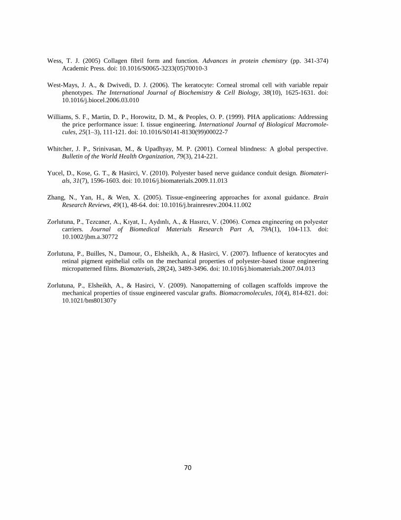
70
Wess, T. J. (2005) Collagen fibril form and function. Advances in protein chemistry (pp. 341-374)
Academic Press. doi: 10.1016/S0065-3233(05)70010-3
West-Mays, J. A., & Dwivedi, D. J. (2006). The keratocyte: Corneal stromal cell with variable repair
phenotypes. The International Journal of Biochemistry & Cell Biology, 38(10), 1625-1631. doi:
10.1016/j.biocel.2006.03.010
Williams, S. F., Martin, D. P., Horowitz, D. M., & Peoples, O. P. (1999). PHA applications: Addressing
the price performance issue: I. tissue engineering. International Journal of Biological Macromole-
cules, 25(1–3), 111-121. doi: 10.1016/S0141-8130(99)00022-7
Whitcher, J. P., Srinivasan, M., & Upadhyay, M. P. (2001). Corneal blindness: A global perspective.
Bulletin of the World Health Organization, 79(3), 214-221.
Yucel, D., Kose, G. T., & Hasirci, V. (2010). Polyester based nerve guidance conduit design. Biomateri-
als, 31(7), 1596-1603. doi: 10.1016/j.biomaterials.2009.11.013
Zhang, N., Yan, H., & Wen, X. (2005). Tissue-engineering approaches for axonal guidance. Brain
Research Reviews, 49(1), 48-64. doi: 10.1016/j.brainresrev.2004.11.002
Zorlutuna, P., Tezcaner, A., Kıyat, I., Aydınlı, A., & Hasırcı, V. (2006). Cornea engineering on polyester
carriers. Journal of Biomedical Materials Research Part A, 79A(1), 104-113. doi:
10.1002/jbm.a.30772
Zorlutuna, P., Builles, N., Damour, O., Elsheikh, A., & Hasirci, V. (2007). Influence of keratocytes and
retinal pigment epithelial cells on the mechanical properties of polyester-based tissue engineering
micropatterned films. Biomaterials, 28(24), 3489-3496. doi: 10.1016/j.biomaterials.2007.04.013
Zorlutuna, P., Elsheikh, A., & Hasirci, V. (2009). Nanopatterning of collagen scaffolds improve the
mechanical properties of tissue engineered vascular grafts. Biomacromolecules, 10(4), 814-821. doi:
10.1021/bm801307y
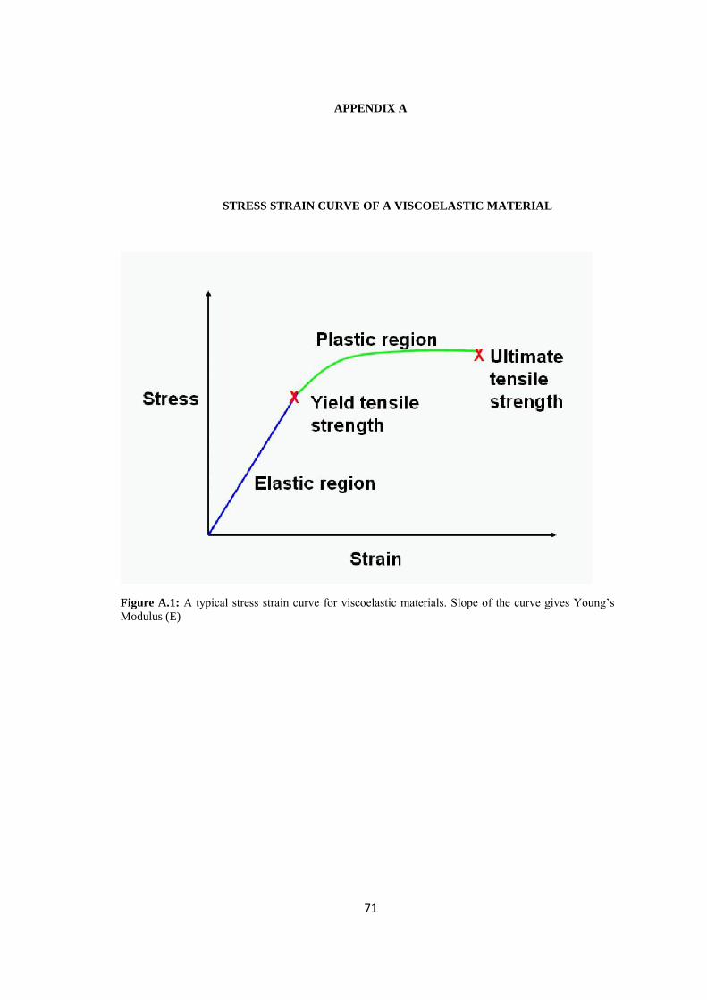
71
APPENDIX A
STRESS STRAIN CURVE OF A VISCOELASTIC MATERIAL
Figure A.1: A typical stress strain curve for viscoelastic materials. Slope of the curve gives Young’s
Modulus (E)
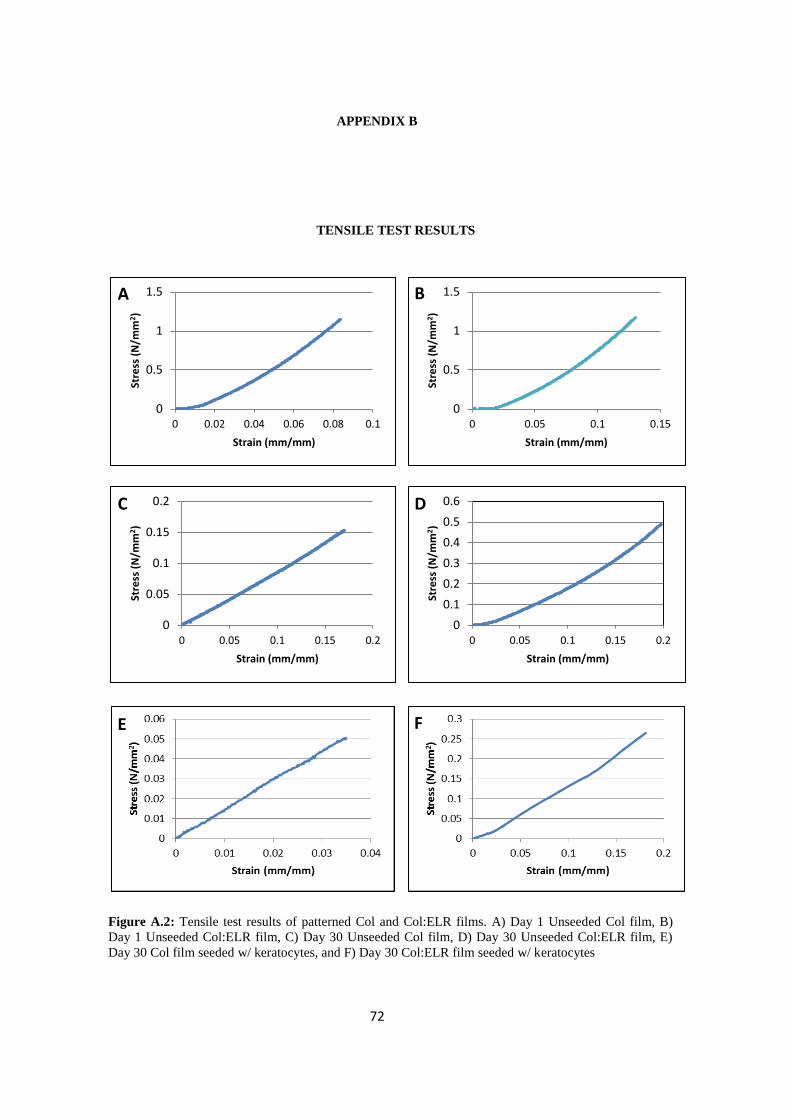
72
APPENDIX B
TENSILE TEST RESULTS
Figure A.2: Tensile test results of patterned Col and Col:ELR films. A) Day 1 Unseeded Col film, B)
Day 1 Unseeded Col:ELR film, C) Day 30 Unseeded Col film, D) Day 30 Unseeded Col:ELR film, E)
Day 30 Col film seeded w/ keratocytes, and F) Day 30 Col:ELR film seeded w/ keratocytes
E F
0
0.5
1
1.5
0 0.02 0.04 0.06 0.08 0.1
Stre
ss (
N/m
m2)
Strain (mm/mm)
0
0.5
1
1.5
0 0.05 0.1 0.15St
ress
(N
/mm
2)
Strain (mm/mm)
0
0.05
0.1
0.15
0.2
0 0.05 0.1 0.15 0.2
Stre
ss (
N/m
m2)
Strain (mm/mm)
0
0.1
0.2
0.3
0.4
0.5
0.6
0 0.05 0.1 0.15 0.2
Stre
ss (
N/m
m2)
Strain (mm/mm)
A B
C D

73
APPENDIX C
ALAMAR BLUE CALIBRATION CURVE
Figure A.3: Alamar blue assay calibration curve for human corneal keratocytes
y = 0.0818x R² = 0.9835
0
2
4
6
8
10
12
14
16
18
0 50 100 150 200 250
Pe
rce
nt
Re
du
ctio
n o
f D
ye (
%)
Cell Number (X103)
Top Related