


Languages
Pages
Legal


Structural Implications of Mounting Solar
Panels on a Residential Wood Structure
Ap
ril 3
0, 2
01
0
1
Cop
yrigh
t 2
01
0 L
ind
au
Com
pa
nie
s, In
c.
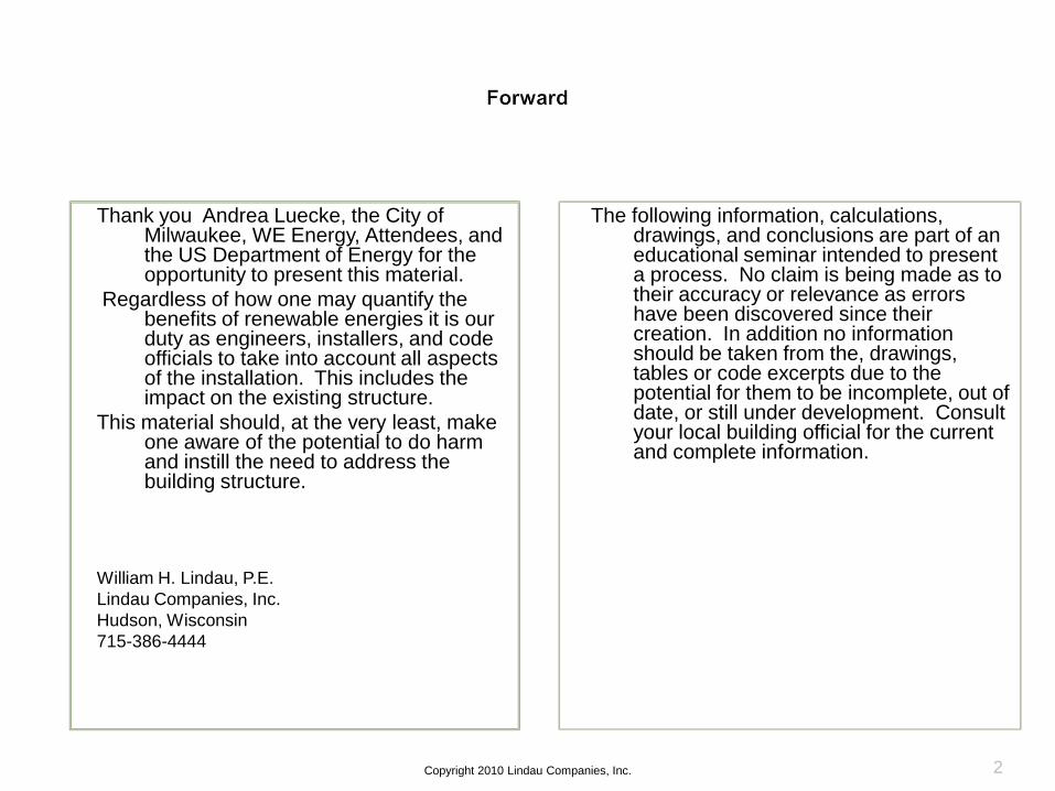
Thank you Andrea Luecke, the City of Milwaukee, WE Energy, Attendees, and the US Department of Energy for the opportunity to present this material.
Regardless of how one may quantify the benefits of renewable energies it is our duty as engineers, installers, and code officials to take into account all aspects of the installation. This includes the impact on the existing structure.
This material should, at the very least, make one aware of the potential to do harm and instill the need to address the building structure.
William H. Lindau, P.E.
Lindau Companies, Inc.
Hudson, Wisconsin
715-386-4444
The following information, calculations, drawings, and conclusions are part of an educational seminar intended to present a process. No claim is being made as to their accuracy or relevance as errors have been discovered since their creation. In addition no information should be taken from the, drawings, tables or code excerpts due to the potential for them to be incomplete, out of date, or still under development. Consult your local building official for the current and complete information.
Copyright 2010 Lindau Companies, Inc. 2

To present the process by which a structural engineer might evaluate a buildings ability to support solar hot water or photo voltaic equipment.
To provided examples of drawings and calculations that could be an important part of the permitting process.
William H. Lindau, P.E.
Lindau Companies, Inc.
Hudson, Wisconsin
715-386-4444
Limited to:
Residential structures as defined and governed by the Uniform Dwelling Code of Wisconsin Administrative Code (UDC)
Flush mounted flat solar panels
Photo Voltaic
Solar Hot Water
Wood Construction
Simple Trusses or Rafters
The calculations and drawings presented here have not been checked and could contain errors.
Copyright 2010 Lindau Companies, Inc. 3
Today’s presentation is intended to provide a
process from which a determination can be
made as to a building’s ability to support
solar equipment. This process can
incorporate many complicated mathematical
calculations and the designer should be
aware of their own, as well as their insurance
policies, limitations:
4Copyright 2010 Lindau Companies, Inc.
Based on my review and conversations with building
officials:
• Calculations may be required by a building official but they do
not need to be created by a registered professional engineer.
• UDC can be interpreted and a permit application submitted
by a contractor, designer or owner
• For all new construction, the Code must be satisfied as a
minimum
• Existing construction that does not meet the minimum ode
requirements is not required to be brought within compliance
but no increased or new loads can be imparted on it.
• Structural elements that do not conform to the Code cannot
be modified in such a way that decrease their strength.
5Copyright 2010 Lindau Companies, Inc.
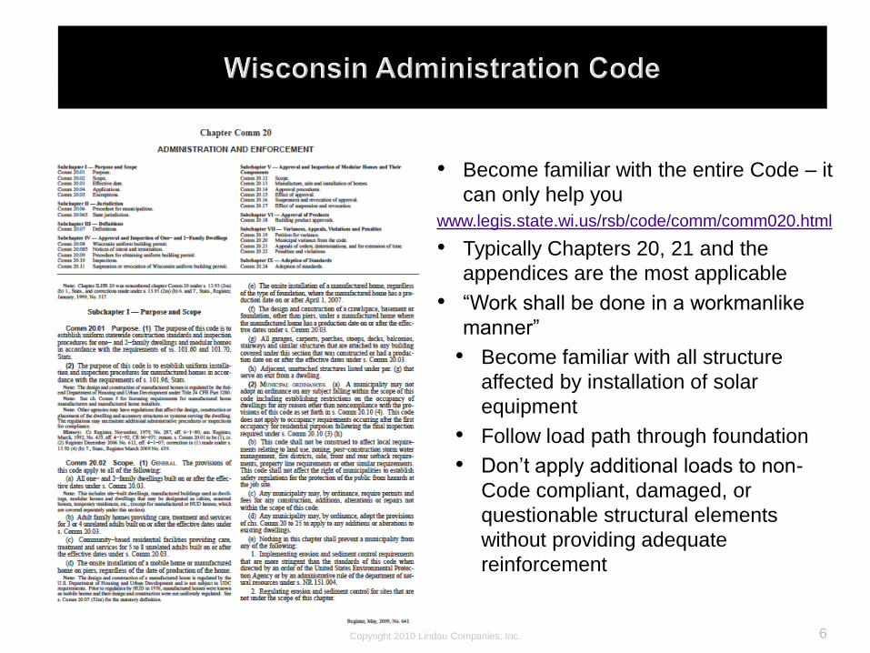
• Become familiar with the entire Code – it
can only help you
www.legis.state.wi.us/rsb/code/comm/comm020.html
• Typically Chapters 20, 21 and the
appendices are the most applicable
• “Work shall be done in a workmanlike
manner”
• Become familiar with all structure
affected by installation of solar
equipment
• Follow load path through foundation
• Don’t apply additional loads to non-
Code compliant, damaged, or
questionable structural elements
without providing adequate
reinforcement
Copyright 2010 Lindau Companies, Inc. 6

7Copyright 2010 Lindau Companies, Inc.
Uniform Dwelling Code of the
Wisconsin Administrative
Code (UDC)
• Most of the information
needed is located in
Chapter 21 and
Appendices

8Copyright 2010 Lindau Companies, Inc.
Uniform Dwelling Code of the
Wisconsin Administrative
Code (UDC)

9Copyright 2010 Lindau Companies, Inc.
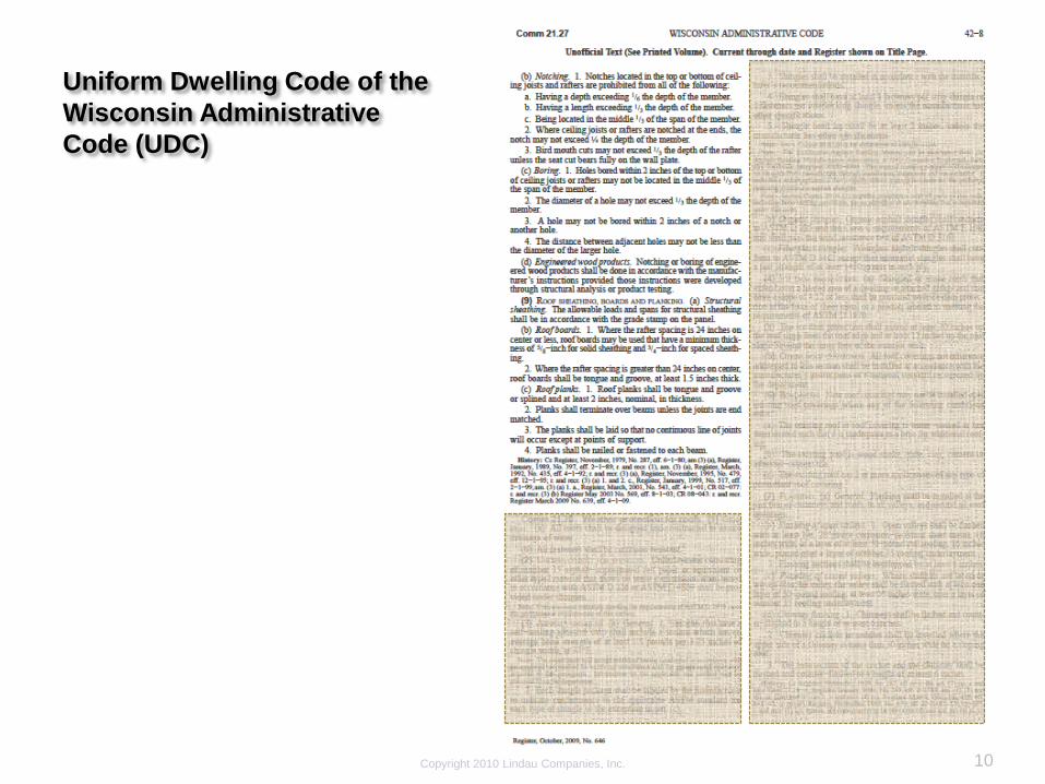
Uniform Dwelling Code of the
Wisconsin Administrative
Code (UDC)
• Snow load reduction for
roof slope
• Review all of the Code, it
can only help
10Copyright 2010 Lindau Companies, Inc.
Uniform Dwelling Code of the
Wisconsin Administrative
Code (UDC)

11
Uniform Dwelling Code of the
Wisconsin Administrative
Code (UDC)
• Note limitations of table
• Snow load reduction

12
Uniform Dwelling Code of the
Wisconsin Administrative
Code (UDC)
How to choose a table:
1) Rafter or Floor
2) Loads
3) Ceiling covering and
deflection requirements
4) Roofing weight
• “Light” roofing < 10 psf
13
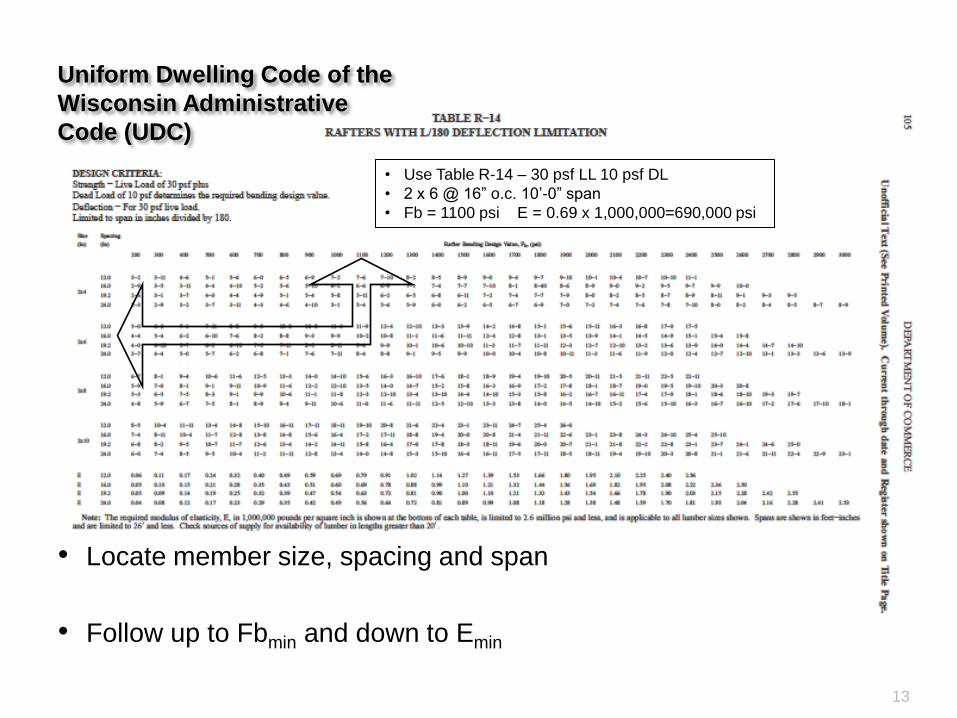
• Use Table R-14 – 30 psf LL 10 psf DL
• 2 x 6 @ 16” o.c. 10’-0” span
• Fb = 1100 psi E = 0.69 x 1,000,000=690,000 psi
Uniform Dwelling Code of the
Wisconsin Administrative
Code (UDC)
• Locate member size, spacing and span
• Follow up to Fbmin and down to Emin
14Copyright 2010 Lindau Companies, Inc.
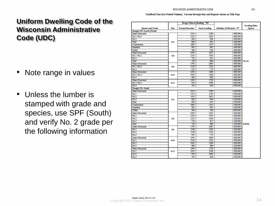
Uniform Dwelling Code of the
Wisconsin Administrative
Code (UDC)
• Note range in values
• Unless the lumber is
stamped with grade and
species, use SPF (South)
and verify No. 2 grade per
the following information

Simplified method (compare new to existing):
• Determine original design loads of an existing structure and verify conformance to the current
building code
• Determine and account for changes to roof loads due to the installation of solar equipment
• Live loads
• Snow loads
• Dead loads
• Other loads per building code
• Make comparison between the structure as originally designed and the structure after the solar
equipment has been installed.
More detailed method of evaluation:
• Perform complete structural analysis and review of all structural elements affected by the
installation and make a determination as to their adequacy
• Includes the analysis of members, their connections, bearing condition, and stability,
• Follows loads through the foundations
• Used when the simplified method cannot be performed, is not conclusive, or yields unfavorable
results and reinforcing the structure is not easily accomplished.
• Removes any doubt of adequacy and grey areas
• Usually performed by a Structural Engineer.
Only the simplified method is included in this presentation
15Copyright 2010 Lindau Companies, Inc.
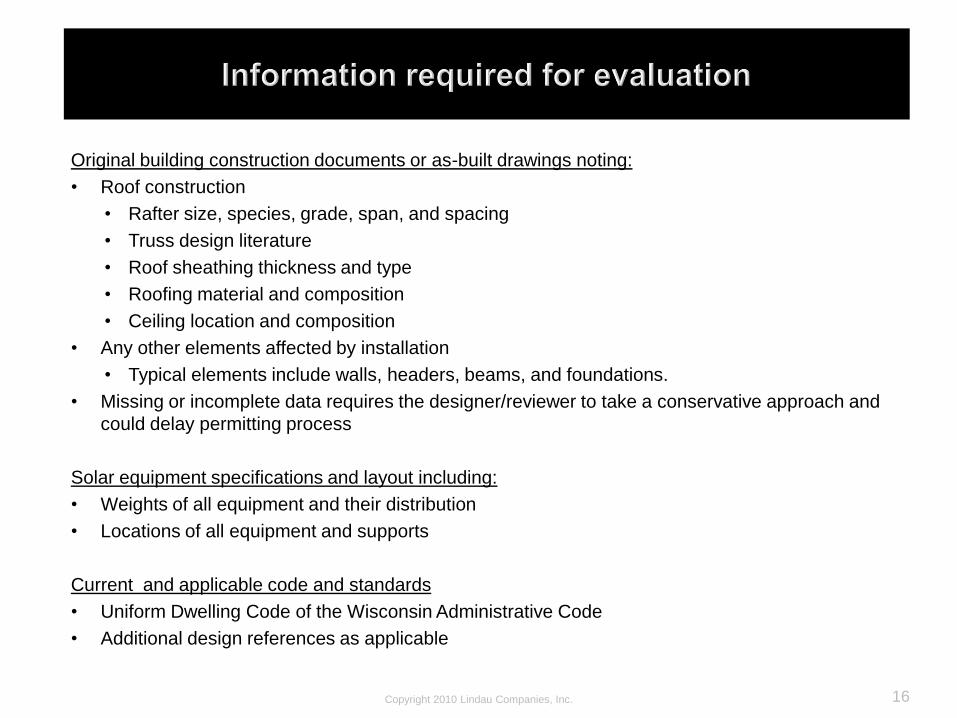
Original building construction documents or as-built drawings noting:
• Roof construction
• Rafter size, species, grade, span, and spacing
• Truss design literature
• Roof sheathing thickness and type
• Roofing material and composition
• Ceiling location and composition
• Any other elements affected by installation
• Typical elements include walls, headers, beams, and foundations.
• Missing or incomplete data requires the designer/reviewer to take a conservative approach and
could delay permitting process
Solar equipment specifications and layout including:
• Weights of all equipment and their distribution
• Locations of all equipment and supports
Current and applicable code and standards
• Uniform Dwelling Code of the Wisconsin Administrative Code
• Additional design references as applicable
16Copyright 2010 Lindau Companies, Inc.
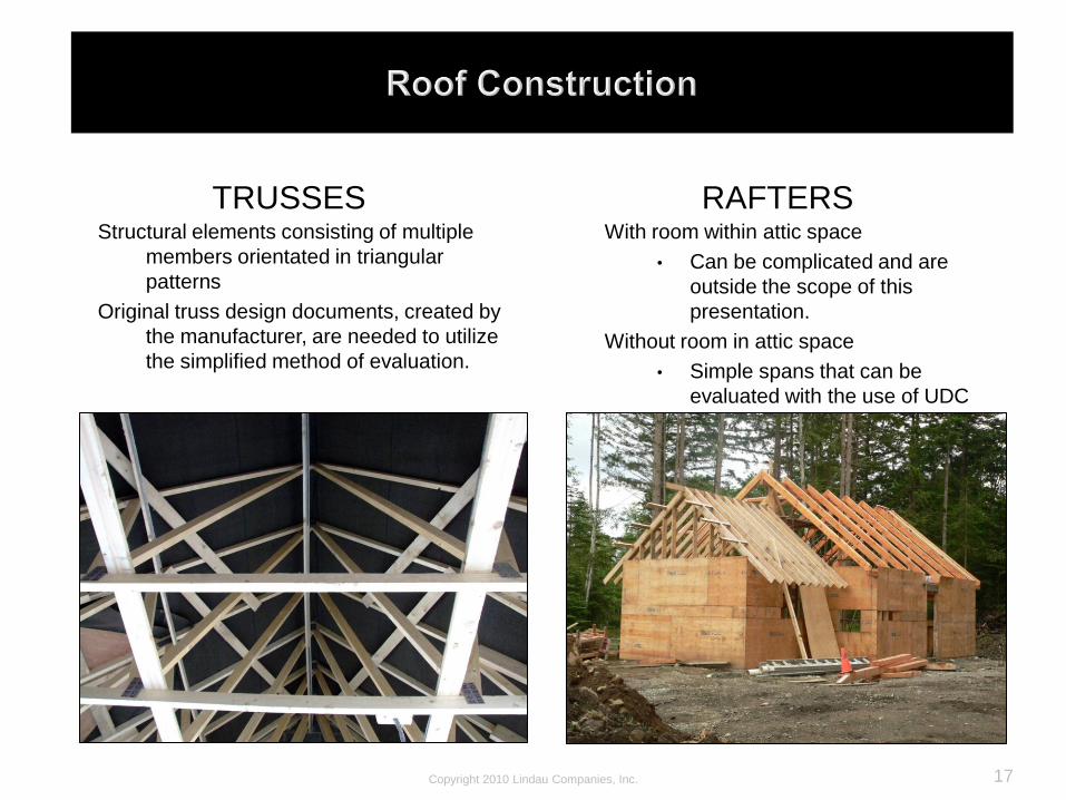
TRUSSES RAFTERSWith room within attic space
• Can be complicated and are
outside the scope of this
presentation.
Without room in attic space
• Simple spans that can be
evaluated with the use of UDC
tables.
Structural elements consisting of multiple
members orientated in triangular
patterns
Original truss design documents, created by
the manufacturer, are needed to utilize
the simplified method of evaluation.
17Copyright 2010 Lindau Companies, Inc.
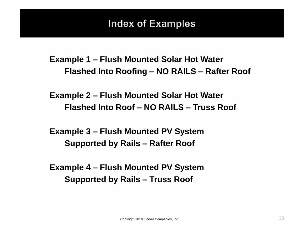
Example 1 – Flush Mounted Solar Hot Water
Flashed Into Roofing – NO RAILS – Rafter Roof
Example 2 – Flush Mounted Solar Hot Water
Flashed Into Roof – NO RAILS – Truss Roof
Example 3 – Flush Mounted PV System
Supported by Rails – Rafter Roof
Example 4 – Flush Mounted PV System
Supported by Rails – Truss Roof
18Copyright 2010 Lindau Companies, Inc.
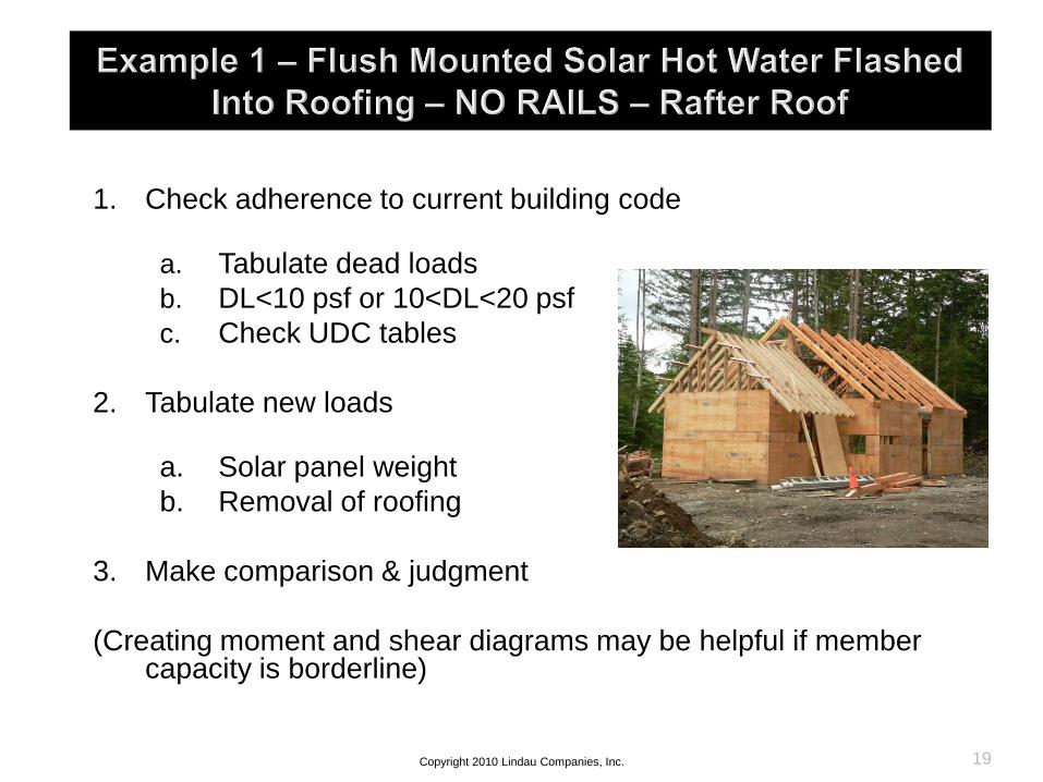
1. Check adherence to current building code
a. Tabulate dead loads
b. DL<10 psf or 10<DL<20 psf
c. Check UDC tables
2. Tabulate new loads
a. Solar panel weight
b. Removal of roofing
3. Make comparison & judgment
(Creating moment and shear diagrams may be helpful if member capacity is borderline)
19Copyright 2010 Lindau Companies, Inc.

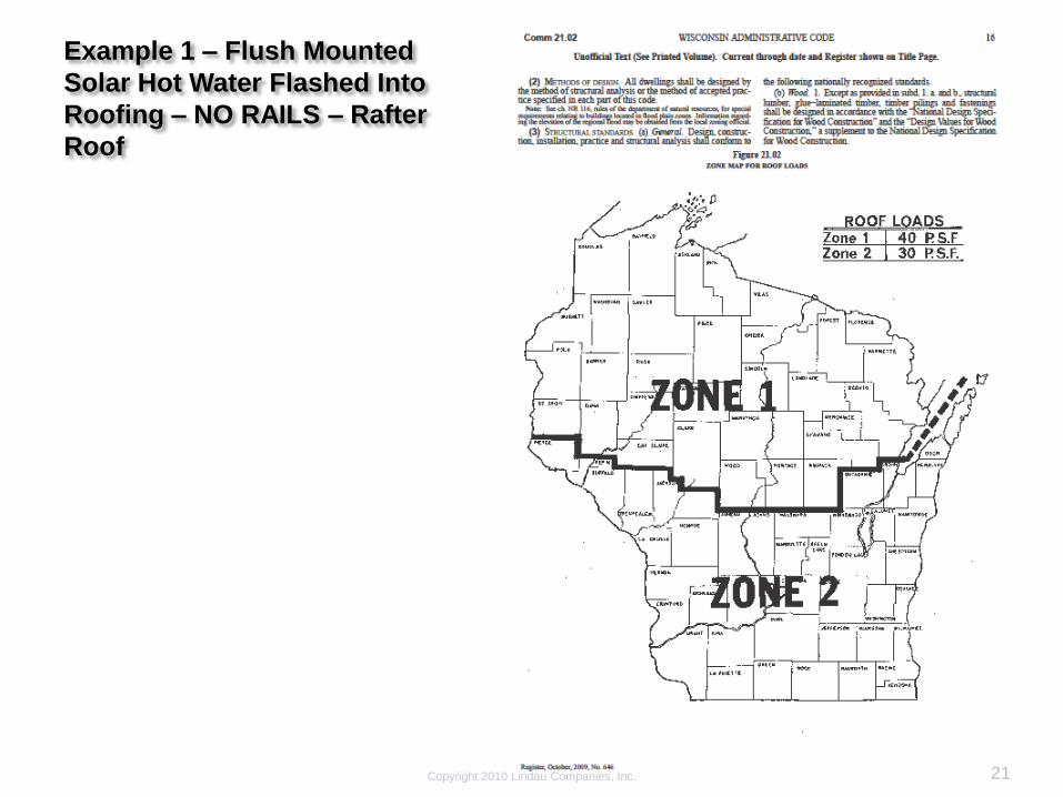
Example 1 – Flush Mounted
Solar Hot Water Flashed Into
Roofing – NO RAILS – Rafter
Roof
20
• Panels consist of (3) 72”x54”
141lb SHW bearing directly
on roof sheathing.
• Roofing material is removed
at panel
• Panel sits directly on roof
sheathing and is supported on
all sides
• Flashing is installed around
panels
Copyright 2010 Lindau Companies, Inc.
21Copyright 2010 Lindau Companies, Inc.
Example 1 – Flush Mounted
Solar Hot Water Flashed Into
Roofing – NO RAILS – Rafter
Roof

22
Example 1 – Flush Mounted
Solar Hot Water Flashed Into
Roofing – NO RAILS – Rafter
Roof
• Rafter
• Zone 2 = 30 psf
• No ceiling thus L/180
defection requirement
• “Light” roofing < 10 psf
• Table R-14

23
• Use Table R-14 – 30 psf LL 10 psf DL
• 2 x 6 @ 16” o.c. 10’-0” span
• Fb = 1100 psi E = 0.69 x 1,000,000=690,000 psi
Example 1 – Flush Mounted
Solar Hot Water Flashed Into
Roofing – NO RAILS – Rafter
Roof
• Locate member size, spacing and span
• Follow up to Fbmin and down to Emin
24Copyright 2010 Lindau Companies, Inc.
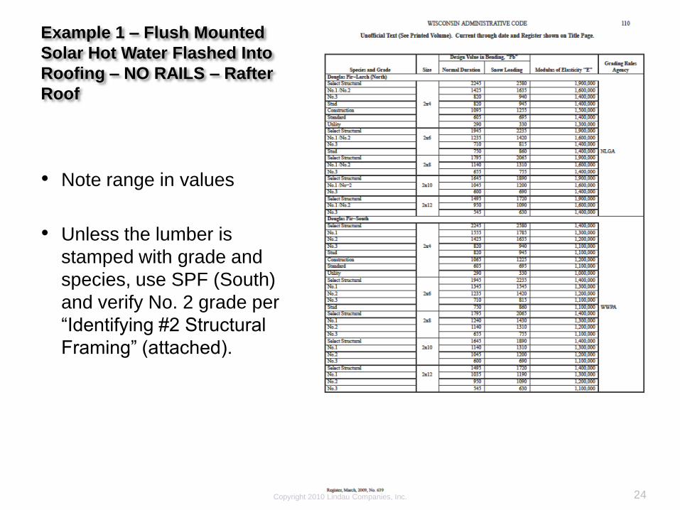
Example 1 – Flush Mounted
Solar Hot Water Flashed Into
Roofing – NO RAILS – Rafter
Roof
• Note range in values
• Unless the lumber is
stamped with grade and
species, use SPF (South)
and verify No. 2 grade per
“Identifying #2 Structural
Framing” (attached).

25Copyright 2010 Lindau Companies, Inc.
Example 1 – Flush Mounted
Solar Hot Water Flashed Into
Roofing – NO RAILS – Rafter
Roof
• Weights of building materials
should be calculated for each
job based on a thorough
examination of the building
• Exercise in unit conversion
OSB)

26Copyright 2010 Lindau Companies, Inc.
Example 1 – Flush Mounted
Solar Hot Water Flashed Into
Roofing – NO RAILS – Rafter
Roof
• Always provide manufacturer’s
product specification that
include the product weights with
the permit application

27Copyright 2010 Lindau Companies, Inc.
Example 1 – Flush Mounted
Solar Hot Water Flashed Into
Roofing – NO RAILS – Rafter
Roof
• As the panel is tilted upward,
the lbs/sq ft applied to the
horizontal projection of the roof
increases even though the
panel weight does not change
28Copyright 2010 Lindau Companies, Inc.
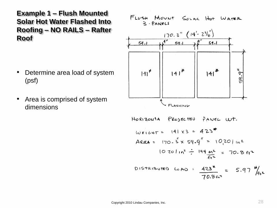
Example 1 – Flush Mounted
Solar Hot Water Flashed Into
Roofing – NO RAILS – Rafter
Roof
• Determine area load of system
(psf)
• Area is comprised of system
dimensions

29Copyright 2010 Lindau Companies, Inc.
Example 1 – Flush Mounted
Solar Hot Water Flashed Into
Roofing – NO RAILS – Rafter
Roof
• Already determined the live load
requirement is satisfied
• Verify that the dead loads (“DL”)
are not in excess of 10 psf
• If DL > 10 psf, further evaluation
utilizing shear & moment
calculation is needed

1. Determine original construction design loads
a. Manufacturer supplied calculationsb. Engineering analysisc. Original documents
2. Tabulate new loads
a. Solar panel weightb. Removal of roofing
3. Make comparison & judgment
Same process as Example 1
30
Panels
Copyright 2010 Lindau Companies, Inc.
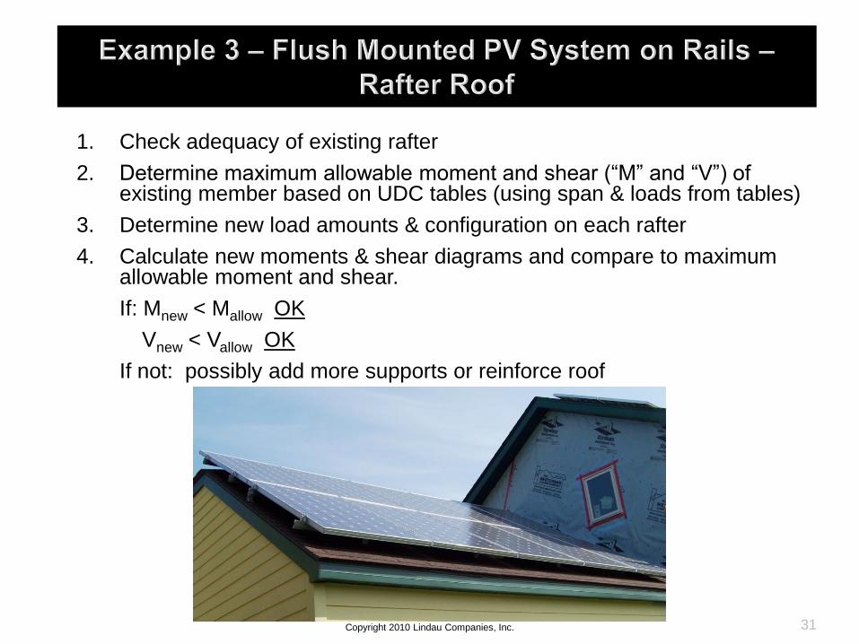
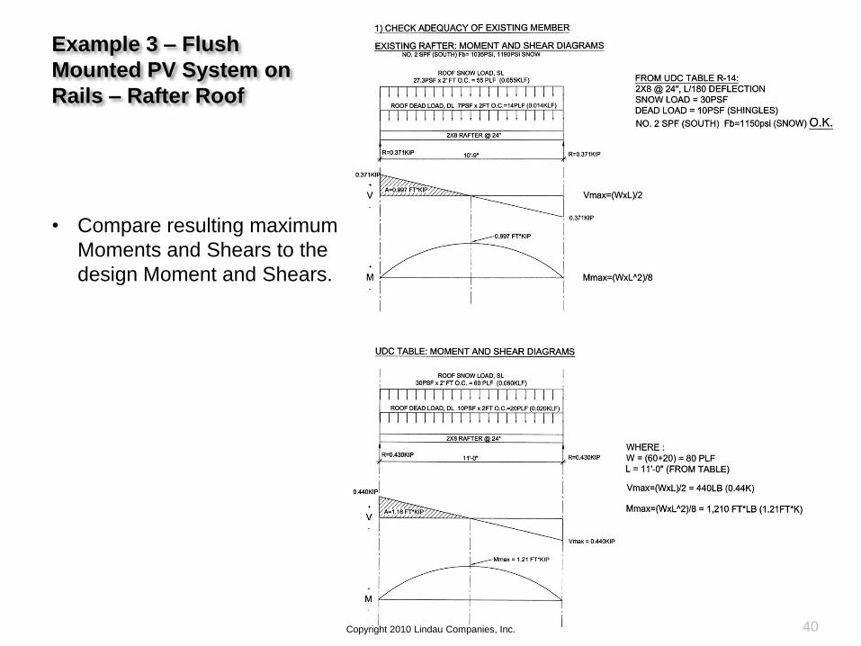
1. Check adequacy of existing rafter
2. Determine maximum allowable moment and shear (“M” and “V”) of existing member based on UDC tables (using span & loads from tables)
3. Determine new load amounts & configuration on each rafter
4. Calculate new moments & shear diagrams and compare to maximum allowable moment and shear.
If: Mnew < Mallow OK
Vnew < Vallow OK
If not: possibly add more supports or reinforce roof
31Copyright 2010 Lindau Companies, Inc.
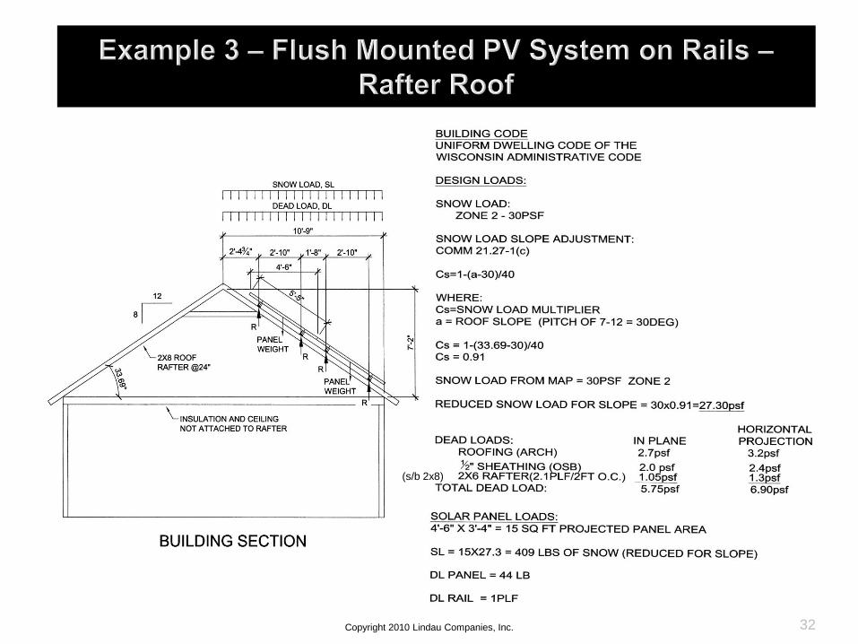
Copyright 2010 Lindau Companies, Inc. 32
(s/b 2x8)

Example 3 – Flush
Mounted PV System on
Rails – Rafter Roof
33Copyright 2010 Lindau Companies, Inc.
• Many structural design
manuals have beam
diagrams and formulas for
various static loading
conditions such as
Mmax=(WL2)/8

34Copyright 2010 Lindau Companies, Inc.
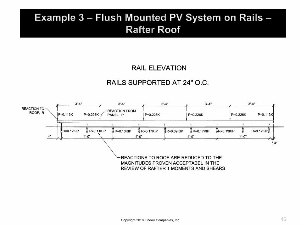
• The rail reactions shown here have been
computed by the use of analysis software
because the rail is continuous over its supports
and indeterminate to solve

35Copyright 2010 Lindau Companies, Inc.

36Copyright 2010 Lindau Companies, Inc.

37Copyright 2010 Lindau Companies, Inc.

38Copyright 2010 Lindau Companies, Inc.
• Approximate methods
include:
a. Dividing the load among
the tributary areas of its
supports
b. Treating all spans as
simple spans and using
summation of moments
and the summation of
forces in the vertical
direction to solve for the
reactions
• A conservative approach
should be taken when using
approximate methods
Example 3 – Flush
Mounted PV System on
Rails – Rafter Roof
39Copyright 2010 Lindau Companies, Inc.
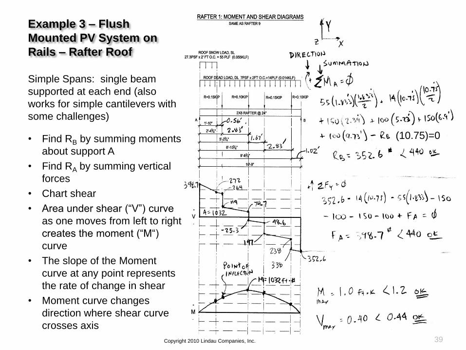
Simple Spans: single beam
supported at each end (also
works for simple cantilevers with
some challenges)
• Find RB by summing moments
about support A
• Find RA by summing vertical
forces
• Chart shear
• Area under shear (“V”) curve
as one moves from left to right
creates the moment (“M“)
curve
• The slope of the Moment
curve at any point represents
the rate of change in shear
• Moment curve changes
direction where shear curve
crosses axis
(10.75)=0
Example 3 – Flush
Mounted PV System on
Rails – Rafter Roof
40Copyright 2010 Lindau Companies, Inc.
• Compare resulting maximum
Moments and Shears to the
design Moment and Shears.

Example 3 – Flush
Mounted PV System on
Rails – Rafter Roof
41Copyright 2010 Lindau Companies, Inc.
Start the analysis with the
rafters supporting the most
load and similar members
with less load and the same
load configuration can be
evaluated by comparison

Example 3 – Flush
Mounted PV System on
Rails – Rafter Roof
42Copyright 2010 Lindau Companies, Inc.
Simple Spans: single beam
supported at each end (also
works for simple cantilevers with
some challenges)
• Find RB by summing moments
about support A
• Find RA by summing vertical
forces
• Chart shear
• Area under shear (“V”) curve
as one moves from left to right
creates the moment (“M“)
curve
• The slope of the Moment
curve at any point represents
the rate of change in shear
• Moment curve changes
direction where shear curve
crosses axis

Example 3 – Flush
Mounted PV System on
Rails – Rafter Roof
43Copyright 2010 Lindau Companies, Inc.
Simple Spans: single beam
supported at each end (also
works for simple cantilevers with
some challenges)
• Find RB by summing moments
about support A
• Find RA by summing vertical
forces
• Chart shear
• Area under shear (“V”) curve
as one moves from left to right
creates the moment (“M“)
curve
• The slope of the Moment
curve at any point represents
the rate of change in shear
(V)
• Moment curve changes
direction where shear curve
crosses axis

Example 3 – Flush
Mounted PV System on
Rails – Rafter Roof
44Copyright 2010 Lindau Companies, Inc.
Start the analysis with the
rafters supporting the most
load and similar members
with less load and the same
load configuration can be
evaluated by comparison
• Do not assume that
because the member
satisfies the moment
criteria that it will satisfy
the shear criteria

45Copyright 2010 Lindau Companies, Inc.
46Copyright 2010 Lindau Companies, Inc.
47Copyright 2010 Lindau Companies, Inc.

48Copyright 2010 Lindau Companies, Inc.

1. Determine original construction design loads
Manufacturer supplied calculations
Engineering analysis
Original documents
2. Calculate rail reactions, load configuration, and tabulate dead loads
If rail reactions fall between nodes, determine maximum moment (M) and shear (V) of members directly supporting rails OR
If rail reactions fall at nodes, determine reactions at truss nodes affected
3. Make comparison & judgment
49Copyright 2010 Lindau Companies, Inc.

Example 4 – Flush
Mounted PV System on
Rails – Truss Roof
Review of Trusses:
• Capacities are
determined through a
lengthy process
• Usually performed by a
truss supplier
50Copyright 2010 Lindau Companies, Inc.
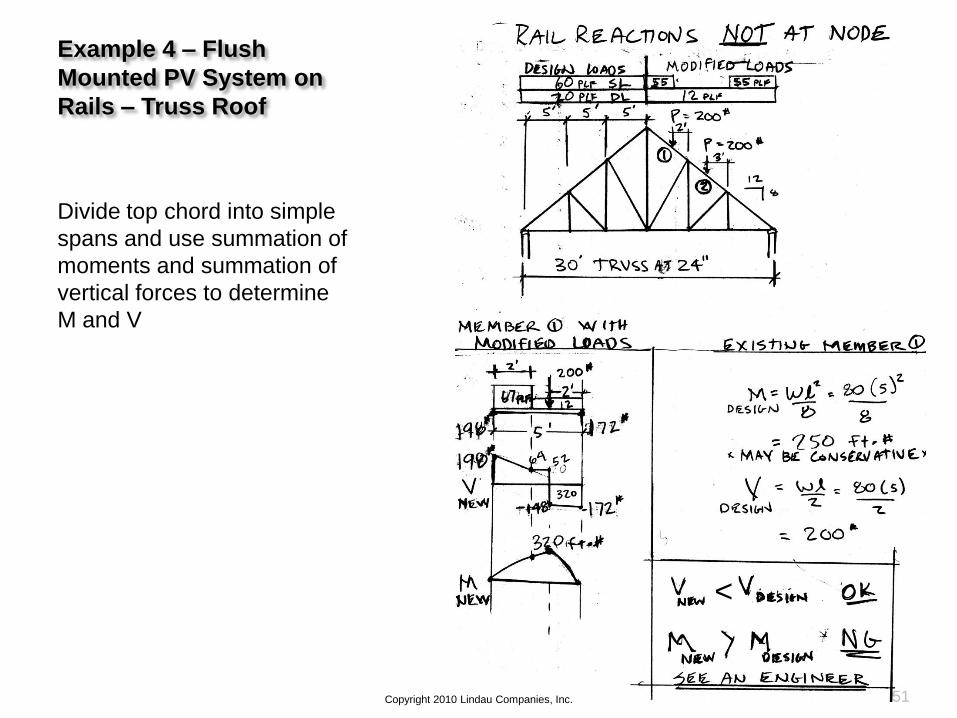
Example 4 – Flush
Mounted PV System on
Rails – Truss Roof
Divide top chord into simple
spans and use summation of
moments and summation of
vertical forces to determine
M and V
51Copyright 2010 Lindau Companies, Inc.
<
Example 4 – Flush
Mounted PV System on
Rails – Truss Roof
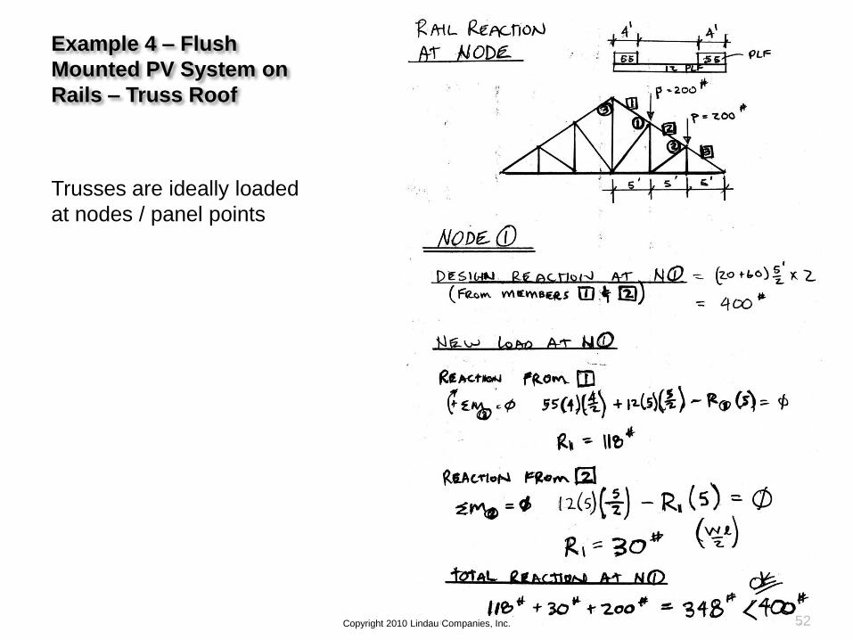
Trusses are ideally loaded
at nodes / panel points
52Copyright 2010 Lindau Companies, Inc.
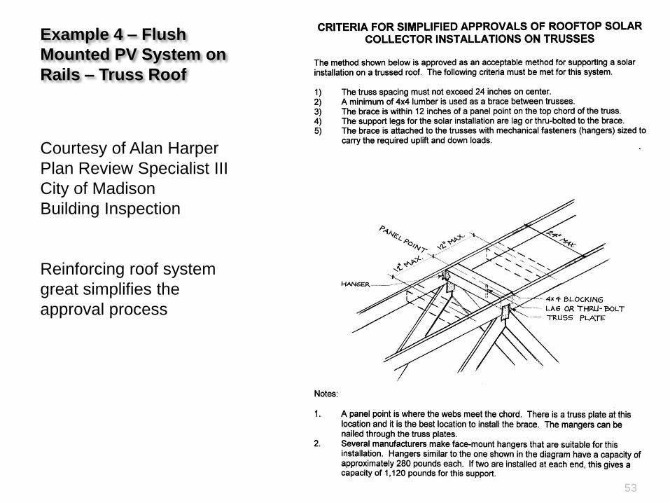
Example 4 – Flush
Mounted PV System on
Rails – Truss Roof
53
Courtesy of Alan Harper
Plan Review Specialist III
City of Madison
Building Inspection
Reinforcing roof system
great simplifies the
approval process
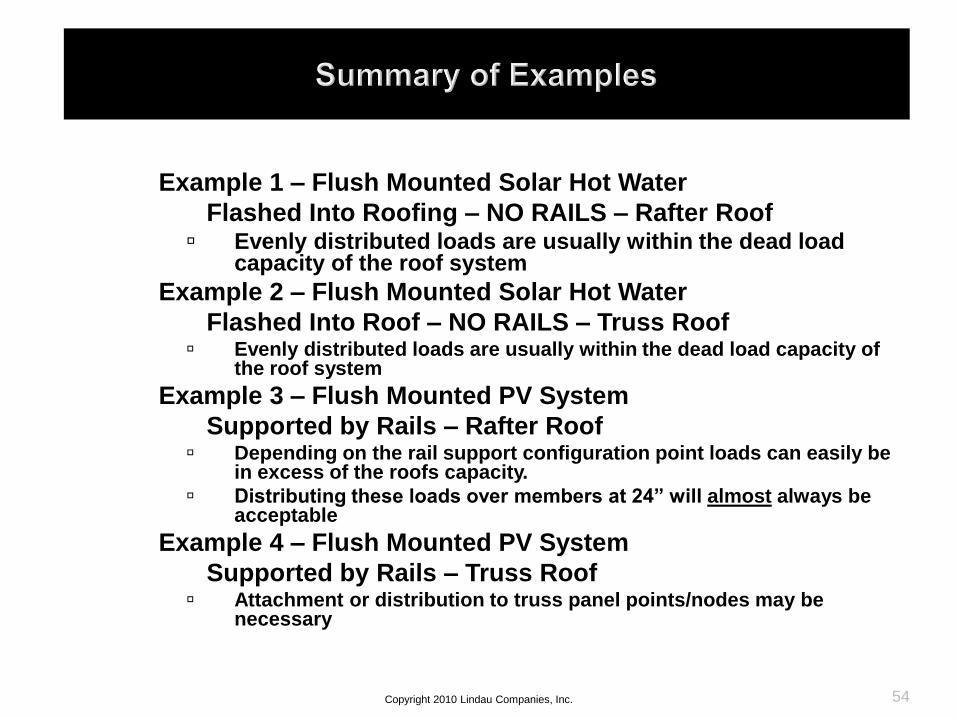
Example 1 – Flush Mounted Solar Hot Water
Flashed Into Roofing – NO RAILS – Rafter Roof Evenly distributed loads are usually within the dead load
capacity of the roof system
Example 2 – Flush Mounted Solar Hot Water
Flashed Into Roof – NO RAILS – Truss Roof Evenly distributed loads are usually within the dead load capacity of
the roof system
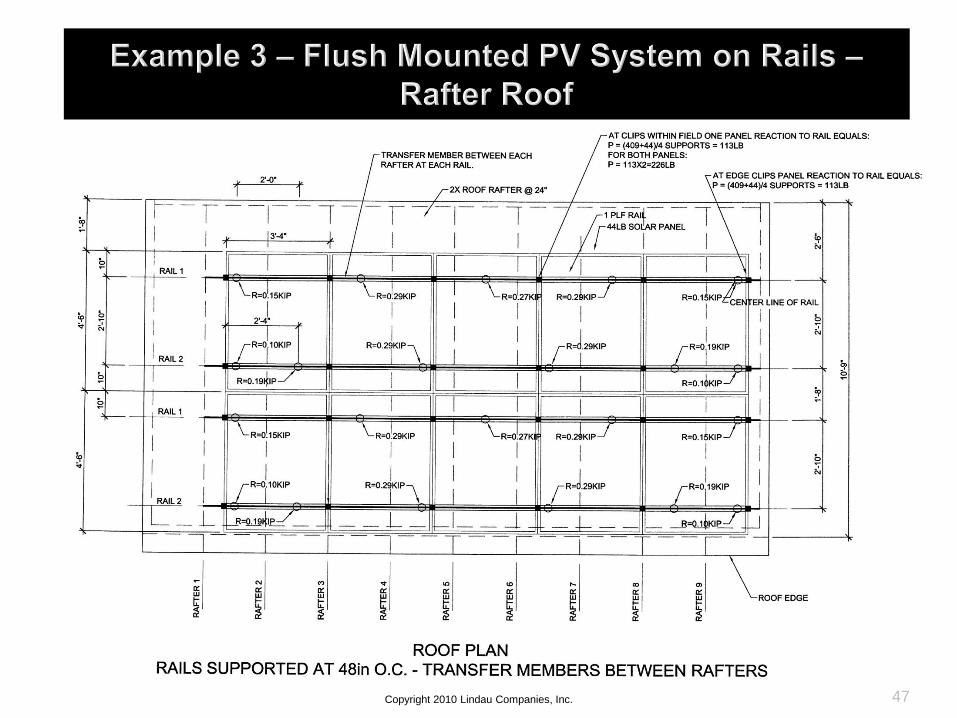
Example 3 – Flush Mounted PV System
Supported by Rails – Rafter Roof Depending on the rail support configuration point loads can easily be
in excess of the roofs capacity.
Distributing these loads over members at 24” will almost always be acceptable
Example 4 – Flush Mounted PV System
Supported by Rails – Truss Roof Attachment or distribution to truss panel points/nodes may be
necessary
54Copyright 2010 Lindau Companies, Inc.

55
Grading Existing Lumber
#2 Structural Framing
Source: National Grading Rule for
Dimension Lumber, “Standard Grading
Rules for West Coast Lumber No. 17”
(2004 edition), West Coast Lumber
Inspection Bureau
Courtesy of Alan Harper
Plan Review Specialist III
City of Madison
Building Inspection

56
Grading Existing Lumber
#2 Structural Framing
Source: National Grading Rule for
Dimension Lumber, “Standard Grading
Rules for West Coast Lumber No. 17”
(2004 edition), West Coast Lumber
Inspection Bureau
Courtesy of Alan Harper
Plan Review Specialist III
City of Madison
Building Inspection
57
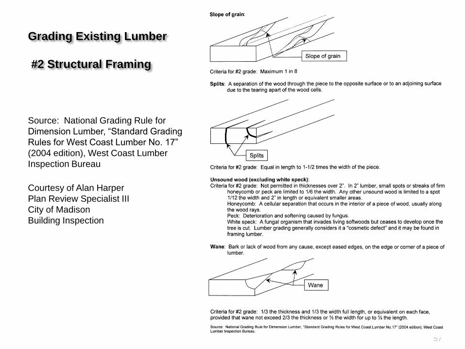
Grading Existing Lumber
#2 Structural Framing
Source: National Grading Rule for
Dimension Lumber, “Standard Grading
Rules for West Coast Lumber No. 17”
(2004 edition), West Coast Lumber
Inspection Bureau
Courtesy of Alan Harper
Plan Review Specialist III
City of Madison
Building Inspection

58
Copyright 2010 Lindau Companies, Inc. 59

Copyright 2010 Lindau Companies, Inc. 60
Copyright 2010 Lindau Companies, Inc. 61

Copyright 2010 Lindau Companies, Inc. 62

63Copyright 2010 Lindau Companies, Inc.

Structural Implications of Mounting Solar
Panels on a Residential Wood Structure
Ap
ril 3
0, 2
01
0
64
Cop
yrigh
t 2
01
0 L
ind
au
Com
pa
nie
s, In
c.
Top Related