


Languages
Pages
Legal

STRATIFIED-CHARGE TWO-STROKE STEPPED-PISTON ENGINE
ZULKARNAIN BIN ABDUL LATIFF
A thesis submitted in fulfilment of the
requirements for the award of degree of
Doctor of Philosophy (Mechanical Engineering)
Faculty of Mechanical Engineering
Universiti Teknologi Malaysia
DECEMBER 2011

iii
To my beloved late father and mother,
Your love brings me the happy and successful life
To my beloved wife and children,
Your encouragement and patience always give me spirit to achieve success
iv
ACKNOWLEDGEMENT
In the name of Allah S.W.T. that the Most Gracious and Most Merciful. May the peace
and blessing of Allat S.W.T. be upon Prophet Muhammad S.A.W.. Alhamdulillah, first
of all, my greatest gratitude goes to Allah S.W.T. for showing me ways of success which
make me possible to complete the project report. I would like to extend my
acknowledgement to all who were involved either directly or indirectly in completing
this work, whether their names were mentioned or otherwise in the following list: All
my family members especially my mother Rohani Che Tak and my late father Abdul
Latiff Alang; my beloved wife Noorlida Ali, my children: Iskandar, Khairunnisa and
Abdul Hafiz , my only sister: Rozmel; my outstanding supervisor: Prof. Ir. Dr. Azhar
Abdul Aziz; my sponsor: UTM; brilliant advices from Hishamudin Mohd Jamil, Sazali,
Aidid and Hj. Sairaji Suhadi; continuous support from Automotive Laboratory
personnel: Subki, Wan Mazian, Sadid, Samsuri; Aeronautic Laboratory: Johari;
Material Science Laboratory: Ayub, Jefri; Azri; Metrology Laboratory: Khalid;
Production Laboratory: Sukari; Central Store: Hamid, Ayob; Fellow
researchers: Mazlan, Fawzi, Ariffanan, Ng Tee Neng, Fong Kok Weng, Mohd Farid,
Nurudin, Zakaria, Bambang; Undergraduate colleagues: Balan, Ahmad Nazar,
Prabakaran; the good vendors: Fadli (AZMA), Lewis (Kistler); and all the authors cited
in the reference section. Thank you for your contribution in making this study a success.
v
ABSTRACT
A two-stroke stepped-piston prototype engine, in carbureted version was
designed and developed. It incorporates a unique three-port transfer system with an
accumulator for high induction efficiency, so as to perform very much like a two-stroke
engine but equipped with a four-stroke crankcase lubrication system. GT-Power
software was used in the development stage to predict the engine output. The data
predicted was then compared with the experimental results. A computational fluid
dynamic software, COSMOS/Floworks, was used to develop a computational model to
investigate the scavenging and compression processes of the prototype engine.The
prototype was subjected to a series of laboratory trials for engine performance and
emissions tests. Emission characteristics were established for regulated and unregulated
gases. From the engine performance test, maximum pressures attained from GT-Power
simulation and prototype engine were 54.62 bars at 5000 rpm and 26.12 bars at
4500 rpm respectively. Maximum indicated power produced is 11.25 kW at 8000 rpm
and 3.86 kW at 4500 rpm for GT-Power simulation and prototype engine respectively.
Torque, brake power and brake fuel consumption were also determined. For comparative
reason, a Yamaha 125Z engine was selected as the cylinder capacity with similar
working principle as the prototype engine. Torque produced by Yamaha 125Z was
highest, followed by GT-Power simulation and prototype engine. The average difference
of torque between Yamaha 125Z and GT-Power simulation was about 13.06%. The
minimum values of brake specific fuel consumption for Yamaha 125Z, GT-Power
simulation and prototype engine were 280.42 g/kWh at 3500 rpm, 351.08 g/kWh at
5000 rpm and 510 g/kWh at 3500 rpm respectively. The maximum peaks differences
were attributed to the differences of combustion chamber design used and assumptions
made in GT-Power.
vi
ABSTRAK
Dalam kajian ini sebuah enjin prototaip dua lejang omboh bertangga telah
direkabentuk dan dibangunkan dalam versi karburetor. Ia digabungkan dengan sistem
tiga liang hantaran dan pengumpul yang unik untuk kecekapan aruhan yang tinggi dan
berkelakuan seperti enjin dua lejang tetapi sistem pelinciran bersifat seperti kotak engkol
empat lejang. Perisisan GT-Power digunakan di peringkat pembangunan untuk meramal
keluaran enjin. Data teramal kemudian dibanding dengan keputusan ujikaji. Perisian
dinamik bendalir berkomputer, COSMOS/Floworks, digunakan untuk membina model
komputer untuk mengkaji proses menghapus sisa dan pemampatan enjin prototaip.
Kemudian prototaip menjalani satu siri ujian makmal untuk menentukan prestasi dan
emisi enjin. Emisi enjin ditentukan untuk gas terkawal dan tidak terkawal. Daripada
ujian prestasi enjin, tekanan maksimum simulasi GT-Power dan enjin prototaip masing-
masing adalah 54.62 bar pada 5000 ppm dan 26.12 bar pada 4500 ppm.. Kuasa tertunjuk
maksimum adalah 11.25 kW pada 8000 ppm dan 3.86 kW pada 4500 ppm untuk
simulasi GT-Power dan enjin prototaip. Dayakilas, kuasa brek dan pengunaan bahan api
tentu brek juga ditentukan. Bagi tujuan perbandingan, sebuah enjin Yamaha 125Z dipilih
memandangkan kapasiti silinder dan pinsip kerja yang sama dengan enjin prototaip.
Yamaha 125Z menghasilkan dayakilas tertinggi diikuti simulasi GT-Power dan enjin
prototaip. Perbezaan dayakilas purata antara Yamaha 125Z dan simulasi GT-Power
adalah 13.06%. Nilai minimum penggunaan bahan api tentu brek untuk Yamaha 125Z,
simulasi GT-Power dan enjin prototaip masing-masing adalah 280.42 g/kWh pada
3500 ppm, 351.08 g/kWh pada 5000 ppm dan 510 g/kWh pada 3500 ppm. Perbezaan
puncak maksimum yang terhasil adalah disebabkan oleh perbezaaan rekabentuk kebuk
pembakaran dan andaian yang digunakan dalam GT-Power.
vii
TABLE OF CONTENTS
CHAPTER TITLE PAGE
DECLARATION ii
DEDICATION iii
ACKNOWLEDGEMENTS iv
ABSTRACT v
ABSTRAK vi
TABLE OF CONTENTS vii
LIST OF TABLES xii
LIST OF FIGURES xiii
LIST OF SYMBOLS xvii
LIST OF ABBREVIATIONS xxii
LIST OF APPENDICES xxiv
1 INTRODUCTION 1
1.1 Introduction 1
1.2 Background of the Problem 3
1.3 Research Challenges 4
1.4 Research Questions 4
1.5 Hypothesis 5
1.6 Purpose of the Study 5
1.7 Importance of the Study 5
viii
1.8 Scope of the Study 6
2 LITERATURE REVIEW 9
2.1 Historical Background of Two-Stroke Engines 9
2.1.1 Two-Stroke Engines Development 9
2.2 Characteristics of the Two-Stroke Cycle Engine 13
2.3 The Fundamental Method of Operation of a Simple
Two-Stroke engine 15
2.4 Drawbacks of Two-Stroke Applications 18
2.5 The Future and Advances of Two-Stroke Engines 21
2.5.1 Gasoline Direct Injection 22
2.5.2 Homogenous Charge Compression Ignition 26
2.6 Future Applications of Two-stroke Engines 28
2.7 Stepped-Piston Engine 29
2.7.1 Stepped-Piston Engine Concept 30
2.8 The Proposed Two-Stroke Stepped Piston Engine 32
3 DESIGN AND SIMULATION 34
3.1 Introduction 34
3.2 Simulation for Flow 35
3.2.1 Computational Domain 35
3.2.2 Initial and Boundary Conditions 35
3.2.3 Meshing 36
3.2.4 Solving 36
3.2.5 Results Generation 37
3.2.6 Engine Parameter and Data Setting 37
3.2.6.1 Input Data 38
3.2.6.2 Simulation Results 40
3.2.7 Discussions 40
ix
3.3 Performance Simulation 42
3.3.1 Computer Simulation 50
3.3.1.1 The Stepped-Piston Engine Modeling 51
3.3.1.2 Intake and Exhaust Manifold Modeling 51
3.3.1.3 Intake Port Modeling 52
3.3.1.4 Combustion Modeling 52
3.3.1.5 Engine Cylinder Geometry 53
3.3.1.6 Piston Geometry 53
3.3.1.7 Cylinder Head Geometry 54
3.3.1.8 Emission Modeling 54
3.3.1.9 The Engine Model 55
3.3.2 Simulation Results 59
4 DEVELOPMENT OF PROTOTYPE ENGINE AND ENGINE
AUXILIARY SYSTEMS 65
4.1 Introduction 65
4.2 The Engine Design 67
4.2.1 Critical Components 68
4.2.1.1 Stepped-Piston 68
4.2.1.2 Connecting Rod and Crankshaft 69
4.2.1.3 Piston Pin 71
4.2.1.3 Cylinder Head 72
4.2.1.4 Cylinder Liner 73
4.2.1.5 Cylinder Block 74
4.2.2 Materials Selection 75
4.3 Basic Engine Design Parameters 76
4.4 Engine Auxiliary System 76
4.4.1 Breathing System 77
4.4.1.1 Breather Schematic diagram 77
4.4.1.2 Breather System Assembly 78
x
4.4.1.3 Testing for Performance 79
4.4.1.4 Experimental Results 81
4.4.2 Capacitive Discharge Ignition (CDI) 84
4.4.3 Add-on Module 86
5 ENGINE PERFORMANCE AND DATA ANALYSIS 89
5.1 Introduction 89
5.2 Experimental Work 89
5.3 Engine Testing Approach 90
5.3.1 Engine Performance Test Facilities 91
5.4 Engine Performance Test Results 93
5.4.1 Yamaha 125Z Engine Performance Results 95
5.4.2 Prototype Engine Test Results 97
5.5 Regulated Emission Test 98
5.5.1 Results of Yamaha 125Z 100
5.5.2 Results of Prototype Engine 101
5.6 Unregulated Emission Test 103
5.6.1 Test Results 103
5.6.1.1 Variable Engine Speed Test 104
5.6.1.2 Constant Speed and Variable Load Test 106
5.6.1.3 Constant Speed and Variable Lubrication
Oil (2-T) Content 106
5.7 Comparison of Test Results 110
5.7.1 In-Cylinder Pressure and Indicated Power 111
5.7.2 Torque, Brake Power and Brake Specific Fuel
Consumption 113
5.7.3 Concentration of CO2, CO and HC in Exhaust Gas 116
xi
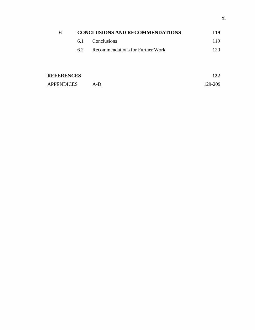
6 CONCLUSIONS AND RECOMMENDATIONS 119
6.1 Conclusions 119
6.2 Recommendations for Further Work 120
REFERENCES 122
APPENDICES A-D 129-209
xii
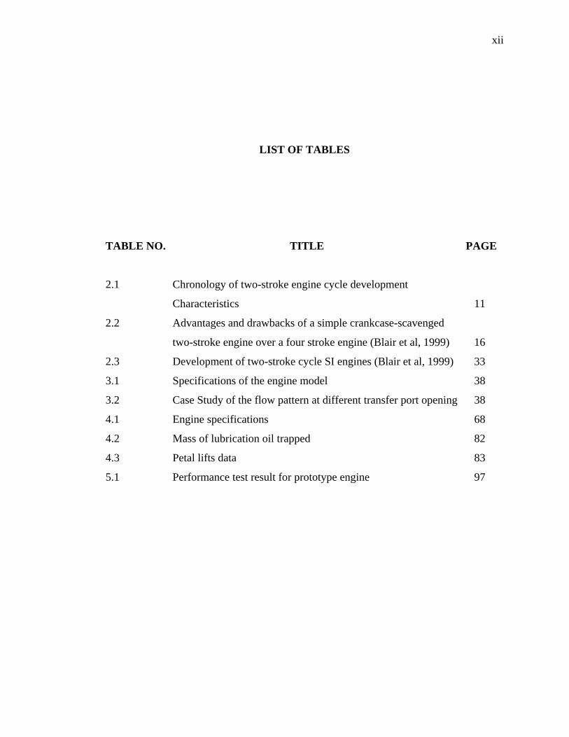
LIST OF TABLES
TABLE NO. TITLE PAGE
2.1 Chronology of two-stroke engine cycle development
Characteristics 11
2.2 Advantages and drawbacks of a simple crankcase-scavenged
two-stroke engine over a four stroke engine (Blair et al, 1999) 16
2.3 Development of two-stroke cycle SI engines (Blair et al, 1999) 33
3.1 Specifications of the engine model 38
3.2 Case Study of the flow pattern at different transfer port opening 38
4.1 Engine specifications 68
4.2 Mass of lubrication oil trapped 82
4.3 Petal lifts data 83
5.1 Performance test result for prototype engine 97
xiii
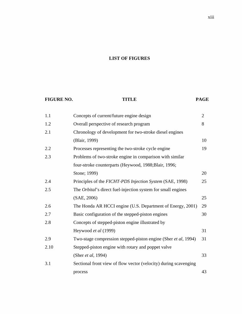
LIST OF FIGURES
FIGURE NO. TITLE PAGE
1.1 Concepts of current/future engine design 2
1.2 Overall perspective of research program 8
2.1 Chronology of development for two-stroke diesel engines
(Blair, 1999) 10
2.2 Processes representing the two-stroke cycle engine 19
2.3 Problems of two-stroke engine in comparison with similar
four-stroke counterparts (Heywood, 1988;Blair, 1996;
Stone; 1999) 20
2.4 Principles of the FICHT-PDS Injection System (SAE, 1998) 25
2.5 The Orbital’s direct fuel-injection system for small engines
(SAE, 2006) 25
2.6 The Honda AR HCCI engine (U.S. Department of Energy, 2001) 29
2.7 Basic configuration of the stepped-piston engines 30
2.8 Concepts of stepped-piston engine illustrated by
Heywood et al (1999) 31
2.9 Two-stage compression stepped-piston engine (Sher et al, 1994) 31
2.10 Stepped-piston engine with rotary and poppet valve
(Sher et al, 1994) 33
3.1 Sectional front view of flow vector (velocity) during scavenging
process 43
xiv
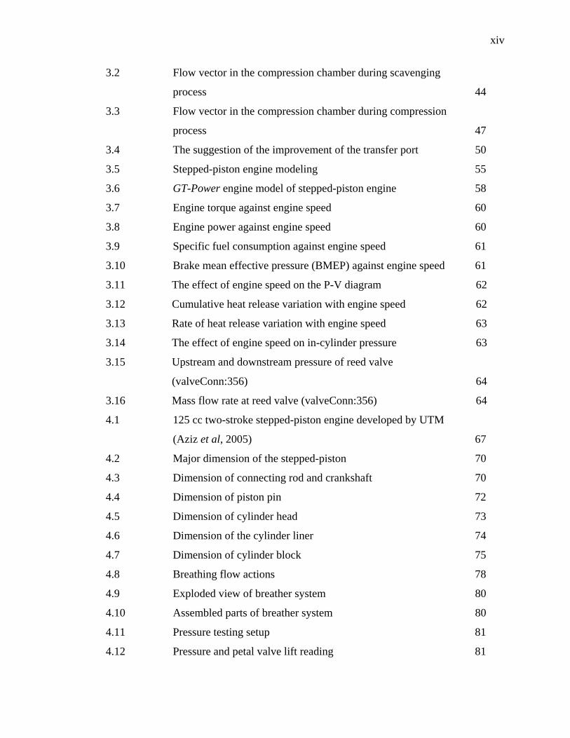
3.2 Flow vector in the compression chamber during scavenging
process 44
3.3 Flow vector in the compression chamber during compression
process 47
3.4 The suggestion of the improvement of the transfer port 50
3.5 Stepped-piston engine modeling 55
3.6 GT-Power engine model of stepped-piston engine 58
3.7 Engine torque against engine speed 60
3.8 Engine power against engine speed 60
3.9 Specific fuel consumption against engine speed 61
3.10 Brake mean effective pressure (BMEP) against engine speed 61
3.11 The effect of engine speed on the P-V diagram 62
3.12 Cumulative heat release variation with engine speed 62
3.13 Rate of heat release variation with engine speed 63
3.14 The effect of engine speed on in-cylinder pressure 63
3.15 Upstream and downstream pressure of reed valve
(valveConn:356) 64
3.16 Mass flow rate at reed valve (valveConn:356) 64
4.1 125 cc two-stroke stepped-piston engine developed by UTM
(Aziz et al, 2005) 67
4.2 Major dimension of the stepped-piston 70
4.3 Dimension of connecting rod and crankshaft 70
4.4 Dimension of piston pin 72
4.5 Dimension of cylinder head 73
4.6 Dimension of the cylinder liner 74
4.7 Dimension of cylinder block 75
4.8 Breathing flow actions 78
4.9 Exploded view of breather system 80
4.10 Assembled parts of breather system 80
4.11 Pressure testing setup 81
4.12 Pressure and petal valve lift reading 81
xv
4.13 Graph of speed versus mass of lubrication oil trapped 82
4.14 Petal on breather cover 83
4.15 Graph of petal valve lift versus pressure 84
4.16 The ignition system for the prototype engine 85
4.17 The exploded view showing the ignition system
enclosed in the engine’s front cover 86
4.18 Photographs showing the ignition system embedded
on the engine 87
4.19 The add-on module 87
4.20 The close-up of the add-on module 88
4.21 The prototype engine 88
5.1 Schematic arrangement of engine test set-up 94
5.2 Torque and brake power versus engine speed 96
5.3 bsfc and AFR versus engine speed 97
5.4 Torque and brake power versus engine speed for
prototype engine 99
5.5 Brake specific fuel consumption and air-fuel ratio versus
engine speed for prototype engine 99
5.6 CO2, CO, O2 and HC emissions from Yamaha 125Z engine 102
5.7 CO2, CO, O2 and HC emissions from prototype engine 102
5.8(a) Concentration against engine speed for prototype engine 105
5.8(b) Concentration against engine speed for Yamaha 125Z 105
5.8(c) Concentration of benzene against engine speed 105
5.8(d) Concentration of MTBE against engine speed 105
5.8(e) Concentration of toluene against engine speed 105
5.8(f) Concentration of 1,3-Butadiene against engine speed 105
5.8(g) Concentration against torque for prototype engine 107
5.8(h) Concentration against torque for Yamaha 125Z 107
5.8(i) Concentration of benzene against torque for prototype engine 107
5.8(j) Concentration of MTBE against torque for prototype engine 107
5.8(k) Concentration of toluene against torque for prototype engine 107
xvi
5.8(l) Concentration of 1,3-Butadiene against torque for
prototype engine 107
5.8(m) Concentration against percentage of 2-T for prototype
engine without load 109
5.8(n) Concentration against percentage of 2-T for prototype
engine with load at 5Nm 109
5.8(o) Concentration of benzene against percentage of 2-T at 1000rpm for
prototype engine 109
5.8(p) Concentration of MTBE against percentage of 2-T at 1000rpm for
prototype engine 109
5.8(q) Concentration of toluene against percentage of 2-T at 1000rpm for
prototype engine 111
5.8(r) Concentration of 1,3-butadiene against percentage of 2-T
at 1000rpm for prototype engine 111
5.9 In-cylinder pressure from GT-Power simulation 112
5.10 In-cylinder pressure versus crankangle for prototype engine 112
5.11 P-V diagram from GT-Power simulation 113
5.12 P-V diagram developed by prototype engine 113
5.13 Torque developed by GT-Power simulation, Yamaha 125Z
and prototype engine 114
5.14 Results of indicated power and brake power for both
GT-Power simulation and prototype engine testing 115
5.15 Results of brake fuel consumption for GT-Power simulation,
Yamaha 125Z and prototype engine 116
5.16 Major gas concentration versus engine speed 118
xvii
LIST OF SYMBOLS
Ap - Piston area
AFR - Air-fuel ratio
AFRs - Stochiometric air-fuel ratio
AFRt - Trapped air-fuel ratio
a - Crankshaft offset
B - Bore
BP - Brake power
Bfin - Breadth of single fin
b - Cylinder wall thickness
bmep - Brake mean effective pressure
bsfc - Brake specific fuel consumption
C - Specific heat
Cp - Specific heat at constant pressure
Cv - Specific heat at constant volume
CD - Coefficient of discharge
CRcc - Crankcase compression ratio
CRg - geometric compression ratio
CRt - trapped compression ratio
Cfl - Low calorific value for fuel
Dcw - Counter weight diameter
Dfw - Flywheel diameter
E - Energy
F - Force
xviii
Fgas - Force of gas
Fi - Inertia force
Fres - Total force acting on the piston
g - Gravitational acceleration
H - Piston height form TDC
hc - Heat transfer coefficient
I - Inertia
IP - Indicated power
isfc - indicated specific fuel consumption
j - Cylinder perimeter
Ks - Coefficient of fluctuating speed
k - Thermal conductivity
kx - Thermal conductivity in X direction
ky - Thermal conductivity in Y direction
kz - Thermal conductivity in Z direction
Lst - Stroke length
Lts - Trapped stroke length
Lcr - Connecting rod length
Lct - crank throw length
Lfin - Length of single fin
lc - Clearance volume height
mair - Mass of air
mca - Mass of cooling air
mf - Mass of fuel
mfw - Mass of flywheel
mcp - Mass of crank pin
mcrbe - Mass of connecting rod (big end)
mcrm - Mass of connecting rod (main)
mcrse - Mass of connecting rod (small end)
mcw - Mass of counter weight
mp - Mass of piston
xix
mpp - Mass of piston pin
mppb - Mass of piston pin bearing
mtcrbe - Total mass of connecting rod (big end)
mrot - Mass of rotating components
mrec - Mass of reciprocating components
mta - Mass of trapped air
mtf - Mass of trapped fuel
mtr - Total mass of charge
N - Speed
n - Number of cylinder
P - Pressure
Q - Volumetric heat generation rate
Qcool - Heat to be cooled
QR - Heat released from combustion
q - Heat flux
R - Ratio of connecting rod length to crank radius
Ra - Gas constant for air
Rtr - Gas constant at trapped point
rfw - Flywheel radius
Sp - Mean piston speed
Sexh - Exhaust perimeter
Smain - Main port perimeter
Sside - Side port perimeter
sfc - Specific fuel consumption
T - Temperature, torque
Tf - Tangential force
Ti - Indicated torque
To - Specified temperature
Ts - Surface temperature
Tat - Ambient temperature
Ttr - Trapped temperature
xx
T∞ - Ambient temperature
t - Time
tcw - Counter weight thickness
t1 - Thickness cylinder liner
U - Thermal load
V - Volume
Vcc - Crankcase volume
Vcv - Clearance volume
Vcw - Counter weight volume
Vsv - Swept volume
Vts - Trapped swept volume
Vtr - Trapped volume
fw - Flywheel velocity
X - Piston position
Greek Symbols
Ф - Angle of obliquity
γ - Specifics heat ratio
ε - Emissivity
ω - Angular velocity
ρ - Density
ρat - Air density
ρcw - Density of counter weight
σ - Stefan-Boltzmann constant
σfw - Stress of the flywheel
σc - Stress of cast iron
θ - Crank angle

xxi
ηc - Combustion efficiency
ηi - Indicated thermal efficiency
ηt - Thermal efficiency
xxii
LIST OF ABBREVIATIONS
AC - Alternate current
AFR - Air-fuel ratio
ATDC - After top dead center
A/D - analogue/digital
BDC - Bottom dead center
BTDC - Before top dead center
CA - Crank angle
CAD - Computer-aided design
CCD - Charge-coupled device
CDI - Capacitive discharge ignition
CFD - Computational fluid dynamics
CI - Compression ignition
CO - Carbon monoxide
CPU - Central processing unit
CVT - Continuous variable transmission
DAS - Data acquisition system
DFI - Direct fuel injection
DHA - Detail hydrocarbons analysis
ECU - Electronic control unit
EFIC - Electronic fuel injector controller
EGR - Exhaust gas recirculation
EPA - Environmental Protection Agency
EMS - Engine management system
xxiii
FEA - Finite element analysis
GDI - Gasoline direct injection
HC - Hydrocarbons
HCCI - Homogenous charge compression ignition
HPSGDi - High pressure swirl gasoline direct injector
ICE - Internal combustion engine
I/O - Input/output
MAP - Manifold absolute pressure
MTBE - Methyl tertiary-butyl ether
NO - Nitric oxides
NOx - Nitrogen oxides
PCB - Printed circuit board
PFI - Port fuel injection
PID - Proportional, integral and differentiate
PM - Particulate matter
PRV - Pressure relief valve
PWM - Pulse-width modulation
RAM - Read-access memory
ROM - Read-only memory
R&D - Research and development
SI - Spark ignition
SMD - Sauter mean diameter
SOI - Start of injection
TDC - Top dead center
TPS - Throttle position sensor
UTM - Universiti Teknologi Malaysia
ULEV - Ultra low emission vehicle
2-T - Lubrication oil
xxiv
LIST OF APPENDICES
APPENDIX NO. TITLE PAGE
A1 Input data for flow simulation 129
A2 Conversion of engine geometry to modeling objects
and windows of input data 134
B1 Typical design and operating data for internal combustion engines 139
B2 Materials Properties 140
B3 Thermodynamics and dynamics analysis 145
C1 Yamaha 125Z engine specifications 195
C2 Engine Performance Test Hardware Specifications 196
C3 Engine test set-up 206
C4 Roundness test results for the combustion and compression
chambers 207
C5 Unregulated test condition and results 208
D List of publications 209
CHAPTER 1
INTRODUCTION
1.1 Introduction
Internal combustion engine (ICE) technologies have undergone changes through
a series of phases since the 18th centuries. In the old days ICE was purely on mechanical
principles. With the advancement of technology, ICE had change from totally
mechanical dependent to electronic and computerized controlled system. No matter what
new technology was incorporated onto the engine, the main objective is to improvise
and develop a more efficient ICE in terms of output and emissions.
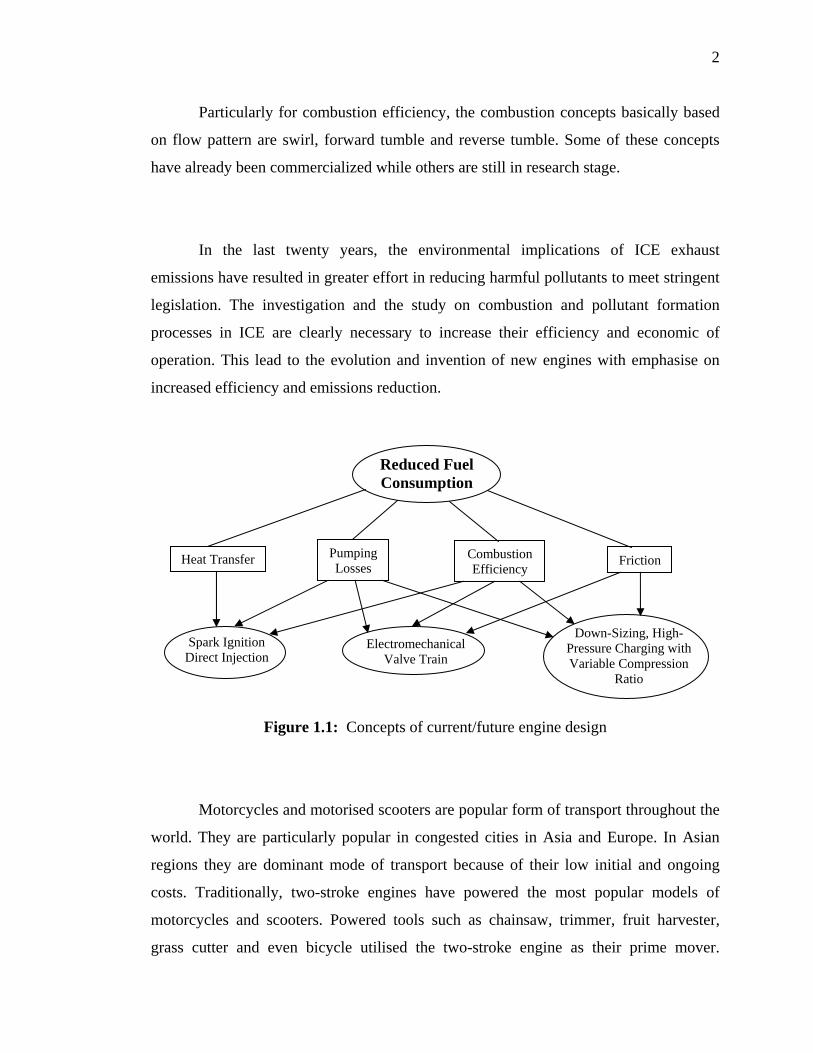
The improvement is basically to reduce fuel consumption or in other words to
utilise fuel efficiently. To achieve this goal, several concepts can be implemented. The
concepts are briefly shown in Figure 1.1.
2
Particularly for combustion efficiency, the combustion concepts basically based
on flow pattern are swirl, forward tumble and reverse tumble. Some of these concepts
have already been commercialized while others are still in research stage.
In the last twenty years, the environmental implications of ICE exhaust
emissions have resulted in greater effort in reducing harmful pollutants to meet stringent
legislation. The investigation and the study on combustion and pollutant formation
processes in ICE are clearly necessary to increase their efficiency and economic of
operation. This lead to the evolution and invention of new engines with emphasise on
increased efficiency and emissions reduction.
Figure 1.1: Concepts of current/future engine design
Motorcycles and motorised scooters are popular form of transport throughout the
world. They are particularly popular in congested cities in Asia and Europe. In Asian
regions they are dominant mode of transport because of their low initial and ongoing
costs. Traditionally, two-stroke engines have powered the most popular models of
motorcycles and scooters. Powered tools such as chainsaw, trimmer, fruit harvester,
grass cutter and even bicycle utilised the two-stroke engine as their prime mover.
Reduced Fuel Consumption
Spark Ignition Direct Injection
Heat Transfer Pumping Losses
Combustion Efficiency
Friction
Electromechanical Valve Train
Down-Sizing, High-Pressure Charging with Variable Compression
Ratio
3
Two-stroke engines are popular because they produce relatively high power from a
small size and are also inexpensive to manufacture and maintain. This is because the
two-stroke engine requires no valvetrain which contribute in major cost, weight and
complexity.
The current two-stroke designs are inefficient and impart environmental
implications to human and plants in urban and non-urban areas where they operate. In
Asian cities, they constitute the bulk of the engines for use in motorcycles and
three-wheelers. With the hazardous nature of the pollutants emitted by the vehicles they
are banned in Taipei, while in Bangkok the authority is seriously considering doing the
same. The somewhat low combustion efficiency of today’s two-stroke engine design can
be improved through various means, making it possible to compliment the four stroke
version. The latter is a more complicated engine configuration having lesser
power-to-weight ratio characteristic. During the last decade, there have been many
improved versions of the two-stroke engines produced. A few have found commercial
ventures while many are still at the prototype level or even on the drawing board.
1.2 Background of the Problem
The simplistic nature of the design of a two-stroke engine, with relatively simple
machining process (compared to four stroke engine), will provide improved
power-to-weight ratio characteristic and lower production cost. Development of new
two-stroke engines must address scavenging and emission problems. This can be
achieved through improvising the scavenging process. By means of multi-ports intake
system and eliminating crankcase compression, better scavenging process could be
4
achieved. The integration of transfer ports design to create better flow angle for
blowdown and loop scavenging of exhaust gases will help improve fuel consumption
and exhaust emissions in general. In this study the three numbers of ports was selected
due to the constraints of surface area. As for the eliminating of the crankcase
compression, stepped-piston configuration was selected in order to prepare the compress
air-fuel mixture for the scavenging process.
1.3 Research Challenges
The key research challenge that must be resolved is can a multi-port intake
system improve the performance and emission of a stratified-charged two-stroke
stepped-piston gasoline engine.
1.4 Research Questions
Some of the persistent questions at this juncture would be:
i) How multi-ports intake system and stepped-piston can fit in a two-stroke engine?
ii) How is the optimise condition be achieved?
iii) What effect will it have on performance and emission?
iv) What aspect of performance (torque, brake power, sfc, etc)?
v) What speed regime? Low speed? Typically idle to maximum speed?
vi) What load range?
vii) What are the impacts towards the unregulated and regulated exhaust emission?
5
1.5 Hypothesis
i) Multi-ports and stepped piston provides an effective mean of discarding exhaust
gases by introducing fresh charge through the circumference of the cylinder.
ii) It also improves the scavenging process by reducing the short-circuiting of fresh
charge air-fuel mixture.
1.6 Objectives of the Study
By introducing the multi-ports concept into the design of stratified-charged
stepped-piston engine the associated problems of the conventional design of two-stroke
engine can be addressed. The objectives of this research are as follows,
i) to analyse the impact of multi-ports and stepped-piston configuration towards
improving engine performance and emission,
ii) to determine the appropriate ports design configuration and location, and
iii) to compare the deviation between simulation and experimental results.
1.7 Importance of the Study
The study could benefit toward enhancing stratified-charged, two-stroke,
stepped-piston gasoline engine design with the potential for application in transport,
industrial and agriculture sectors. Furthermore, the future of the two-stroke engine will
6
depend upon how far a successful combination of scavenging, charging, combustion
technology improvement (this study) can be made without jeopardising its classical
advantages in terms of power density and simple construction.
1.8 Scope of the Study
Scopes of the study are as follows:
i) Design and simulation.
Preliminary study of the workability of the device is vital before the actual device is
being fitted to the actual engine. The best configuration of the device will be design
based on the actual boundary condition from the actual engine operation.
ii) Development and testing the prototype engine in laboratory for performance and
emission.
A two-stroke engine will be developed to distinguish the workability of the system.
iii) Engine testing for performance and emission.
In this exercise two intensive testing will be conducted. Firstly the developed
engine characteristic will be defined and secondly an engine which is available in
the market which has the same capacity will be undergoing the same testing for
comparative study.
iv) Data analysis.
All the data obtained from the testing will be analysed in order evaluate engine
performance and emission.
7
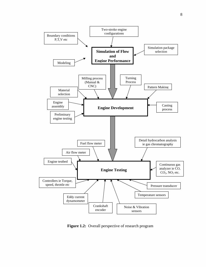
In general, the outline constitutes three major areas in meeting the objectives and
they are:
i) Simulation of flow and engine performance
To observe the flow characteristic during scavenging of exhaust gases and also the
compression of fresh air-fuel mixture by the steppe-piston. As for the engine
performance simulation is to observe the typical engine characteristics based on
the engine geometry.
ii) Engine development
To look into the appropriate design features in order to have a optimize engine.
This exercise will involve decision making in choosing the right method in
producing each component of the engine without compromising with the vital
features.
iii) Engine performance testing.
The testing comprises of conventional two-stroke and prototype engine. The
purpose of the conventional engine testing is intended for comparative study.
The overall perspective of the research program is shown in Figure 1.2.
8
Two-stroke engine configurations Boundary conditions
P,T,V etc
Figure 1.2: Overall perspective of research program
Simulation of Flow and
Engine Performance
Simulation package selection
Modeling
Turning Process
Milling process (Manual &
CNC) Pattern MakingMaterial selection
Engine Development
Engine assembly Casting
process Preliminary
engine testing
Engine Testing
Fuel flow meter
Noise & Vibration sensors
Eddy current dynamometer
Continuous gas analyzer ie CO, CO2, NO2 etc.
Pressure transducer
Temperature sensors
Controllers ie Torque, speed, throttle etc
Engine testbed
Detail hydrocarbon analysis ie gas chromatography
Air flow meter
Crankshaft encoder
122
REFERENCES
ADB (2003). Policy Guidelines for Reducing Vehicle Emissions in Asia. Philipines:
Asian Development Bank.
Adler, U. (1989). Automotive Handbook: 18th Edition., Stuttgart: Robert Bosch.
AK Steel (2000). 316/316L Stainless Steel (Product Data Sheet). Ohio, USA: AK Steel
Corporation.
Alger, T, Hall, M and Ronald, D (2000). Effects of Swirl and Tumble on In-Cylinder
Fuel Distribution in a Central Injected DISI Engine, SAE Technical Paper,
No. 2000-01-0533, 2000.
Aziz, A. A., Latif, Z. A., Mohamad, M. F. M., and Ming, G. L. (2005). Development of
a 125 cc Two-stroke, Step-piston Engine Using a One-dimensional Engine Code.
Journal of KONES Internal Combustion Engines 2005, Vol. 12, 1-2, pp. 23-30.
Badami, M., Marzano, M. R., Millo, F., and Nuccio, P. (1999). Comparison between
Direct and Indirect Fuel Injection in an S.I. Two-Stroke Engine. SAE Technical
Paper, No. 1999-01-3311.
Blair, G.P. and Ashe, M.C. (1976). The Insteady Gas Exchange Characteristics of a
Two-Stroke Cycle Engine. SAE Paper No.: 760644.
Blair, G.P. (1990). The Design of Two-Stroke Engines, Society of Automotive
Engineers, Warrendale, Pennsylvania, USA, pp 672, SAE ref no.: R-104, ISBN
1-56091-008-9
123
Blair, G.P. (1985). Patent Number 4,522,163. Design and Simulation of Two-Stroke
Engines. USA: United State Patent (SAE Publications).
Carney, D. (2003). Toyota launches the Camry PZEV. American Enterprise Institute
Article (page 39). USA: A.E.I.
Casarella, M. V., Syvertsen, M. L., Martin, J. K., Hoffman, J. A., Ghandhi, J. B., Coates,
S. W., and McGinnity, F. A. (1997). Spray Combustion and Emissions in a
Direct Injection Two Stroke Engine with Wall-stabilization of an Airassisted
Spray. SAE Technical Paper, No. 970360.
COSMOS (2001). COSMOS/FloWorks User’s Guide Revision 8. U.S.: COSMOS.
Fleck, R. (1990). Three-Cylinder, Natural Aspirated, Two-Stroke Automotive Engines –
A Performance Potential Evaluation. SAE Technical, Paper No.: 901667.
Franz, J. L. (1991). The Low Emissions High Output Two-Stroke S.I. Engine with
Catalyst. Paper presented at the Seminar and Workshop on Design and
Development of Two-Stroke Engines for Automotive Applications. Belfast:
University of Queensland.
Fox, R.W. and McDonald, A.T. (1985), Introduction to Fluid Mechanic. (Third Edition).
U.S.: John Wiley and Sons Inc..
Gentili, R., Zanforlin, S., Frigo, S., Cozzolino, F., Dell’orto, P., and Doveri, C. (2002).
Optimization of a Stratified Charge Strategy of a Direct Injected Two Stroke
Engine. SAE Technical Paper, No. 2002-32-1785.
Heywood, J.B. and Sher, E (1999), The Two-Stroke Cycle Engine: Its Development,
Operation and Design. USA: SAE International Publications.
124
Heywood, J.B. (1988). Internal Combustion Engine Fundamentals. New York: McGraw
Hill Inc.
Irwing, P.E. (1967). Two-Stroke Power Units, Their Design and Application. Temple
Press Books for Newnes: London.
Hooper, B. (1985). Stepped Piston and Stepped Piston Engine. Patent No. 4,522,163
USA: USA. Patent)
Hull, W., Beu, J., Jorenby, J., Lentz, J., Hoss, J., Pickard, G., Jamison, F., Mathis, T.,
and Willson, B. (2003). Optimization of a Direct-Injected 2-Stroke Cycle
Snowmobile. SAE Technical Paper, No. 2003-32-0074.
Kang, J.M., Chang, F.C., Chen, J.S. and Chang, M.F. (2009). Concept and
Implementation of a Robust HCCI Engine Controller. SAE Technical Paper, No.
2009-01-1131.
Masahiko, F. and Michihiko, T. (1993). Effect of Swirl Rate Formation in a Spark
Ignition Based on Laser 2-D Visualization Techniques. SAE Technical Paper,
No. 931905.
Metals Handbook (1964). Properties and Selection of Metals Vol. 1. Metal s Park: OH:
American Society for Metals.
Mitianiec, W. (2003). Reduction of Exhaust Gas Emission in a SI Two Stroke Engine
with Direct Fuel Mixture Injection. SAE Technical Paper, No. 2003-32-0048.
Morikawa, K., Takimoto, H, and Ogi, T. (1999). A Study of Direct Fuel Injection Two-
stroke Engine for High Specific Power Output and High Engine Speed. SAE
Technical Paper, No. 1999-01-3288.
125
Nishimoto, K and Kamimoto, K. (1984). A Study on the Influence of inlet Angle and
Reynolds Number on the Flow-Pattern of Uniflow Scavenging Air. SAE Paper.
No.: 841056.
Nuccio, P., and Marzano, M. R. (2003). Performance Improvement of Two-Stroke SI
Engines for Motor-Gliders and Ultra-Light Aircraft By Means of a GDI System.
SAE Technical Paper, No. 2003-32-0002.
Oil-Hydraulics (1982). Fluid Power Technical Manual. Hydro-Pneumatic Technical
Centre, Japan: The Japan Oil Hydraulics Association.
Pontoppidan, M., Nuti, M., Caponi, D., de Maio, A., and Andreassi, A. (1999).
Experimental and Numerical Approach to Productionizing a GDI 2-Stroke Spark
Ignited Small Displacement Engine Design. SAE Technical Paper, No.
1999-01-3290.
Preussner, C., Döring, C., Fehler, S. and Kampmann, S. (1998). GDI: Interaction
between Mixture Preparation, Combustion System and Injector Performance.
SAE Technical Paper, No. 980498.
Ramakrishanan, E., Nagalingam, B. and Gopalakrishnan, K. V. (2001). Improving the
Performance of Two-Stroke Spark Ignition Engines by Direct Injection. SAE
Technical Paper, No. 2001-01-1843/4262.
Blair, G.P. (1998). Two-Stroke Engines: Technology and Emissions. United State: SAE
International.
SAEJ1832 (2001). Low Pressure Gasoline Fuel Injector. SAE Surface Vehicle
Recommended Practice, No. SAEJ1832v002
126
SAE (2006). Focus on Electronics, Managing for Software Success, Automotive
Engineering International, SAE International, August 2006.
Seong, S.K (1995). Effects of Swirl and Spark Plug Shape on Combustion Characteristic
in a High Speed Single-Shot Visualized SI Engine. SAE Technical Paper,
No. 951003.
Sher, E. and Zeigerson, M. (1994). A Stepped-Piston Two-Stroke Engine for High
Altitude Application. SAE Paper, No. 9404400.
Sher, E. and Zeigerson, M. (1999). A Stepped-Piston Two-Stroke Engine for High
Altitude Application., SAE 9404400, 1994. Patent Number 5,870,980, United
Sates Patent, 16th
February 1999.
Sherman, E.R. (1997). Outboard Engines: Maintenance, Troubleshooting and Repair.
United States: McGrawhill.
Sherman, D. (2009), The Two-Stroke Engine’s Revival. Automobile Magazine.
December Issue. U.S.
Shigley, I.E. (1977). Mechanical Engineering Design, 3rd Edition, International Student
Edition. Singapore: McGraw-Hill International.
Shigley, E.S. and Mitchell, L.O. (1983). Mechanical Engineering Design, International
Student, 4th. Edition. Singapore: McGraw-Hill International.
Stan, C. C., Lefebvre, J. L., and Lebrun, M. (1999). Development, Modeling and Engine
Adaptation of a Gasoline Direct Injection System for Scooter Engines. SAE
Technical Paper, No. 1999-01-3313.
127
STMicroelectronics (1999). BDX53B/BDX53C/BDX54B/BDX54C Complimentary
Silicon Power Darlington Transistor. Electronics Components Datasheet. Italy:
STMicroelectronics
Sweeney, M.E.G., Kenny, R.G., Swann, G.B.G., and Blair, G.P. (1985). Single Cycle
Gas Testing Method for Two-Stroke Engine Scavenging, SAE paper No. 850178.
US Department of Energy (2001). Homogenous Charge Compression Ignition (HCCI)
Technology: A Report to the U.S. Congress. United States: U.S. Department of
Energy.
Valentine, A.S. and Nicole, B. (1999). Variable Intake System for Tumble Motion
Stratified Charge in Spark Ignition Engine. JSAE Yokohama 1999, Presentation
No. 74.
Wang, Z., Wang, J.X., Shuai, S.J. and Ma, Q.J. (2005). Effects of Spark Ignition and
Stratified Charge on Gasoline HCCI Combustion With Direct Injection. SAE
Technical Paper, No. 2005-01-0137.
Willard.W.P. (2004). Engineering Fundamentals of the Internal Combustion Engine.
Pearson Prentice-Hall. Upper Saddle River, New Jersey.
Wilhemsson, C., Tunest, P. and Johansson, B. (2007). Operation strategy of a Dual Fuel
HCCI Engine with VGT. SAE Technical Paper, No. 2007-01-1855.
Winterbone, D.E. (1987). The Application of Gas Dynamics for the Design of Engine
Manifolds, IMechE Paper No.: CMT8701.
128
Zhao, F. Q., Lai, M. C., and Harrington, D. L. (1997). A Review of Mixture Preparation
and Combustion Control Strategies for Spark-Ignited Direct- Injection Gasoline
Engines. SAE Technical Paper, No. 970627.
Zhoa, H and Ladommatos, N (2001), Engine Combustion, Instrumentation and
Diagnostic, SAE Inc., Warrendale, Pa.
Zhao, F. Q., Harrington, D. L., and Lai, M. C. (2002). Automotive Gasoline Direct-
Injection Engines. Warrendale, PA, USA: SAE Publications.
Top Related