


Languages
Pages
Legal

278
http://www.pisco.co.jp
Stop FittingSeries
RotarySeries
Twist-ProofFitting
Block andConnector
Coupling
ColorCap
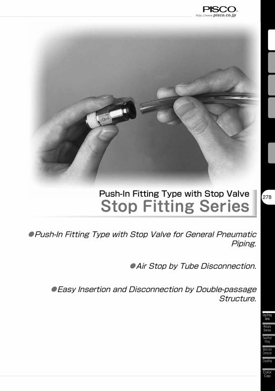
Push-In Fitting Type with Stop ValveStop Fitting Series
●Push-In Fitting Type with Stop Valve for General Pneumatic Piping.
●Easy Insertion and Disconnection by Double-passage Structure.
●Air Stop by Tube Disconnection.
Fitting SeriesStop Fitting Series
Stop FittingSeries
279
MinimalSeries
Die TemperatureControl
Anti-spatter& Brass Series
EGSeries
PPSeries
ChemicalSeries
StainlessSeries
MiniSeries
StandardSeries
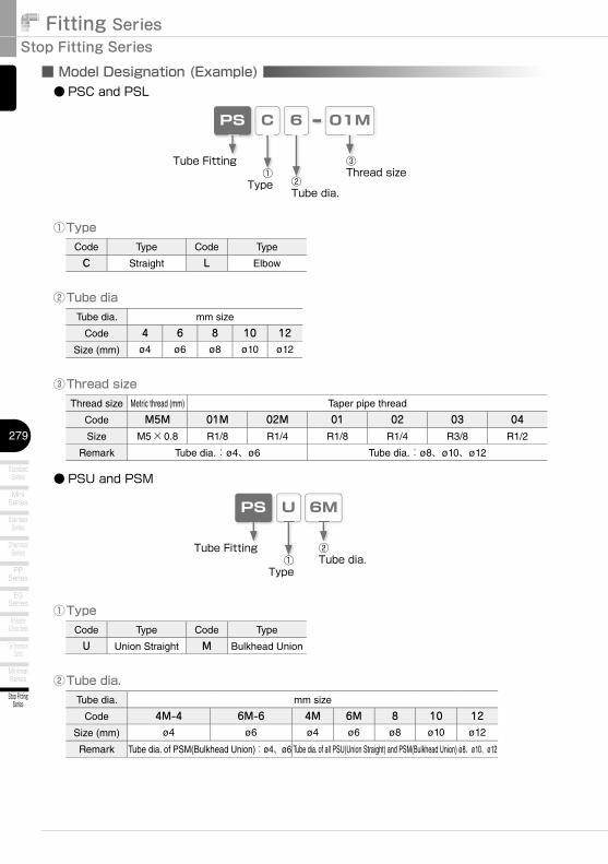
■ Model Designation (Example)
CPS 6 01M
②Tube dia
③Thread size Thread size Metric thread (mm) Taper pipe thread
Code M5M 01M 02M 01 02 03 04Size M5×0.8 R1/8 R1/4 R1/8 R1/4 R3/8 R1/2
Remark Tube dia.:ø4、ø6 Tube dia.:ø8、ø10、ø12
Code Type Code Type
C Straight L Elbow
①Type
Tube dia. mm size
Code 4 6 8 10 12Size (mm) ø4 ø6 ø8 ø10 ø12
Tube Fitting①
Type
③Thread size
②Tube dia.
UPS 6M
②Tube dia.
Code Type Code Type
U Union Straight M Bulkhead Union
①Type
Tube dia. mm size
Code 4M-4 6M-6 4M 6M 8 10 12Size (mm) ø4 ø6 ø4 ø6 ø8 ø10 ø12
Remark Tube dia. of PSM(Bulkhead Union):ø4、ø6 Tube dia. of all PSU(Union Straight) and PSM(Bulkhead Union) ø8、ø10、ø12
Tube Fitting①
Type
②Tube dia.
● PSC and PSL
● PSU and PSM
280
http://www.pisco.co.jp
Stop FittingSeries
RotarySeries
Twist-ProofFitting
Block andConnector
Coupling
ColorCap
■ SpecificationsFluid medium Air
Max. operating pressure 0.9MPa
Max. vacuum -100kPa
Operating temp. range 0~60℃ (No freezing)
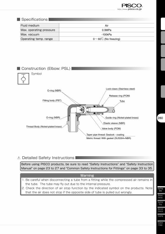
■ Construction (Elbow: PSL)
Elastic sleeve (NBR)
Taper pipe thread: Sealock - coating
Metric thread: With gasket (SUS304+NBR)
Tube
Release ring (POM)
Lock-claws (Stainless steel)O-ring (NBR)
Fitting body (PBT)
Thread Body (Nickel-plated brass)
Guide ring (Nickel-plated brass)
Detailed Safety InstructionsBefore using PISCO products, be sure to read “Safety Instructions” and “Safety Instruction Manual” on page 23 to 27 and “Common Safety Instructions for Fittings” on page 33 to 35.
Warning1. Be careful when disconnecting a tube from a fitting while the compressed air remains in
the tube. The tube may fly out due to the internal pressure.2. Check the direction of air stop function by the indicated symbol on the products. Note
that the air does not stop if the opposite side of tube is pulled out wrongly.
Valve body (POM)
O-ring (NBR)
Symbol
Fitting SeriesStop Fitting Series
Stop FittingSeries
281
MinimalSeries
Die TemperatureControl
Anti-spatter& Brass Series
EGSeries
PPSeries
ChemicalSeries
StainlessSeries
MiniSeries
StandardSeries
Type Page Thread sizeTube O.D. (mm)
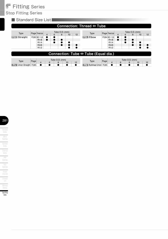
4 6 8 10 12PSC Straight P.283 M5×0.8 ● ●
R1/8 ● ● ●R1/4 ● ● ●R3/8 ● ● ●R1/2 ● ●
■ Standard Size ListConnection: Thread ⇔ Tube
Connection: Tube ⇔ Tube (Equal dia.)
Type PageTube O.D. (mm)
4 6 8 10 12PU Union Straight P.285 ● ● ● ● ●
Type Page Thread sizeTube O.D. (mm)
4 6 8 10 12PSL Elbow P.284 M5×0.8 ● ●
R1/8 ● ● ●R1/4 ● ● ●R3/8 ● ● ●R1/2 ● ●
Type PageTube O.D. (mm)
4 6 8 10 12PM Bulkhead Union P.285 ● ● ● ● ●
282
http://www.pisco.co.jp
Stop FittingSeries
RotarySeries
Twist-ProofFitting
Block andConnector
Coupling
ColorCap
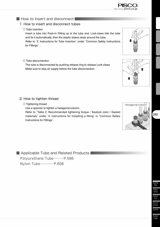
■ How to insert and disconnect1. How to insert and disconnect tubes
① Tube insertion
Insert a tube into Push-In Fitting up to the tube end. Lock-claws bite the tube
and fix it automatically, then the elastic sleeve seals around the tube.
Refer to “2. Instructions for Tube Insertion” under “Common Safety Instructions
for Fittings” .
② Tube disconnection
The tube is disconnected by pushing release-ring to release Lock-claws.
Make sure to stop air supply before the tube disconnection.
2. How to tighten thread① Tightening thread
Use a spanner to tighten a hexagonal-column.
Refer to “Table 2: Recommended tightening torque / Sealock color / Gasket
materials” under “4. Instructions for Installing a fitting” in “Common Safety
Instructions for Fittings”.
Hexagonal-column
■ Applicable Tube and Related ProductsPolyurethane Tube………P.596Nylon Tube…………P.608
Fitting SeriesStop Fitting Series
Stop FittingSeries
283
MinimalSeries
Die TemperatureControl
Anti-spatter& Brass Series
EGSeries
PPSeries
ChemicalSeries
StainlessSeries
MiniSeries
StandardSeries
CAD data is available at PISCO website.CAD
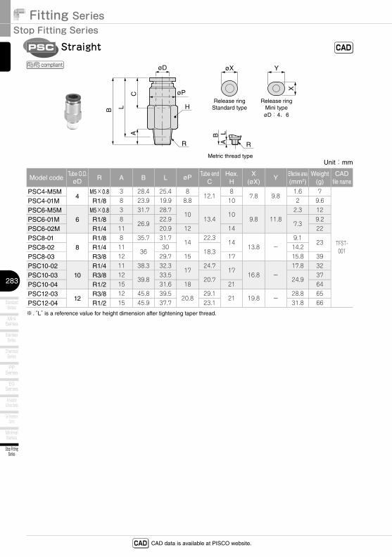
PSC
Unit:mm
Model codeTube O.D.
øD R A B L øP Tube endC
Hex.H
X(øX)
YEffective area(mm2)
Weight(g)
CADfile name
PSC4-M5M4
M5×0.8 3 28.4 25.4 812.1
87.8 9.8
1.6 7
TFST-001
PSC4-01M R1/8 8 23.9 19.9 8.8 10 2 9.6
PSC6-M5M6
M5×0.8 3 31.7 28.710
13.410
9.8 11.82.3 12
PSC6-01M R1/8 826.9
22.97.3
9.2
PSC6-02M R1/4 11 20.9 12 14 22
PSC8-018
R1/8 8 35.7 31.714
22.314
13.8 -9.1
23PSC8-02 R1/4 11
3630
18.314.2
PSC8-03 R3/8 12 29.7 15 17 15.8 39
PSC10-0210
R1/4 11 38.3 32.317
24.717
16.8 -17.8 32
PSC10-03 R3/8 1239.8
33.520.7 24.9
37
PSC10-04 R1/2 15 31.6 18 21 64
PSC12-0312
R3/8 12 45.8 39.520.8
29.121 19.8 -
28.8 65
PSC12-04 R1/2 15 45.9 37.7 23.1 31.8 66
※ . “L” is a reference value for height dimension after tightening taper thread.
R R
øD
øPC
LB H
A
Metric thread type
BA
L
Release ringMini type
Release ringStandard type
øD:4、6
YøX
X
CADStraight
compliant
284
http://www.pisco.co.jp
Stop FittingSeries
RotarySeries
Twist-ProofFitting
Block andConnector
Coupling
ColorCap
CAD data is available at PISCO website.CAD
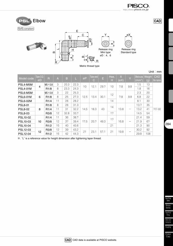
PSL
Unit:mm
Model codeTube O.D.
øD R A B L øP Tube endC
EHex.
HX
(øX)Y
Effective area(mm2)
Weight(g)
CADfile name
PSL4-M5M4
M5×0.8 3 20.3 22.310 12.1 29.7 10 7.8 9.8
1.5 13
TFST-002
PSL4-01M R1/8 8 23.3 24.3 1.8 16
PSL6-M5M6
M5×0.8 3 22 25.312.5 13.4 30.1
127.8 9.8
2.3 20
PSL6-01M R1/8 8 25 27.3 6.8 22
PSL6-02M R1/4 11 28 28.2 14 8.1 30
PSL8-018
R1/8 8 28 31.314.5 18.3 43
1413.8 -
13.7 35
PSL8-02 R1/4 11 31 32.2 13.2 41
PSL8-03 R3/8 12 32.8 33.7 17 14.5 54
PSL10-0210
R1/4 11 36 38.717.5 20.7 49.3
1716.8 -
21.4 59
PSL10-03 R3/8 12 37 39.4 21.9 67
PSL10-04 R1/2 15 40 40.6 21 21.3 90
PSL12-0312
R3/8 12 39 43.221 23.1 57.1 21 19.8 -
30.2 92
PSL12-04 R1/2 15 42 44.3 29.8 108
※ . “L” is a reference value for height dimension after tightening taper thread.
R R
øDø
P CE
LB
H
A
Metric thread type
BA
L
Release ringMini type
Release ringStandard type
øD:4、6
Y øX
X
CADElbow
compliant
Fitting SeriesStop Fitting Series
Stop FittingSeries
285
MinimalSeries
Die TemperatureControl
Anti-spatter& Brass Series
EGSeries
PPSeries
ChemicalSeries
StainlessSeries
MiniSeries
StandardSeries
CAD data is available at PISCO website.CAD
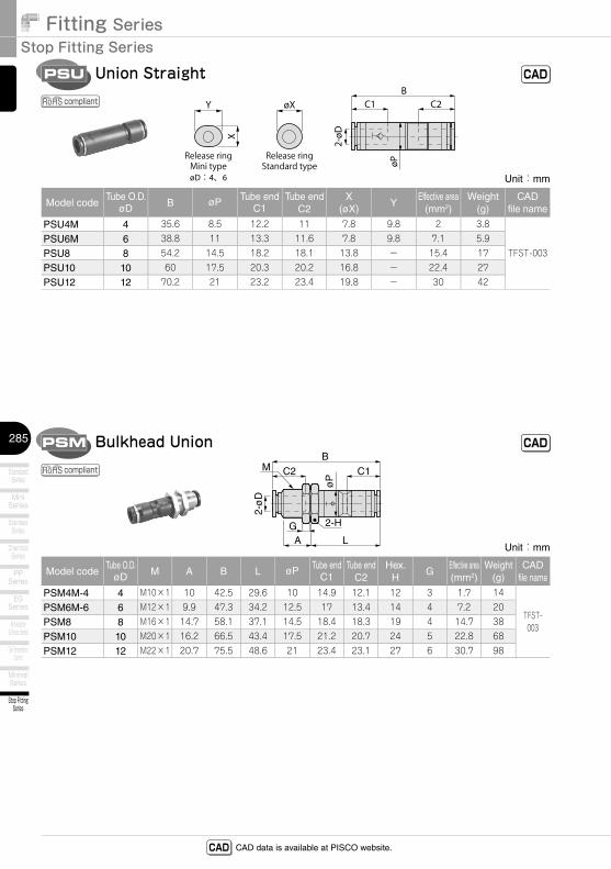
2-øD
øP
C1 C2B
Release ringMini type
Release ringStandard type
øD:4、6
Y øX
X
Unit:mm
Model codeTube O.D.
øD B øP Tube endC1
Tube endC2
X(øX)
YEffective area
(mm2)Weight
(g)CAD
file name
PSU4M 4 35.6 8.5 12.2 11 7.8 9.8 2 3.8
TFST-003PSU6M 6 38.8 11 13.3 11.6 7.8 9.8 7.1 5.9
PSU8 8 54.2 14.5 18.2 18.1 13.8 - 15.4 17
PSU10 10 60 17.5 20.3 20.2 16.8 - 22.4 27
PSU12 12 70.2 21 23.2 23.4 19.8 - 30 42
2-ø
D
øP
C1C2
B
GA L
M
2-H
Unit:mm
Model codeTube O.D.
øD M A B L øP Tube endC1
Tube endC2
Hex.H
GEffective area(mm2)
Weight(g)
CADfile name
PSM4M-4 4 M10×1 10 42.5 29.6 10 14.9 12.1 12 3 1.7 14
TFST-003
PSM6M-6 6 M12×1 9.9 47.3 34.2 12.5 17 13.4 14 4 7.2 20
PSM8 8 M16×1 14.7 58.1 37.1 14.5 18.4 18.3 19 4 14.7 38
PSM10 10 M20×1 16.2 66.5 43.4 17.5 21.2 20.7 24 5 22.8 68
PSM12 12 M22×1 20.7 75.5 48.6 21 23.4 23.1 27 6 30.7 98
Union Straight
Bulkhead Union
PSU
PSM
CAD
CAD
compliant
compliant
23
Safety Instructions
SAFETY Instructions
Warning
This safety instructions aim to prevent personal injury and damage to properties by requiring proper use of PISCO products. Be certain to follow ISO 4414 and JIS B 8370
ISO 4414:Pneumatic fluid power…Recomendations for the application of equipment to transmission and control systems.
JIS B 8370:General rules and safety requirements for systems and their components.This safety instructions is classified into “Danger”, “Warning” and “Caution” depending on the degree of danger or damages caused by improper use of PISCO products.
1. Selection of pneumatic products① A user who is a pneumatic system designer or has sufficient experience
and technical expertise should select PISCO products.② Due to wide variety of operating conditions and applications for PISCO
products, carry out the analysis and evaluation on PISCO products. The pneumatic system designer is solely responsible for assuring that the user's requirements are met and that the application presents no health or safety hazards. All designers are required to fully understand the specifications of PISCO products and constitute all systems based on the latest catalog or information, considering any malfunctions.
2. Handle the pneumatic equipment with enough knowledge and experience① Improper use of compressed air is dangerous. Assembly, operation
and maintenance of machines using pneumatic equipment should be conducted by a person with enough knowledge and experience.
3. Do not operate machine / equipment or remove pneumatic equipment until safety is confirmed.① Make sure that preventive measures against falling work-pieces or
sudden movements of machine are completed before inspection or maintenance of these machine.
② Make sure the above preventive measures are completed. A compressed air supply and the power supply to the machine must be off, and also the compressed air in the systems must be exhausted.
③ Restart the machines with care after ensuring to take all preventive measures against sudden movements.
Danger Hazardous conditions. It can cause death or serious personal injury.
Warning Hazardous conditions depending on usages. Improper use of PISCO products can cause death or serious personal injury.
Caution Hazardous conditions depending on usages. Improper use of PISCO products can cause personal injury or damages to properties.
※ . This safety instructions are subject to change without notice.
http://www.pisco.co.jphttp://www.pisco.co.jp
24
Disclaimer1. PISCO does not take any responsibility for any incidental or indirect
loss, such as production line stop, interruption of business, loss of benefits, personal injury, etc., caused by any failure on use or application of PISCO products.
2. PISCO does not take any responsibility for any loss caused by natural disasters, fires not related to PISCO products, acts by third parties, and intentional or accidental damages of PISCO products due to incorrect usage.
3. PISCO does not take any responsibility for any loss caused by improper usage of PISCO products such as exceeding the specification limit or not following the usage the published instructions and catalog allow.
4. PISCO does not take any responsibility for any loss caused by remodeling of PISCO products, or by combinational use with non-PISCO products and other software systems.
5. The damages caused by the defect of Pisco products shall be covered but limited to the full amount of the PISCO products paid by the customer.
25
Safety Instructions
SAFETY INSTRUCTION MANUAL
Danger1. Do not use PISCO products for the following applications.
① Equipment used for maintaining / handling human life and body.② Equipment used for moving / transporting human.③ Equipment specifically used for safety purposes.
Warning1. Do not use PISCO products under the following conditions.
① Beyond the specifications or conditions stated in the catalog, or the instructions.② Under the direct sunlight or outdoors.③ Excessive vibrations and impacts.④ Exposure / adhere to corrosive gas, inflammable gas, chemicals, seawater, water and vapor. *
* Some products can be used under the condition above(④), refer to the details of specification and condition of each product.
2. Do not disassemble or modify PISCO products, which affect the performance, function, and basic structure of the product.
3. Turn off the power supply, stop the air supply to PISCO products, and make sure there is no residual air pressure in the pipes before maintenance and inspection.
4. Do not touch the release-ring of push-in fitting when there is a working pressure. The lock may be released by the physical contact, and tube may fly out or slip out.
5. Frequent switchover of compressed air may generate heat, and there is a risk of causing burn injury.
6. Avoid any load on PISCO products, such as a tensile strength, twisting and bending. Otherwise, there is a risk of causing damage to the products.
7. As for applications where threads or tubes swing / rotate, use Rotary Joints, High Rotary Joints or Multi-Circuit Rotary Block only. The other PISCO products can be damaged in these applications.
8. Use only Die Temperature Control Fitting Series, Tube Fitting Stainless SUS316 Series, Tube Fitting Stainless SUS316 Compression Fitting Series or Tube Fitting Brass Series under the condition of over 60℃ (140°F) water or thermal oil. Other PISCO products can be damaged by heat and hydrolysis under the condition above.
9. As for the condition required to dissipate static electricity or provide an antistatic performance, use EG series fitting and antistatic products only, and do not use other PISCO products. There is a risk that static electricity can cause system defects or failures.
10. Use only Fittings with a characteristic of spatter-proof such as Anti-spatter or Brass series in a place where flame and weld spatter is produced. There is a risk of causing fire by sparks.
11. Turn off the power supply to PISCO products, and make sure there is no residual air pressure in the pipes and equipment before maintenance. Follow the instructions below in order to ensure safety.① Make sure the safety of all systems related to PISCO products before maintenance.② Restart of operation after maintenance shall be proceeded with care after
ensuring safety of the system by preventive measures against unexpected movements of machines and devices where pneumatic equipment is used.
③ Keep enough space for maintenance when designing a circuit.12. Take safety measures such as providing a protection cover if there is a
risk of causing damages or fires on machine / facilities by a fluid leakage.
PISCO products are designed and manufactured for use in general industrial machines. Be sure to read and follow the instructions below.
http://www.pisco.co.jphttp://www.pisco.co.jp
26
Caution1. Remove dusts or drain before piping. They may get into the peripheral
machine / facilities and cause malfunction.2. When inserting an ultra-soft tube into push-in fitting, make sure to place
an Insert Ring into the tube edge. There is a risk of causing the escape of tube and a fluid leakage without using an Insert Ring.
3. The product incorporating NBR as seal rubber material has a risk of malfunction caused by ozone crack. Ozone exists in high concentrations in static elimination air, clean-room, and near the high-voltage motors, etc. As a countermeasure, material change from NBR to HNBR or FKM is necessary. Consult with PISCO for more information.
4. Special option “Oil-free” products may cause a very small amount of a fluid leakage. When a fluid medium is liquid or the products are required to be used in harsh environments, contact us for further information.
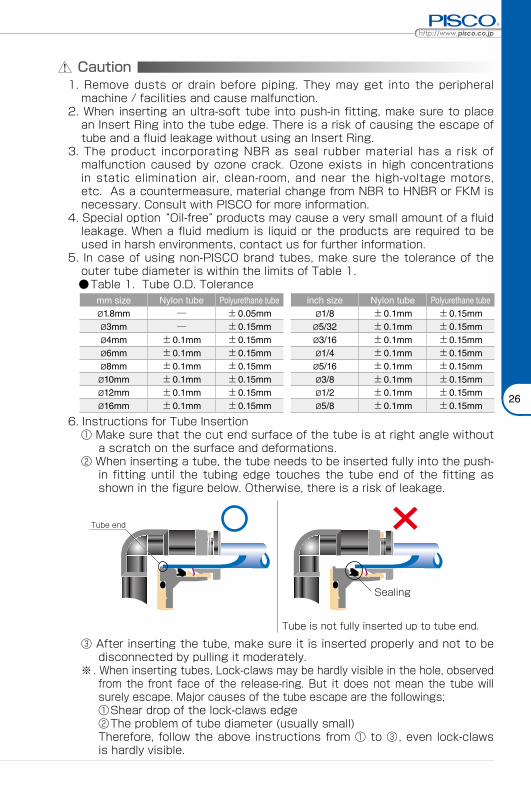
5. In case of using non-PISCO brand tubes, make sure the tolerance of the outer tube diameter is within the limits of Table 1.
●Table 1. Tube O.D. Tolerancemm size Nylon tube Polyurethane tube inch size Nylon tube Polyurethane tubeø1.8mm ─ ±0.05mm ø1/8 ±0.1mm ±0.15mmø3mm ─ ±0.15mm ø5/32 ±0.1mm ±0.15mmø4mm ±0.1mm ±0.15mm ø3/16 ±0.1mm ±0.15mmø6mm ±0.1mm ±0.15mm ø1/4 ±0.1mm ±0.15mmø8mm ±0.1mm ±0.15mm ø5/16 ±0.1mm ±0.15mmø10mm ±0.1mm ±0.15mm ø3/8 ±0.1mm ±0.15mmø12mm ±0.1mm ±0.15mm ø1/2 ±0.1mm ±0.15mmø16mm ±0.1mm ±0.15mm ø5/8 ±0.1mm ±0.15mm
6. Instructions for Tube Insertion① Make sure that the cut end surface of the tube is at right angle without
a scratch on the surface and deformations.② When inserting a tube, the tube needs to be inserted fully into the push-
in fitting until the tubing edge touches the tube end of the fitting as shown in the figure below. Otherwise, there is a risk of leakage.
Tube end
Sealing
Tube is not fully inserted up to tube end.
③ After inserting the tube, make sure it is inserted properly and not to be disconnected by pulling it moderately.
※. When inserting tubes, Lock-claws may be hardly visible in the hole, observed from the front face of the release-ring. But it does not mean the tube will surely escape. Major causes of the tube escape are the followings; ①Shear drop of the lock-claws edge②The problem of tube diameter (usually small)Therefore, follow the above instructions from ① to ③, even lock-claws is hardly visible.
27
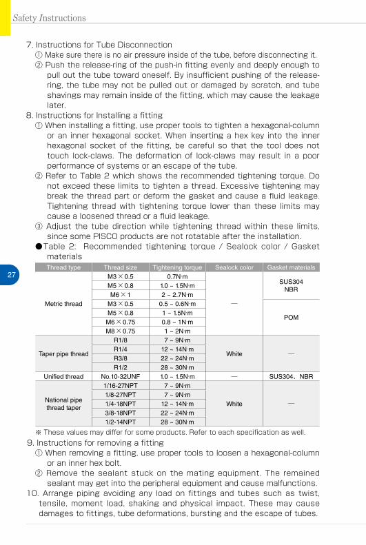
7. Instructions for Tube Disconnection① Make sure there is no air pressure inside of the tube, before disconnecting it.② Push the release-ring of the push-in fitting evenly and deeply enough to
pull out the tube toward oneself. By insufficient pushing of the release-ring, the tube may not be pulled out or damaged by scratch, and tube shavings may remain inside of the fitting, which may cause the leakage later.
8. Instructions for Installing a fitting① When installing a fitting, use proper tools to tighten a hexagonal-column
or an inner hexagonal socket. When inserting a hex key into the inner hexagonal socket of the fitting, be careful so that the tool does not touch lock-claws. The deformation of lock-claws may result in a poor performance of systems or an escape of the tube.
② Refer to Table 2 which shows the recommended tightening torque. Do not exceed these limits to tighten a thread. Excessive tightening may break the thread part or deform the gasket and cause a fluid leakage. Tightening thread with tightening torque lower than these limits may cause a loosened thread or a fluid leakage.
③ Adjust the tube direction while tightening thread within these limits, since some PISCO products are not rotatable after the installation.
●Table 2: Recommended tightening torque / Sealock color / Gasket materialsThread type Thread size Tightening torque Sealock color Gasket materials
Metric thread
M3×0.5 0.7N·m
─
SUS304NBR
M5×0.8 1.0 ~ 1.5N·mM6×1 2 ~ 2.7N·m
M3×0.5 0.5 ~ 0.6N·m
POMM5×0.8 1 ~ 1.5N·mM6×0.75 0.8 ~ 1N·mM8×0.75 1 ~ 2N·m
Taper pipe thread
R1/8 7 ~ 9N·m
White ─R1/4 12 ~ 14N·mR3/8 22 ~ 24N·mR1/2 28 ~ 30N·m
Unified thread No.10-32UNF 1.0 ~ 1.5N·m ─ SUS304、NBR
National pipe thread taper
1/16-27NPT 7 ~ 9N·m
White ─1/8-27NPT 7 ~ 9N·m1/4-18NPT 12 ~ 14N·m3/8-18NPT 22 ~ 24N·m1/2-14NPT 28 ~ 30N·m
※ These values may differ for some products. Refer to each specification as well.9. Instructions for removing a fitting
① When removing a fitting, use proper tools to loosen a hexagonal-column or an inner hex bolt.
② Remove the sealant stuck on the mating equipment. The remained sealant may get into the peripheral equipment and cause malfunctions.
10. Arrange piping avoiding any load on fittings and tubes such as twist, tensile, moment load, shaking and physical impact. These may cause damages to fittings, tube deformations, bursting and the escape of tubes.
Safety Instructions
Fitting SeriesFITTING
33
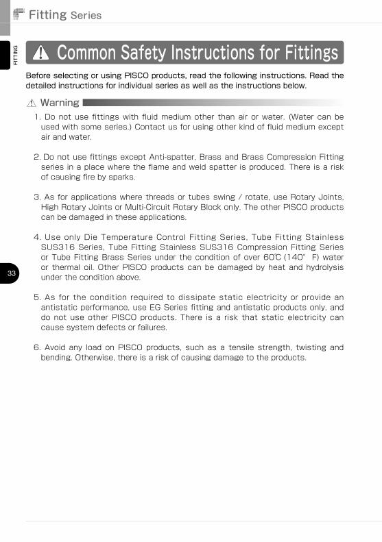
Common Safety Instructions for Fittings
Warning
Before selecting or using PISCO products, read the following instructions. Read the detailed instructions for individual series as well as the instructions below.
1.��Do�not�use� fittings�with� fluid�medium�other� than�air� or�water.� (Water� can�be�used�with�some�series.)�Contact�us�for�using�other�kind�of�fluid�medium�except�air�and�water.
2.��Do�not�use�fittings�except�Anti-spatter,�Brass�and�Brass�Compression�Fitting�series�in�a�place�where�the�flame�and�weld�spatter�is�produced.�There�is�a�risk�of�causing�fire�by�sparks.
3.��As�for�applications�where�threads�or�tubes�swing�/�rotate,�use�Rotary�Joints,�High�Rotary�Joints�or�Multi-Circuit�Rotary�Block�only.�The�other�PISCO�products�can�be�damaged�in�these�applications.
4.��Use� only�Die�Temperature�Control� Fitting�Series,� Tube� Fitting�Stainless�SUS316�Series,� Tube� Fitting�Stainless�SUS316�Compression� Fitting�Series�or�Tube�Fitting�Brass�Series�under� the�condition�of�over�60℃ (140° F)�water�or� thermal� oil.�Other�PISCO�products�can�be�damaged�by�heat�and�hydrolysis�under�the�condition�above.
5.��As� for� the� condition� required� to� dissipate� static� electricity� or� provide� an�antistatic�performance,�use�EG�Series�fitting�and�antistatic�products�only,�and�do� not� use� other�PISCO�products.� There� is� a� risk� that� static� electricity� can�cause�system�defects�or�failures.
6.��Avoid� any� load� on�PISCO�products,� such� as� a� tensile� strength,� twisting� and�bending.�Otherwise,�there�is�a�risk�of�causing�damage�to�the�products.
FITTING
TUBE
VALVE
CONTROLLER
StandardSeries
MiniSeries
StainlessSeries
ChemicalSeries
PPSeries
EGSeries
Anti-spatter& Brass Series
Die TemperatureControl
MinimalSeries
Stop FittingSeries
RotarySeries
Twist-ProofFitting
Block andConnector
Coupling
ColorCap
http://www.pisco.co.jphttp://www.pisco.co.jp
34
MAKE-TO-ORDERPRODUCTS
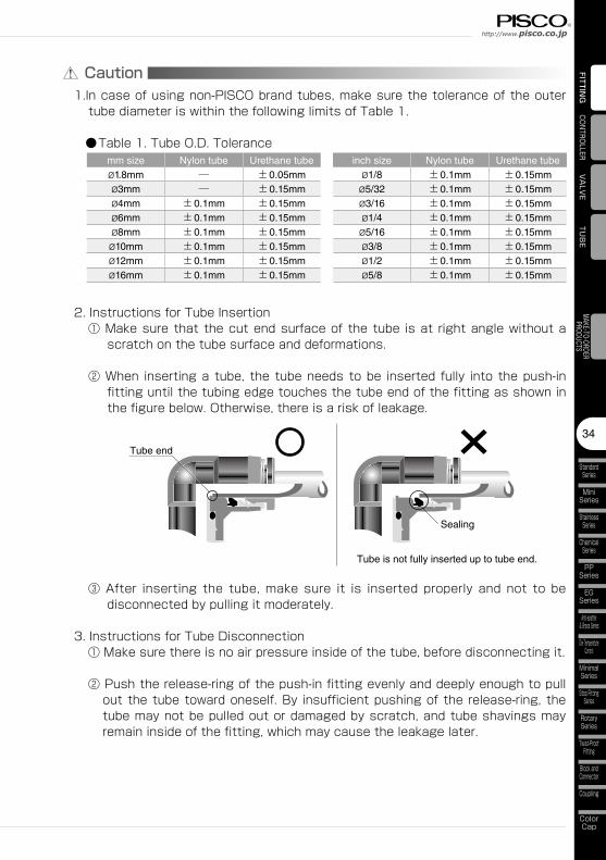
Caution1.In�case�of�using�non-PISCO�brand�tubes,�make�sure�the�tolerance�of�the�outer�tube�diameter�is�within�the�following�limits�of�Table�1.
●Table�1.�Tube�O.D.�Tolerancemm size Nylon tube Urethane tube inch size Nylon tube Urethane tubeø1.8mm ─ ±0.05mm ø1/8 ±0.1mm ±0.15mmø3mm ─ ±0.15mm ø5/32 ±0.1mm ±0.15mmø4mm ±0.1mm ±0.15mm ø3/16 ±0.1mm ±0.15mmø6mm ±0.1mm ±0.15mm ø1/4 ±0.1mm ±0.15mmø8mm ±0.1mm ±0.15mm ø5/16 ±0.1mm ±0.15mmø10mm ±0.1mm ±0.15mm ø3/8 ±0.1mm ±0.15mmø12mm ±0.1mm ±0.15mm ø1/2 ±0.1mm ±0.15mmø16mm ±0.1mm ±0.15mm ø5/8 ±0.1mm ±0.15mm
2.�Instructions�for�Tube�Insertion①�Make�sure�that�the�cut�end�surface�of�the�tube� is�at� right�angle�without�a�scratch�on�the�tube�surface�and�deformations.
②�When� inserting�a�tube,� the�tube�needs�to�be� inserted� fully� into�the�push-in�fitting�until�the�tubing�edge�touches�the�tube�end�of�the�fitting�as�shown�in�the�figure�below.�Otherwise,�there�is�a�risk�of�leakage.
Tube end
Sealing
Tube is not fully inserted up to tube end.
③�After� inserting� the� tube,�make� sure� it� is� inserted� properly� and� not� to� be�disconnected�by�pulling�it�moderately.
3.�Instructions�for�Tube�Disconnection①�Make�sure�there�is�no�air�pressure�inside�of�the�tube,�before�disconnecting�it.
②�Push�the�release-ring�of�the�push-in�fitting�evenly�and�deeply�enough�to�pull�out�the�tube�toward�oneself.�By� insufficient�pushing�of�the�release-ring,�the�tube�may�not�be�pulled�out�or�damaged�by�scratch,�and�tube�shavings�may�remain�inside�of�the�fitting,�which�may�cause�the�leakage�later.
Fitting SeriesFITTING
35
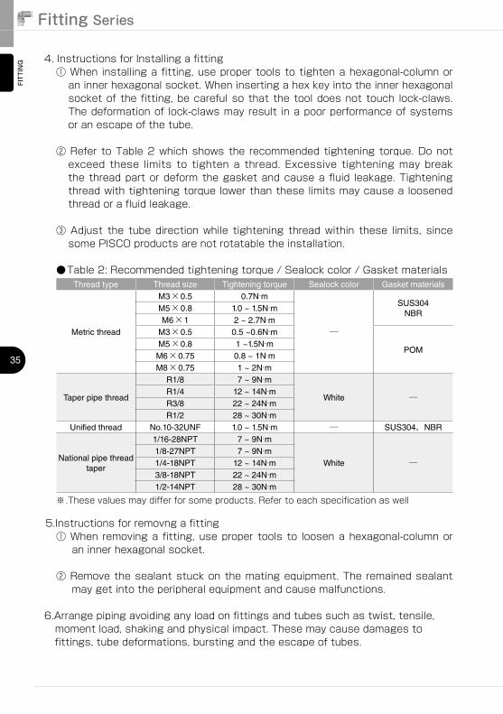
5.Instructions�for�removng�a�fitting①�When�removing�a� fitting,�use�proper�tools�to� loosen�a�hexagonal-column�or�an�inner�hexagonal�socket.
②�Remove�the�sealant�stuck�on�the�mating�equipment.�The�remained�sealant�may�get�into�the�peripheral�equipment�and�cause�malfunctions.
6.Arrange�piping�avoiding�any�load�on�fittings�and�tubes�such�as�twist,�tensile,�moment�load,�shaking�and�physical�impact.�These�may�cause�damages�to�fittings,�tube�deformations,�bursting�and�the�escape�of�tubes.
4.�Instructions�for�Installing�a�fitting①�When�installing�a�fitting,�use�proper�tools�to�tighten�a�hexagonal-column�or�an�inner�hexagonal�socket.�When�inserting�a�hex�key�into�the�inner�hexagonal�socket�of�the�fitting,�be�careful�so�that�the�tool�does�not�touch� lock-claws.�The�deformation�of� lock-claws�may�result� in�a�poor�performance�of�systems�or�an�escape�of�the�tube.
②�Refer�to�Table�2�which�shows�the� recommended�tightening�torque.�Do�not�exceed� these� limits� to� tighten� a� thread.� Excessive� tightening�may� break�the�thread�part�or�deform�the�gasket�and�cause�a�fluid� leakage.�Tightening�thread�with�tightening�torque�lower�than�these�limits�may�cause�a�loosened�thread�or�a�fluid�leakage.
③�Adjust� the� tube�direction�while� tightening� thread�within� these� limits,� since�some�PISCO�products�are�not�rotatable�the�installation.
●Table�2:�Recommended�tightening�torque�/�Sealock�color�/�Gasket�materialsThread type Thread size Tightening torque Sealock color Gasket materials
Metric thread
M3×0.5 0.7N·m
─
SUS304NBR
M5×0.8 1.0 ~ 1.5N·mM6×1 2 ~ 2.7N·m
M3×0.5 0.5 ~0.6N·m
POMM5×0.8 1 ~1.5N·mM6×0.75 0.8 ~ 1N·mM8×0.75 1 ~ 2N·m
Taper pipe thread
R1/8 7 ~ 9N·m
White ─R1/4 12 ~ 14N·mR3/8 22 ~ 24N·mR1/2 28 ~ 30N·m
Unified thread No.10-32UNF 1.0 ~ 1.5N·m ─ SUS304、NBR
National pipe thread taper
1/16-28NPT 7 ~ 9N·m
White ─1/8-27NPT 7 ~ 9N·m1/4-18NPT 12 ~ 14N·m3/8-18NPT 22 ~ 24N·m1/2-14NPT 28 ~ 30N·m
※.These�values�may�differ�for�some�products.�Refer�to�each�specification�as�well
Top Related