


Languages
Pages
Legal

J. PIVARČ
stone columns – determination of the soil improvement factor
KeY Words
• Stone column,• design,• laboratory model,• numerical model.
aBstract
A stone column is one of the soil stabilizing methods that is used to increase strength, decrease the compressibility of soft and loose fine graded soils, accelerate a consolidation effect and reduce the liquefaction potential of soils. The columns consist of compacted gravel or crushed stone arranged by a vibrator. This paper deals with Priebe`s theory (1976) on the design of an improvement factor, which belongs among the most used analytical methods and also describes the numerical and laboratory models of stone columns. The improvement factors calculated from numerical and laboratory models are compared with the improvement factors resulting from Priebe´s theory.
Ján PIVARČ[email protected]:stonecolumns
Address:DepartmentofGeotechnics,FacultyofCivilEngineeringSlovakUniversityofTechnology,Radlinského11,81368Bratislava
Vol. XIX, 2011, No. 3, 17 – 21
introduction
Vast areas coveredwith thick layersof fillsorwith layersof softclaydepositsarenot suitable for theconstructionofafoundation.With the increasing size of urban areas and industrial zones it isnecessary to consider the possibilities of realizing foundationson these areas. Ground improvement techniques are normallypreferred for economic considerations. Out of several techniquesavailable, stone columns belong among the most preferable andare also widely used. This ground improvement technique hasbeen successfully used to increase bearing capacity and reducethe settlement of constructions such as storage tanks, earthenembankments, raft foundations, etc. Their main advantage lies inimprovingthesoilpropertiesbelowastructure(raftanddepth)andfollowingthereductionofanirregularsettlement.In spite of thewide use of stone columns and their developmentin construction methods, present design methods are empirical,and only limited information about designing stone columns areavailableintechnicalcodes.
The stone column technique was adopted in European countriesin the early 1960s. Stone columns in compressive loads failin2 main different modes: bulging (Hughes and Withers, 1974)[1] and general shear failure (Barksdale and Bachus, 1983) [2].McKelvey, et al. (2004) [3] carried out experimental studies onagroupoffivestonecolumnsandreportedthatthecentralcolumndeformed or bulged uniformly, while the edge columns bulgedaway from the neighboring columns. Many researchers havedevelopedtheoreticalsolutionsforestimating thebearingcapacityand settlement of foundations reinforced with stone columns.Priebe (1995) [4]proposedamethodforestimating thesettlementof foundations resting on an infinite grid of stone columns. Thebasicforthismethodistheunitcellconcept.Inthisconcept,Priebeconsideredtheareaofsoilsurroundingastonecolumnatadistancedepending on the spacing of the columns.As all the columns aresimultaneouslyloaded,itisassumedthatalateraldeformationinthesoilattheboundaryoftheunitcellisequaltozero.Thesettlementimprovementfactorisderivedasafunctionofthearearatioofthewholeunitcellandstonecolumnsandtheangleofinternalfriction
2011 slovaK universitY of technoloGY 17

18 stone columns – determination of the soil improvement factor
2011/3 PAGES 17 — 21
ofthecolumnmaterial.Withtheexceptionoftheareaneartheedgesof theloadedarea, thebehaviorof thestonecolumnsis thesame;thus,onlyonecolumnunitneedstobeanalyzed.Thisstudyisfocusedonacomparisonofnumerical,analyticalandlaboratorymodelsettlementstoestimatetheimprovementfactorofsoilimprovedbystonecolumns.Allthemodelsinthisstudywerepreparedbythevibroreplacementmethod,whichmeansthatsoilisremovedfromaholeandnotcompactedtothesidessuchasinthevibrodisplacementmethod.
laBoratorY model
The laboratory experimentswere carried out using stone columnswithdiametersof about60mmand lenghtsof300mm,420mmand540mm.All the laboratoryexperimentswereperformedwithstone columns surrounded by clayey sand, S5–SC according toSTN 73 1001, incylindrical test boxes with aheight of 600 mmandwithvariable inner diameters from 125mm to 253mm.Thecylindical boxes represent the required area of aunit cell aroundastone column.Atriangular pattern of stone columns was underconsideration.Testingofthestonecolumnswascarriedoutwithsoilparametresacquiredfromlaboratorytestsofsamplesremovedfromthe cylindrical test boxes after compaction of the soil. The stonecolumnsweremodeledasafloatingunitinthesoilspace;thatis,thebottompartofthelongestcolumnisabout1d,or,about60mmfromthebottomofthetestbox.Becausethestonecolumnhasrelativelylessstiffnessincomparisontoaconventionalpileandalsobecauseahorizontal deformation ismore expected than avertical one, thedistanceofthestonecolumnofabout60mmfromthebottomofthetestboxisadequate.Theratiosofthelengthofthestonecolumnstothediameterofthestonecolumnsl/daremodeledas5,7and9.ThetestwascarriedoutinatestboxfilledwithclayeysandS5–SCwithatotalcohesioncu=16kPa.Thehumidityof thesoil in theboxwassetbeforetesting,soanappropriatequantityofcleanwaterwaspoured intodry soil.Every experimentwas realizedwith thesamehumidityofsoilofabout16%.All thesampleswereleftforat least24hours forsaturationbeforeputting theminto theboxesandcompactingandformingthestonecolumn(fig.1,2).Thestonecolumnswereformedfromgravel,whichwasclassifiedaccordingtheSTN73101asG2–GP.Thefractionsofthegravelwerefrom2mmto5mm.Allthesoilandgravelpropertiesareseenintable1.
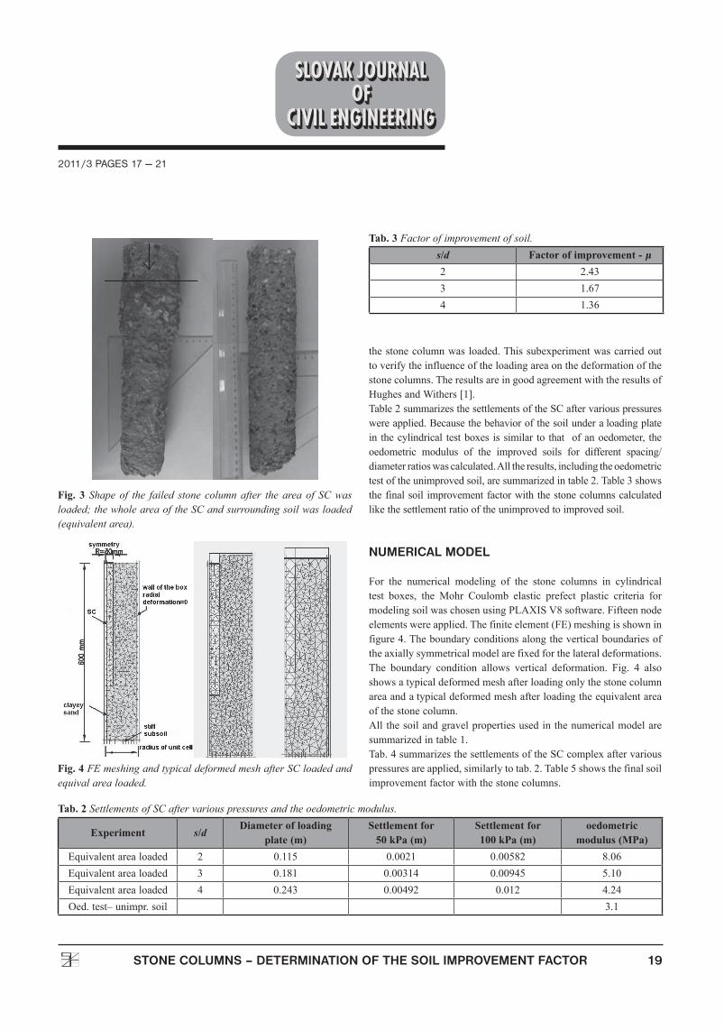
After theformationof thestonecolumns, the“load–settlement“behavior of the improved complexwas observed.Arigid 10mmthick steel plate was used as aloading plate. The loading wasappliedbyacompactorwithaconstantvelocityof5mm/min.Thus,the increased force and deformationwere observed by electronicsensorsatintervalsof1sec.Theleftsideoffigure3showsthefinalshapeof the stone columnwhen thewhole complexof the stonecolumnandsurroundingsoilwasloaded.Ontherightsidethefinalshapeofthecolumnisdeformedbybulgingwhenonlythatareaof
Tab. 1 Properties of materials used in the experiments.Material w (%) Edef (MPa) μ cu (kPa) φ (˚) γd,max (kN/ m3) γ (kN/ m3)S5-SC 16 3.1 0.35 16 24 16.01 14.97G2-GP 0 45 0.2 0 45 17.36 16.52
Fig. 1 Compacting of soil prepared for the formation of the stone columns.
Fig. 2 Installing a stone column into the soil and a compacted stone column.
2011/3 PAGES 17 — 21
19stone columns – determination of the soil improvement factor
thestonecolumnwasloaded.Thissubexperimentwascarriedouttoverifytheinfluenceoftheloadingareaonthedeformationofthestonecolumns.TheresultsareingoodagreementwiththeresultsofHughesandWithers[1].Table2summarizesthesettlementsoftheSCaftervariouspressureswereapplied.Becausethebehaviorofthesoilunderaloadingplatein thecylindrical testboxes is similar to that ofanoedometer, theoedometric modulus of the improved soils for different spacing/diameterratioswascalculated.Alltheresults,includingtheoedometrictestoftheunimprovedsoil,aresummarizedintable2.Table3showsthefinalsoil improvementfactorwiththestonecolumnscalculatedlikethesettlementratiooftheunimprovedtoimprovedsoil.
numerical model
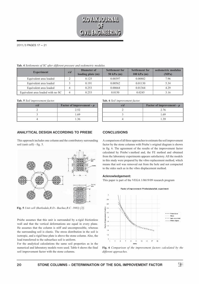
For the numerical modeling of the stone columns in cylindricaltest boxes, the Mohr Coulomb elastic prefect plastic criteria formodelingsoilwaschosenusingPLAXISV8software.Fifteennodeelementswereapplied.Thefiniteelement(FE)meshingisshowninfigure4.Theboundaryconditionsalongtheverticalboundariesoftheaxiallysymmetricalmodelarefixedforthelateraldeformations.The boundary condition allows vertical deformation. Fig. 4 alsoshowsatypicaldeformedmeshafterloadingonlythestonecolumnareaandatypicaldeformedmeshafterloadingtheequivalentareaofthestonecolumn.Allthesoilandgravelpropertiesusedinthenumericalmodelaresummarizedintable1.Tab.4summarizesthesettlementsoftheSCcomplexaftervariouspressuresareapplied,similarlytotab.2.Table5showsthefinalsoilimprovementfactorwiththestonecolumns.
Tab. 2 Settlements of SC after various pressures and the oedometric modulus.
Experiment s/dDiameter of loading
plate (m)Settlement for
50 kPa (m)Settlement for 100 kPa (m)
oedometric modulus (MPa)
Equivalentarealoaded 2 0.115 0.0021 0.00582 8.06Equivalentarealoaded 3 0.181 0.00314 0.00945 5.10Equivalentarealoaded 4 0.243 0.00492 0.012 4.24Oed.test–unimpr.soil 3.1
Tab. 3 Factor of improvement of soil.s/d Factor of improvement - μ2 2.433 1.674 1.36
Fig. 3 Shape of the failed stone column after the area of SC was loaded; the whole area of the SC and surrounding soil was loaded (equivalent area).
Fig. 4 FE meshing and typical deformed mesh after SC loaded and equival area loaded.
20 stone columns – determination of the soil improvement factor
2011/3 PAGES 17 — 21
analYtical desiGn accordinG to prieBe
Thisapproachincludesonecolumnandthecontributorysurroundingsoil(unitcell)-fig.5.
Priebe assumes that this unit is surrounded by arigid frictionlesswall and that the vertical deformations are equal in every plane.He assumes that the column is stiff and uncompressible,whereasthesurroundingsoil iselastic.Thestressdistributionin thesoil isisotropic,andarigidbaseplateisabovethestonecolumn.Also,theloadtransferredtothesubsurfacesoilisuniform.For the analytical calculations the same soil properties as in thenumericalandlaboratorymodelswereused.Table6showsthefinalsoilimprovementfactorwiththestonecolumns.
conclusions
AcomparisonofallthreeapproachestoestimatethesoilimprovementfactorbythestonecolumnswithPriebe´soriginaldiagramisshownin fig. 6.The agreement of the results of the improvement factorcalculated by Priebe`smethod and, the FE method and obtainedfromthelaboratoryexperimentsappearssatisfactory.Allthemodelsinthisstudywerepreparedbythevibroreplacementmethod,whichmeansthatsoilwasremovedoutfromtheholeandnotcompactedtothesidessuchasinthevibrodisplacementmethod.
acknowledgement: ThispaperispartoftheVEGA1/0619/09researchprogram
Tab. 5 Soil improvement factor.s/d Factor of improvement - μ2 2.523 1.694 1.36
Tab. 6 Soil improvement factor.s/d Factor of improvement - μ2 2.763 1.694 1.39
Tab. 4 Settlements of SC after different pressure and oedometric modulus.
Experiment s/dDiameter of
loading plate (m)Settlement for
50 kPa (m)Settlement for 100 kPa (m)
oedometric modulus (MPa)
Equivalentarealoaded 2 0.125 0.00397 0.00802 7.96Equivalentarealoaded 3 0.191 0.00562 0.01130 5.34Equivalentarealoaded 4 0.253 0.00664 0.01364 4.29
EquivalentarealoadedwithnoSC 4 0.253 0.0150 0.0245 3.16
Fig. 5 Unit cell (Barksdale,R.D.- Bachus,R.C. 1983) [2].
Fig. 6 Comparison of the improvement factors calculated by the different approaches.
2011/3 PAGES 17 — 21
21stone columns – determination of the soil improvement factor
REFERENCES
[1] Hughes,J.M.,Withers,N.J.:Reinforcingofsoftcohesivesoilswithstonecolumns,1974.
[2] Barksdale,R.D.,Bachus,R.C.:Designandconstructionofstonecolumns,1983.
[3]Mckelvey,D.,Sivakumar,V.,Bell,A.,Graham, J.:Modellingvibratedstonecolumnsinsoftclay,2004.
[4] Priebeh,J.:TheDesignofVibroReplacement,1995.
Top Related