


Languages
Pages
Legal

Handpiece Parts & Products Star Titan 5,000 RPM (Early Model)
STEP
1Preparation for Repair
1) Remove Nose Cone2) Remove handpiece from air supply3) Remove Gasket {HHX4HG}
Gasket Inspection: Examine gasket for obvious wear, tearing or disfigurement. Ifany of these conditions exist, replace.
STEP
2Seperate Body from Backend
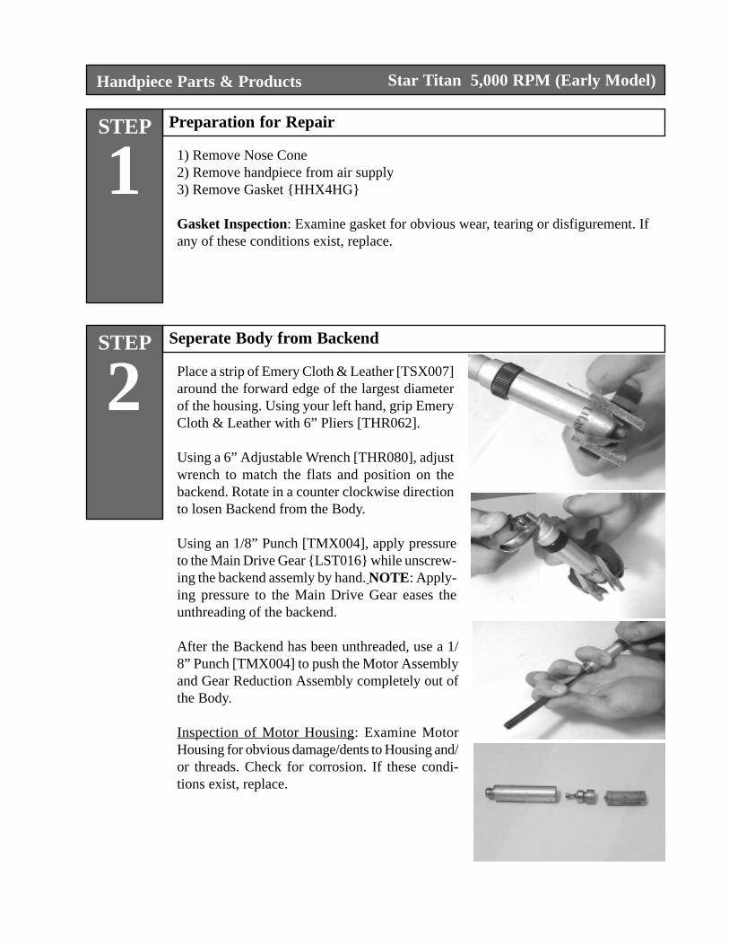
Place a strip of Emery Cloth & Leather [TSX007]around the forward edge of the largest diameterof the housing. Using your left hand, grip EmeryCloth & Leather with 6” Pliers [THR062].
Using a 6” Adjustable Wrench [THR080], adjustwrench to match the flats and position on thebackend. Rotate in a counter clockwise directionto losen Backend from the Body.
Using an 1/8” Punch [TMX004], apply pressureto the Main Drive Gear {LST016} while unscrew-ing the backend assemly by hand. NOTE: Apply-ing pressure to the Main Drive Gear eases theunthreading of the backend.
After the Backend has been unthreaded, use a 1/8” Punch [TMX004] to push the Motor Assemblyand Gear Reduction Assembly completely out ofthe Body.
Inspection of Motor Housing: Examine MotorHousing for obvious damage/dents to Housing and/or threads. Check for corrosion. If these condi-tions exist, replace.
Handpiece Parts & Products Star Titan 5,000 RPM (Early Model)
STEP
3Disassembly of Backend
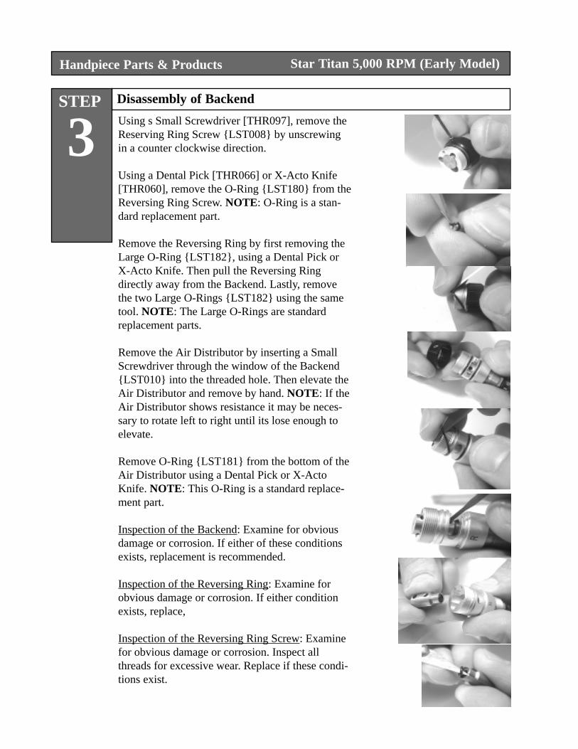
Using s Small Screwdriver [THR097], remove theReserving Ring Screw {LST008} by unscrewingin a counter clockwise direction.
Using a Dental Pick [THR066] or X-Acto Knife[THR060], remove the O-Ring {LST180} from theReversing Ring Screw. NOTE: O-Ring is a stan-dard replacement part.
Remove the Reversing Ring by first removing theLarge O-Ring {LST182}, using a Dental Pick orX-Acto Knife. Then pull the Reversing Ringdirectly away from the Backend. Lastly, removethe two Large O-Rings {LST182} using the sametool. NOTE: The Large O-Rings are standardreplacement parts.
Remove the Air Distributor by inserting a SmallScrewdriver through the window of the Backend{LST010} into the threaded hole. Then elevate theAir Distributor and remove by hand. NOTE: If theAir Distributor shows resistance it may be neces-sary to rotate left to right until its lose enough toelevate.
Remove O-Ring {LST181} from the bottom of theAir Distributor using a Dental Pick or X-ActoKnife. NOTE: This O-Ring is a standard replace-ment part.
Inspection of the Backend: Examine for obviousdamage or corrosion. If either of these conditionsexists, replacement is recommended.
Inspection of the Reversing Ring: Examine forobvious damage or corrosion. If either conditionexists, replace,
Inspection of the Reversing Ring Screw: Examinefor obvious damage or corrosion. Inspect allthreads for excessive wear. Replace if these condi-tions exist.
Handpiece Parts & Products
STEP
4Removal of Distributor Plate & Alignment Pin
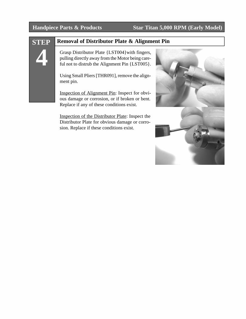
Grasp Distributor Plate {LST004}with fingers,pulling directly away from the Motor being care-ful not to distrub the Alignment Pin {LST005}.
Using Small Pliers [THR091], remove the align-ment pin.
Inspection of Alignment Pin: Inspect for obvi-ous damage or corrosion, or if broken or bent.Replace if any of these conditions exist.
Inspection of the Distributor Plate: Inspect theDistributor Plate for obvious damage or corro-sion. Replace if these conditions exist.
Star Titan 5,000 RPM (Early Model)
Handpiece Parts & Products
STEP
5Remove Rear Bearing Carrier
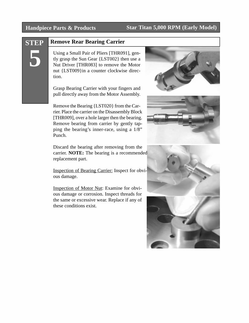
Using a Small Pair of Pliers [THR091], gen-tly grasp the Sun Gear {LST002} then use aNut Driver [THR083] to remove the Motornut {LST009}in a counter clockwise direc-tion.
Grasp Bearing Carrier with your fingers andpull directly away from the Motor Assembly.
Remove the Bearing {LST020} from the Car-rier. Place the carrier on the Disassembly Block[THR009], over a hole larger then the bearing.Remove bearing from carrier by gently tap-ping the bearing’s inner-race, using a 1/8”Punch.
Discard the bearing after removing from thecarrier. NOTE: The bearing is a recommendedreplacement part.
Inspection of Bearing Carrier: Inspect for obvi-ous damage.
Inspection of Motor Nut: Examine for obvi-ous damage or corrosion. Inspect threads forthe same or excessive wear. Replace if any ofthese conditions exist.
Star Titan 5,000 RPM (Early Model)
Handpiece Parts & Products
STEP
6Remove Motor Housing, Blades & Spring
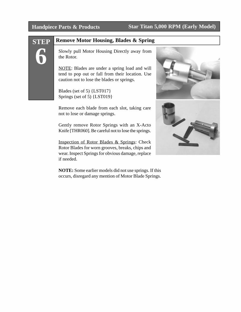
Slowly pull Motor Housing Directly away fromthe Rotor.
NOTE: Blades are under a spring load and willtend to pop out or fall from their location. Usecaution not to lose the blades or springs.
Blades (set of 5) {LST017}Springs (set of 5) {LST019}
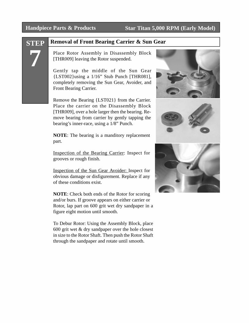
Remove each blade from each slot, taking carenot to lose or damage springs.
Gently remove Rotor Springs with an X-ActoKnife [THR060]. Be careful not to lose the springs.
Inspection of Rotor Blades & Springs: CheckRotor Blades for worn grooves, breaks, chips andwear. Inspect Springs for obvious damage, replaceif needed.
NOTE: Some earlier models did not use springs. If thisoccurs, disregard any mention of Motor Blade Springs.
Star Titan 5,000 RPM (Early Model)
Handpiece Parts & Products
STEP
7Removal of Front Bearing Carrier & Sun Gear
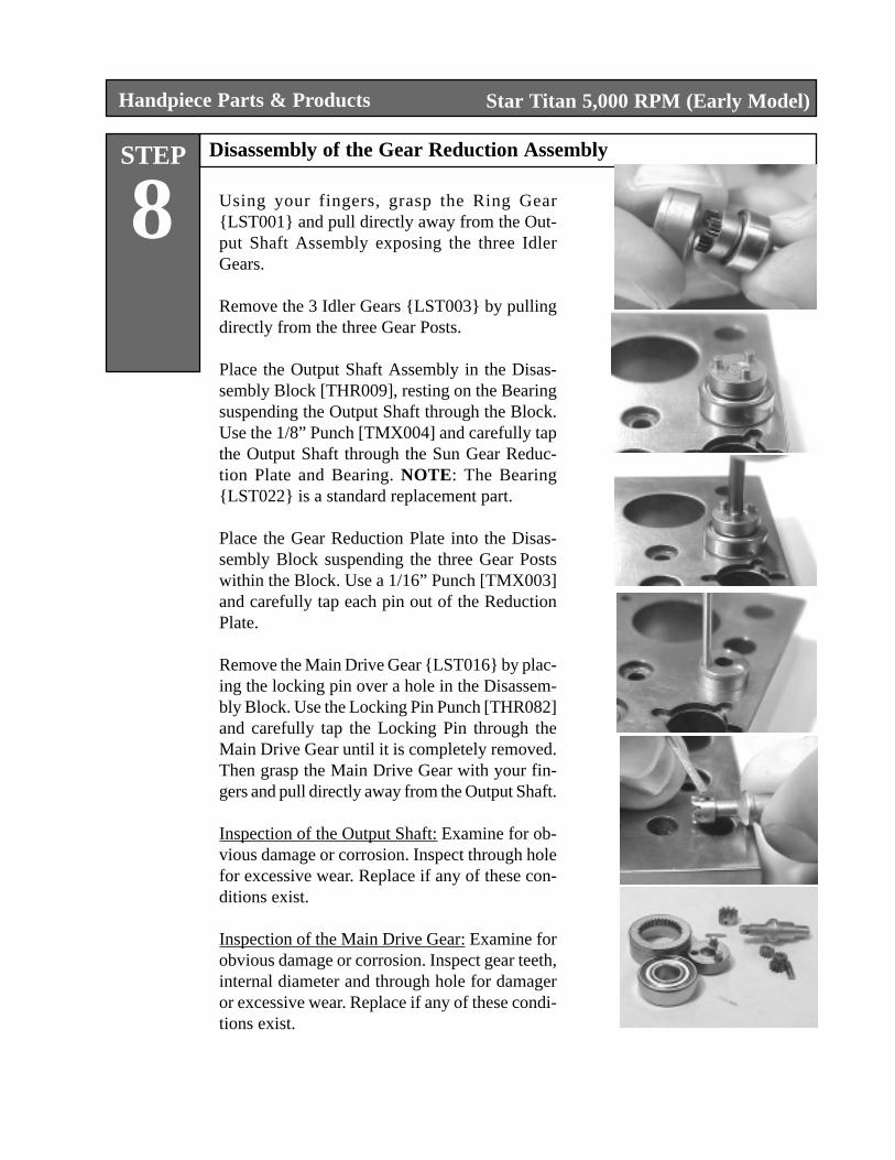
Place Rotor Assembly in Disassembly Block[THR009] leaving the Rotor suspended.
Gently tap the middle of the Sun Gear{LST002}using a 1/16” Stub Punch [THR081],completely removing the Sun Gear, Avoider, andFront Bearing Carrier.
Remove the Bearing {LST021} from the Carrier.Place the carrier on the Disassembly Block[THR009], over a hole larger then the bearing. Re-move bearing from carrier by gently tapping thebearing’s inner-race, using a 1/8” Punch.
NOTE: The bearing is a manditory replacementpart.
Inspection of the Bearing Carrier: Inspect forgrooves or rough finish.
Inspection of the Sun Gear Avoider: Inspect forobvious damage or disfigurement. Replace if anyof these conditions exist.
NOTE: Check both ends of the Rotor for scoringand/or burs. If groove appears on either carrier orRotor, lap part on 600 grit wet dry sandpaper in afigure eight motion until smooth.
To Debur Rotor: Using the Assembly Block, place600 grit wet & dry sandpaper over the hole closestin size to the Rotor Shaft. Then push the Rotor Shaftthrough the sandpaper and rotate until smooth.
Star Titan 5,000 RPM (Early Model)
Handpiece Parts & Products
STEP
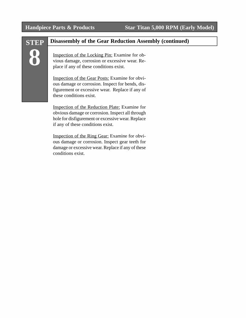
8 Using your fingers, grasp the Ring Gear{LST001} and pull directly away from the Out-put Shaft Assembly exposing the three IdlerGears.
Remove the 3 Idler Gears {LST003} by pullingdirectly from the three Gear Posts.
Place the Output Shaft Assembly in the Disas-sembly Block [THR009], resting on the Bearingsuspending the Output Shaft through the Block.Use the 1/8” Punch [TMX004] and carefully tapthe Output Shaft through the Sun Gear Reduc-tion Plate and Bearing. NOTE: The Bearing{LST022} is a standard replacement part.
Place the Gear Reduction Plate into the Disas-sembly Block suspending the three Gear Postswithin the Block. Use a 1/16” Punch [TMX003]and carefully tap each pin out of the ReductionPlate.
Remove the Main Drive Gear {LST016} by plac-ing the locking pin over a hole in the Disassem-bly Block. Use the Locking Pin Punch [THR082]and carefully tap the Locking Pin through theMain Drive Gear until it is completely removed.Then grasp the Main Drive Gear with your fin-gers and pull directly away from the Output Shaft.
Inspection of the Output Shaft: Examine for ob-vious damage or corrosion. Inspect through holefor excessive wear. Replace if any of these con-ditions exist.
Inspection of the Main Drive Gear: Examine forobvious damage or corrosion. Inspect gear teeth,internal diameter and through hole for damageror excessive wear. Replace if any of these condi-tions exist.
Disassembly of the Gear Reduction Assembly
Star Titan 5,000 RPM (Early Model)
Handpiece Parts & Products
STEP
8 Inspection of the Locking Pin: Examine for ob-vious damage, corrosion or excessive wear. Re-place if any of these conditions exist.
Inspection of the Gear Posts: Examine for obvi-ous damage or corrosion. Inspect for bends, dis-figurement or excessive wear. Replace if any ofthese conditions exist.
Inspection of the Reduction Plate: Examine forobvious damage or corrosion. Inspect all throughhole for disfigurement or excessive wear. Replaceif any of these conditions exist.
Inspection of the Ring Gear: Examine for obvi-ous damage or corrosion. Inspect gear teeth fordamage or excessive wear. Replace if any of theseconditions exist.
Disassembly of the Gear Reduction Assembly (continued)
Star Titan 5,000 RPM (Early Model)
STEP
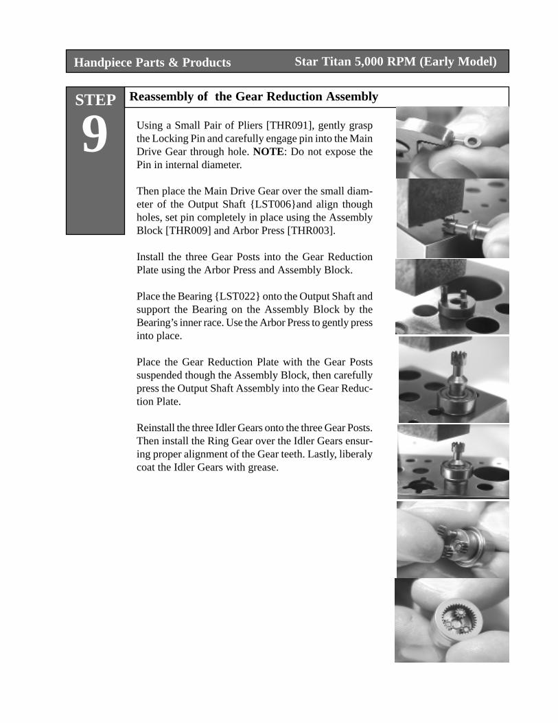
9Reassembly of the Gear Reduction Assembly
Using a Small Pair of Pliers [THR091], gently graspthe Locking Pin and carefully engage pin into the MainDrive Gear through hole. NOTE: Do not expose thePin in internal diameter.
Then place the Main Drive Gear over the small diam-eter of the Output Shaft {LST006}and align thoughholes, set pin completely in place using the AssemblyBlock [THR009] and Arbor Press [THR003].
Install the three Gear Posts into the Gear ReductionPlate using the Arbor Press and Assembly Block.
Place the Bearing {LST022} onto the Output Shaft andsupport the Bearing on the Assembly Block by theBearing’s inner race. Use the Arbor Press to gently pressinto place.
Place the Gear Reduction Plate with the Gear Postssuspended though the Assembly Block, then carefullypress the Output Shaft Assembly into the Gear Reduc-tion Plate.
Reinstall the three Idler Gears onto the three Gear Posts.Then install the Ring Gear over the Idler Gears ensur-ing proper alignment of the Gear teeth. Lastly, liberalycoat the Idler Gears with grease.
Handpiece Parts & Products Star Titan 5,000 RPM (Early Model)
Handpiece Parts & Products
STEP
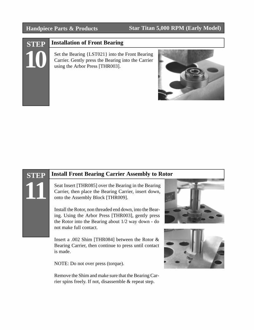
10Installation of Front Bearing
Set the Bearing {LST021} into the Front BearingCarrier. Gently press the Bearing into the Carrierusing the Arbor Press [THR003].
STEP
11Install Front Bearing Carrier Assembly to Rotor
Seat Insert [THR085] over the Bearing in the BearingCarrier, then place the Bearing Carrier, insert down,onto the Assembly Block [THR009].
Install the Rotor, non threaded end down, into the Bear-ing. Using the Arbor Press [THR003], gently pressthe Rotor into the Bearing about 1/2 way down - donot make full contact.
Insert a .002 Shim [THR084] between the Rotor &Bearing Carrier, then continue to press until contactis made.
NOTE: Do not over press (torque).
Remove the Shim and make sure that the Bearing Car-rier spins freely. If not, disassemble & repeat step.
Star Titan 5,000 RPM (Early Model)
STEP
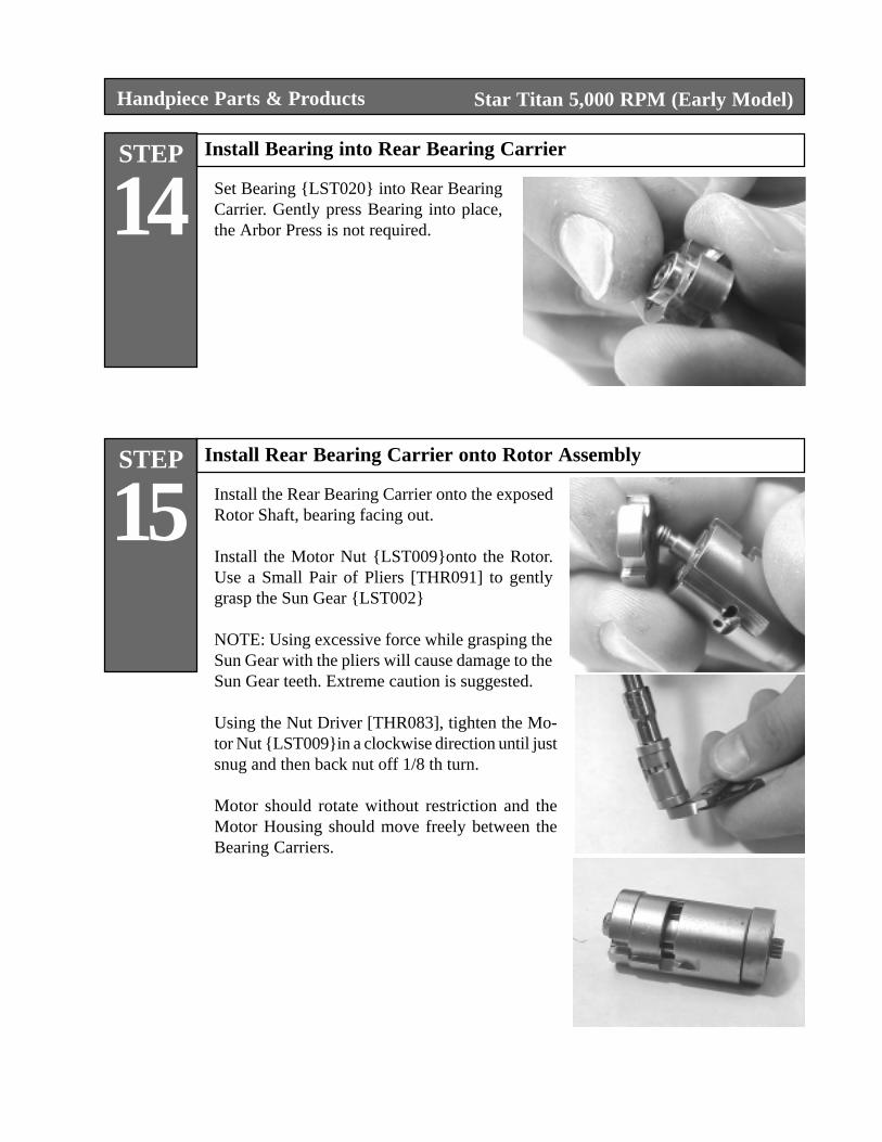
14Install Bearing into Rear Bearing Carrier
Set Bearing {LST020} into Rear BearingCarrier. Gently press Bearing into place,the Arbor Press is not required.
Handpiece Parts & Products
STEP
15Install Rear Bearing Carrier onto Rotor Assembly
Install the Rear Bearing Carrier onto the exposedRotor Shaft, bearing facing out.
Install the Motor Nut {LST009}onto the Rotor.Use a Small Pair of Pliers [THR091] to gentlygrasp the Sun Gear {LST002}
NOTE: Using excessive force while grasping theSun Gear with the pliers will cause damage to theSun Gear teeth. Extreme caution is suggested.
Using the Nut Driver [THR083], tighten the Mo-tor Nut {LST009}in a clockwise direction until justsnug and then back nut off 1/8 th turn.
Motor should rotate without restriction and theMotor Housing should move freely between theBearing Carriers.
Star Titan 5,000 RPM (Early Model)
Handpiece Parts & Products
STEP
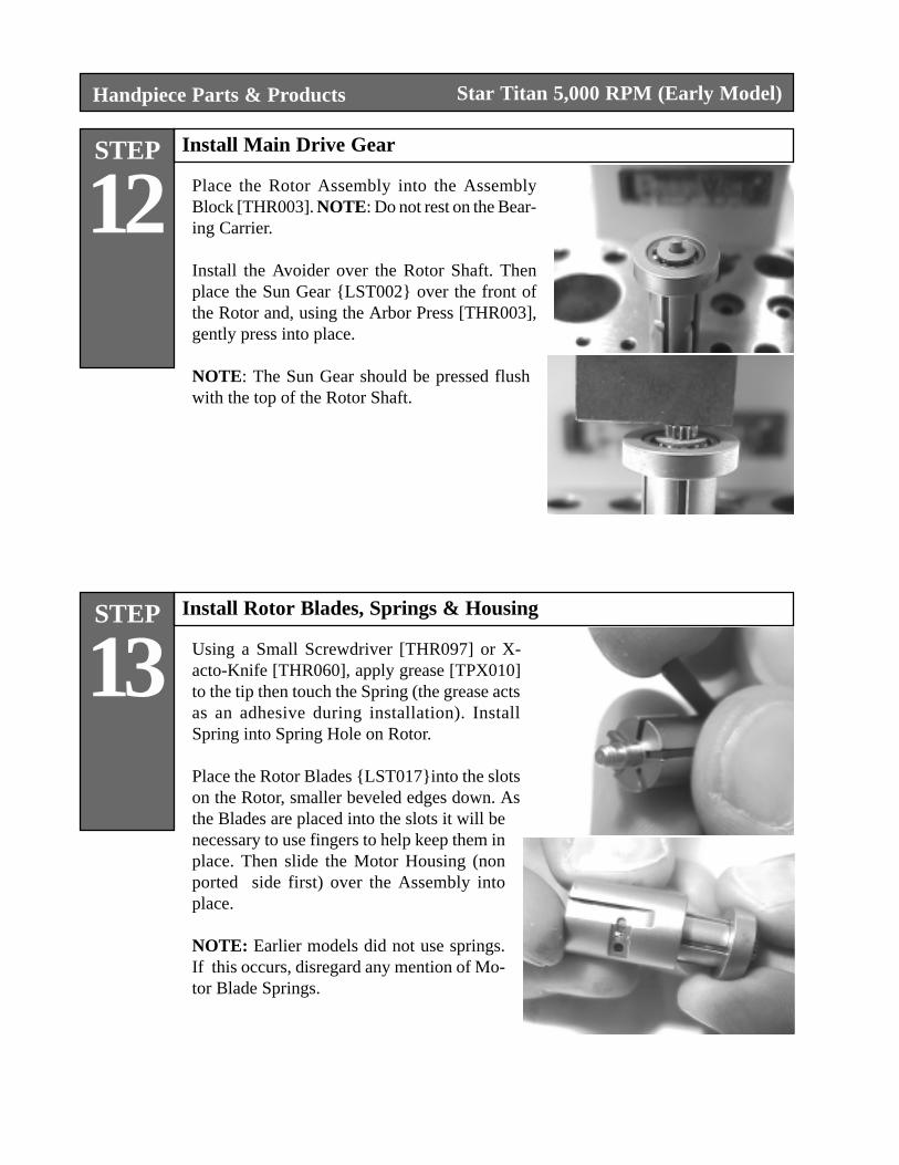
12Install Main Drive Gear
Place the Rotor Assembly into the AssemblyBlock [THR003]. NOTE: Do not rest on the Bear-ing Carrier.
Install the Avoider over the Rotor Shaft. Thenplace the Sun Gear {LST002} over the front ofthe Rotor and, using the Arbor Press [THR003],gently press into place.
NOTE: The Sun Gear should be pressed flushwith the top of the Rotor Shaft.
STEP
13Install Rotor Blades, Springs & Housing
Using a Small Screwdriver [THR097] or X-acto-Knife [THR060], apply grease [TPX010]to the tip then touch the Spring (the grease actsas an adhesive during installation). InstallSpring into Spring Hole on Rotor.
Place the Rotor Blades {LST017}into the slotson the Rotor, smaller beveled edges down. Asthe Blades are placed into the slots it will benecessary to use fingers to help keep them inplace. Then slide the Motor Housing (nonported side first) over the Assembly intoplace.
NOTE: Earlier models did not use springs.If this occurs, disregard any mention of Mo-tor Blade Springs.
Star Titan 5,000 RPM (Early Model)
STEP
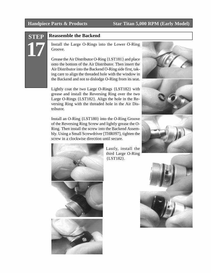
17Reassemble the Backend
Install the Large O-Rings into the Lower O-RingGroove.
Grease the Air Distributor O-Ring {LST181} and placeonto the bottom of the Air Distributor. Then insert theAir Distributor into the Backend O-Ring side first, tak-ing care to align the threaded hole with the window inthe Backend and not to dislodge O-Ring from its seat.
Lightly coat the two Large O-Rings {LST182} withgrease and install the Reversing Ring over the twoLarge O-Rings {LST182}. Align the hole in the Re-versing Ring with the threaded hole in the Air Dis-tributor.
Install an O-Ring {LST180} into the O-Ring Grooveof the Reversing Ring Screw and lightly grease the O-Ring. Then install the screw into the Backend Assem-bly. Using a Small Screwdriver [THR097], tighten thescrew in a clockwise direction until secure.
Lastly, install thethird Large O-Ring{LST182}.
Handpiece Parts & Products Star Titan 5,000 RPM (Early Model)
STEP
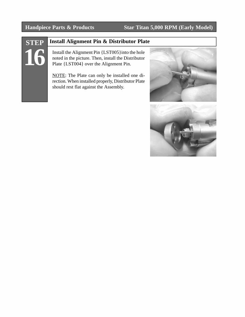
16Install Alignment Pin & Distributor Plate
Install the Alignment Pin {LST005}into the holenoted in the picture. Then, install the DistributorPlate {LST004} over the Alignment Pin.
NOTE: The Plate can only be installed one di-rection. When installed properly, Distributor Plateshould rest flat against the Assembly.
Handpiece Parts & Products Star Titan 5,000 RPM (Early Model)
STEP
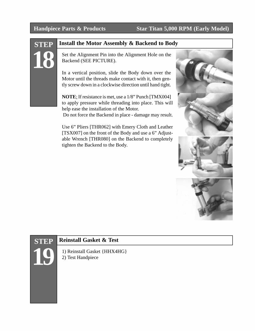
18Install the Motor Assembly & Backend to Body
Set the Alignment Pin into the Alignment Hole on theBackend (SEE PICTURE).
In a vertical position, slide the Body down over theMotor until the threads make contact with it, then gen-tly screw down in a clockwise direction until hand tight.
NOTE: If resistance is met, use a 1/8” Punch [TMX004]to apply pressure while threading into place. This willhelp ease the installation of the Motor. Do not force the Backend in place - damage may result.
Use 6” Pliers [THR062] with Emery Cloth and Leather[TSX007] on the front of the Body and use a 6” Adjust-able Wrench [THR080] on the Backend to completelytighten the Backend to the Body.
Handpiece Parts & Products Star Titan 5,000 RPM (Early Model)
STEP
19Reinstall Gasket & Test
1) Reinstall Gasket {HHX4HG}2) Test Handpiece

NOTE
Special Note
The stainless steel nosecone attachment retaineris removable. It is not always necessary to removeduring repair. If it becomes necessary to remove,DO NOT REMOVE MOTOR ASSEMBLYFROM THE BODY, grip the stainless steelnosecone attachment retainer and Body using 6”Pliers and Leather & Emery Cloth. Position gripover the small diameter of the nosecone attach-ment AND in the center of the Body. USE EX-TREME CAUTION WHEN GRIPING THEBODY. The Body is manufactured from alumi-num and it will deform easily. NEVER GRIPTHE BODY WITHOUT MOTOR HOUSINGINSTALLED.
Handpiece Parts & Products
Handpiece Parts & Products
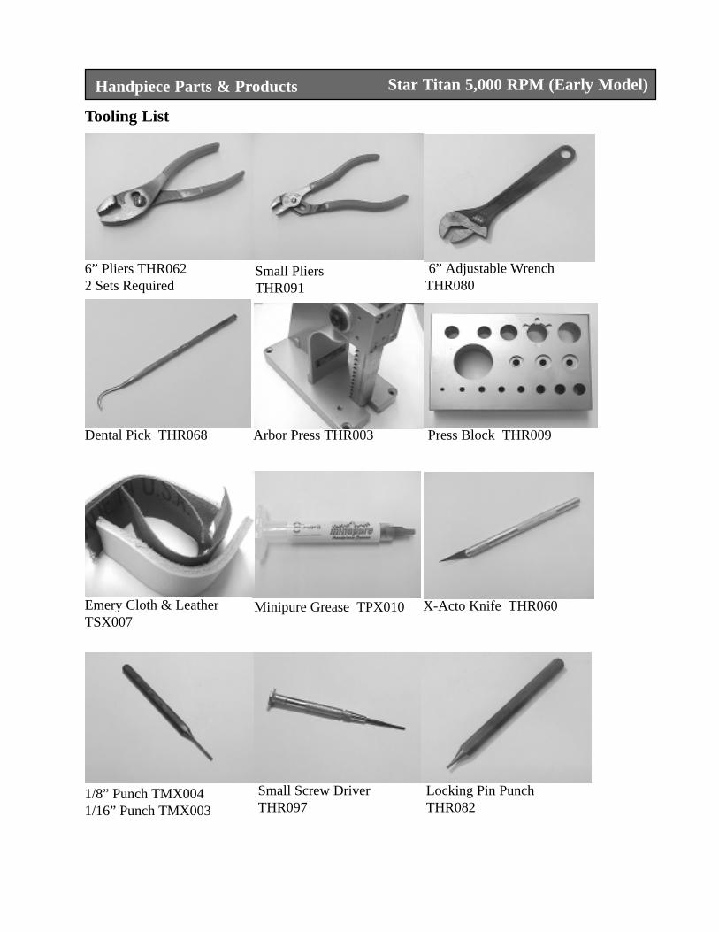
6” Pliers THR0622 Sets Required
Small PliersTHR091
6” Adjustable WrenchTHR080
Dental Pick THR068 Arbor Press THR003 Press Block THR009
X-Acto Knife THR060Minipure Grease TPX010
Tooling List
Emery Cloth & LeatherTSX007
Star Titan 5,000 RPM (Early Model)
1/8” Punch TMX0041/16” Punch TMX003
Locking Pin PunchTHR082
Small Screw DriverTHR097
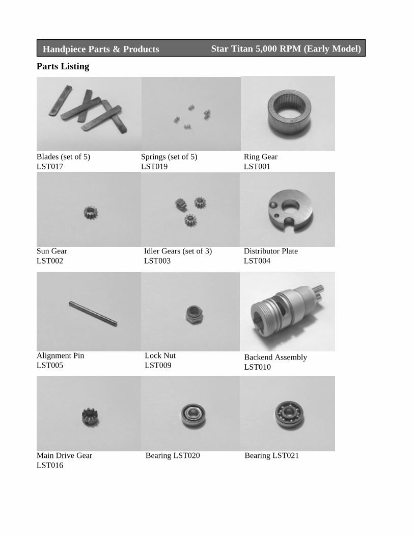
Handpiece Parts & Products
Parts Listing
Star Titan 5,000 RPM (Early Model)
Blades (set of 5)LST017
Springs (set of 5)LST019
Ring GearLST001
Sun GearLST002
Idler Gears (set of 3)LST003
Distributor PlateLST004
Alignment PinLST005
Lock NutLST009
Backend AssemblyLST010
Main Drive GearLST016
Bearing LST020 Bearing LST021
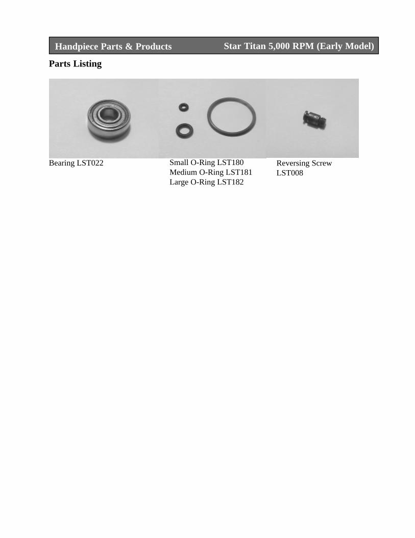
Handpiece Parts & Products
Parts Listing
Star Titan 5,000 RPM (Early Model)
Bearing LST022 Small O-Ring LST180Medium O-Ring LST181Large O-Ring LST182
Reversing ScrewLST008
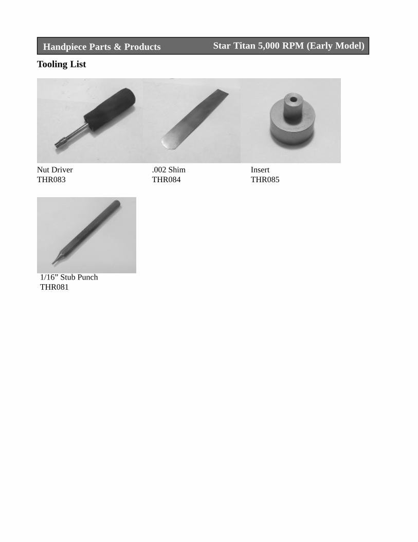
Handpiece Parts & Products
Tooling List
Star Titan 5,000 RPM (Early Model)
Nut DriverTHR083
.002 ShimTHR084
InsertTHR085
1/16” Stub PunchTHR081
Top Related