


Languages
Pages
Legal


ST6 FAMILYPROGRAMMING MANUAL
Rev. 2.0
October 2004
1

PROGRAMMING MANUAL
ST6 FAMILY
Rev. 2.0
INTRODUCTIONThis manual deals with the description of the instruction set and addressing modes of ST6 microcontrollerseries. The manual is divided in two main sections. The first one includes, after a general family descrip-tion, the addressing modes description. The second section includes the detailed description of ST6 in-struction set. Each instruction is described in detail with the differences between each ST6 series.
Table 1. ST6 Series Core Characteristics
ST6 SeriesStack Levels 6Interrupt Vectors 5NMI YESFlags Sets 3Program ROM 2K + 2K∗n
20K MaxData RAM 64 byte*mData ROM 64 byte pages in ROMCarry Flag SUB Instruction
Reset if A > Source
Carry Flag CP Instruction Set if A < Source
October 2004
2/451

Table of Contents
45
INTRODUCTION . . . . . . . . . . . . . . . . . . . . . . . . . . . . . . . . . . . . . . . . . . . . . . . . . . . . . . . 2
1 PROGRAMMING MODEL . . . . . . . . . . . . . . . . . . . . . . . . . . . . . . . . . . . . . . . . . . . . . . 4
2 ADDRESSING MODES . . . . . . . . . . . . . . . . . . . . . . . . . . . . . . . . . . . . . . . . . . . . . . . . 8
3 ST6 INSTRUCTION SET . . . . . . . . . . . . . . . . . . . . . . . . . . . . . . . . . . . . . . . . . . . . . . . 9ADD . . . . . . . . . . . . . . . . . . . . . . . . . . . . . . . . . . . . . . . . . . . . . . . . . . . . . . . . . . . . . . . . . . 14
ADDI . . . . . . . . . . . . . . . . . . . . . . . . . . . . . . . . . . . . . . . . . . . . . . . . . . . . . . . . . . . . . . . . . . 15
AND . . . . . . . . . . . . . . . . . . . . . . . . . . . . . . . . . . . . . . . . . . . . . . . . . . . . . . . . . . . . . . . . . . 16
ANDI . . . . . . . . . . . . . . . . . . . . . . . . . . . . . . . . . . . . . . . . . . . . . . . . . . . . . . . . . . . . . . . . . . 17
CALL . . . . . . . . . . . . . . . . . . . . . . . . . . . . . . . . . . . . . . . . . . . . . . . . . . . . . . . . . . . . . . . . . 18
CLR . . . . . . . . . . . . . . . . . . . . . . . . . . . . . . . . . . . . . . . . . . . . . . . . . . . . . . . . . . . . . . . . . . 19
COM . . . . . . . . . . . . . . . . . . . . . . . . . . . . . . . . . . . . . . . . . . . . . . . . . . . . . . . . . . . . . . . . . . 20
CP . . . . . . . . . . . . . . . . . . . . . . . . . . . . . . . . . . . . . . . . . . . . . . . . . . . . . . . . . . . . . . . . . . . 21
CPI . . . . . . . . . . . . . . . . . . . . . . . . . . . . . . . . . . . . . . . . . . . . . . . . . . . . . . . . . . . . . . . . . . . 22
DEC . . . . . . . . . . . . . . . . . . . . . . . . . . . . . . . . . . . . . . . . . . . . . . . . . . . . . . . . . . . . . . . . . . 23
INC . . . . . . . . . . . . . . . . . . . . . . . . . . . . . . . . . . . . . . . . . . . . . . . . . . . . . . . . . . . . . . . . . . . 24
JP . . . . . . . . . . . . . . . . . . . . . . . . . . . . . . . . . . . . . . . . . . . . . . . . . . . . . . . . . . . . . . . . . . . 25
JRC . . . . . . . . . . . . . . . . . . . . . . . . . . . . . . . . . . . . . . . . . . . . . . . . . . . . . . . . . . . . . . . . . . 26
JRNC . . . . . . . . . . . . . . . . . . . . . . . . . . . . . . . . . . . . . . . . . . . . . . . . . . . . . . . . . . . . . . . . . 27
JRNZ . . . . . . . . . . . . . . . . . . . . . . . . . . . . . . . . . . . . . . . . . . . . . . . . . . . . . . . . . . . . . . . . . 28
JRR . . . . . . . . . . . . . . . . . . . . . . . . . . . . . . . . . . . . . . . . . . . . . . . . . . . . . . . . . . . . . . . . . . 29
JRS . . . . . . . . . . . . . . . . . . . . . . . . . . . . . . . . . . . . . . . . . . . . . . . . . . . . . . . . . . . . . . . . . . 30
JRZ . . . . . . . . . . . . . . . . . . . . . . . . . . . . . . . . . . . . . . . . . . . . . . . . . . . . . . . . . . . . . . . . . . . 31
LD . . . . . . . . . . . . . . . . . . . . . . . . . . . . . . . . . . . . . . . . . . . . . . . . . . . . . . . . . . . . . . . . . . . 32
LDI . . . . . . . . . . . . . . . . . . . . . . . . . . . . . . . . . . . . . . . . . . . . . . . . . . . . . . . . . . . . . . . . . . . 33
NOP . . . . . . . . . . . . . . . . . . . . . . . . . . . . . . . . . . . . . . . . . . . . . . . . . . . . . . . . . . . . . . . . . . 34
RES . . . . . . . . . . . . . . . . . . . . . . . . . . . . . . . . . . . . . . . . . . . . . . . . . . . . . . . . . . . . . . . . . . 35
RET . . . . . . . . . . . . . . . . . . . . . . . . . . . . . . . . . . . . . . . . . . . . . . . . . . . . . . . . . . . . . . . . . . 36
RETI . . . . . . . . . . . . . . . . . . . . . . . . . . . . . . . . . . . . . . . . . . . . . . . . . . . . . . . . . . . . . . . . . . 37
RLC . . . . . . . . . . . . . . . . . . . . . . . . . . . . . . . . . . . . . . . . . . . . . . . . . . . . . . . . . . . . . . . . . . 38
SET . . . . . . . . . . . . . . . . . . . . . . . . . . . . . . . . . . . . . . . . . . . . . . . . . . . . . . . . . . . . . . . . . . 39
SLA . . . . . . . . . . . . . . . . . . . . . . . . . . . . . . . . . . . . . . . . . . . . . . . . . . . . . . . . . . . . . . . . . . 40
STOP . . . . . . . . . . . . . . . . . . . . . . . . . . . . . . . . . . . . . . . . . . . . . . . . . . . . . . . . . . . . . . . . . 41
SUB . . . . . . . . . . . . . . . . . . . . . . . . . . . . . . . . . . . . . . . . . . . . . . . . . . . . . . . . . . . . . . . . . . 42
SUBI . . . . . . . . . . . . . . . . . . . . . . . . . . . . . . . . . . . . . . . . . . . . . . . . . . . . . . . . . . . . . . . . . . 43
WAIT . . . . . . . . . . . . . . . . . . . . . . . . . . . . . . . . . . . . . . . . . . . . . . . . . . . . . . . . . . . . . . . . . 44
3/45

PROGRAMMING MODEL
1 PROGRAMMING MODEL
It is useful at this stage to outline the programming model of the ST6 series, by which we mean the avail-able memory spaces, their relation to one another, the interrupt philosophy and so on.
Memory Spaces. The ST6 devices have three different memory spaces: data, program and stack. All ad-dressing modes are memory space specific so there is no need for the user to specify which space is be-ing used as in more complex systems. The stack space, which is used automatically with subroutine andinterrupt management for program counter storage, is not accessible to the user.
Figure 1. ST6 Family Programming Model
V REGISTER
W REGISTER
PROGRAM COUNTER
SIX LEVELSSTACK REGISTER
C
C
C
Z
Z
Z
NORMAL FLAGS
INTERRUPT FLAGS
NMI FLAGS
INDEXREGISTER
VA000423
b7
b7
b7
b7
b7
b0
b0
b0
b0
b0
b0b11
ACCUMULATOR
Y REG. POINTER
X REG. POINTERSHORTDIRECT
ADDRESSINGMODE
4/45
1

PROGRAMMING MODEL
PROGRAMMING MODEL (Cont’d)
Figure 2. ST6 Data Space Example
b7 b0
NOT IMPLEMENTED000h03Fh
DATA ROM/EPROM WINDOW 64 BYTE040h07Fh
X REGISTER 080h
Y REGISTER 081h
V REGISTER 082h
W REGISTER 083h
DATA RAM 60 BYTES084h
0BFh
PORT A DATA REGISTER - DRA 0C0h
PORT B DATA REGISTER - DRB 0C1h
PORT C DATA REGISTER - DRC 0C2h
RESERVED 0C3h
PORT A DATA DIRECTION REGISTER - DDRA 0C4h
PORT B DATA DIRECTION REGISTER - DDRB 0C5h
PORT C DATA DIRECTION REGISTER - DDRC 0C6h
RESERVED 0C7h
INTERRUPT OPTION REGISTER - IOR 0C8h
DATA ROM WINDOW REGISTER - DRWR 0C9h
RESERVED0CAh
0CBh
PORT A OPTION REGISTER - ORA 0CCh
PORT B OPTION REGISTER -ORB 0CDh
PORT C OPTION REGISTER - ORC 0CEh
RESERVED 0CFh
A/D DATA REGISTER - ADR 0D0h
A/D CONTROL REGISTER - ADCR 0D1h
TIMER PSC REGISTER - PSCR 0D2h
TIMER COUNTER REGISTER - TCR 0D3h
TIMER STATUS CONTROL REGISTER - TSCR 0D4h
RESERVED
0D5h
0D6h
0D7h
WATCHDOG REGISTER - WDGR 0D8h
RESERVED
0D9h
0FEh
ACCUMULATOR OFFh
5/45

PROGRAMMING MODEL
Figure 3. ST6 Program Memory Example
Data Memory Space. The following registers in the data space have fixed addresses which are hardwareselected so as to decrease access times and reduce addressing requirements and hence program length.The Accumulator is an 8-bit register in location 0FFh. The X, Y, V & W registers have the addresses 80h-83h respectively. These are used for short direct addressing, reducing byte requirements in the programwhile the first two, X & Y, can also be used as index registers in the indirect addressing mode. These reg-isters are part of the data RAM space. In the ST6 for data space ROM a 6-bit (64 bytes addressing) win-dow multiplexing in program ROM is available through a dedicated data ROM banking register.
b7 b0
NOT IMPLEMENTED0000h
07FFh
RESERVED0800h
087Fh
USER PROGRAM ROM 1828 BYTES
0880h
0F9Fh
RESERVED0FA0h0FEFh
INTERRUPT VECTOR #4A/D INTERRUPT
0FF0h0FF1h
INTERRUPT VECTOR #3TIMER INTERRUPT
0FF2h0FF3h
INTERRUPT VECTOR #2PORT B & C INTERRUPT
0FF4h0FF5h
INTERRUPT VECTOR #1PORT A INTERRUPT
0FF6h0FF7h
RESERVED
0FF8h
0FFBh
INTERRUPT VECTOR #0NMI INTERRUPT
0FFCh0FFDh
USER RESET VECTOR0FFEh0FFFh
On EPROM versions there are no re-served areas. These reserved bytes are present on ROM/OTP versions.
6/45

PROGRAMMING MODEL
PROGRAMMING MODEL (Cont’d)
For data RAM and I/O expansion the lowest 64 bytes of data space (00h-03Fh) are paged through a dataRAM banking register.
Self-check Interrupt Vector FF8h & FF9h:jp (self-check interrupt routine)
A jump instruction to the reset and interrupt routines must be written into these locations.
ST6 Program Memory Space. The ST6 devices can directly address up to 4K bytes (program counter is12 bits wide). A greater ROM size is obtained by paging the lower 2K of the program ROM through a ded-icated banking register located in the data space. The higher 2K of the program ROM can be seen as stat-ic and contains the reset, NMI and interrupt vectors at the following fixed locations:
Program Counter & Stack Area. The program counter is a 12-bit counter register since it has to cover adirect addressing of 4K byte program memory space. When an interrupt or a subroutine occurs the currentPC value is forward "pushed" into a deep LIFO stacking area. On the return from the routine the top (lastin) PC value is "popped" out and becomes the current PC value. The ST60/61 series offer a 4-word deepstack for program counter storage during interrupt and sub-routines calls. In the ST6 series the stack is 6-word deep.
Status Flags. Three pairs of status flags, each pair consisting of a Zero flag and a Carry flag, are availa-ble. In the ST6 an additional third set is available. One pair monitors the normal status while the secondmonitors the state during interrupts; the third flags set monitors the status during Non Maskable interruptservicing. The switching from one set to another is automatic as the interrupt requests (or NMI request forST6 only) are acknowledged and when the program returns after an interrupt service routine. After reset,the NMI set is active, until the first RETI instruction is executed.
ST6 Interrupt Description. The ST6 devices have 5 user interrupt vectors (plus one vector for testingpurposes). Interrupt vector #0 is connected to the not maskable interrupt input of the core. Interrupts from#1 to #4 can be connected to different on-chip and external sources (see individual datasheets for detailedinformation). All interrupts can be globally disabled through the interrupt option register. After the resetST6 devices are in NMI mode, so no other interrupts can be accepted and the NMI flags set is in use, untilthe RETI instruction is performed. If an interrupt is detected, a special cycle is executed. During this cycle,the program counter is loaded with the related interrupt vector address. NMI can interrupt other interruptroutines at any time while normal interrupt can't interrupt each other. If more than one interrupt is awaitingservice, they will be accepted according to their priority. Interrupt #1 has the highest priority while interrupt#4 the lowest. This priority relationship is fixed.
Figure 4. ST6 Stack Area
Reset Vector FFEh & FFFh:jp (reset routine)
NMI Interrupt Vector FFCh & FFDh:jp (NMI routine)
Non user Vector FFAh & FFBh
Non user Vector FF8h & FF9h
Interrupt #1 Vector FF6h & FF7h jp (Int 1 routine)
Interrupt #2 Vector FF4h & FF5h jp (Int 2 routine)
Interrupt #3 Vector FF2h & FF3h jp (Int 3 routine)
Interrupt #4 Vector FF0h & FF1h jp (Int 4 routine)
WHEN CALLOR
INTERRUPTREQUESTOCCURS
STACK LEVEL 1
STACK LEVEL 2
STACK LEVEL 3
STACK LEVEL 4
STACK LEVEL 5
STACK LEVEL 6
PROGRAMCOUNTER
WHENRET OR RETI
OCCURS
VA000424
7/45

ADDRESSING MODES
2 ADDRESSING MODES
The ST6 core offers nine addressing modes, which are described in the following paragraphs. Three dif-ferent address spaces are available: Program space, Data space, and Stack space. Program space con-tains the instructions which are to be executed, plus the data for immediate mode instructions. Data spacecontains the Accumulator, the X,Y,V and W registers, peripheral and Input/Output registers, the RAM lo-cations and Data ROM locations (for storage of tables and constants). Stack space contains six 12-bitRAM cells used to stack the return addresses for subroutines and interrupts.
Immediate. In the immediate addressing mode, the operand of the instruction follows the opcode loca-tion. As the operand is a ROM byte, the immediate addressing mode is used to access constants whichdo not change during program execution (e.g., a constant used to initialize a loop counter).
Direct. In the direct addressing mode, the address of the byte which is processed by the instruction isstored in the location which follows the opcode. Direct addressing allows the user to directly address the256 bytes in Data Space memory with a single two-byte instruction.
Short Direct. The core can address the four RAM registers X,Y,V,W (locations 80h, 81h, 82h, 83h) in theshort-direct addressing mode. In this case, the instruction is only one byte and the selection of the locationto be processed is contained in the opcode. Short direct addressing is a subset of the direct addressingmode. (Note that 80h and 81h are also indirect registers).
Extended. In the extended addressing mode, the 12-bit address needed to define the instruction is ob-tained by concatenating the four less significant bits of the opcode with the byte following the opcode. Theinstructions (JP, CALL) which use the extended addressing mode are able to branch to any address of the4K bytes Program space.
An extended addressing mode instruction is 2-bytes long.
Program Counter Relative. The relative addressing mode is only used in conditional branch instructions.The instruction is used to perform a test and, if the condition is true, a branch with a span of -15 to +16 lo-cations around the address of the relative instruction. If the condition is not true, the instruction which fol-lows the relative instruction is executed. The relative addressing mode instruction is one-byte long. Theopcode is obtained by adding the three most significant bits which characterize the kind of the test, one bitwhich determines whether the branch is a forward (when it is 0) or backward (when it is 1) branch and thefour less significant bits which give the span of the branch (0h to Fh) which must be added or subtractedto the address of the relative instruction to obtain the address of the branch.
Bit Direct. In the bit direct addressing mode, the bit to be set or cleared is part of the opcode, and the bytefollowing the opcode points to the address of the byte in which the specified bit must be set or cleared.Thus, any bit in the 256 locations of Data space memory can be set or cleared.
Bit Test & Branch. The bit test and branch addressing mode is a combination of direct addressing andrelative addressing. The bit test and branch instruction is three-byte long. The bit identification and thetested condition are included in the opcode byte. The address of the byte to be tested follows immediatelythe opcode in the Program space. The third byte is the jump displacement, which is in the range of -127to +128. This displacement can be determined using a label, which is converted by the assembler.
Indirect. In the indirect addressing mode, the byte processed by the register-indirect instruction is at theaddress pointed by the content of one of the indirect registers, X or Y (80h,81h). The indirect register is se-lected by the bit 4 of the opcode. A register indirect instruction is one byte long.
Inherent. In the inherent addressing mode, all the information necessary to execute the instruction is con-tained in the opcode. These instructions are one byte long.
8/45

ST6 INSTRUCTION SET
3 ST6 INSTRUCTION SET
The ST6 core offers a set of 40 basic instructions which, when combined with nine addressing modes,yield 244 usable opcodes. They can be divided into six different types: load/store, arithmetic/logic, condi-tional branch, control instructions, jump/call, and bit manipulation. The following paragraphs describe thedifferent types.
All the instructions belonging to a given type are presented in individual tables.
Load & Store. These instructions use one, two or three bytes in relation with the addressing mode. Oneoperand is the Accumulator for LOAD and the other operand is obtained from data memory using one ofthe addressing modes.
For Load Immediate one operand can be any of the 256 data space bytes while the other is always imme-diate data. Table 2. Load & Store Instructions
Notes:X,Y. Indirect Register Pointers, V & W Short Direct Registers# . Immediate data (stored in ROM memory)rr. Data space register∆. Affected* . Not Affected
Instruction Addressing Mode Bytes CyclesFlags
Z CLD A, X Short Direct 1 4 ∆ *LD A, Y Short Direct 1 4 ∆ *LD A, V Short Direct 1 4 ∆ *LD A, W Short Direct 1 4 ∆ *LD X, A Short Direct 1 4 ∆ *LD Y, A Short Direct 1 4 ∆ *LD V, A Short Direct 1 4 ∆ *LD W, A Short Direct 1 4 ∆ *LD A, rr Direct 2 4 ∆ *LD rr, A Direct 2 4 ∆ *LD A, (X) Indirect 1 4 ∆ *LD A, (Y) Indirect 1 4 ∆ *LD (X), A Indirect 1 4 ∆ *LD (Y), A Indirect 1 4 ∆ *LDI A, #N Immediate 2 4 ∆ *LDI rr, #N Immediate 3 4 * *
9/45

ST6 INSTRUCTION SET
ST6 INSTRUCTION SET (Cont’d)
Arithmetic and Logic. These instructions are used to perform the arithmetic calculations and logic oper-ations. In AND, ADD, CP, SUB instructions one operand is always the accumulator while the other can beeither a data space memory content or an immediate value in relation with the addressing mode. In CLR,DEC, INC instructions the operand can be any of the 256 data space addresses. In COM, RLC, SLA theoperand is always the accumulator.Table 3. Arithmetic & Logic Instructions
Notes:X,Y. Indirect Register Pointers, V & W Short Direct Registers ∆. Affected# . Immediate data (stored in ROM memory) * . Not Affectedrr. Data space register
Instruction Addressing Mode Bytes CyclesFlags
Z CADD A, (X) Indirect 1 4 ∆ ∆ADD A, (Y) Indirect 1 4 ∆ ∆ADD A, rr Direct 2 4 ∆ ∆ADDI A, #N Immediate 2 4 ∆ ∆AND A, (X) Indirect 1 4 ∆ ∆AND A, (Y) Indirect 1 4 ∆ ∆AND A, rr Direct 2 4 ∆ ∆ANDI A, #N Immediate 2 4 ∆ ∆CLR A Short Direct 2 4 ∆ ∆CLR r Direct 3 4 * *COM A Inherent 1 4 ∆ ∆CP A, (X) Indirect 1 4 ∆ ∆CP A, (Y) Indirect 1 4 ∆ ∆CP A, rr Direct 2 4 ∆ ∆CPI A, #N Immediate 2 4 ∆ ∆DEC X Short Direct 1 4 ∆ *DEC Y Short Direct 1 4 ∆ *DEC V Short Direct 1 4 ∆ *DEC W Short Direct 1 4 ∆ *DEC A Direct 2 4 ∆ *DEC rr Direct 2 4 ∆ *DEC (X) Indirect 1 4 ∆ *DEC (Y) Indirect 1 4 ∆ *INC X Short Direct 1 4 ∆ *INC Y Short Direct 1 4 ∆ *INC V Short Direct 1 4 ∆ *INC W Short Direct 1 4 ∆ *INC A Direct 2 4 ∆ *INC rr Direct 2 4 ∆ *INC (X) Indirect 1 4 ∆ *INC (Y) Indirect 1 4 ∆ *RLC A Inherent 1 4 ∆ ∆SLA A Inherent 2 4 ∆ ∆SUB A, (X) Indirect 1 4 ∆ ∆SUB A, (Y) Indirect 1 4 ∆ ∆SUB A, rr Direct 2 4 ∆ ∆SUBI A, #N Immediate 2 4 ∆ ∆
10/45

ST6 INSTRUCTION SET
ST6 INSTRUCTION SET (Cont’d)
Conditional Branch. The branch instructions achieve a branch in the program when the selected condi-tion is met.
Bit Manipulation Instructions. These instructions can handle any bit in data space memory. One groupeither sets or clears. The other group (see Conditional Branch) performs the bit test branch operations.
Control Instructions. The control instructions control the MCU operations during program execution.
Jump and Call. These two instructions are used to perform long (12-bit) jumps or subroutine calls insidethe whole program space. Table 4. Conditional Branch Instructions
Notes:b. 3-bit address rr. Data space registere. 5-bit signed displacement in the range -15 to +16<F128M> ∆ . Affected. The tested bit is shifted into carry.ee. 8-bit signed displacement in the range -126 to +129 * . Not Affected
Table 5. Bit Manipulation Instructions
Notes: b. 3-bit address * . Not Affectedrr. Data space register
Table 6. Control Instructions
Notes:1. This instruction is deactivated and a WAIT is automatically executed instead of a STOP if the watchdog function is selected.∆ . Affected*. Not Affected
Table 7. Jump & Call Instructions
Notes: abc. 12-bit address* . Not Affected
Instruction Branch If Bytes CyclesFlags
Z CJRC e C = 1 1 2 * *JRNC e C = 0 1 2 * *JRZ e Z = 1 1 2 * *JRNZ e Z = 0 1 2 * *JRR b, rr, ee Bit = 0 3 5 * ∆JRS b, rr, ee Bit = 1 3 5 * ∆
Instruction Addressing Mode Bytes CyclesFlags
Z CSET b,rr Bit Direct 2 4 * *RES b,rr Bit Direct 2 4 * *
Instruction Addressing Mode Bytes CyclesFlags
Z CNOP Inherent 1 2 * *RET Inherent 1 2 * *RETI Inherent 1 2 ∆ ∆STOP (1) Inherent 1 2 * *WAIT Inherent 1 2 * *
InstructionAddressing Mode Bytes Cycles
Flags
Z C
CALL abc Extended 2 4 * *JP abc Extended 2 4 * *
11/45

ST6 INSTRUCTION SET
Opcode Map Summary. The following table contains an opcode map for the instructions used by the ST6LOW
00000
10001
20010
30011
40100
50101
60110
70111
LOW
HI HI
00000
2 JRNZ 4 CALL 2 JRNC 5 JRR 2 JRZ 2 JRC 4 LD0
0000e abc e b0,rr,ee e # e a,(x)1 pcr 2 ext 1 pcr 3 bt 1 pcr 1 prc 1 ind
10001
2 JRNZ 4 CALL 2 JRNC 5 JRS 2 JRZ 4 INC 2 JRC 4 LDI1
0001e abc e b0,rr,ee e x e a,nn1 pcr 2 ext 1 pcr 3 bt 1 pcr 1 sd 1 prc 2 imm
20010
2 JRNZ 4 CALL 2 JRNC 5 JRR 2 JRZ 2 JRC 4 CP2
0010e abc e b4,rr,ee e # e a,(x)1 pcr 2 ext 1 pcr 3 bt 1 pcr 1 prc 1 ind
30011
2 JRNZ 4 CALL 2 JRNC 5 JRS 2 JRZ 4 LD 2 JRC 4 CPI3
0011e abc e b4,rr,ee e a,x e a,nn1 pcr 2 ext 1 pcr 3 bt 1 pcr 1 sd 1 prc 2 imm
40100
2 JRNZ 4 CALL 2 JRNC 5 JRR 2 JRZ 2 JRC 4 ADD4
0100e abc e b2,rr,ee e # e a,(x)1 pcr 2 ext 1 pcr 3 bt 1 pcr 1 prc 1 ind
50101
2 JRNZ 4 CALL 2 JRNC 5 JRS 2 JRZ 4 INC 2 JRC 4 ADDI5
0101e abc e b2,rr,ee e y e a,nn1 pcr 2 ext 1 pcr 3 bt 1 pcr 1 sd 1 prc 2 imm
60110
2 JRNZ 4 CALL 2 JRNC 5 JRR 2 JRZ 2 JRC 4 INC6
0110e abc e b6,rr,ee e # e (x)1 pcr 2 ext 1 pcr 3 bt 1 pcr 1 prc 1 ind
70111
2 JRNZ 4 CALL 2 JRNC 5 JRS 2 JRZ 4 LD 2 JRC7
0111e abc e b6,rr,ee e a,y e #1 pcr 2 ext 1 pcr 3 bt 1 pcr 1 sd 1 prc
81000
2 JRNZ 4 CALL 2 JRNC 5 JRR 2 JRZ 2 JRC 4 LD8
1000e abc e b1,rr,ee e # e (x),a1 pcr 2 ext 1 pcr 3 bt 1 pcr 1 prc 1 ind
91001
2 RNZ 4 CALL 2 JRNC 5 JRS 2 JRZ 4 INC 2 JRC9
1001e abc e b1,rr,ee e v e #1 pcr 2 ext 1 pcr 3 bt 1 pcr 1 sd 1 prc
A1010
2 JRNZ 4 CALL 2 JRNC 5 JRR 2 JRZ 2 JRC 4 ANDA
1010e abc e b5,rr,ee e # e a,(x)1 pcr 2 ext 1 pcr 3 bt 1 pcr 1 prc 1 ind
B1011
2 JRNZ 4 CALL 2 JRNC 5 JRS 2 JRZ 4 LD 2 JRC 4 ANDIB
1011e abc e b5,rr,ee e a,v e a,nn1 pcr 2 ext 1 pcr 3 bt 1 pcr 1 sd 1 prc 2 imm
C1100
2 JRNZ 4 CALL 2 JRNC 5 JRR 2 JRZ 2 JRC 4 SUBC
1100e abc e b3,rr,ee e # e a,(x)1 pcr 2 ext 1 pcr 3 bt 1 pcr 1 prc 1 ind
D1101
2 JRNZ 4 CALL 2 JRNC 5 JRS 2 JRZ 4 INC 2 JRC 4 SUBID
1101e abc e b3,rr,ee e w e a,nn1 pcr 2 ext 1 pcr 3 bt 1 pcr 1 sd 1 prc 2 imm
E1110
2 JRNZ 4 CALL 2 JRNC 5 JRR 2 JRZ 2 JRC 4 DECE
1110e abc e b7,rr,ee e # e (x)1 pcr 2 ext 1 pcr 3 bt 1 pcr 1 prc 1 ind
F1111
2 JRNZ 4 CALL 2 JRNC 5 JRS 2 JRZ 4 LD 2 JRCF
1111e abc e b7,rr,ee e a,w e #1 pcr 2 ext 1 pcr 3 bt 1 pcr 1 sd 1 prc
Abbreviations for Addressing Modes: Legend: dir Direct # Indicates Illegal Instructions sd Short Direct e 5-Bit Displacement imm Immediate b 3-Bit Address inh Inherent rr 1byte dataspace address ext Extended nn 1 byte immediate data b.d Bit Direct abc 12-bit address bt Bit Test ee 8-bit Displacement pcr Program Counter Relativeind Indirect
2 JRCe
1 prc
Mnemonic
Addressing Mode
Bytes
Cycle
Operand
12/45

ST6 INSTRUCTION SET
Opcode Map Summary (Continued)LOW
81000
91001
A1010
B1011
C1100
D1101
E1110
F1111
LOW
HI HI
00000
2 JRNZ 4 JP 2 JRNC 4 RES 2 JRZ 4 LDI 2 JRC 4 LD0
0000e abc e b0,rr e rr,nn e a,(y)1 pcr 2 ext 1 pcr 2 b.d 1 pcr 3 imm 1 prc 1 ind
10001
2 JRNZ 4 JP 2 JRNC 4 SET 2 JRZ 4 DEC 2 JRC 4 LD1
0001e abc e b0,rr e x e a,rr1 pcr 2 ext 1 pcr 2 b.d 1 pcr 1 sd 1 prc 2 dir
20010
2 JRNZ 4 JP 2 JRNC 4 RES 2 JRZ 4 COM 2 JRC 4 CP2
0010e abc e b4,rr e a e a,(y)1 pcr 2 ext 1 pcr 2 b.d 1 pcr 1 prc 1 ind
30011
2 JRNZ 4 JP 2 JRNC 4 SET 2 JRZ 4 LD 2 JRC 4 CP3
0011e abc e b4,rr e x,a e a,rr1 pcr 2 ext 1 pcr 2 b.d 1 pcr 1 sd 1 prc 2 dir
40100
2 JRNZ 4 JP 2 JRNC 4 RES 2 JRZ 2 RETI 2 JRC 4 ADD4
0100e abc e b2,rr e e a,(y)1 pcr 2 ext 1 pcr 2 b.d 1 pcr 1 inh 1 prc 1 ind
50101
2 JRNZ 4 JP 2 JRNC 4 SET 2 JRZ 4 DEC 2 JRC 4 ADD5
0101e abc e b2,rr e y e a,rr1 pcr 2 ext 1 pcr 2 b.d 1 pcr 1 sd 1 prc 2 dir
60110
2 JRNZ 4 JP 2 JRNC 4 RES 2 JRZ 2 STOP 2 JRC 4 INC6
0110e abc e b6,rr e e (y)1 pcr 2 ext 1 pcr 2 b.d 1 pcr 1 inh 1 prc 1 ind
70111
2 JRNZ 4 JP 2 JRNC 4 SET 2 JRZ 4 LD 2 JRC 4 INC7
0111e abc e b6,rr e y,a e rr1 pcr 2 ext 1 pcr 2 b.d 1 pcr 1 sd 1 prc 2 dir
81000
2 JRNZ 4 JP 2 JRNC 4 RES 2 JRZ 2 JRC 4 LD8
1000e abc e b1,rr e # e (y),a1 pcr 2 ext 1 pcr 2 b.d 1 pcr 1 prc 1 ind
91001
2 RNZ 4 JP 2 JRNC 4 SET 2 JRZ 4 DEC 2 JRC 4 LD9
1001e abc e b1,rr e v e rr,a1 pcr 2 ext 1 pcr 2 b.d 1 pcr 1 sd 1 prc 2 dir
A1010
2 JRNZ 4 JP 2 JRNC 4 RES 2 JRZ 4 RCL 2 JRC 4 ANDA
1010e abc e b5,rr e a e a,(y)1 pcr 2 ext 1 pcr 2 b.d 1 pcr 1 inh 1 prc 1 ind
B1011
2 JRNZ 4 JP 2 JRNC 4 SET 2 JRZ 4 LD 2 JRC 4 ANDB
1011e abc e b5,rr e v,a e a,rr1 pcr 2 ext 1 pcr 2 b.d 1 pcr 1 sd 1 prc 2 dir
C1100
2 JRNZ 4 JP 2 JRNC 4 RES 2 JRZ 2 RET 2 JRC 4 SUBC
1100e abc e b3,rr e e a,(y)1 pcr 2 ext 1 pcr 2 b.d 1 pcr 1 inh 1 prc 1 ind
D1101
2 JRNZ 4 JP 2 JRNC 4 SET 2 JRZ 4 DEC 2 JRC 4 SUBD
1101e abc e b3,rr e w e a,rr1 pcr 2 ext 1 pcr 2 b.d 1 pcr 1 sd 1 prc 2 dir
E1110
2 JRNZ 4 JP 2 JRNC 4 RES 2 JRZ 2 WAIT 2 JRC 4 DECE
1110e abc e b7,rr e e (y)1 pcr 2 ext 1 pcr 2 b.d 1 pcr 1 inh 1 prc 1 ind
F1111
2 JRNZ 4 JP 2 JRNC 4 SET 2 JRZ 4 LD 2 JRC 4 DECF
1111e abc e b7,rr e w,a e rr1 pcr 2 ext 1 pcr 2 b.d 1 pcr 1 sd 1 prc 2 dir
Abbreviations for Addressing Modes: Legend: dir Direct # Indicates Illegal Instructions sd Short Direct e 5-Bit Displacement imm Immediate b 3-Bit Address inh Inherent rr 1byte dataspace address ext Extended nn 1 byte immediate data b.d Bit Direct abc 12-bit address bt Bit Test ee 8-bit Displacement pcr Program Counter Relativeind Indirect
2 JRCe
1 prc
Mnemonic
Addressing Mode
Bytes
Cycle
Operand
13/45

ST6 INSTRUCTION SET
ADD Addition ADDMnemonic: ADD
Function: Addition
Description: The contents of the source byte is added to the accumulator leaving the result in the accumulator. The source register remains unaltered.
Operation: dst ! dst + srcThe destination must be the accumulator.
Notes:rr. 1 Byte dataspace address.∆: Z is set if the result is zero. Cleared otherwise.
C is cleared before the operation and than set if there is an overflow from the 8-bit result.
Example: If data space register 22h contains the value 33h and the accumulator holds thevalue 20h then the instruction,
ADD A,22h
will cause the accumulator to hold 53h (i.e. 33+20).
Addressing Modes: Source: Direct, Indirect
Destination: Accumulator
Instruction FormatOpcode (Hex) Bytes Cycles
FlagsADD dst,src Z C
ADD A,A 5F FF 2 4 ∆ ∆ADD A,X 5F 80 2 4 ∆ ∆ADD A,Y 5F 81 2 4 ∆ ∆ADD A,V 5F 82 2 4 ∆ ∆ADD A,W 5F 83 2 4 ∆ ∆ADD A,(X) 47 1 4 ∆ ∆ADD A,(Y) 4F 1 4 ∆ ∆ADD A,rr 5F rr 2 4 ∆ ∆
14/45
ST6 INSTRUCTION SET
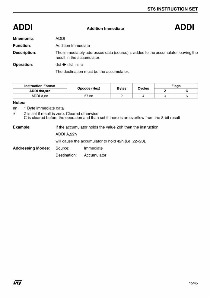
ADDI Addition Immediate ADDIMnemonic: ADDI
Function: Addition Immediate
Description: The immediately addressed data (source) is added to the accumulator leaving theresult in the accumulator.
Operation: dst ! dst + src
The destination must be the accumulator.
Notes:nn. 1 Byte immediate data∆: Z is set if result is zero. Cleared otherwise
C is cleared before the operation and than set if there is an overflow from the 8-bit result
Example: If the accumulator holds the value 20h then the instruction,
ADDI A,22h
will cause the accumulator to hold 42h (i.e. 22+20).
Addressing Modes: Source: Immediate
Destination: Accumulator
Instruction FormatOpcode (Hex) Bytes Cycles
FlagsADDI dst,src Z C
ADDI A,nn 57 nn 2 4 ∆ ∆
15/45

ST6 INSTRUCTION SET
AND Logical AND ANDMnemonic: AND
Function: Logical AND
Description: This instruction logically ANDs the source register and the accumulator. Theresult is left in the destination register and the source is unaltered.
Operation: dst ! src AND dst
The destination must be the accumulator.
Notes:rr. 1 Byte dataspace address*. C is unaffected∆. Z is set if the result is zero. Cleared otherwise.
Example: If data space register 54h contains the binary value 11110000 and theaccumulator contains the binary value 11001100 then the instruction,
AND A,54h
will cause the accumulator to be altered to 11000000.
Addressing Modes: Source: Direct, Indirect.
Destination: Accumulator
Instruction FormatOpcode (Hex) Bytes Cycles
FlagsAND dst,src Z C
AND A,A BF FF 2 4 ∆ *AND A,X BF 80 2 4 ∆ *AND A,Y BF 81 2 4 ∆ *AND A,V BF 82 2 4 ∆ *AND A,W BF 83 2 4 ∆ *AND A,(X) A7 1 4 ∆ *AND A,(Y) AF 1 4 ∆ *AND A,rr BF rr 2 4 ∆ *
16/45

ST6 INSTRUCTION SET
ANDI Logical AND Immediate ANDIMnemonic: ANDI
Function: Logical AND Immediate
Description: This instruction logically ANDs the immediate data byte and the accumulator.The result is left in the accumulator.
Operation: dst ! src AND dst
The source is immediate data and the destination must be the accumulator.
Notes:nn. 1 Byte immediate data*. C is unaffected∆. Z is set if the result is zero. Cleared otherwise.
Example: If the accumulator contains the binary value 00001111 then the instruction,
ANDI A,33h
will cause the accumulator to hold the value 00000011.
Addressing Modes: Source: Immediate
Destination: Accumulator
Instruction FormatOpcode (Hex) Bytes Cycles
FlagsANDI dst,src Z C
ANDI A,nn B7 nn 2 4 ∆ *
17/45

ST6 INSTRUCTION SET
CALL Call Subroutine CALLMnemonic: CALL
Function: Call Subroutine
Description: The CALL instruction is used to call a subroutine. It "pushes" the current contentsof the program counter (PC) onto the top of the stack. The specified destinationaddress is then loaded into the PC and points to the first instruction of aprocedure. At the end of the procedure a RETurn instruction can be used to returnto the original program flow. RET pops the top of the stack back into the PC.Because the ST6 stack is 4 levels deep (ST60) and 6 levels deep (ST62,ST63),a maximum of four/six calls or interrupts may be nested. If more calls are nested, the latest stacked PC values will be lost. In this case returns will return to the PC values stacked first.
Operation: PC ! dst; Top of stack ! PC
Notes:abc. the three half bytes of a 12-bit address, the start location of the subroutine.*. C,Z not affected
Example: If the current PC is 345h then the instruction,
CALL 8DCh
The current PC 345h is pushed onto the top of the stack and the PC will be loadedwith the value 8DCh. The next instruction to be executed will be the instruction at8DCh, the first instruction of the called subroutine.
Addressing Modes: Extended
Instruction FormatOpcode (Hex) Bytes Cycles
FlagsCALL dst Z CCALL abc c0001 ab 2 4 * *
18/45

ST6 INSTRUCTION SET
CLR Clear CLRMnemonic: CLR
Function: Clear
Description: The destination register is cleared to 00h.
Operation: dst ! 0
Notes:rr. 1 Byte dataspace address∆. Z set, ∆. C reset*. C,Z unaffected
Example: If data space register 22h contains the value 33h,
CLR 22h
will cause register 22h to hold 00h.
Addressing Modes: Direct
Instruction FormatOpcode (Hex) Bytes Cycles
FlagsCLR dst Z C
CLR A DF FF 2 4 ∆ ∆CLR X 0D 80 00 3 4 * *CLR Y 0D 81 00 3 4 * *CLR V 0D 82 00 3 4 * *CLR W 0D 83 00 3 4 * *CLR rr 0D rr 00 3 4 * *
19/45

ST6 INSTRUCTION SET
COM Complement COMMnemonic: COM
Function: Complement
Description: This instruction complements each bit of the accumulator; all bits which are set to1 are cleared to 0 and vice-versa.
Operation: dst ! NOT dst
The destination must be the accumulator.
Note:∆: Z is set if the result is zero. Cleared otherwise.
C will contain the value of the MSB before the operation.
Example: If the accumulator contains the binary value 10111001 then the instruction
COM A
will cause the accumulator to be changed to 01000110 and the carry flag to be set(since the original MSB was 1).
Addressing Modes: Inherent
Instruction FormatOpcode (Hex) Bytes Cycles
FlagsCOM dst Z C
COM A 2D 1 4 ∆ ∆
20/45

ST6 INSTRUCTION SET
CP Compare CPMnemonic: CP
Function: Compare
Description: This instruction compares the source byte (subtracted from) with the destinationbyte, which must be the accumulator. The carry and zero flags record the result ofthis comparison.
Operation: dst - src
The destination must be the accumulator, but it will not be changed.
Note: rr. 1 Byte dataspace address
ST60 ∆: Z is set if the result is zero. Cleared otherwise.
C is set if Acc ≥ src, cleared if Acc < src.
ST62/63 ∆: Z is set if the result is zero. Cleared otherwise.
C is set if Acc < src, cleared if Acc ≥ src.
Example: If the accumulator contains the value 11111000 and the register 34h contains thevalue 00011100 then the instruction,
CP A,34h
will clear the Zero flag Z and set the Carry flag C, indicating that Acc ≥ src (onST60)
Addressing Modes: Source: Direct, Indirect
Destination: Accumulator
Instruction FormatOpcode (Hex) Bytes Cycles
FlagsCP dst,src Z C
CP A,A 3F FF 2 4 ∆ ∆CP A,X 3F 80 2 4 ∆ ∆CP A,Y 3F 81 2 4 ∆ ∆CP A,V 3F 82 2 4 ∆ ∆CP A,W 3F 83 2 4 ∆ ∆CP A,(X) 27 1 4 ∆ ∆CP A,(Y) 2F 1 4 ∆ ∆CP A,rr 3F rr 2 4 ∆ ∆
21/45

ST6 INSTRUCTION SET
CPI Compare Immediate CPIMnemonic: CPI
Function: Compare Immediate
Description: This instruction compares the immediately addressed source byte (subtractedfrom) with the destination byte, which must be the accumulator. The carry andzero flags record the result of this comparison.
Operation: dst - src
The source must be the immediately addressed data and the destination must bethe accumulator, that will not be changed.
Note:nn. 1 Byte immediate data.
ST60 ∆: Z is set if the result is zero. Cleared otherwise.
C is set if Acc ≥ src, cleared if Acc < src.
ST62/63 ∆: Z is set if the result is zero. Cleared otherwise.
C is set if Acc < src, cleared if Acc ≥ src.
Example: If the accumulator contains the value 11111000 then the instruction,
CPI A,00011100B
will clear the Zero flag Z and set the Carry flag C indicating that Acc ≥ src (onST60).
Addressing Modes: Source: Immediate
Destination: Accumulator
Instruction FormatOpcode (Hex) Bytes Cycles
FlagsCPI dst,src Z C
CPI A,nn 37 nn 2 4 ∆ ∆
22/45

ST6 INSTRUCTION SET
DEC Decrement DECMnemonic: DEC
Function: Decrement
Description: The destination register's contents are decremented by one.
Operation: dst ! dst - 1
Notes:rr. 1 Byte dataspace address*. C is unaffected∆. Z is set if the result is zero. Cleared otherwise.
Example: If the X register contains the value 45h and the data space register 45h containsthe value 16h then the instruction,
DEC (X)
will cause data space register 45h to contain the value 15h.
Addressing Modes: Short direct, Direct, Indirect.
Instruction FormatOpcode (Hex) Bytes Cycles
FlagsDEC dst Z C
DEC A FF FF 2 4 ∆ *
DEC X 1D 1 4 ∆ *
DEC Y 5D 1 4 ∆ *
DEC V 9D 1 4 ∆ *
DEC W DD 1 4 ∆ *
DEC (X) E7 1 4 ∆ *
DEC (Y) EF 1 4 ∆ *
DEC rr FF rr 2 4 ∆ *
23/45

ST6 INSTRUCTION SET
INC Increment INCMnemonic: INC
Function: Increment
Description: The destination register's contents are incremented by one.
Operation: dst ! dst + 1
Notes:rr. 1 Byte dataspace address*. C is unaffected∆. Z is set if the result is zero. Cleared otherwise.
Example: If the X register contains the value 45h and the data space register 45h containsthe value 16h then the instruction
INC (X)
will cause data space register 45h to contain the value 17h.
Addressing Modes: Short direct, Direct, Indirect.
Instruction FormatOpcode (Hex) Bytes Cycles
FlagsINC dst Z C
INC A 7F FF 2 4 ∆ *
INC X 15 1 4 ∆ *
INC Y 55 1 4 ∆ *
INC V 95 1 4 ∆ *
INC W D5 1 4 ∆ *
INC (X) 67 1 4 ∆ *
INC (Y) 6F 1 4 ∆ *
INC rr 7F rr 2 4 ∆ *
24/45

ST6 INSTRUCTION SET
JP Jump JPMnemonic: JP
Function: Jump (Unconditional)
Description: The JP instruction replaces the PC value with a 12-bit value thus causing a simplejump to another location in the program memory. The previous PC value is lost,not stacked.
Operation: PC ! dst
Notes:abc. the three half bytes of a 12-bit address.*. C,Z not affected
Example: The instruction,
JP 5CDh
will cause the PC to be loaded with 5CDh and the program will continue from thatlocation.
Addressing Modes: Extended
Instruction FormatOpcode (Hex) Bytes Cycles
FlagsJP dst Z CJP abc c1001 ab 2 4 * *
25/45

ST6 INSTRUCTION SET
JRC Jump Relative on Carry Flag JRCMnemonic: JRC
Function: Jump Relative on Carry Flag
Description: This instruction causes the carry (C) flag to be tested and if this flag is set then ajump is performed within the program memory. This jump is in the range -15 to+16 and is relative to the PC value. The displacement e is of five bits. If C=0 thenthe next instruction is executed.
Operation: If C=1, PC ! PC + e
where e= 5-bit displacement
Notes:e. 5-bit displacement in the range -15 to +16*. C,Z not affected
Example: If the carry flag is set then the instruction,
JRC $+8
will cause a branch forward to PC+8. The user can use labels as identifiers andthe assembler will automatically allow the jump if it is in the range -15 to +16.
Addressing Modes: Program Counter Relative
Instruction Format Opcode (Hex) Bytes CyclesFlags
Z CJRC e e110 1 2 * *
26/45

ST6 INSTRUCTION SET
JRNC Jump Relative on Non Carry Flag JRNCMnemonic: JRNC
Function: Jump Relative on Non Carry Flag
Description: This instruction causes the carry (C) flag to be tested and if this flag is cleared tozero then a jump is performed within the program memory. This jump is in therange -15 to +16 and is relative to the PC value. The displacement is of five bits. If C=1 then the next instruction is executed.
Operation: If C=0, PC ! PC + e
where e= 5-bit displacement
Notes:e: 5-bit displacement in the range -15 to +16*: C,Z not affected
Example: If the carry flag is cleared then the instruction,
JRNC $-5
will cause a branch backward to PC-5. The user can use labels as identifiers andthe assembler will automatically allow the jump if it is in the range -15 to +16.
Addressing Modes: Program Counter Relative
Instruction Format Opcode (Hex) Bytes CyclesFlags
Z CJRNC e e010 1 2 * *
27/45

ST6 INSTRUCTION SET
JRNZ Jump Relative on Non Zero Flag JRNZMnemonic: JRNZ
Function: Jump Relative on Non Zero Flag
Description: This instruction causes the zero (Z) flag to be tested and if this flag is cleared tozero then a jump is performed within the program memory. This jump is in therange -15 to +16 and is relative to the PC value. The displacement is of five bits.If Z=1 then the next instruction is executed.
Operation: If Z=0, PC ! PC + e
where e= 5-bit displacement
Notes:e. 5-bit displacement in the range -15 to +16.*. C,Z not affected
Example: If the zero flag is cleared then the instruction,
JRNZ $-5
will cause a branch backward to PC-5. The user can use labels as identifiers andthe assembler will automatically allow the jump if it is in the range -15 to +16.
Addressing Modes: Program Counter Relative
Instruction Format Opcode (Hex) Bytes CyclesFlags
Z CJRNZ e e000 1 2 * *
28/45

ST6 INSTRUCTION SET
JRR Jump Relative if Reset JRRMnemonic: JRR
Function: Jump Relative if RESET
Description: This instruction causes a specified bit in a given dataspace register to be tested.If this bit is reset (=0) then the PC value will be changed and a relative jump willbe performed within the program. The relative jump range is -126 to +129. If thetested bit is not reset then the next instruction is executed.
Operation: If bit=0, PC ! PC + ee
where ee= 8-bit displacement
Notes:b. 3-bit addressrr. 1 Byte dataspace addressee. 8-bit displacement in the range -126 to +129*. Z is not affected∆. The tested bit is shifted into carry.
Example: If bit 4 of dataspace register 70h is reset and the PC=110 then the instruction,
JRR 4, 70h, $-20
will cause the PC to be changed to 90 (110-20) and the instruction starting at thataddress in the program memory to be the next instruction executed.
The user is advised to use labels for conditional jumps. The relative jump will becalculated by the assembler. The jump must be in the range -126 to +129.
Addressing Modes: Bit Test
Instruction Format Opcode (Hex) Bytes CyclesFlags
Z CJRR b,rr,ee b00011 rr ee 3 5 * ∆
29/45

ST6 INSTRUCTION SET
JRS Jump Relative if Set JRSMnemonic: JRS
Function: Jump Relative if set
Description: This instruction causes a specified bit in a given dataspace register to be tested.If this bit is set (=1) then the PC value will be changed and a relative jump will beperformed within the program. The relative jump range is -126 to +129. If thetested bit is not set then the next instruction is executed.
Operation: If bit=1, PC ! PC + ee
where ee= 8-bit displacement
Notes:b. 3-bit addressrr. 1 Byte dataspace addressee. 8-bit displacement in the range -126 to +129*. Z is not affected∆. The tested bit is shifted into carry.
Example: If bit 7 of dataspace register AFh is set and the PC=123 then the instruction,
JRS 7,AFh,$+25
will cause the PC to be changed to 148 (123+25) and the instruction starting atthat address in the program memory to be the next instruction executed.
The user is advised to use labels for conditional jumps. The relative jump will becalculated by the assembler. The jump must be in the range -126 to +129.
Addressing Modes: Bit Test
Instruction Format Opcode (Hex) Bytes CyclesFlags
Z CJRS b,rr,ee b10011 rr ee 3 5 * ∆
30/45

ST6 INSTRUCTION SET
JRZ Jump Relative on Zero Flag JRZMnemonic: JRZ
Function: Jump Relative on Zero Flag
Description: This instruction causes the zero (Z) flag to be tested and if this flag is set to onethen a jump is performed within the program memory. This jump is in the range -15 to +16 and is relative to the PC value. The displacement is of five bits. If Z=0then next instruction is executed.
Operation: If Z=1, PC ! PC + e
where e= 5-bit displacement
Notes:e. 5-bit displacement in the range -15 to +16.*. C,Z not affected
Example: If the zero flag is set then the instruction,
JRZ $+8
will cause a branch forward to PC+8. The user can use labels as identifiers andthe assembler will automatically allow the jump if it is in the range -15 to +16.
Addressing Modes: Program Counter Relative
Instruction Format Opcode (Hex) Bytes CyclesFlags
Z CJRZ e e100 1 2 * *
31/45

ST6 INSTRUCTION SET
LD Load LDMnemonic: LD
Function: Load
Description: The contents of the source register are loaded into the destination register. Thesource register remains unaltered and the previous contents of the destinationregister are lost.
Operation: dst ! src
Either the source or the destination must be the accumulator.
Notes: rr. 1 Byte dataspace address*. C not affected∆. Z is set if the result is zero. Cleared otherwise.
Example: If data space register 34h contains the value 45h then the instruction;
LD A,34h
will cause the accumulator to be loaded with the value 45h. Register 34h will keepthe value 45h.
Addressing Modes: Source: Direct, Short Direct, Indirect
Destination: Direct, Short Direct, Indirect
Instruction FormatOpcode (Hex) Bytes Cycles
FlagsLD dst,src Z C
LD A,X 35 1 4 ∆ *
LD A,Y 75 1 4 ∆ *
LD A,V B5 1 4 ∆ *
LD A,W F5 1 4 ∆ *
LD X,A 3D 1 4 ∆ *
LD Y,A 7D 1 4 ∆ *
LD V,A BD 1 4 ∆ *
LD W,A FD 1 4 ∆ *
LD A,(X) 07 1 4 ∆ *
LD (X), A 87 1 4 ∆ *
LD A,(Y) 0F 1 4 ∆ *
LD (Y),A 8F 1 4 ∆ *
LD A,rr 1F rr 2 4 ∆ *
LD rr,A 9F rr 2 4 ∆ *
32/45

ST6 INSTRUCTION SET
LDI Load Immediate LDIMnemonic: LDI
Function: Load Immediate
Description: The immediately addressed data (source) is loaded into the destination dataspace register.
Operation: dst ! src
The source is always an immediate data while the destination can be theaccumulator, one of the X,Y,V,W registers or one of the available data spaceregisters.
Notes:rr. 1 Byte dataspace addressnn. 1 Byte immediate value*. Z, C not affected∆. Z is set if the result is zero. Cleared otherwise.
Example: The instruction
LDI 34h, 45h
will cause the value 45h to be loaded into data register at location 34h.
Addressing Modes: Source: Immediate
Destination: Direct
Instruction FormatOpcode (Hex) Bytes Cycles
FlagsLDI dst,src Z C
LDI A,nn 17 nn 2 4 ∆ *
LDI X,nn 0D 80 nn 3 4 * *LDI Y,nn 0D 81 nn 3 4 * *LDI V,nn 0D 82 nn 3 4 * *LDI W,nn 0D 83 nn 3 4 * *LDI rr,nn 0D rr nn 3 4 * *
33/45

ST6 INSTRUCTION SET
NOP No Operation NOPMnemonic: NOP
Function: No Operation
Description: No action is performed by this instruction. It is typically used for timing delay.
Operation: No Operation
Note: *. C,Z not affected
Addressing Modes: Program Counter Relative
Instruction Format Opcode (Hex) Bytes CyclesFlags
Z CNOP 04 1 2 * *
34/45

ST6 INSTRUCTION SET
RES Reset Bit RESMnemonic: RES
Function: Reset Bit
Description: The RESET instruction is used to reset a specified bit in a given register in thedataspace.
Operation: dst (n) 0, 0 ≤ n ≤ 7
Notes:b. 3-bit addressrr. 1 Byte dataspace address*. C,Z not affected
Example: If register 23h of the dataspace contains 11111111 then the instruction,
RES 4,23h
will cause register 23h to hold 11101111.
Addressing Modes: Bit Direct
Instruction FormatOpcode (Hex) Bytes Cycles
FlagsRES bit,dst Z C
RES b,A b01011 FF 2 4 * *RES b,rr b01011 rr 2 4 * *
35/45

ST6 INSTRUCTION SET
RET Return from Subroutine RETMnemonic: RET
Function: Return From Subroutine
Description: This instruction is normally used at the end of a subroutine to return to thepreviously executed procedure. The previously stacked program counter(stacked during CALL) is popped back from the stack. The next statementexecuted is that addressed by the new contents of the PC. If the stack had alreadyreached its highest level (no more PC stacked) before the RET is executed,program execution will be continued at the next instruction after the RET.
Operation: PC ! Stacked PC
Note: *. C,Z not affected
Example: If the current PC value is 456h and the PC value at the top of the stack is 3DFhthen the instruction,
RET
will cause the PC value 456h to be lost and the current PC value to be 3DFh.
Addressing Modes: Inherent
Instruction Format Opcode (Hex) Bytes CyclesFlags
Z CRET CD 1 2 * *
36/45

ST6 INSTRUCTION SET
RETI Return from Interrupt RETIMnemonic: RETI
Function: Return from Interrupt
Description: This instruction marks the end of the interrupt service routine and returns theST60/62/63 to the state it was in before the interrupt. It "pops" the top (last in) PCvalue from the stack into the current PC. This instruction also causes the ST60/62/63 to switch from the interrupt flags to the normal flags. The RETI instructionalso applies to the end of NMI routine for ST62/63 devices; in this case theinstruction causes the switch from NMI flags to normal flags (if NMI wasacknowledged inside a normal routine) or to standard interrupt flags (if NMI wasacknowledged inside a standard interrupt service routine).
In addition the RETI instruction also clears the interrupt mask (also NMI mask forST62/63) which was set when the interrupt occurred. If the stack had alreadyreached its highest level (no more PC stacked) before the RETI is executed,program execution will be continued with the next instruction after the RETI.Because the ST60 is in interrupt mode after reset (NMI mode for ST62/63), RETIhas to be executed to switch to normal flags and enable interrupts at the end ofthe starting routine. If no call was executed during the starting routine, programexecution will continue with the instruction after the RETI (supposed no interruptis active).
Operation: Actual Flags Normal Flags (1)
PC ! Stacked PC
IM ! 0
(1) Standard Interrupt flags if NMI was acknowledged inside a standard interruptservice (ST62/63 only).
Note: ∆ C,Z normal flag will be used from now on.
Example: If the current PC value is 456h and the PC value at the top of the stack is 3DFhthen the instruction
RETI
will cause the value 456h to be lost and the current PC value to be 3DFh. The ST6will switch from interrupt flags to normal flags and the interrupt mask is cleared.
Addressing Modes: Inherent
Instruction Format Opcode (Hex) Bytes CyclesFlags
Z C
RETI 4D 1 2 ∆ ∆
37/45
ST6 INSTRUCTION SET
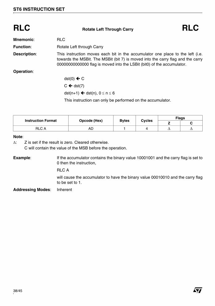
RLC Rotate Left Through Carry RLCMnemonic: RLC
Function: Rotate Left through Carry
Description: This instruction moves each bit in the accumulator one place to the left (i.e.towards the MSBit. The MSBit (bit 7) is moved into the carry flag and the carry00000000000000 flag is moved into the LSBit (bit0) of the accumulator.
Operation:
dst(0) ! C
C ! dst(7)
dst(n+1) ! dst(n), 0 ≤ n ≤ 6
This instruction can only be performed on the accumulator.
Note:∆: Z is set if the result is zero. Cleared otherwise.
C will contain the value of the MSB before the operation.
Example: If the accumulator contains the binary value 10001001 and the carry flag is set to0 then the instruction,
RLC A
will cause the accumulator to have the binary value 00010010 and the carry flagto be set to 1.
Addressing Modes: Inherent
Instruction Format Opcode (Hex) Bytes CyclesFlags
Z C
RLC A AD 1 4 ∆ ∆
38/45

ST6 INSTRUCTION SET
SET Set Bit SETMnemonic: SET
Function: Set Bit
Description: The SET instruction is used to set a specified bit in a given register in the dataspace.
Operation: dst (n) ! 1, 0 ≤ n ≤ 7
Notes:b. 3-bit addressrr. 1 Byte dataspace address*. C,Z not affected
Example: If register 23h of the dataspace contains 00000000 then the instruction,
SET 4,23h
will cause register 23h to hold 00010000.
Addressing Modes: Bit Direct
Instruction FormatOpcode (Hex) Bytes Cycles
FlagsSET bit,dst Z C
SET b,A b11011 FF 2 4 * *SET b,rr b11011 rr 2 4 * *
39/45

ST6 INSTRUCTION SET
SLA Shift Left Accumulator SLAMnemonic: SLA
Function: Shift Left Accumulator
Description: This instruction implements an addition of the accumulator to itself (i.e a doublingof the accumulator) causing an arithmetic left shift of the value in the register.
Operation: ADD A,FFh
This instruction can only be performed on the accumulator.
Note:∆: Z is set if the result is zero. Cleared otherwise.
C will contain the value of the MSB before the operation.
Example: If the accumulator contains the binary value 11001101 then the instruction,
SLA A
will cause the accumulator to have the binary value 10011010 and the carry flagto be set to 1.
Addressing Modes: Inherent
Instruction Format Opcode (Hex) Bytes CyclesFlags
Z C
SLA A 5F FF 2 4 ∆ ∆
40/45

ST6 INSTRUCTION SET
STOP Stop Operation STOPMnemonic: STOP
Function: Stop operation
Description: This instruction is used for putting the ST60/62/63 into a stand-by mode in whichthe power consumption is reduced to a minimum. All the on-chip peripherals andoscillator are stopped (for some peripherals, A/D for example, it is necessary toindividually turn-off the macrocell before entering the STOP instruction). Torestart the processor an external interrupt or a reset is needed.
Operation: Stop Processor
Note: *: C,Z not affected
Addressing Mode: Inherent
Instruction Format Opcode (Hex) Bytes CyclesFlags
Z CSTOP 6D 1 2 * *
41/45
ST6 INSTRUCTION SET
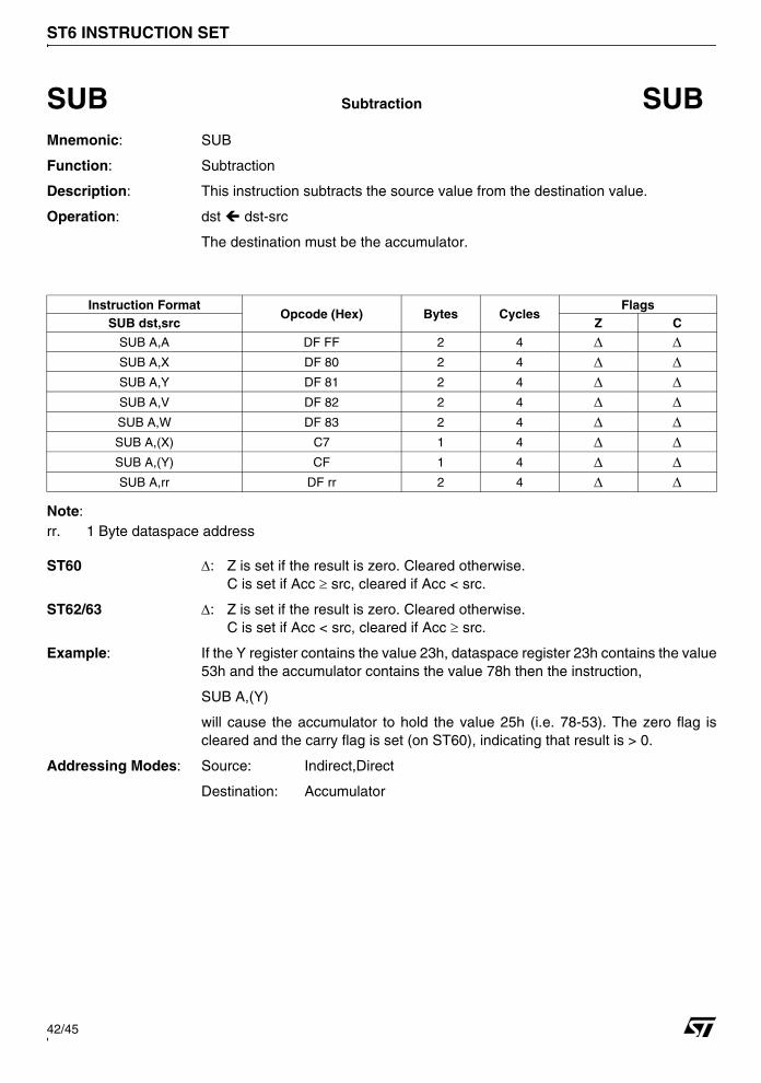
SUB Subtraction SUBMnemonic: SUB
Function: Subtraction
Description: This instruction subtracts the source value from the destination value.
Operation: dst ! dst-src
The destination must be the accumulator.
Note: rr. 1 Byte dataspace address
ST60 ∆: Z is set if the result is zero. Cleared otherwise.C is set if Acc ≥ src, cleared if Acc < src.
ST62/63 ∆: Z is set if the result is zero. Cleared otherwise.C is set if Acc < src, cleared if Acc ≥ src.
Example: If the Y register contains the value 23h, dataspace register 23h contains the value53h and the accumulator contains the value 78h then the instruction,
SUB A,(Y)
will cause the accumulator to hold the value 25h (i.e. 78-53). The zero flag iscleared and the carry flag is set (on ST60), indicating that result is > 0.
Addressing Modes: Source: Indirect,Direct
Destination: Accumulator
Instruction FormatOpcode (Hex) Bytes Cycles
FlagsSUB dst,src Z C
SUB A,A DF FF 2 4 ∆ ∆SUB A,X DF 80 2 4 ∆ ∆SUB A,Y DF 81 2 4 ∆ ∆SUB A,V DF 82 2 4 ∆ ∆SUB A,W DF 83 2 4 ∆ ∆SUB A,(X) C7 1 4 ∆ ∆SUB A,(Y) CF 1 4 ∆ ∆SUB A,rr DF rr 2 4 ∆ ∆
42/45

ST6 INSTRUCTION SET
SUBI Subtraction Immediate SUBIMnemonic: SUBI
Function: Subtraction Immediate
Description: This instruction causes the immediately addressed source data to be subtractedfrom the accumulator.
Operation: dst ! dst - src
The destination must be the accumulator.
Note:nn. 1 Byte of immediate data
ST60 ∆: Z is set if the result is zero. Cleared otherwise.C is set if Acc ≥ src, cleared if Acc < src.
ST62/63 ∆: Z is set if the result is zero. Cleared otherwise.C is set if Acc < src, cleared if Acc ≥ src.
Example: If the accumulator contains the value 56h then the instruction,
SUBI A,25
will cause the accumulator to contain the value 31h. The zero flag is cleared andthe carry flag is set (on ST60), indicating that the result is > 0.
Addressing Modes: Source: Immediate
Destination: Accumulator
Instruction FormatOpcode (Hex) Bytes Cycles
FlagsSUBI dst,src Z C
SUBI A,nn D7 nn 2 4 ∆ ∆
43/45

ST6 INSTRUCTION SET
WAIT Wait Processor WAITMnemonic: WAIT
Function: Wait Processor
Description: This instruction is used for putting the ST60/62/63 into a stand-by mode in whichthe power consumption is reduced to a minimum. Instruction execution isstopped, but the oscillator and some on-chip peripherals continue to work. Torestart the processor an interrupt from an active on-chip peripheral (e.g. timer), anexternal interrupt or reset is needed. For on-chip peripherals active during wait,see ST60/62/63 data sheets.
Operation: Put ST6 in stand-by mode
Note: *. C,Z not affected
Addressing Modes: Inherent
Instruction Format Opcode (Hex) Bytes CyclesFlags
Z CWAIT ED 1 2 * *
44/45
ST6 INSTRUCTION SET
Notes
Information furnished is believed to be accurate and reliable. However, STMicroelectronics assumes no responsibility for the consequencesof use of such information nor for any infringement of patents or other rights of third parties which may result from its use. No license is grantedby implication or otherwise under any patent or patent rights of STMicroelectronics. Specifications mentioned in this publication are subjectto change without notice. This publication supersedes and replaces all information previously supplied. STMicroelectronics products are notauthorized for use as critical components in life support devices or systems without express written approval of STMicroelectronics.
The ST logo is a registered trademark of STMicroelectronics.
All other names are the property of their respective owners
© 2004 STMicroelectronics - All rights reserved
STMicroelectronics group of companies
Australia – Belgium - Brazil - Canada - China – Czech Republic - Finland - France - Germany - Hong Kong - India - Israel - Italy - Japan - Malaysia - Malta - Morocco - Singapore - Spain - Sweden - Switzerland - United Kingdom - United States of America
www.st.com
45/45
Top Related