


Languages
Pages
Legal

Service.
For internal use only
All rights reserved, including the right to make technical changes.AUDI AGDept. I/VK-5D-85045 IngolstadtFax 0841/89-36367040.2810.62.20Technical status 11/00Printed in Germany
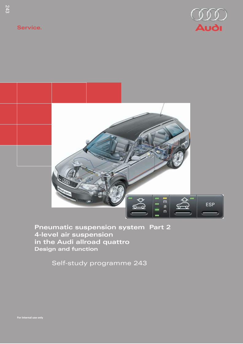
Pneumatic suspension system Part 2
4-level air suspension
in the Audi allroad quattroDesign and function
Self-study programme 243
243
24
3

2
The 4-level air suspension system in the allroad quattro is a logical development of the self-levelling system in the Audi A6. The principles of the suspension/air suspension system and the description of those system components which are identical in the 4-level air suspension system are described in SSP 242.The contents of this self-study program are supplementary to the contents of SSP 242.
The 4-level air suspension system in the Audi allroad quattro
Introduction
Designing a vehicle this perfect for on and off-road use sounds like squaring the circle.
Usually the strengths of an off-road vehicle are decided weaknesses when it comes to road use.A high ground clearance, crucial for rough terrain, gives the vehicle a correspondingly high centre of gravity.
243_001
243_002
243_003
When it comes to fast cornering, however, this is as disadvantageous as it is for driving stability at higher speeds. In addition, the air resistance is increased, which significantly affects fuel consumption.
In contrast, the shorter spring travel and the firmer running gear matching of an “on-road running gear” offer inadequate driving comfort off-road.
A variable ground clearance is the solution for all road use and it’s called
4-level air suspension
.
The air suspension realised in the allroad quattro is based on the familiar self-levelling system of the Audi A6.
3
Contents
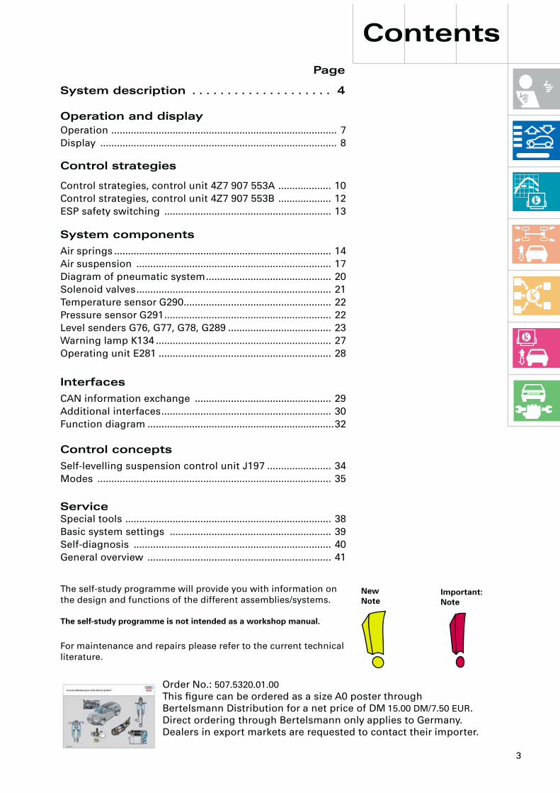
System description . . . . . . . . . . . . . . . . . . . . 4
The self-study programme is not intended as a workshop manual.
The self-study programme will provide you with information on the design and functions of the different assemblies/systems.
NewNote
Important:Note
Page
For maintenance and repairs please refer to the current technical literature.
Operation and display
Operation ................................................................................. 7
Display ..................................................................................... 8
Self-levelling suspension control unit J197 ....................... 34
Modes .................................................................................... 35
Control concepts
Service
Special tools .......................................................................... 38
Basic system settings .......................................................... 39
Self-diagnosis ....................................................................... 40
General overview .................................................................. 41
Control strategies
System components
Air springs .............................................................................. 14
Air suspension ...................................................................... 17
Diagram of pneumatic system............................................. 20
Solenoid valves...................................................................... 21
Temperature sensor G290..................................................... 22
Pressure sensor G291............................................................ 22
Level senders G76, G77, G78, G289 ..................................... 23
Warning lamp K134 ............................................................... 27
Operating unit E281 .............................................................. 28
CAN information exchange ................................................. 29
Additional interfaces............................................................. 30
Function diagram ...................................................................32
Interfaces
Control strategies, control unit 4Z7 907 553A ................... 10
Control strategies, control unit 4Z7 907 553B ................... 12
ESP safety switching ............................................................ 13
Order No.:
507.5320.01.00
This figure can be ordered as a size A0 poster through Bertelsmann Distribution for a net price of DM
15.00 DM/7.50 EUR
.Direct ordering through Bertelsmann only applies to Germany.Dealers in export markets are requested to contact their importer.

4
Description of the system
The vehicle level is determined separately at each axle side by means of 4 level sensors. Each air suspension strut is allocated a so-called air spring valve (transverse check valve) so that each axle can be controlled individually.
Front right air suspension strut
Rear left suspension strut with load-dependant damping.
Rear left vehicle level sender
Control unit
Pressure accumulator
Operating unit
Rear left suspension strut with load-dependant damping.
Air supply unit with: CompressorDischarge valveTransverse check valvesTemperature senderPressure sender
Rear right vehicle level sender
Electrical/pneumatic lines
Front left air suspension strut
Front left vehicle level sender
Front right vehicle level sender
The 4-level air suspension system is a fully-supporting level control system with conventional shock absorbers at the front axle and load dependent shock absorbers (PDC dampers) on the rear axle.
243_021

5
The 4-level air suspension system is designed as what is known as a pressure accumulator system.
The pressure accumulator system increases system availability, reduces noise development and protects the power supply.
One of the special features of the system is the ability to alter the ground clearance by 66 mm in 4 stages. The 4 stages can be controlled manually or automatically (see page 7 onwards).
The levels are designated as follows:
Level 1 = low level (
LL)
Level 2 = normal level (
NL
)Level 3 = high level 1 (
HL1)
Level 4 = high level 2 (
HL2)
Parking level
PL
= high level 1
High level 2 (HL2)
+41 mm from normal level
Ground clearance 208 mm
High level 1 (HL1)
+25 mm from normal level(=parking level)
Normal level (NL)
± 0 mm
Low level (TL)
-25 mm from normal level
Ground clearance 192 mm
Ground clearance 167 mm
Ground clearance 142 mm
241_063

6
Description of the system
• The 4 level stages can be controlled manually or automatically within defined limits (see page 8 onwards).
• Individual automatic functions or the entire system can be switched off via the control system.
• LEDs in the operating unit indicate the operating status and the control procedures to the driver.
• Pressure accumulator system for maximum comfort.
The newly developed fully-supporting air suspension system on all four wheels was designed specifically for the allroad quattro . As well as the advantages of air suspension-based self-levelling, as described for the A6 (see SSP 242), this system offers additional benefits.
• The 4-level air suspension is a sophisticated electronically controlled air suspension system at both axles. The system enables variation of the floor level by 66 mm and offers four defined height levels with between 142 and 208 mm ground clearance.
• Depending on the driving conditions and requirements you can select greater ground clearance or a low vehicle centre of gravity and a good c
w
value.
• The 4-level air suspension keeps the pre-set vehicle level constant, regardless of load and weight distribution.
242_067
7
Operation and display
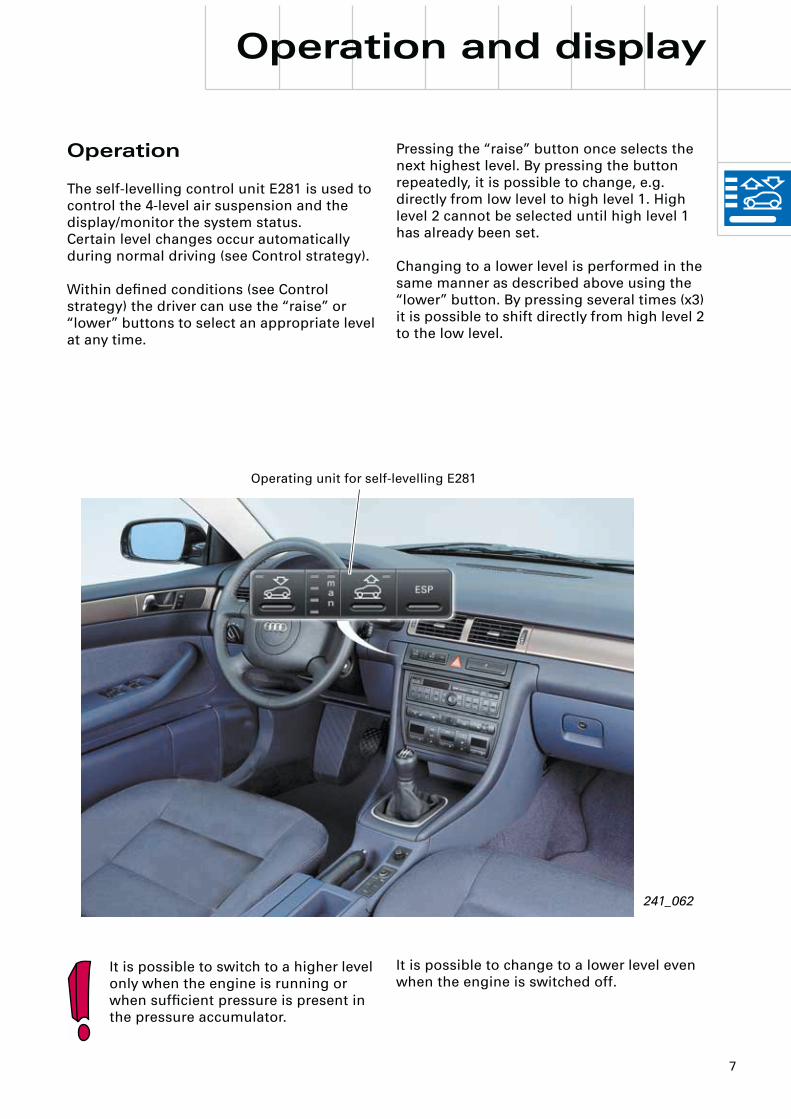
Operation
The self-levelling control unit E281 is used to control the 4-level air suspension and the display/monitor the system status.Certain level changes occur automatically during normal driving (see Control strategy).
Within defined conditions (see Control strategy) the driver can use the “raise” or “lower” buttons to select an appropriate level at any time.
Pressing the “raise” button once selects the next highest level. By pressing the button repeatedly, it is possible to change, e.g. directly from low level to high level 1. High level 2 cannot be selected until high level 1 has already been set.
Changing to a lower level is performed in the same manner as described above using the “lower” button. By pressing several times (x3) it is possible to shift directly from high level 2 to the low level.
Operating unit for self-levelling E281
241_062
It is possible to switch to a higher level only when the engine is running or when sufficient pressure is present in the pressure accumulator.
It is possible to change to a lower level even when the engine is switched off.

8
Operation and display
If the actual level deviates greatly from the reference level, this is indicated to the driver with flashing LEDs (according to a level change).
Significant deviations are:
– at least one axle level is below the next level down.
– both axle levels are above the next level up.
Display
The four LEDs which are arranged one on top of the other in the display zone illuminate continuously to indicate the current level status.
Only the control procedure which has been triggered by a level change (whether automatically or manually) is indicated by one or several flashing LEDs. Once the target level has been reached, the flashing changes to continuous illumination.
The LEDs in the “raise” and “lower” buttons indicate actuation and the control direction. If the LED flashes, a level request has been denied (e.g. if the driving speed is too high)
243_020
Lower button Raise button ESP button
Manual mode display
Display zone with 4 level-indicating LEDs
Actuation/control direction display Actuation/control direction display

9
243_022
243_023
243_024
243_025
Other button functions
Automatic switching
The so-called “manual mode” can be switched on or off by pressing the “raise” or “lower” button for at least 3 sec. The yellow LED marked “man” indicates to the driver that the vehicle is in manual mode. The automatic “parking level control” and “motorway mode” functions are deactivated in manual mode.
Switching off control system
The control system is switched on or off by pressing both level buttons for longer than 5 seconds.
When the control system is switched off, the LEDs in the operating unit for manual mode, both level buttons and the warning lamp K134 are illuminated.
The level-indicating LEDs show the level set. The corresponding LED is continuously illuminated.
A control system that has been switched off will be automatically switched back on again when the driving speed exceeds approx. 10 km/h (unless the lifting platform mode is recognised).
The control system can also be switched off using the diagnostic testers (see Workshop Manual).
It is often advisable to switch off the system during repair work (e.g. during axle measurement or if the pressure lines have been detached) in order to prevent the compressor from running unnecessarily.
Display example: Manual mode and NL
Display example: Raising from LL to HL1
Display example: Raising from HL1 to HL2
Display example: Lowering from NL to LL

10
If the vehicle is at high level 2, it will lower automatically to high level 1 at a speed of > 35 km/h. The system will respond to a request to shift to high level 2 only up to a speed of < 30 km/h.
At a speed of > 80 km/h in high level 1, the system will automatically lower the vehicle to normal level.. The system will respond to a (manual) request to shift to high level 1 only up to a speed of < 75 km/h.
During driving operation, no automatic raising to high level 1 or 2 is performed. It must be selected manually by the driver.
The parking level is an exception. In this mode the vehicle automatically rises to high level 1 once it has been parked and locked (see parking level control).
There are two control units currently in use, depending on the country.
The control strategies described below relate to the control unit 4Z7 907
553A.
The differences in control units with part numbers 4Z7 907
553B
are described subsequently.See also page 34, “Self-levelling control unit J197”.
Control strategies 4Z7 907 553A
Automatic lowering
As mentioned previously, the driver can select the appropriate level by actuating the “raise” or “lower” buttons.
The following preconditions relating to driving speed apply for high level 1 and high level 2.
Control strategies
0 35 80 120
0 5 35 70 120
Automatic lowering
Lowering processes
after 30 seconds
after 30 seconds
Raising processes
after 120 seconds
Raising to parking level
Immediate raising
Speed km/h
Speed km/h
243_026
LL
NL
HL1
HL2
LL
NL
HL1
HL2

11
Motorway mode
If the vehicle travels for longer than 30 seconds at over 120 km/h (vehicle is already at normal level), it will automatically be lowered to low level.
This reduces air resistance (saves fuel) and lowers the vehicle’s centre of gravity (improved driving dynamics).
PL (=HL1) is only cancelled when a driving speed of 80 km/h is exceeded (see automatic lowering) or when switching to a lower level manually.
If the vehicle is already in HL2 it is not lowered to parking level.
Manual mode
The motorway mode and parking level control functions are deactivated in manual mode (see Automatic switching page 9).
The vehicle rises automatically to normal level at the following speeds and time thresholds:
Vehicle speed Time
<70 km/h >120 seconds
<35 km/h >30 seconds
<5 km/h immediately
Parking level control
The parking level ensures that the vehicle is maintained at a suitable level after parking for a long period of time (normal volumetric reduction due to cooling or diffusion). It also facilitates entering and loading the vehicle and optimises the appearance of the stationary vehicle. The parking level corresponds to high level 1 (HL1).
The vehicle is set to parking level
– when the system is in run-on mode and the vehicle is locked from the outside.
– when sufficient pressure is present in pres-sure accumulator.
– when the system is not switched to manual mode.
12
Control strategies
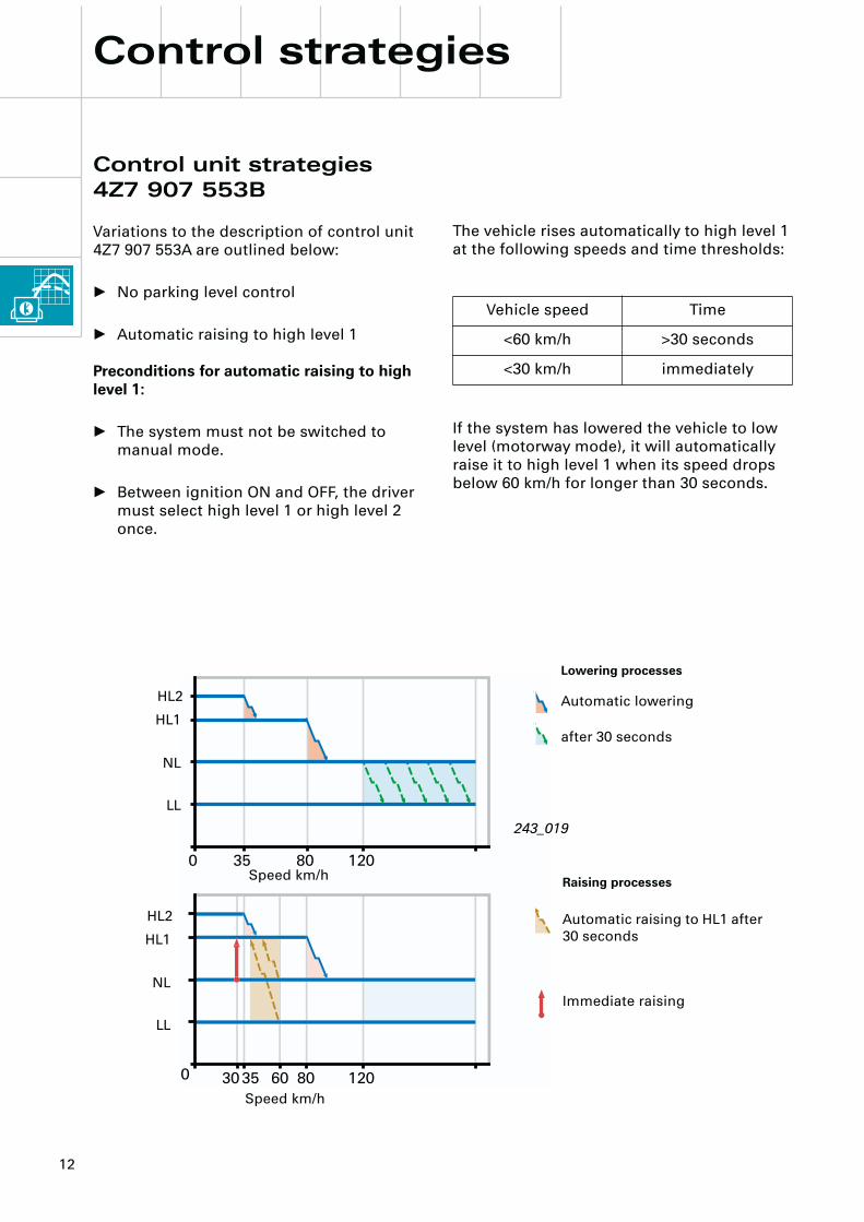
The vehicle rises automatically to high level 1 at the following speeds and time thresholds:
If the system has lowered the vehicle to low level (motorway mode), it will automatically raise it to high level 1 when its speed drops below 60 km/h for longer than 30 seconds.
Vehicle speed Time
<60 km/h >30 seconds
<30 km/h immediately
Control unit strategies 4Z7 907 553B
Variations to the description of control unit 4Z7 907 553A are outlined below:
• No parking level control
• Automatic raising to high level 1
Preconditions for automatic raising to high level 1:
• The system must not be switched to manual mode.
• Between ignition ON and OFF, the driver must select high level 1 or high level 2 once.
243_019
Automatic lowering
Lowering processes
after 30 seconds
Automatic raising to HL1 after 30 seconds
Raising processes
Immediate raising
Speed km/h
Speed km/h
LL
NL
HL1
HL2
LL
NL
HL1
HL2

13
If, for example, the vehicle is at high level 2 with active ESP influences and the driver accelerates sharply on a very winding route, speeds of > 35 km can be achieved in high level 2. In order to guarantee maximum safety in such driving conditions, ESP influences are automatically deactivated at a speed of > 70 km/h, despite the high centre of gravity of the vehicle (ESP-safety switching).Normal ESP functions are available again and the ESP warning lamp extinguishes.This ESP safety switching takes place as of 70 km/h at high level 2 and as of 120 km/h at high level 1.
There is no ESP safety switching at normal level or low level.
ESP safety switching
For technical reasons it is not possible to change levels/self-level during cornering. If cornering is recognised, no control functions are performed and control functions already running are interrupted. The target level remains stored and is reset when straight-ahead driving is recognised.
In the Audi allroad quattro it is possible to influence certain ESP functions using the ESP button. You can find further information about this in SSP 241, from page 67 onwards.
If ESP influences have been activated (via ESP button, ESP warning lamp illuminated), the transverse dynamics control (anti skid function) is passive (not during braking).
0 35 80 12070
ESP switching at high level 2
No self-levelling whilecornering
ESP switching at high level 1
Speed km/h
No self-levelling while cornering
243_027
Cornering is detected by the J197 self-levelling control unit by evaluation of the signals from the four level sensors.
LL
NL
HL1
HL2

14
The air springs
The front air spring is a new design.As on the rear axle, the air springs are combined coaxially with the dampers as a suspension strut. The rear air springs are identical in design and function to those of the Audi A6 with self-levelling.
Design
While in the case of the rear suspension strut, the connection/seal from the air spring (piston) to the damper is made via a double-seal bayonet connection, on the front suspension strut it takes the form of a single-seal N17 connector.The differences in design require a different assembly.
Front suspension strut
The assembly of the front air spring with the damper is carried out without lubrication. The N17 connector and the O ring must be absolutely dry and free from grease.Before assembly of the air spring, the O-ringis placed onto the second shoulder of the damper, ensuring an even perimeter. The air spring (piston) is positioned onto the damper and pushed together with adequate force. The O-ring is forced onto shoulder 3 by the movement of the piston, where it supports and seals the air spring.
System components
243_004
Installation
O-ring
O-ring
Air connection
15
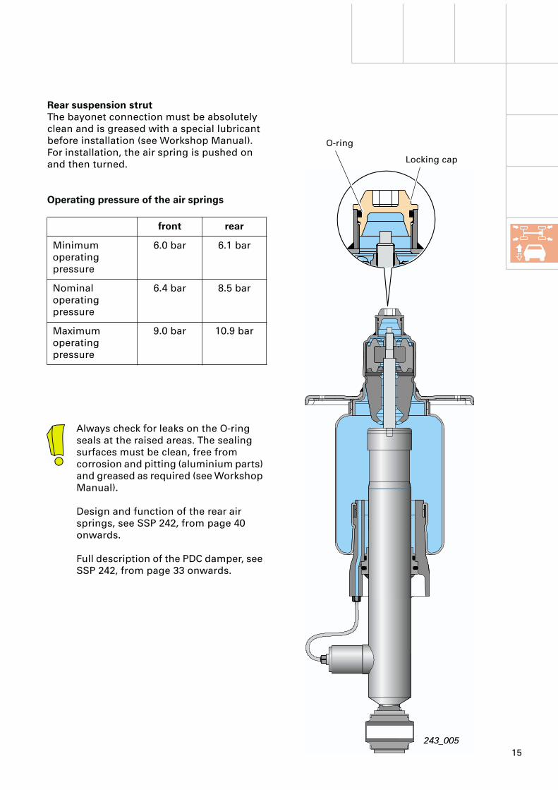
Rear suspension strut
The bayonet connection must be absolutely clean and is greased with a special lubricant before installation (see Workshop Manual).For installation, the air spring is pushed on and then turned.
Operating pressure of the air springs
front rear
Minimum operating pressure
6.0 bar 6.1 bar
Nominal operating pressure
6.4 bar 8.5 bar
Maximum operating pressure
9.0 bar 10.9 bar
Always check for leaks on the O-ring seals at the raised areas. The sealing surfaces must be clean, free from corrosion and pitting (aluminium parts) and greased as required (see Workshop Manual).
Design and function of the rear air springs, see SSP 242, from page 40 onwards.
Full description of the PDC damper, see SSP 242, from page 33 onwards.
243_005
O-ring
Locking cap

16
System components
243_006
243_007
Wrong Correct
Air springs must not be moved when pressureless because the air bellows cannot unroll on the piston and would be damaged.In a vehicle with depressurised air springs, the relevant air springs must be filled with the aid of the diagnostic tester (see Workshop Manual) before raising or lowering the vehicle (e.g. on a vehicle lifting platform or vehicle jack).
Warning:
The piston must not be touched during installation or transport of the complete suspension strut assembly as the piston can be easily pushed back when unpressurised.
If the sealing ring is pushed out of position (by the air spring pressure) the air spring will not be sealed correctly.
17
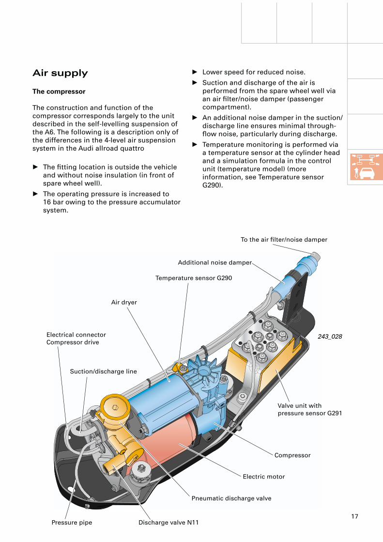
Air supply
The compressor
The construction and function of the compressor corresponds largely to the unit described in the self-levelling suspension of the A6. The following is a description only of the differences in the 4-level air suspension system in the Audi allroad quattro
• The fitting location is outside the vehicle and without noise insulation (in front of spare wheel well).
• The operating pressure is increased to 16 bar owing to the pressure accumulator system.
243_028
• Lower speed for reduced noise.
• Suction and discharge of the air is performed from the spare wheel well via an air filter/noise damper (passenger compartment).
• An additional noise damper in the suction/discharge line ensures minimal through-flow noise, particularly during discharge.
• Temperature monitoring is performed via a temperature sensor at the cylinder head and a simulation formula in the control unit (temperature model) (more information, see Temperature sensor G290).
Compressor
Valve unit with pressure sensor G291
Pneumatic discharge valve
Discharge valve N11
Air dryer
Temperature sensor G290
Additional noise damper
To the air filter/noise damper
Electric motor
Pressure pipe
Suction/discharge line
Electrical connectorCompressor drive

18
System components
A special mounting consisting of spiral springs and rubber damping elements prevents the transfer of vibrations to the bodywork.
You can find a description of the design and function of the compressor as well as the filling and discharging procedure in SSP 242.
243_008
In normal operation the compressor is allowed to run only when the engine is running.
Exceptions:
– Final control diagnosis– Basic system setting– In pre-run upon recognition of an
extremely low level
Mounting
243_009
Spiral spring
Damping element
Air filter/noise damper
Owing to the fitting location of the air filter/noise damper in the spare wheel well, it requires no maintenance.
19
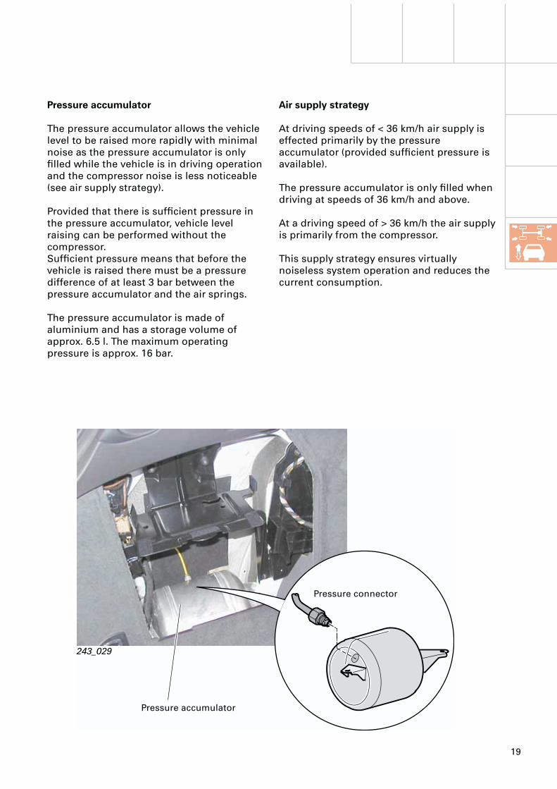
Pressure accumulator
The pressure accumulator allows the vehicle level to be raised more rapidly with minimal noise as the pressure accumulator is only filled while the vehicle is in driving operation and the compressor noise is less noticeable (see air supply strategy).
Provided that there is sufficient pressure in the pressure accumulator, vehicle level raising can be performed without the compressor.Sufficient pressure means that before the vehicle is raised there must be a pressure difference of at least 3 bar between the pressure accumulator and the air springs.
The pressure accumulator is made of aluminium and has a storage volume of approx. 6.5 l. The maximum operating pressure is approx. 16 bar.
243_029
Air supply strategy
At driving speeds of < 36 km/h air supply is effected primarily by the pressure accumulator (provided sufficient pressure is available).
The pressure accumulator is only filled when driving at speeds of 36 km/h and above.
At a driving speed of > 36 km/h the air supply is primarily from the compressor.
This supply strategy ensures virtually noiseless system operation and reduces the current consumption.
Pressure accumulator
Pressure connector
20
System components
p
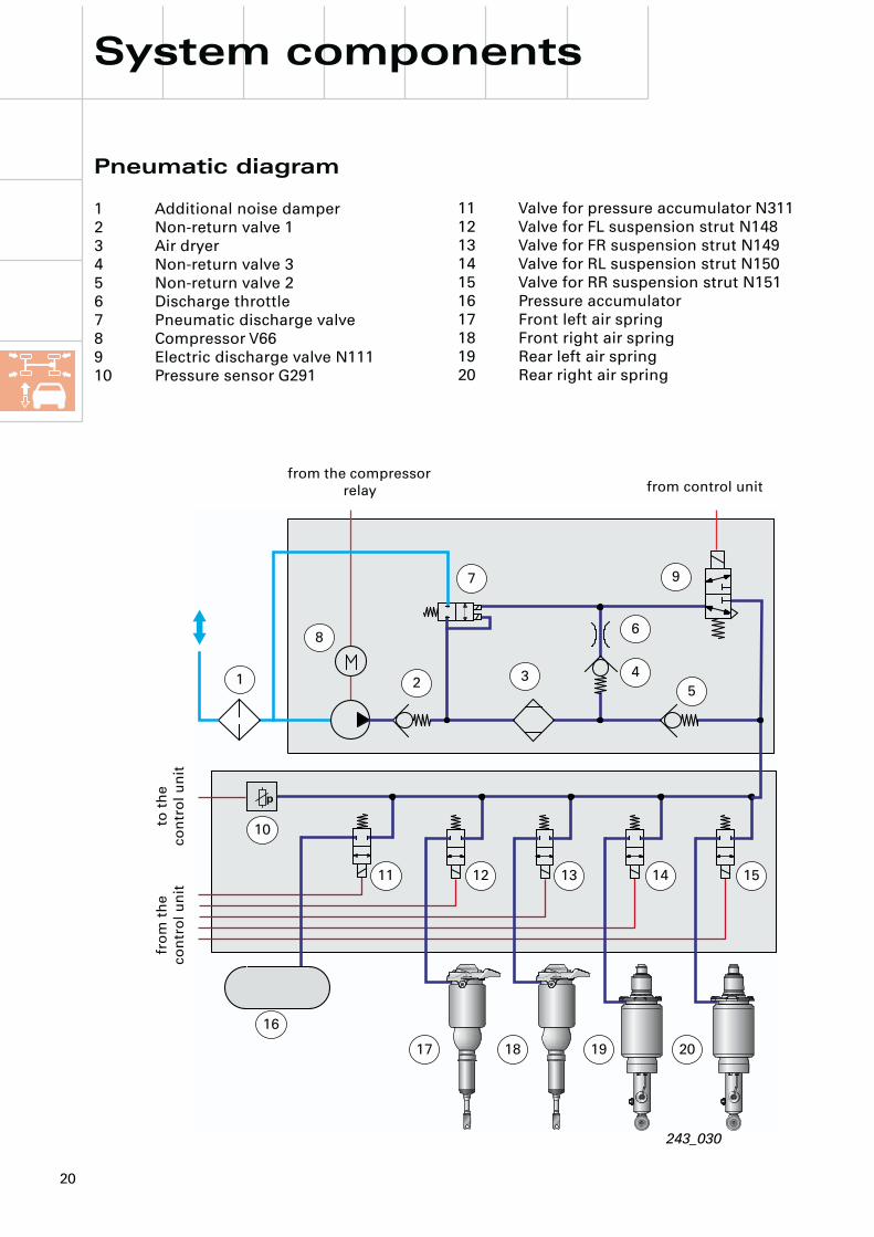
Pneumatic diagram
1 Additional noise damper2 Non-return valve 13 Air dryer4 Non-return valve 35 Non-return valve 26 Discharge throttle7 Pneumatic discharge valve8 Compressor V669 Electric discharge valve N11110 Pressure sensor G291
243_030
1 2 3 4
6
5
7 9
10
11 12 13 14 15
16
17 18 19 20
11 Valve for pressure accumulator N31112 Valve for FL suspension strut N14813 Valve for FR suspension strut N14914 Valve for RL suspension strut N15015 Valve for RR suspension strut N15116 Pressure accumulator17 Front left air spring18 Front right air spring19 Rear left air spring20 Rear right air spring
from the compressor relay from control unit
to t
he
co
ntr
ol
un
itfr
om
th
e
co
ntr
ol
un
it
8
21
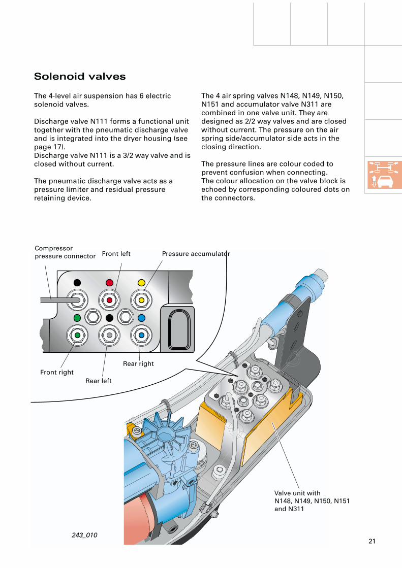
The 4 air spring valves N148, N149, N150, N151 and accumulator valve N311 are combined in one valve unit. They are designed as 2/2 way valves and are closed without current. The pressure on the air spring side/accumulator side acts in the closing direction.
The pressure lines are colour coded to prevent confusion when connecting.The colour allocation on the valve block is echoed by corresponding coloured dots on the connectors.
Solenoid valves
The 4-level air suspension has 6 electric solenoid valves.
Discharge valve N111 forms a functional unit together with the pneumatic discharge valve and is integrated into the dryer housing (see page 17).Discharge valve N111 is a 3/2 way valve and is closed without current.
The pneumatic discharge valve acts as a pressure limiter and residual pressure retaining device.
243_010
Valve unit withN148, N149, N150, N151 and N311
Compressor pressure connector Front left Pressure accumulator
Rear right
Rear left
Front right

22
p
Temperature sensor G290(Overheat protection)
To enhance system availability, temperature sensor G290 is attached to the cylinder head of the compressor.
A temperature model is implemented in control unit J197 which prevents overheating of the compressor while simultaneously utilising the maximum possible raising times.
For this purpose, the control unit calculates a maximum permissible compressor temperature based on the compressor running time and the temperature signal, and deactivates the compressor or prevents activation when defined limit values are exceeded.
System components
Pressure sensor G291
Pressure sensor G291 is integrated into the valve unit and is used to monitor the pressure in the pressure accumulator and the air springs. The information regarding accumulator pressure is required for checking the plausibility of the raising functions (see Pressure accumulator/control strategies, Page 19) and for self-diagnosis. The individual pressures of the air springs and pressure accumulator can be determined by means of appropriate control of the solenoid valves.
The measurement of individual pressures is performed during discharging or filling of the air springs/pressure accumulator. The pressures determined in this manner are stored and updated by the control unit.The accumulator pressure is additionally determined every 6 minutes (updated) while the vehicle is in driving operation.
The G291 transmits a voltage signal proportional to the pressure.
243_011
243_012
Temperature sensor G290
Pressure sensor G291 Valve unit
23
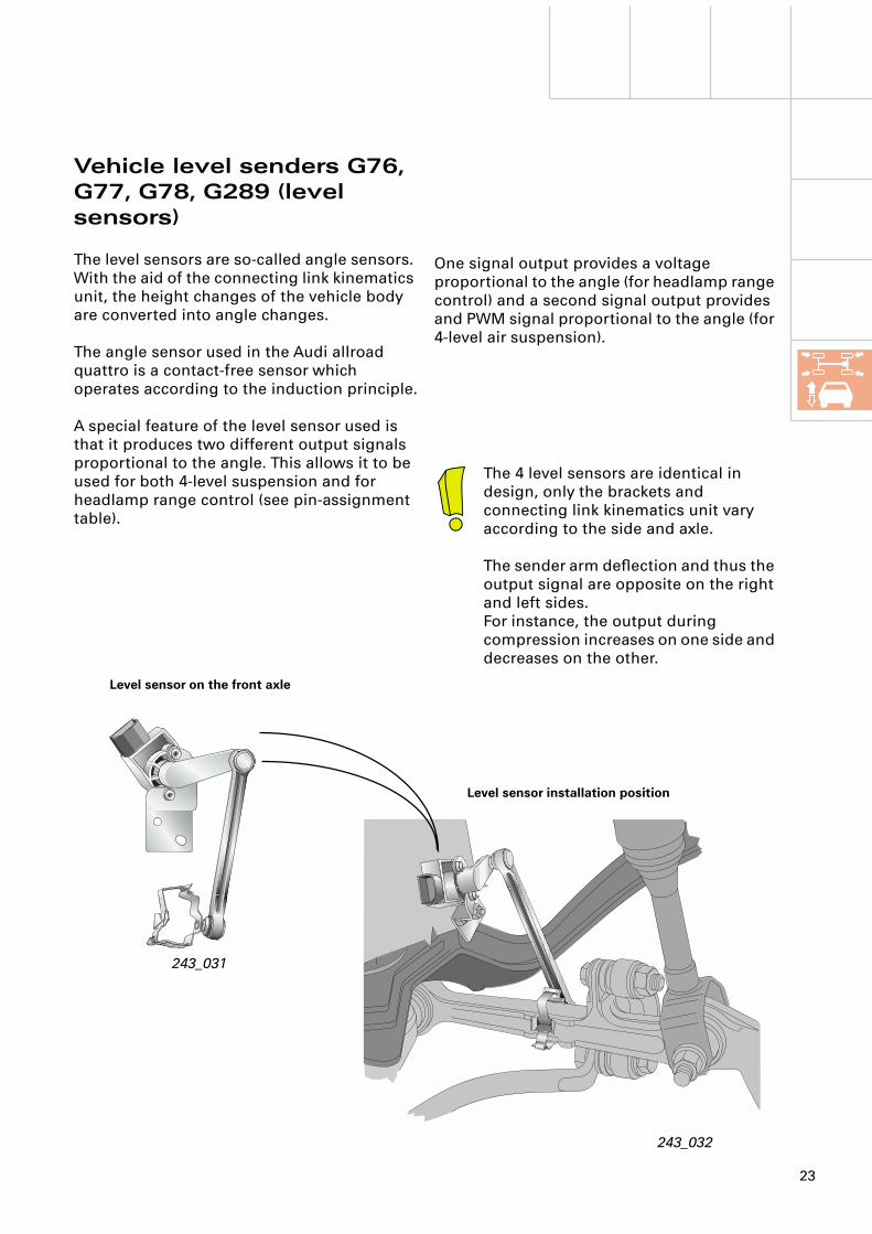
Vehicle level senders G76, G77, G78, G289 (level sensors)
The level sensors are so-called angle sensors. With the aid of the connecting link kinematics unit, the height changes of the vehicle body are converted into angle changes.
The angle sensor used in the Audi allroad quattro is a contact-free sensor which operates according to the induction principle.
A special feature of the level sensor used is that it produces two different output signals proportional to the angle. This allows it to be used for both 4-level suspension and for headlamp range control (see pin-assignment table).
243_031
243_032
One signal output provides a voltage proportional to the angle (for headlamp range control) and a second signal output provides and PWM signal proportional to the angle (for 4-level air suspension).
Level sensor on the front axle
Level sensor installation position
The 4 level sensors are identical in design, only the brackets and connecting link kinematics unit vary according to the side and axle.
The sender arm deflection and thus the output signal are opposite on the right and left sides.For instance, the output during compression increases on one side and decreases on the other.
24
System components
243_033
243_037
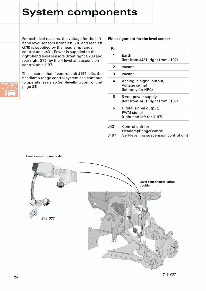
For technical reasons, the voltage for the left-hand level sensors (front left G78 and rear left G76) is supplied by the headlamp range control unit J431. Power is supplied to the right-hand level sensors (front right G289 and rear right G77) by the 4-level air suspension control unit J197.
This ensures that if control unit J197 fails, the headlamp range control system can continue to operate (see also Self-levelling control unit page 34)
Level sensor on rear axle
Level sensor installation position
Pin assignment for the level sensor
J431 Control unit for HeadampRangeControl
J197 Self-levelling suspension control unit
Pin
1 Earth(left from J431, right from J197)
2 Vacant
3 Vacant
4 Analogue signal output,Voltage signal(left only for HRC)
5 5 Volt power supply(left from J431, right from J197)
6 Digital signal output,PWM signal(right and left for J197)

25
The rotor consists of a closed conductor loop connected to the sender arm (rotates with the sender arm). The conductor loop has the same geometric shape as the receiver coils.
Construction/design
The angle sensor consists essentially of the stator and the rotor.
The stator consists of a multilayer circuit board comprising the exciter coil, three receiver coils and the control/evaluation electronics. The three receiver coils have an angular geometrical star shape and are arranged out of phase. The exciter coil is mounted on the back of the circuit board.
243_035
Operating lever
Conductor loop/rotor
Front of multilayer circuit board with view of the receiver coils
Circuit board connectors
Rear of multilayer circuit board with view of the exciter coil
Control/evaluation electronics

26
System components
Function
The exciter coil is subjected to an alternating current which produces an electromagnetic alternating field, the induction of which is penetrated by the rotor.
The current induced in the rotor produces a second electromagnetic alternating field around the conductor loop (rotor).Both alternating fields, from the exciter coil and from the rotor, act on the receiver coils and induce corresponding alternating currents in them.
While the induction of the rotor is independent of its angle position, induction of the receiver coils depends on their distance from the rotor and thereby on its angle position.
As the rotor, depending on its angle position, overlaps differently with regard to each receiver coil, their voltage amplitudes vary in accordance with the angle position of the rotor.
The evaluation electronics compensate the alternating currents of the receiver coils, amplify them and produce proportional output voltages for the three receiver coils (proportional measurement). After voltage evaluation, the result is converted into output signals for the level sensors and transmitted to the control units for further processing.
0
0
0
243_036
243_037
Exciter coil
Stator
Rotor
3 receiver coils
Conductor loop(induced current)
U1
U2
U3
Voltage amplitudes depending on the position of the rotor with regard to the receiver coil(example of a rotor position)
U1
U2
U3
Time
Time
Time
1st magnetic field at the exciter coil
2nd magnetic field in the conductor loop

27
Warning lamp K134...
... illuminates for one second when terminal 15 is ON (self-test).
... is constantly illuminated in the case of relevant system errors or when the system is switched off.
... is constantly illuminated during basic system setting and when basic system setting has not been performed successfully.
... flashes in the case of extremely low or high levels.
... flashes during final control diagnosis.
242_050
Warning lamp K134
As no magnetic materials are required, temperature and age cause only minimal variances in the measured values. Such variances are caused by a reduction in the strength of the magnetic field of permanent magnets over time or due to temperature changes.
Level sensors, summary
The advantages of the angle sensor are the proportional measurement process along with their contact-free and therefore wear-free operation.
The generation of ratios (proportional measurement) means that the output signal proportional to the angle is largely independent of mechanical tolerances such as distance changes, axle movement or inclination errors. Magnetic interference is also largely suppressed due to the generation of ratios.

28
F
F
F
F
F
S
F
S
S
F
3
1
7
5
2/25
2/50
2/49
2/05
2/04
2/01
2/02
9
10
4
8
System components
Control unit J197 transmits the information concerning the vehicle level and the system status back to the E281 via the K wire, whereupon the electronic unit actuates the relevant LEDs.
For self-diagnosis reasons, the “raise” button is designed as a redundant additional interface.
Operating unit for self-levelling E281
The operation and displays of the operating unit are described on page 7. In this section, the function of the operating unit will be described.
The interface to control unit J197 is performed by means of a data communication wire (K wire)An electronic unit integrated into the operating unit evaluates the signals from the level button and transmits these as a corresponding data protocol via the K wire to control unit J197.
243_013
The K wire between E281 and J197 bears no relation to the self-diagnostic K wire between J197 and the diagnostic testers.
Electronic unit
Control unit J197
Terminal 30Terminal 15
Raise button
K wire
Operating unit E281
Terminal 58s
Terminal 58d
to the ESP control unit
from the ESP control unit
HL2
HL1
NL
LL
man
High
Low
Lower button
ESP button
F = LEDs for functional illumination S = LEDs for switch illumination
29
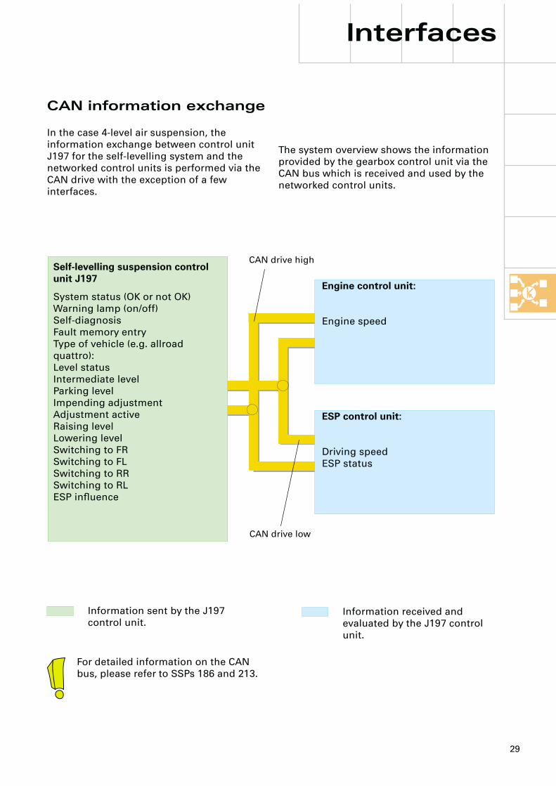
CAN information exchange
In the case 4-level air suspension, the information exchange between control unit J197 for the self-levelling system and the networked control units is performed via the CAN drive with the exception of a few interfaces.
Interfaces
The system overview shows the information provided by the gearbox control unit via the CAN bus which is received and used by the networked control units.
Information sent by the J197 control unit.
Information received and evaluated by the J197 control unit.
Engine control unit:
Engine speed
Self-levelling suspension control unit J197
System status (OK or not OK)Warning lamp (on/off)Self-diagnosisFault memory entryType of vehicle (e.g. allroad quattro):Level statusIntermediate levelParking levelImpending adjustmentAdjustment activeRaising levelLowering levelSwitching to FRSwitching to FLSwitching to RRSwitching to RLESP influence
CAN drive high
CAN drive low
ESP control unit:
Driving speedESP status
For detailed information on the CAN bus, please refer to SSPs 186 and 213.
30
The driving speed signal …
... is a square-wave signal produced by the dash panel, the frequency of which is changed in accordance with the vehicle speed.
... is required in the evaluation of the driving condition (stationary/driving mode) and thereby for selection of the control criteria (see “Control concept”).
The interface for the driving speed signal is redundant, as the information regarding speed is also transmitted by the CAN bus.
K wire
Communication for self-diagnosis between control unit J197 and the diagnostic tester takes place via the familiar K wire by means of conventional data messages.
The self-diagnosis K wire must not be confused with the K wire connecting operating unit E281 to control unit J197.
Power supply to the headlamp range control system
In the case of 4-level air suspension in the allroad quattro, the headlamp range control system voltage is supplied by the air suspension control unit J197. Further information can be found under Control unit J197 on page 34.
Additional interfaces
The door contact signal …
... is an earth signal from the control unit for central locking. It indicates that the door or boot lid/tailgate is open.
... serves as a “wake-up pulse” for transfer from sleep mode to run-on mode (see “Control concepts”).
Terminal 50 signal...
... signals actuation of the starter and is used to switch off the compressor during start-up.
If a low position is detected following a wake-up pulse, the compressor is activated immediately in order to allow the vehicle to drive off as quickly as possible.
The compressor is switched off during start-up in order to save battery power and ensure starting power.
The vehicle locking signal …
... is used as information for parking level control
... is an earth pulse coming from the control unit for central locking J429
... is not detected by the self-diagnosis. Parking level control is not performed if this signal fails.
Interfaces
The vehicle locking signal is not required for vehicles without parking level control (see pages from 10 onwards and 34 onwards).

31
1 2 3
1 2 3 7 8 4 9 6 5 13
BL NSL 31 58l RF BR 30 34 58r 31
10 11 12
The trailer operation signal …
..... comes from the F216 contact switch in the trailer socket.
When the plug is connected, contact switch F216 connects control unit J197 to earth.
See also “Trailer operation”.
Headlamp range control signal
As changing vehicle levels is axle-based (i.e. for both sides of an axle at once), this would produce a short-term visibility range reduction when driving at night.
For this reason, the allroad quattro is fitted with an automatic dynamic headlamp control system (also without gas-discharge headlamps). The automatic dynamic headlamp range control system maintains the light beam at a constant angle while the vehicle level changes.
In order to prevent irregularities in the road surface, such as bumps or potholes, from causing the headlamp range to alter unnecessarily, long reaction times are set when the vehicle is travelling at relatively constant speeds (little or no acceleration).
If level change takes place (e.g. motorway mode), the 4-level air suspension control unit J197 transmits a voltage signal to the headlamp range control unit J431.This activates the HRC immediately and controls the bodywork movements.
Level change process:
Raising - rear axle first, then front axle Lowering - front axle first, then rear axle
243_014
Trailer socket
to the self-levelling suspension control unit J197 (pin 2/10)
from the rear fog light switch
F216
32
Interfaces
pt°
M
1
AB
CD
2 3 4
IV III II I
5 6 7
9 12
8
M M
31
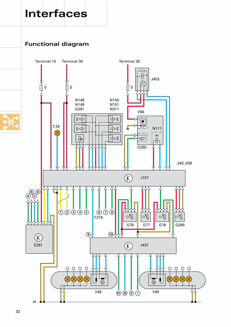
Functional diagram
Terminal 15 Terminal 30
T.34
Terminal 30
SSS
N150N151N311
N148N149G291
V66
G290
N111
J197
G76 G77 G78 G289
J431
V48 V49
E281
243_038
J403
F216
33
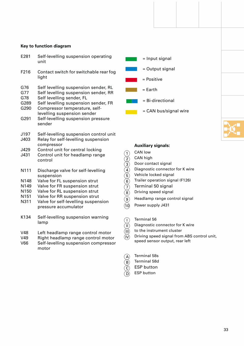
Key to function diagram
E281 Self-levelling suspension operating unit
F216 Contact switch for switchable rear fog light
G76 Self levelling suspension sender, RL G77 Self levelling suspension sender, RR G78 Self levelling sender, FL G289 Self levelling suspension sender, FR G290 Compressor temperature, self-
levelling suspension senderG291 Self-levelling suspension pressure
sender
J197 Self-levelling suspension control unit J403 Relay for self-levelling suspension
compressor J429 Control unit for central locking J431 Control unit for headlamp range
control
N111 Discharge valve for self-levelling suspension
N148 Valve for FL suspension strut N149 Valve for FR suspension strut N150 Valve for RL suspension strut N151 Valve for RR suspension strut N311 Valve for self-levelling suspension
pressure accumulator
K134 Self-levelling suspension warning lamp
V48 Left headlamp range control motorV49 Right headlamp range control motorV66 Self-levelling suspension compressor
motor
= Input signal
= Output signal
= Positive
= Earth
= Bi-directional
= CAN bus/signal wire
Auxiliary signals:CAN low
CAN high
Door contact signal
Diagnostic connector for K wire
Vehicle locked signal
Trailer operation signal (F126)
Terminal 50 signal
Driving speed signal
Terminal 56
Diagnostic connector for K wire
to the instrument cluster
Driving speed signal from ABS control unit, speed sensor output, rear left
1
2
3
4
5
6
7
8
I
II
III
IV
Terminal 58s
Terminal 58d
ESP button
ESP button
A
B
C
D
Headlamp range control signal9
Power supply J43110

34
However, all level sensors (left and right) are required in the air suspension system run-up and run-on mode (ignition OFF).
To allow the left-hand level sensors to deliver measured values in the case of the 4-level air suspension in the allroad quattro, power is supplied to control unit J431 (HRC) from control unit J197).This ensures that voltage is supplied to all level sensors when control unit J197 is active.
Self-levelling suspension control unit J197
The central element of the system is the control unit which, in addition to its control functions, enables the monitoring and diagnosis of the entire system.
The control unit detects the signal from the level sensors and uses it to determine the current vehicle level. This is compared with the reference level and corrected if necessary, depending upon further input variables (interfaces) and its internal control parameters (reaction times and level deviations).It differentiates between various control situations and controls them via the relevant control concepts (see Control concept).
Comprehensive self-diagnosis facilitates inspection and service of the system (see Workshop Manual).
There are two control units currently in use, depending on the country.Control units with the part numbers 4Z7 907 553A and 4Z7 907 553B have different control strategies (see page 10 onwards).A common control strategy for all countries (as for Index “B”) is planned for the future.
Control concepts
243_039
The system can be tested via the self-diagnosis or test adapter 1598/35. For further information, see “Service” chapter.
Address word 34
Power supply to the headlamp range control system
As previously described in the “Level sensors” section, voltage is supplied to the left-hand level sensors by the headlamp range control unit J431)
Headlamp range control requires neither run-up nor run-on times, so the voltage is normally supplied to control unit J431 via terminal 15 (ignition ON) (see function diagram, page 32).
35
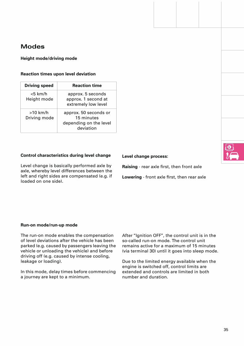
Level change process:
Raising - rear axle first, then front axle
Lowering - front axle first, then rear axle
Modes
Height mode/driving mode
Reaction times upon level deviation
Control characteristics during level change
Level change is basically performed axle by axle, whereby level differences between the left and right sides are compensated (e.g. if loaded on one side).
Driving speed Reaction time
<5 km/h Height mode
approx. 5 secondsapprox. 1 second at extremely low level
>10 km/h Driving mode
approx. 50 seconds or 15 minutes
depending on the level deviation
Run-on mode/run-up mode
The run-on mode enables the compensation of level deviations after the vehicle has been parked (e.g. caused by passengers leaving the vehicle or unloading the vehicle) and before driving off (e.g. caused by intense cooling, leakage or loading).
In this mode, delay times before commencing a journey are kept to a minimum.
After “Ignition OFF”, the control unit is in the so-called run-on mode. The control unit remains active for a maximum of 15 minutes (via terminal 30) until it goes into sleep mode.
Due to the limited energy available when the engine is switched off, control limits are extended and controls are limited in both number and duration.
36
Control concepts
The system can switch between sleep mode and run-on/run-up mode, triggered via the door contact signal, a maximum of 15 times. For the 15 subsequent wake-up procedures, the system switches to sleep mode after only 1 minute.
The system can then only be activated via terminal 15 and/or the speed signal.
Sleep mode
To minimise electricity consumption the control unit switches to “system idle” (sleep mode) after 15 minutes.
There is no level adjustment in sleep mode. “Wake-up” is primarily triggered by the door contact signal. If the door contact signal fails, the system is activated when the ignition is switched “ON” or by the driving speed signal.
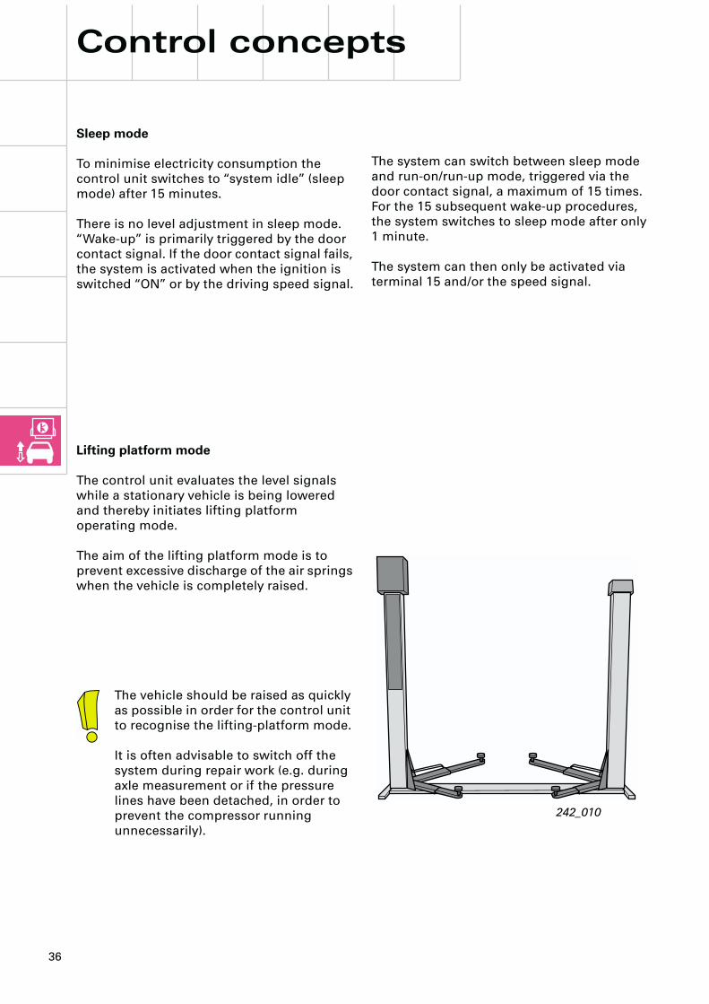
The vehicle should be raised as quickly as possible in order for the control unit to recognise the lifting-platform mode.
It is often advisable to switch off the system during repair work (e.g. during axle measurement or if the pressure lines have been detached, in order to prevent the compressor running unnecessarily).
242_010
Lifting platform mode
The control unit evaluates the level signals while a stationary vehicle is being lowered and thereby initiates lifting platform operating mode.
The aim of the lifting platform mode is to prevent excessive discharge of the air springs when the vehicle is completely raised.
37
In trailer operation, normal mode must always be selected and care must be taken that the system is switched to manual mode (e.g. no automatic switching to manual mode if trailer operation signal fails).
In difficult driving conditions, high level 1 or high level 2 can be selected, however, normal level must be selected before a driving speed of 35 km/h is exceeded.
Driving at low level or in automatic mode is not permitted.
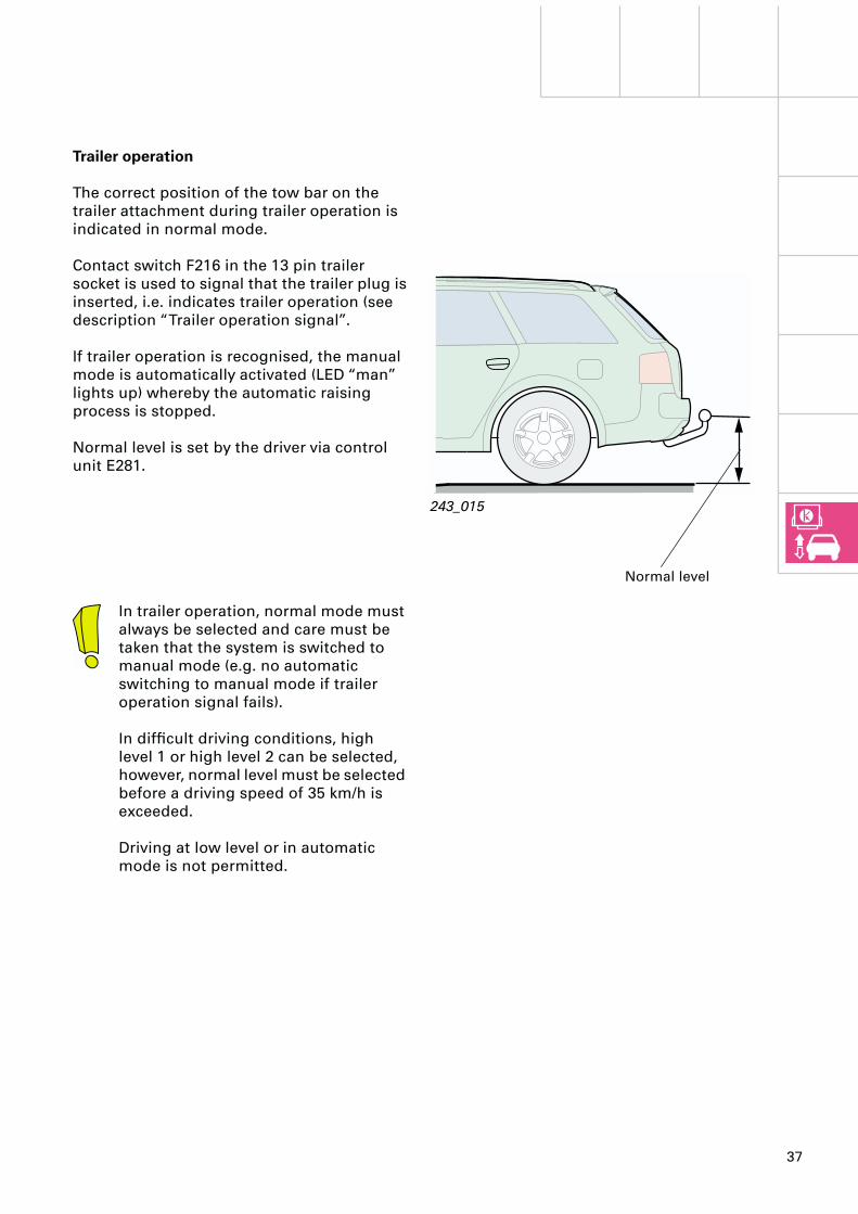
Trailer operation
The correct position of the tow bar on the trailer attachment during trailer operation is indicated in normal mode.
Contact switch F216 in the 13 pin trailer socket is used to signal that the trailer plug is inserted, i.e. indicates trailer operation (see description “Trailer operation signal”.
If trailer operation is recognised, the manual mode is automatically activated (LED “man” lights up) whereby the automatic raising process is stopped.
Normal level is set by the driver via control unit E281.
243_015
Normal level

38
Special tools
Adapter cable 1598/35 with test box 1598/14 are used for fault finding and function testing of sensors and signals of the 4-level air suspension system.
As the pin assignment of the test box is not compatible with the pin assignment of control unit J197, pin template V.A.G 1598/35-1 must be used.
Pin assignment is only possible by means of pin template V.A.G 1598/35-1.
Service
Due to the limited number of connections to test box V.A.G. 1598/14, not all interfaces in control unit J197 are wired.
243_016243_017
Adapter cable 1V.A.G 598/35
Pin template V.A.G. 1598/35-1
Test boxV.A.G. 1598/14

39
Basic system setting
The basic system setting of the reference level in the 4-level air suspension system is performed by inputting body-level measured values at normal level.
The measured value, the vertical dimension from the wheel centre to the wheel cut-out, must be input into the control unit using a diagnostic tester in function 10 “Adaption”. (Procedure, see Workshop Manual).
The codes serve to define the reference value for normal level (allroad quattro 402 mm). This means that design-specific values of the level sensors are adjusted for this dimension.
Due to the tolerances of the components involved, there is a certain deviation between actual (measured) and reference (defined) values.
By the inputting of the actual value, control unit J197 recognises a potential difference to the reference value. based on which the design-specific values from the level sensors are adapted.
Advantages of the measurement method:
• No influence of the correct basic setting due to …
... different tread depths and tyre pres-sures.... minor unevenness of the road surface.... different tyre sizes.
• Simple to perform.
Codes for the allroad quattro25500
Position Meaning
X0000 1 = Headlamp control not installed
2 = Headlamp control installed
0X000 5 = Reference height, front axle 402 mm
00X00 5 = Reference height, rear axle 402 mm
000X0 0 = Vacant
0000X 0 = Vacant
243_018
40
2 m
m
40
2 m
m

40
Self-diagnosis
Address word: 34 Self levelling suspension
Both generations of diagnostic tester (V.A.G. 1551/1552 and VAS 5051) are suitable for communication with the 4-level air suspension control unit.
Due to the limited capacity of the tester program cards, there are display text limitations in the case of diagnostic testers V.A.G. 1551 and 1552 (see. e.g. Workshop Manual, Self-diagnosis function 03, Final control diagnosis).
Service
198_039

41
Allroad quattro control strategies4-level air suspension + additional shift stage
020
3580
605
100
120
130
200
30
General overviewControl unit 4Z7 907 553A/B
ES
P s
afe
ty-s
wit
ch
ing
Au
tom
ati
c l
ow
eri
ng
Pa
rkin
g l
eve
lco
ntr
ol
v >
70
km
/h: E
ng
ine
in
terv
en
tio
n
v >
50
km
/h: A
co
usti
c a
nd
vis
ua
l w
arn
ing
in
lo
w r
an
ge
Air
su
pp
ly:
co
ntr
ol
pri
ma
rily
via
p
ressu
re a
ccu
mu
lato
r <
36
km
/h
Ve
hic
le s
pe
ed
v
in k
m/h
v <
30
km
/h: sh
ift
to l
ow
ra
ng
e p
ossib
le
Ad
dit
ion
al
sh
ift
sta
ge
Air
su
pp
ly:
co
ntr
ol
pri
ma
rily
via
co
mp
resso
r >
36
km
/hP
ressu
re a
ccu
mu
lato
r fi
lle
d >
36
km
/h
Mot
orw
ay m
ode:
Lo
we
rin
g:
>1
20
km
/h >
30
se
co
nd
sR
ais
ing
: <
70
km
/h >
12
0 s
eco
nd
s<
35
km
/h >
30
se
co
nd
s<
5 k
m/h
im
me
dia
tely
Man
ual
mod
e:-
no
pa
rkin
g l
eve
l co
ntr
ol
-n
o m
oto
rwa
y m
od
e-
au
tom
ati
c l
ow
eri
ng
fro
m H
L2
an
d H
L1
; E
SP
sa
fety
-sw
itch
ing
re
ma
ins a
cti
ve
Au
tom
atic
mod
e:-
pa
rkin
g l
eve
l co
ntr
ol
(HL1
)-
mo
torw
ay m
od
e:
- a
uto
ma
tic l
ow
eri
ng
fro
m H
L2
an
d H
L1
.-
ES
P s
afe
ty-s
wit
ch
ing
LL
NL
HL1
HL2
243_040
Con
trol
un
it 4
Z7
907
553B
: A
uto
mat
ic m
ode:
-n
o p
ark
ing
le
ve
l co
ntr
ol
-a
uto
ma
tic r
ais
ing
to
HL1
<6
0 k
m/h
>3
0 s
eco
nd
s<
30
km
/h i
mm
ed
iate
ly

42
Notes

43

Service.
For internal use only
All rights reserved, including the right to make technical changes.AUDI AGDept. I/VK-5D-85045 IngolstadtFax 0841/89-36367040.2810.62.20Technical status 11/00Printed in Germany
Pneumatic suspension system Part 2
4-level air suspension
in the Audi allroad quattroDesign and function
Self-study programme 243
243
24
3