


Languages
Pages
Legal


DNA 5662D
k. TRANS-IONOSPHERIC SIGNALS;PECIFICATION FOR SATELLITE C3
kPPLICATiONS
tmospheric Effects Division
efense Nuclear Agency
ashington, D.C. 20305
31 December 1980
In-House Repcut for Period 1 January 1980-31 Decernber 1980
APPROVED rOR PUBLIC RELEASE;DISTRIBUTION UNLIMITED. I
I~~~~~~ T5,,.,o uI,,,o
Ju:L . ., f3l .,
• ,Prepared for
Director
DEFENSE NUCLEAR AGENCY
Washngton. D. C. 20305
81 7 13 082
Destroy this report when it is tio longerneeded. Do not return to sender.
PLEASE NOTIFY THE DEFENSF. NUCLEAR ACENCY,ATTN: STTI, WASHINGTON, D.C. 20305, IFYOUR ADDRESS 1S INCORRECT, IF YOU WISH TOBE DELETED FROM THE DISTRIBUTION LIST, ORIF THI ADURESSEE IS NO LONGER EMPLOYED BYYOUR ORGANIZATION.
C¢
• o, "

UNCLASSIFIEDSU6CUNTY CLASS5WICATION Of THIS PAGE WhM Det0 Eate) _________________
REPORT DOCUMENTATION PAGE NZAD ISRCTIONSIs.lphOR WUMUEN1 / . 60V? ACCKUSI4ON NO, 3. ftKCIPIK%; t.O* Wu~mSS.
r ~ ~ )10NA-56621) ~~4O 7
JA ,RM-jN0P1IC SGA PECIFICATION)FOR AMTELL 9!APPUICATIOS JaSe-1 e
7.1 TO8.~y~ COTAT00"l UMS11,11(i
Najor~eon A. 'Wittwer3 . P E R FO RM I N G O f G "h I Z A T I O N A E A D D R S P R GA'A 1 1 0
Atmospheric Effects DivisionDefense Nuclear AgencyWashington, D.C.. 20305______________
... ....... It COTOLN OPPICENIA*6 AND ADORES& 2.emO"O
PDirector 1 31 Dec 19801Defense Nuclear Agency 4". NUM89E1OW PAGESWashington, D.C. 20305 60
AU -I ONITORING AGENCY NMEU 0 AOOaESS(U 4111"&W deA. CW..OM.. "vo) IS-SCURITY CLASS. (.1 We oopwo
UNCLASSIFIED
____ ___ ____ ___ _ __ ___ ____ ___ ____ ___N/A
19. DISTRIU~tON TTMM . e~e'
Approved for public release; distribujtion unlimited.
'I,. GISYgT IouwaI SATIMIMY (*#a* 0640" *"oedi A. tow" M. 0* w$40s ham N9%eo.)
Scintillations Satellite C3
prop~gatiun Radar Prpagatioaistriatioais Fadi aq
__ ?Atran-ionospheric signial strijcturv secification is presented f r use i
satellite link design. fftitigation, anid testing proraffl. A detaileddiscussion of wethods to impleftnt the signal structures described by thespecificatioa is included.
DD via*WCOeemWaa

UNCLASSIFIEDWCUPWTy CLAIWPICATIOPa OP YMtis PAOC_(M m. Sam.
UNCLASSIFIEDIUjftYV CLhWAt&MMM G* TWAI PA69tob iM 5u

iti
PREFACE
The development of this signal structure specification grew out
Sof discussions between the author and Major Nick Alexandrow, then of the
Air Force Nuclear Criteria Croup Secretariate. I would like to acknowledgehis contributions and the assistance of Dr. Dannis Knepp, Hission Research
Corporation and Dr. Clifford P'rettio, Berkeley Research Associates inpreparation of this report.
.[7
I -
_ i
- - . . . . . . . -l. - --- _ _ _ _ _

TABLE OF CONTENTr
Section Page
PREFACE 1
LIST OF ILLUSTRATIONS 3
1. INTRODUCTION 5
2. SIGNAL EFFECTS FORMALISM 6
3. SIGNAL SPECIFICATION DEFINITION 10
4. SIGNAL SPECIFICATION IMPLEMENTATION 13
5. SUMAY 14
REFERENCES 15
APPE1DIX A - THE GENERATION OF DIGITAL REALIZATIONS OF THE CHANNEL 17IMPULSE RESPONSE FUNCTION
APPENDIX B - A RANDOM NUMBER GENERATOR FOR NORMALLY DISTRIBUTED 31C04PLEX NUMBERS
APPENDIX C - EVA.UATIONS OF THE GENERALIZED, DELAY, AND FREQUENCY 33POWER SPECTRUMS FOR f T41
APPENDIX 0 - PROPAGATION EFFECTS LINK SIMULATORS 37
APPENDIX E - CIRF, A FORTRAN . ". GENERATING SAMPLE DIGITAL 41REPRESENTATIONS OF THE CHAEL IMPULSE RESPO&SEFUNCTION
,!2
II
LIST OF ILLUSTRATIONS
Figure Page
0-1 Propagation Effects Simulator
0-Z Flat Fade Simulator 40
21
I-

SA TRANS-IONOSPHERIC3SIGNAL SPECIFICATIONSFOR SATELLITE C APPLICATIONS
S• 1. I NTRODUlCTI ON
; Proper des•ign of radio frequency syste•3 that must operate
', through structlured o? varying plasmas require an accurate and easily
"mlmnbosgnlsviiao. hspcictoshlde"reasonable worst case" in that any system which operates wit.4 the
spociftodI signal can also operate tutdtor any likely disturbed condition.
The following %pecitfication is the result of a dedicated
• ~~prograza sponsored by the Oefense Nwlear Agenrcy mid the A•ir Force••We•apons Laboratory. Other majeor contributors vore the Naval Reseach
/•tAW riLbo'tory antd the Air Farce 4ophysics Lahoratory. The program i -aldw
•. ivestipatiotis in the Me¢hAnisms that cause strut~uremd pla*=aS. in the•i! •propagation of eloctrowtaguotic s~a~ls through strw~tured pl~smas. and
•:• •: a the effecots of sciatillatod or otherwis•e distorted ,iptIs on tyic¢ali- •*3tellite C linaks. Field experiments and aw~asurtown~t programs were
•T• executodi to vorify thoorvt',ieal plasta itrwture and radtio propagation
P prodtvtionti 4ft to etharactorie tho worphojty• of thle oailrat jotipo tvr.
taliýiti in tho resulting spw•fivatiott Are s-ovv'a ¢ard¢tia a
!:/•} ~this •¢~eto• cct• hilio•!raply iii incttMdo. 604-,r st~nmr; 4'hgS~iftformaitOft is atvailable la thoet¢as-liflod• ltiwaturv, It ii ftatedt.
:•* •couver. that thi• toi fia tiould W¢ adt•uatv for 1 satlel li~t, cS
-- '* *5 .
-4 I M m

2. SIGNAL EFFECTS FORMAL.ISM
Tle effects of a disturbed ionospheric channel are represented
by thoe .hannol impulse response function.
11(t) f dr h(t,t) S(t-T) (1)
S(t) = transmitted signal
C• 1R(t) = received signal (complex nmber representation)
h(t.t) - chatnel impulse response function
The specification chatnel impulse response function is
CO["~ ~~ c •' ~) €N(t)]
"h(t.t) t d(Af) '(t,Af)
(:arrier N- t )A/ _ (2)I C
Ca ight speed (U10 8 i/seO)
Spropagation putt. loitcth (in)
r v lassic~al decvtrou radittIft
K *t tota; cleetron coateat
for other tkhu ! iresla-r patlri:atlon, Equation I should be applied to eaeh
polar•:ation state aztd N(t) used to calculate the Faraday rotation effects.
I
a II II I • • I • mN6

tI
2 2
4n(tj4) @X(OliKi(f.-dx02W(0)0 oxpt-0 (4)
is~ ~ a zeonmen erraly angle of arrialdo variance (rthad ).ioovra
00
tiqaton 3 assumes* that themtransmitpoer ispon the antenn a(xVis and that
The gentennai pattern is cylindrisai psymetri.o abou that axis. It'lthe
Threwa-tw has ampitud for tueaotie"s (away passum ip~rayleigh),u c then ~('i
It ~ ~ podc is ahr zer mea norall disribte ryuandpomriabi' with an aT coarinc

This represents the flat fade condition with respect to the symbol period.
T. For f T8l
a t 231 4 l2foxpj.. 4 t ft -¾ (i )2.2wt] ft- )2r
fa x ej4 ""2rLI( •.Q l w fto)2-2w'f)1 (7)
C" 2
where V (l.&
•.,C 1 • dely parame tr (Q.0.25)
For both equat•I•o 6 and 7
PEquation 7 Provides for ti4attillattot randaft delay or. @quivalently.froquoucy svleetive vffeits.
If the 4citttiltatioa threat cuitiof phsOfi~ tt~wly or
if theN@4v a*e nocititltat!-on. -at all. thoo
•m m mS
)[,I

whr%()i hu larg) sal 8(06() (9)t adUt iia-Or C4
(slow) variaticons.gf)i
NPletrbfdf ilia ICA( -fwft)
oftodt4fýý i
Unormal tdisftotrihof theib~ offrepresentingf thef rnsoncopnnt h

3. SIGNAL SPECIFICATION DEFINITION
In principle, a complete signal structure specification would
include all of the time/space variations possible for the parameters and
functions in Equation 2. In practice, it is sometimes sufficient to
specify extremum values or simple functions for the propagation quantities
or their derivatives accompanied by application rules. The following table
lists a minimum set of specification parameters.
TABLE 1. SIGNAL SPECIFICATION PARAMETERS
SPECIFICATION PARAMETERS
Maximum Values
Absorption, KA2
Energy Angle of Arrival Variance, 2,
Transmitter/Receiver Vehicle
dnzDynamics, n0,3
dt
Signal Decorrelation Time, T
d nNL7"- n=0,3
dt
Rayleigh Frequency, f
"Minimum Values
Signal Decorrelation Time, T0
"Frequency Selective Bandwidth, f0
10

Two nearly universal application rules apply to T and fe" For ,
where both a minimum and maximum is specified, the system must operate
over all intermediate values. Similarly, when a minimum f is0
specified, the system must handle all f from the minimum to the carrier
frequency. Exercising these ranges are recessary because the maximum
performance degradation may not occur at the extreme values of either
Sor f.0 0
The parameters to be specified are functions of the carrier
frequency, the propagation scenario, the link geometries, and the
"velocities of the system segments. If possible, the specification
should cover all of the possible signal variations realized by exercising
the above factors over their entire range. Meeting this specification
•4 with each link independently would provide the utlimate in survivability,
that is, a system that can survive any scenario or circumstance. If this
specification cannot be met, then a less severe specification may be
possible at some acceptable loss of performance. For example, in nuclear
environments, signal specifications are a strong function of the maximum4acceptable outage time. Accepting longer outages can often provide
r significant specification relief. Additional relief might be possible
for systems that have multiple links that penetrate the ionosphere at
widely dispersed points. Because of the inherent space diversity,
the specification would not have to cover the most severe case for
any link, but some reduced level of threat. Regardless of the reason,
however, any reduction in the specification results in some loss of
system applicability.
Methods to calculate the propagation parameters are describedin reference 1, excluding absorption, which is covered in reference 2.
Calculations based on these methods serve as the basis for developing
signal specifications. The first step in the specification development
process is to choose the threat environments. For natural enviroaments,K.•
11 11!: '4•
'1
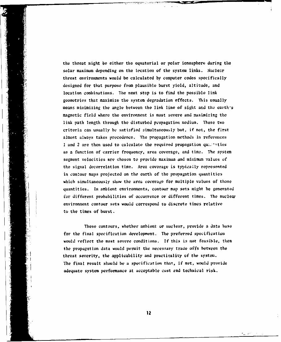
the threat might be either the equatorial or polar ionosphere during the
solar maximum depending on the location of the system links. Nuclear
threat environments would be calculated by computer codes specifically
designed for that purpose from plausible burst yield, altitude, and
location combinations. The next stop is to find the possible link
geometries that maximize the system degradation effects. this usually
omeans minimizing the anglo between the link line of sight and thI earth's
magnetic field where the environment is most severe and maximizing the
link path length through the disturbed p',opagation medium. These two
criteria can usually be satisfied simultaneously but, if not, the first
almost always takes precedence. The propagation methods in references
1 and 2 are then used to calculate the required propagation quw::."ties"as a function of carrier frequency, area coverage, and timz. The system
segment velocities are chosen to provide maximum and minimum values of
"the signal decorrelation time. Area covorage is typically represented
in contour maps projected on the earth of the propagation quantities
which simultaneously show the area coverage for multiple values of those
quantities. In ambient environments, contour map sets might be generated
for different probabilities of occurrence or different times. The nuclear
environment contour sets would correspond xo discrete times relative
to the times of burst.
These contours, whether ambient or nuclear, provide a data base
for the final specification development. The preferred specification
would reflect the most seve" conditions. If this is not feasible, then
the propagation data would permit the necesiary trade offs between the
threat severity, the applicability and practicality of the syste.
The final result should be a speeification that, if mot, wuld provide
adequate system perfoima•o at acceptable cost and te•hical risk.
12

• - -
'-21
SIGNAL SPECIFICATION IMPLDIENTATION
The disturbed signal effects represented by Equation 2 and
the specification parameters are applied twice during a typical system
acquisition. First, the signal specification is used during system
design to evaluate candidate design solutions. This evaluation is
frequently done using computer digital simulation and modeling techniques
which provide both simulated degraded signals and detailed descriptions
of the dynamic behavior of the candidate designs over all the specified
signal conditions rapidly and economically.
The signal specification is also applied during testing and
evaluation. At a minimum, the specification determines the range of
effects over which the system must be tested. At the other extreme,
the specification may define not only the parameter ranges but also
the exact form of the signuls. This latter circumstance oceurs when
a system, in its full operational configuration, cannot be exercised in
the maimum threat environments. For example, the mist severe natural
scintillations are coincident with the solar sunspot maximum which
occurs only once every eleven years. Systems that must operate in nuclear
degradeo etnvironments cannot be tested at all because of the 1963
Atmospheric Tct -in Treaty. In these instances, the best remaining
method is to degrad.v the satellite signals artificially by appropriately
:es.igned link simulators. by plaeing a simulator at one or more points
ing the oneratiowl system,. sting can be done limited only by the
accuracy of and -onfidence in thv signal specification.
Mioen link simulators are necessary for testing and evaluation,
4.ostioui arise over what wonstitutes a necessary and sufficient test
Sprogram. For example, is it necessary to includte all of the effects
reprosontod, by 4quation 2 in evoery toet 5imultaneoasly? Is it necessary
13

to test simultaneously every link in a system or even every link
individually? flow do you test a system to include the responses of the
operators as they react to degradation or, system links from propagation
or other simultaneous threats? On a longer term, is repeated testing
necessary to insure that the system hardware, the operational procedures,
and the operator responses remain adequate to maintain the requiredperforimance? Those and other similar issues need consideration for
each system tested. The answers to those questions, broadly known as
"compliance standards," should accompany the signal specification for
e•ch system to provide a completely defined test and evaluation program.
5. SUMMRY
The preceding sections have detailed the form of a signal3structure specification for application to satellite C systems. The
specification is intended as a design tool as well as a definition ofthe signal conditions in which the system must operate. Adequate
techniques exist to apply the specification both in computer simulation
during design and by a link simulator for test and evaluation.
Appendix A descvribes methods to implement specific realizations
of the channel impulse response function. Appendix b provides a brief
description of link iimulators.
II
|M

REFERENCES
1. Wittwer, Leon A., Radio Wave Propa aiton in Structured Ionizationfor Satellite Applications, DNA 5304D, (Contains a summary of thetechniques used to calculate signal structure parameters in disturbednatural or nuclear propagation environments and the development ofthe generalized power spectrum.)
2. Knapp, W. S. and Schwartz, K., Aids for the Study of ElectromagneticBlackout, DNA 3499H, 25 Feb 1975. (Compendium of seected graphs,charts, equations, and relations useful in the analysis ofelectromagnetic blackout caused by nuclear explosions.)
3. Knepp, D. L., Multiple Phase-Screen Pro9a•agtion Analysis for DefenseSatellite Communications System, -NA 4424T, (MR-C-R-332 -Missi-onResearch Corporation, September 1977. (Describes a numericalpropagation simulation technique in detail, and presents scintilla-tion calculations for X-band (7.5 GHz). Also see t-e followingthree reports for additional multiple phase screen propagationcalculation results.)
4. Wittwer, L. A., The Propagation of Satellite Signals ThrTurbulent Iedia, AFWL-eTR-77-183, Air Fo'ce Weapons Laboratory,January 1973. (Comprehensive treatment of effects of striatedionospheres on satellite signals. Calculations include effects ofvarious striation power spectral densities and scale sizes.)
5. Wittwer, L. A., et al., UHF PnrAaator. Effects in ScIntillatedEnvi ronmen ts, AFWL- TR- 76- 304, Air Force Weapons Laboratry ,Auqus t.- 77. (Describes propagation calculatiortal techniques and presentsresults for UHF satellite signals. Demonstrates that Rayleigh
Signal statistics are a reasonable worst case representation.)
6. Hendrick, R. Ut.. Piop#tion -f Microwave Satellite Signals ThroughStriated Media. MlA 441ZY TC-P-4334)' fissien Pesearect a- rpoir~aioh.•ptember -7Y. (Analyres resulýs of multiple phase screenpropagatioo calculations over a frequency range fr"o• 300 MHz to

*11

TEEETOAPPENDIX A
THE GENERATION OF DIGITAL REALIZATIONSOF THE CHANNEL IMPULSE RESPONSE FUNCTION
"Tito channel impulse response function is
2Trf i:(t) crNrt)h(tT)=A(t)exp - - i" (Af) ftAs )
2 I
Czrt N~)a N(t)exp -I f3 ~i21yAf t) rot.x j... (A-i)
where A(t) absorption and antenna loss
Sf carrier frequency
c =light speed
z(t) •propagation path length
ir classical ele.tron radius
X(t) N (t!.t R(t)
(t = slow trend total electron contentt
NR(t) ; random total electroo content
The generation of digital realizatior.s of Equation A-1. in"general, has three steps. First. A(t). K (t). and ýWt) are dig-rvtizvd.Next. samples of hi (t.f ad Nt(t) are valittlatod using Monte Carlo
techitques. rinally. the integral over Af is evaluated. Wit of the
complexity in generating those digital r epressntations lies in the randomsamapling of hs(t.Af) and O). mosot of this appondix will coaon etrate
171L'

onl these samp~ling techniques.
1the statistical proportics of It (tAf) are defined by
It(tAfv d-t df h1,1 xpinfii1t (A-2)
where (V,'r) is a zer-o men ormially distributed randoml variable with
its autocovari allc defined by
h.(f,f) 11 (V.',) U(A-Sb)
*Iwhere S(f) Dirac delta functionA
* '1 (ftt) generalized power spectrum
There are two distinc4t cases to be considered. firstt for
* flat fading defined by fQT"1 where f, is the frequency selvctive bain4-
width 4Wd T ii the symbol period1 the 4eneralized potter sip4ectruw 4s
Where Tis the signal decarrelation tiamt. uca-use of the delta
correlationt in delay. h, 1 ? is not a fuctjtjon of M- and the problv*
is reduced to geneoratIng a sequence th~t tA only a funcvtion of tiffW.
,.i
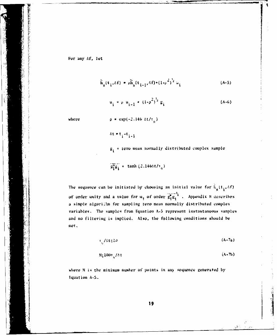
For any Af, lot
1 S(tia) Pi (ti, (A-5)
U. Ui p- (A-6)
where p exp(-2.146 A/t/)
At =t -t
gj zero mean normally distributed complex sampleiI
Tho sequen¢e can be initiated by choosing an iitigl Value for Io t11,At)
of order unity and a value for u of order 9 . Appoadix H•-!, 4sýribe%
a simple algori;twm for sampliag zero moan normally distributed 4waplox
vari4bahi. The sampleo from Equaton A-5 roprseont instataneous samples
and no tiltritag is ifplieC. Also, tho follotiog vanditions should bN
Met.
whtere, X ji thie tminimtai atn&-or of point!. int any sequence~ generatoct b~y
If Nquatio- A=-5.
* >9
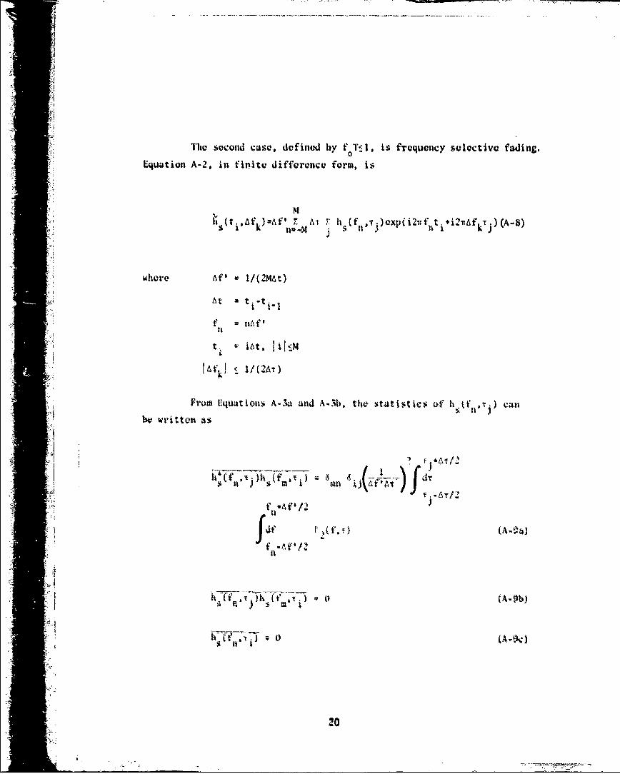
The second case, defined by f T.l, is frequency selective fading.
Lquatioon A-2, in finite difference form, is
.(tiAf )uAfl . A-t r h (f f ,i)cxp(i2rd fnti*i2IAfkT;) T A-8)
where Af' 1/(2MAt)
At tC t-
f n.f'
t jiýAt 1i?4
From Equ4tions A-.a and A-1b, the statistics of hIt f .t) canW¢ written as
Sif.tA/2
Sn ) • •Q j•t••
i>•~ a*AP/Zf
if (A --
'If
2.0

r
where, for fT< 1,
!2
34112 f~ 0 f)2 7u,.
e p f
4_ 2[ l221 1
f f 00 ,C~
C = delay prameter (-0.25)
Equation A-10 and related quantities are evaluated in Appendix C.Ceneraeii-t the hI to . 'k) consists of evaluating the hI(fa.t ),using
E|quations A-9, A-10, and Appendix 0 and then evaluating Fquation A-$.
For adequa-te statistical sampling and nuutrical resolution, it is.• lwteossal} t hat
U,
.tY At (A-lW)
~~ (A- 1bd)
'". - 4 (A-|lf)
Sf2,

where (Af k'Afk l. Condition A-lib is a tmautn Jinimum. Larger M ormultiple sequences are advisable. Equations A-lie and A-I1f prescribe
*1 the ranges of T and f in liquation A-I1 that include 95 percent Sf thetotal energy. The coefficients, It (f '•), are not necessary outsidethose ranges. Equation A.-lig and the 1' delendcnt teiz in Eiquation A-i Idreflect an estimate of the required delay range to handle disp|rsion.The integral in Equation A-9 can be evaluated to one percent with"trapezoidal integration with frequency and delay increments less than orequal to 0.03/-T and 0.03/f . respectively.
0
The represetitation used for the random port ion of the totalelectron content depends on the application. The first use of N11(t) in
iEquation A-I is in the carrier phase where it can degrade phase or
frequency acquisition and tracking. For phase effects
N (t. ),Aft" M(f#expti2nfnt ) (A-I2)
At' = t. ,t.
(V
, °
g(94') isa ero ýWafi aormlly distiributatd v-ariablv whotlk r-taiaiiag~t.~titrc bteindty

(Aft#),"/
(A-l13a)
(A- 13b)
whcve dfv g( t'
t'p Ray l iah fvwquonwy
lfnitiAl tt!ktimato,% for A t mid~ NOar
tt'Jf4t'R)(A. 144t
(A.14b)
for Vvrquwacy ttitýkjtjg. kqatuieto A-I." ýaftat 6v usied. lastya. lot

1,7- F -T T7777
Also,
I f'J Kn
_________T (f /r cg*(ff~gff) df0 C 0 f<fO
g n 2 3/2f -'n'-R' 0 (A- 16a)
(A ~ A /2 T T)1/
Af /2A0-o If'!>f n= (A-1l6b)
0n 0
0f'f
IYf=2f 1 /2
n R
W M
wheret -tf <1*(l11 n-
Aft l/2ff;)
0 14

The second use of N(t) in Equation A-1 is in the dispersive
phase. NR(t) can usually be omitted because the dispersive effects are
primarily determined by the mignitude of N(t) and not the time dependence.
The last use of N i(t) determines the group delay and group delay
rate which can degrade time synchronization if sufficiently large.
Equations A-15 and A-16 should be used with fR replaced by f,1"
f~R' El+(lOfcfR¶TOI)21 (A-17)
If simultaneous handling of the total electron content effects is
necessary, then Equations A-15 and A-16 are necessary. The substitution
of f should not be used. Unfortunately, the number of time incrementsT
necessary to span the time range can be very large. Exercising the range
of time may not be necessary in all cases. Some experimentation i5 often
indicated. Another problem with Equation A-15 is that the sum cannot be
evaluated with fast fourier transforms. Finally, multiple sequences of
NR(ti) should be used to test the adequacy of the sampling for either
I Equation A-12 or A-15.
The entire channel impulse response function is
r 1_ 2fCZ(ti) cr N(t) L
h(tiPT)=A(ti)exp i c i c (Af)k=-L (tiAfk)
?J
r cr N(t.)A 2 / t Jcr N(t.)(-8>: exp -1 o . i2wAfk j (A-18)
I~; ::,c cpex.
25

where Lzl/(2ArA(Af))
z(t. yr N(ti)t -- - ------ LAY
In principle, one only needs to insert the proper quantities
discretized to tho smallest increment ill time, delay, or Ak anid stum
over Af k. In practice, however, the wide range of tho delay and time
necessar-y to adequately sample the various functions make this impractical.
It is usually necessary to handle some of the terms indepenmdenitly,
particularly the total electron content and path length determined effects.
The channel impulse function is thereby greatly simplified.
h(tto ,iAn~tt) (t io (A -19)
where for f Tel
A ~ ~or for forf> (I ~ Al
AAA fortran program for generating It (t. *r. can be found in Appendix F.
Equation A-19 is implementable in a link simulator as descrtbed in &ppendix D.
An important consideration for implementing Equation A-18 or A-19
is the dynamic range required to resolve the amplitude. fluctuations, if
present. The amplitude of the channel impulse response f-unction at each
discrete delay is a Rayleigh distributed variable. Let the amplitude of
26

T- -- , -J "'
I_
h(t, Rj e distribution function for Ri. is
P(R1) oxp (A-20)
" "e .*AT/2
whore K-. f (1j ' (ft.)
--e/
E quation A-20 is easily invertablo to form probability statements aboutRi. Thus,
2
,-°+ .• ].p,+o,,°,,,,,t.,,,o . ,-<tn~r~abiitythait Rt 5Rb
exp 2 proba-bility that Rjt-R)
We require that the amplitude got exceed the dynamic range 99.8 percutkof the time. The upper and loer bowAds on the amplitude are,rpetcive•y
• U'R { /C -2(0.999
!.'27

where the probability that the amplitude exceeds the dynamic rango, 0.002,is equally split ibtween the limits. In decibels
-30dBý20 log - S.dB
Thus, 38.4 dl of dynamic range is required. If this is not feasible, theen
the loss of accuracy should be at the largest amplitudes. This is
because system performance is much more sensitive to amplitude fadeý thanto amplitude enlhancements.
The resolution in the amplitude and phase is a function of the
resolution of the real and imaginary components of h(ti,.)), The poorest
resolution occurs in deep fades at the smallest amplitude. The maximum
increrment is defined by requiring that successive values of either:componeat of h1ti .1 not vary by more than ten percent. This gives
adequate accuracy on the amplitude and resolves the phase to within six
degrees. If the component increment is fixed, then the smallest value mustbe used. The fixed increment for either component can be oxpressed as
one tenth of (R /,:)y . Variable increments are more desilrable
because they perit more efficient storage of coaponent data. They also
permit the use of logarithmie digital to atalog converters in link
simulators as described in Appendix D.
The total electron content effects neglected in Uquation A-19
cýan be bounded to deteýrminte necessary but noat siufficient Conditions for
successful sy!sitrf operation. The total electron content and its
drivatives ae gaussian dilstributed random variables with the followingmeaans and standard deviations.
28

... ..... 5 A j.- -*.w -- ** r
4Mkid --N
dm()( (A-21a)
Md m Sdtm dt
0 C
0 I) (2t (f / c
These statistical moments, when converted to moments of phase, doppler,
doppler rate, jerk, etc., allow perfonnance degradation estimates. These
statistics also determine the amount of time that any of the derivatives
exceed some value. As such, they provide the means for specifying various
system parameters consistent with some performaace requirement.
!The total electron content drives the dispersive distortion of
the signal waveform. As a measure of this distortion, we use the expoc-
tation value of the absolute value of the delay coordinate.
I
rI~d(AOOX .t~w)frI' dT ~f(fOX iýwf (A-22a)
ct'0 N(t)
iWi
Since the statistical wmean5 of the measure of distortion are proportional
to the mmenats of the total Olvctron reanent. perfomane Critweia can
Wb devoloped as a function of modulation and other system details. The
crie•ria should guarantet that the ratio of I"1 to T he sWall.
1 •29

The finite difference equations have been written in the lowest
order. This was done for simplicity aud to bc cousistcnt with fast
fourier transform algorith)m;. These algorithms can evaluate hquations
A-8, A-12, A-1i, and A-19 much more efficiently than conventional methods.
'I
:t
I 'I
30

- T IT
APPENDIX BA RANDOM NUMBER GENERATOR FOR
NORMALLY DISTRIBUTED COMPLEX NUMBERS
Let g be a normally distributed coaplex w•mber defined by
2
gig • 0(B-lb)
where P(I[gI) is the probability ditrtibution foi, the =pltitude of g. Leti bo a taitformly distributed random variablo ou tho interv-i. o•- Il.
A smpalo of g is calculatod by
03 1ki,
77.- "-rC--- --

'i
*1-

APPENDIX CEVALUATION OF THE GENERALIZED, DELAY,AND FREQUENCY POWER SPECTRUMS FOR f T<1
The generalized power spectrum is
r/ 112),
Iwhorv k -*
Cl -
* • frq44CY Ql(CtiV J bandwidth
t ;R s gt ld:rr l t ol t fk
A i o t u t o -.g o o ot o v a .i
C t ox
S33 • .

whn -7 _.9 .0 .9-7 -v
42
-I
wlwrg ;(~) ( ~ 0. 290 #().91 0.1701 124, 2 6 7 b
344

... .. ... • • . . -- , : • : ,. " ,• • ' --. . . .. •I I
"2 '
''exp .- 2 - • - (C-Sb)
wher F(t) a 0.7478Ss6t-0.0958798)t 0.348024 t
i Equation C-5 is accurate to aibou five figures. The frequency power-:: spectruma is defitaed as
f
g--IAi
,rl9
-~ I 3 i
I i~ :-i! 1 •I| I i • , , , ''P. ..... .. o J- ..

..-• ,i-'u•-. •., •:: -•-=T =:'' .-• *. .r - nq :- .. a i r ri I u r r
Frequently. integrals over the various powerd spectrums are
necessary as, for example, in Equation A-9. Trapezoidal integration with
the following integration increments is accurate to approximately one
prcent.
0 0.03/f (C-ha)
A• I 0.'03/f0o (C-I 1

APPENDIX DPROPAGATIOU EFFECTS LINK SIMULATORS
PigtiroPD-1show3 a geuneral implementation of a link s;imulator
which is the hardware analog of the channecl impulse resionsc *ufPtlwti
def ited byI
14(t) d~~.)~ )(0- 1)
Where S(t) atransmitted (input) 11ig14l
Lift) - roveived (output) sigutal
h~t~} 4atswl.impise VtspQott$ tuactiont
'the link simulator repntsents a di*cretiz4 ve~rsion of 0~-l whetv
(t) / * ti l
II/A$ I v di-eital to autao~l '40t'trrntOft
vetdta a4i Aprvadt L The 4~a rvi~&rjatsi Aftji,-44it A

E zyi i
aLwz
uj
(0
38I
044

are sufficient to support the digital to analog operation without any
additional filtering to suppress aliasing.
FigureD-2 shows a particularly simple link simulator for flat
fading and when all other effects are ignored or simulated separately.
The delay is used to get an independent noise source for the I
channel without an extra noise generator. The filters are single pole
providing in cascade the power spectrum represented by Equation 6. For
a RC filter, the time constant is
RC =T /2. 146 (D-3)0
The input/output can be at any frequency level.
IQ
Ft9
K'ii
Ki!,°

'4*06
CC
4'4JIV
UCCM
4mh
400
i0
APPENDIX ECIRF, A FORTRAN PROGRAM FOR GENERATING SAMPLE DIGITAL
REPRESENTATIONS OF THE CHANNEL IMPULSE RESPONSE FUNCTION
This appendix contains a fortran program to sample digital
representations of the channel impulse response function in Equation A-19
less the absorption and antenna loss terms. The coding is consistent with
Fortran IV with the exception of the dimension declaration in the fast
fourier transform subroutines (see comment in SUBROUTINE SETD list).
The methods used to generate the frequency selective sequences
are also used for the flat fade sequences rather than Equations A-5 and
A-6. The flat fade sequence generation is thus slower, but the sequences
generated are continuous from the last sequence term back around to the
first term, a very useful property for hardware testing applications.
The flat fade sequences are nevertheless consistent with Equation A-4.
The program tests the input for compliance with Equations A-Ila,
A-llb, A-11e, and A-11f. The recommended integration increments are also
enforced. The use of floating point variables for the channel impulse
response function output guarantees compliance with the stated phase and
amplitude resolution requirements on all known computer systems that
. support Fortran IV. The user is responsible for satisfying Equation A-lie.
The code provides time sequences of the impulse response function.
The first sequence centers on a delay of -0.04/E1O*DD/2 where F0 is the
frequency selective bandwidth and VD is the delay increment. The main
program loop over delay ends at statement label 70. Just prior to that
statement, the time sequence for thý- current delay is in the H array.
1(41+1-1) and H(I*I) represent the in-phase (real) and quadrature (iagioaary)
impulse response function components, respectively. The user is
41

responsible for providing the extra coding for disposing of the sequence
data. The data must be moved out of tha array before the loop returns to
calculate the next sequence.
Any remaining questions should be referred to
DirectorDefense Nuclear AgencyRAAE/Major Leon A. WittworWashington, DC 20305
A Autovon 221-7028Commercial 202/325-7028
The program was programmed and debugged on a lHeathkit H89
Computer system.
I
:41
i 42

PROGRAM CIRFCC THIS PROGRAM CALCULATES RANDOM SAMPLES OF THE SCINTILLATION CHANNELC IMPULSE RESPONSE FUNCTION AS DEFINED IN "A TRANS-IONOSPHERIC SIGNALC SPECIFICATION FOR SATELLITE Co.3 APPLICATIONS#" (ENCLOSING DOCUMENT)CC THE PROGRAM INPUTS AREC TAUO, SIGNAL DECORRELATION TIME(SEC)C FO, FREQUENCY SELECTIVE BANDWIDTH(HZ)C DT, TIME INCREMENT(SEC)C (THE TIME INCREMENT MUST BE LESS THAN OR EQUAL TO TAUW DIVIDEDC BY TEN)C DOt DELAY INCREMENT(SEC)C (THE DELAY INCREMENT SHOULD BE LESS THAN OF EQUAL TO THEC RELEVANT SYSTEM SYMBOL DIVIDED BY FIVE. IF DO IS GREATER THANC OR EQUAL TO SIX TENTHS DIVIDED BY FO, THEN ND(SEE BKLOW) ISC SET TO ONE AND THE FLAT FADE SPECTRUM IS USED)C NT. NUMBER OF DISCRETE TIMFSC (NT MUST BE A POWER OF TWO. NT MUST BE SUFFICIENTLY LARGE SUCHC THAT NT TIMES DT IS GREATER THAN OR EQUAL TO ONE HUNDRED TIME'.C TAUO)C ND, NUMBER OF DISCRETE DELAYSC (ND MUST BE SUFFICIENTLY LARGE SUCH THAT NO TIMES DD IS GREATERC THAN OR EQUAL TO SIX TENTH3 DIVIDED BY FO)C SEED* SEED FOR RANDOM NUMBER GENERATORC (SEED MUST BE AN ODD REAL NUMBER)C REQUIRED FUNCTIONS/ISUBO]JT INESC FLOAT (FIXED TO FLOATINO POINT CONVERSION)C SETD (INITIALIZES FAST FOURIWR TRANSFORM TABLE)C IFIX tFLOATING TO FIXED POINT CONVERSION)C DINT (DELAY INTEGRATOR)C PFAM (DFe(STANVARD [DEVATION OF FOURIER COEFFICIENT))C RANC'X (RANWIM 'F*(FyFdRER tXtEFFILtENT) GENERATOR)C PFT AND P[D 4PFA$T FOUJRIER TRAN$FQRM)C POWER (SIGNAL .POWER DENSITY AS A FUNCTION OF DELAY)C YCOR (COMPLEX $1NAL TIME Q RR"LATION F.W47TION)
DOUBLE PRECI$ION SEED
C TIT FOLLOWINO. PIMF-N$ION LIMITS ARE HINZM" VALUESC DIMENSION l'.hNTC
VIMFN,,ICN H(~40k',).)4tC QMMQN t[,T/NFP • pFP, ND.LP• •, ND,Ci
COMMON PDC.
C "T CiELAY FAkt4ETEIC
43

C READ AND TEST DATACC INPUT IS ON LOGICAL UNIT &C OUTPUT IS ON LOGICAL UNIT 2C OUTPUT(CRT) IS ON LOGICAL UNIT IC
CALL OPEN(6,,SYIiINPUT.DAT '1)
CALL OPEN(2,'SYI:OUTPUT.DAT 1)READ(6. 1000)TAIO.FOiDTDDNT.ND.SEED
1000 FORMAT(4E10.2*215,D1O.2)WRITEI2. 1001 )TAUOFO, LT.DDNT,NDSEED
1001 FORP¶AT1IXIP,27HSIONAL DECORRELATION TIME* *EIO.2/ IX*3114FREQUENCYI SELECTIVE BANDWIDTH- tEl0.2/lXI6HTIME INCREMENT- sElO.2ilXv17HDiEILAY INCREMENT- ,El0.2/lX,17HNUM8ER OF TIMESS oI5/lX#I6HN4NN8ER OF 0IELAYS- vI5/lX,6NSEED- D02O.12)
1010 FORMAT(IXZHRUNNINGIF(DT.LE.TAU0/I0.)OO TO 10WRITE(2. 1002)
1002 FOR"ATCIX*33HERROR-TIME INCREM~ENT IS TOO LARCESTOP
10 AMPmFLOAT(NT)NP-0
20 AMPmAMP/2.NP=NP. IIF(AMP.OT.1.)00 TO 20
IF(AMP.Erl.l.)O '10 3
100 FetJ MATE FjX.VERY I~MEN RANOEMe THEGATZN10TA
1q0 FQFPMAY I.4KRRE -_'A RW LS NT 06P
STOP
50 t(V0.T..4~lG0TO 6

jI
DVIl./(FL0AT(NT)*DT)C NFPuNUMBEIR OF FREOUENCY SUDINCREMENTS
NFPmIFIX( 33.*TA~l0*LF)+IC C'FPuFREOtIENCY SUB INCREMENT
DFPuOP /FL0AT(INFP)C NDPONIJMEER OF DELAY SUE'INCREMENTS,
C DDPwDELAY SUMICREMENTDOP-DP/FLOAT(NDP)
CC CALCULATE TIME SEQUENCES FOR EACH DELAYCCC DSTART IS THE BEGINNIN1O OF THE DELAY WINDOW. TWO PER CENT OF THEC SIGNAL ENERY ARRIVES BEFORE DSTART AND THUS IS NEGLECTED WHEN DSTARTC IS INITIALIZED TO -.04/FO..
* C
CIN TIALTI-. VARIFBLE FOR 9YATISTICAL TESTING. THE AWERA0E $IGNAL
C POWER AT EAr-H KiLAYiTHýE AVERAC-E VAR~IANCE OF THE FOURIER COEFFICIENT$C TIMES PD..2) AND THE TIME DECC*RKLATION PROPERTIES OYER ALL SEUENCE$C NEAR T"10O WILL OE TESTED.C
IC0RwIFIX~(TAIJO/DT)ICOR*IcoR*lCoR*1CORRPO.CORIWO.DO 70 IFI.ND
*R T.D (IS-10 111.
KwI.
AMPNI.Cc ZEOv F~vtjvmY Qv"KftcwT To, MAINTAIN ZERO MEAN ""b"EMC
U FA5I4aNI1IAL DELAV ImTEGroAyIoN NINT 6Ft*Ic
IRFtAMl(.f.,"ARTO F-:QT
v5PART~fART,9Y*9w
* 1 44

so K-K-2AMPaDFAM(D$TARTFSTART)CALL RANCOF(H(KhpH(K+1IhAMP)
CC USE FAST FOURIER TRANSFORM TO GENERATE FINAL SEQUENCEC
CALL PFT(HD)CALL. PDD(N)
CC TEST SIGNAL POWER IN SEQUENCE TERMS AiND ACCUMULATE DATA FOR TIMEC CORRELATION TEST. USE TRAPEZOIDAL !NTEORATION.C
TVARvt.0DO 90 .JICORL.2
CL1RR=CORR*H(K)*H(.J)*H(K*1 )oH(Je-1)Cf3RImCORI*H(K*1) *R(J)-tH(K)e*H(,1*1)
90 TVAR=TVArt.H(J).HGJ)*Hfj.1).HU.1*)AMPuZ.O*TVAR*LD.*02!FLOAT(L-ICCJII2)PSUMn.!5ePOWERIDSTART)T-LISTARTDO 100 J=1.NDPT-T*b'P"SEuPOWERt1 T
100 P$UM=F3UM*$NPSUMI P$iM'-*$5M1) OEIDP
T-D$TART*. 5'DDWR I TVf(2. 100?) T.AMP. P$1.'MI1000 FORMAT(1 /I X, JP. 7Ht'Ek-AY .Etf.:*/tlX.24HAVt:R~ sF $EOUJCN(E p1oIdtRu
1E1.2/I.2WTHO~tTICL EkYVENCE POW~kRa .tlkO.Ž)C
'1 CTHE H ARRAY NQ, IJ NTAtN< A $AMFt~ oXotm. lREPW~EN'TAT oN (IF TýIjC CHANNFLt,*u3 tM PtS ;E*PQN$EF FlUNlCFIt-N FC* A PELAY 0' 1AK't5.4.WC IN-PI4A$E ANDI ýIYAVRATUJRE Mi~l,TIPLIER`(THE REAL ANiD XMAkAINA8Y Pkf(15 O'F
C THE -4~Ja t$PVJL51 RE$P(tii F#UNCTION. RE$PEQTI tIL.V) ARE rEtVtKEi DY
1N*QS CONPCNEPJT MVLTIPIER -Hll%c MWLkftATU(C C('MVW4QENT MA."TIPItIE P Hl~tl?
e ~ ~ ~ ~ ~ ~ * It~ n'~sWCE$v A~ N TME:. THE tilER MUST rTWclt§E*C N
CTHE- kW~t~Ttt THE E34fA IN TK APRAY KFORE ORtEL-&. "0-1f
C THE NEKI [ELAY.LEV4. THEg t)"A I$ zTOREft i6ND L1ýrvR Vit(D SNC IIE'RA OERt'~M.jN HEE NTEfiTI(Ni W MUST Kt U'44D
C~ ~~A If~tCL aiT f NTIc~tATIQ mNEMCNTf,c

CORRu2. flCORRODDOO2/FLOATEL-ICOR.2)CORI-Ž.O.CORI ODD*'2/FLOAT(L-ICOA.2)Tm.5.FLOAT(ICOR-t ).DTAMPaTCOR(T)WRITE(2. IOO9)T,CORR.CORI,AMP
1009 FORMAT(/IX. 1P.24'HTIME DISPLACEMENT TESTED" *EIO.2/ IK.2&MCALCLILATEID DECORRELATIONs ~2E1O.2/lX.25HtHE0AETICAL CALCULATION" 4E10.2)WRITE(2, 1007)
1007 FORMAT(IK.IGHEND OF RUNENDFUNCTION DFAM (DSTART6*FSTART)
CC THIS FUNCTION CALCULATES DF TIMES THE STANDARD DEVIATtION OF THE RANDOMC FOURIER COPFFICIENT CORRESPONDINO3 TL" A DELAIY OF DSTART+.5e*t0 AND' AC FREQUENCY OF FSTART..5eDP'. THE VARIANCE OF THIS- Ft:URIEiR COEFFICIFENT
C IS THE ENERALIZ D WER SPECTRAL DENSITY INTEGRATED OVER -iLAY FUC DSTART TO rSTART.DD AND ONVER FREOUENCY FROMl FSTART TO FSTAWT*DjF.C INTEGRATION IS BY THE TRAPEZOIDAL RULE.cC ARGUMENTSC DISTARTaINITIAL DELAY(SEC)C FSTART=INITIAL FREOLIENCYtH?)C REQUIRED COMMON VAR lAStES,C NFP"NIMDER OF FREOLUENCY SUB INCREMENTSC DFP.FREOUENCY SL'E~ NCREMENT (hZ)C DDPmDELAY SUDtNCFAEMENT(S-:EC)C DD=DELAY INCREME-NTC DFMS=O. 500INT (DST3ART. F$'TART)
'1 FUNCiz 10C11 RiIREC DINT (DELAY INTEG5RATOR)C SORT (FLOATINO POINT SQUARE RC"T)C
TCOMMON /ITNP U.'..DO- ICo*IMOiN /ltFN4'UMS4
FvFSTART
DO 10 j;t.NVlP
10 FMtAtf
RE TuNNCNf'
C 7 J41tVtNIItN t*NTFL6TQT.IM E.VTHI FUNCTIONý iTIC44AYE3 V1f! A rEa~If WiwRIt~tx P
cCI~i~TTbCTII"~ tAIE4U( ~FADDVOSt~~~u, i
[jt 47
C FUFREtUENCVINZ)C RCOfJIFED COMPIQN VARIASLESC NO-FLAT FACE FLA.3C N01I.FLAT FADINCIC ND.0T.I.FAE0UENCY SELECTIVE FADINGC NC'P-NUNBER OF DELAY SUBINICREMENTSC DDPmDELAY SUPWNREIMENYC FUNCTIONS, REOUIRFD
CPSOFIF (FLAT FADE SPECTR(UM
CTSTOFO FLAT.P FADINGO
EN10D fl.D
FwRETURNiYH~
R1~ETU PRN MTE
FtWiIOLN ps ION0C Q C ~E~t~~sIf.
c~~ V.*14**f-* Cise) VAMI
now
00 TO 50f
-k 00 TO SO
oz-1.313.expIGZ)50 PS3n2. 901 FPSRiC.TAUO.EXP(.5* C&I 02-TPVPDi*OZ/SORT(L'11)
RETURN4ENDFUNCTION PSOFFIF)
CC THIS F4JNCTFNI IS THE FLAT FADE POW.ER SPECTRUM. THIS FUNCTION IS NOTC THE GENERALIZED POWER SPECYRUMEFLINC.TION PS03) INTEGRATED OVER ALLC DELAY. A CLOSE APPROX IMAT ION HAS SEEN CHOSEN INSTEAD BECAUSE OF ITSC UTILITY IN SOFTWARE AND HARDWARE APPLICATIONS. WHITE NOISE FILTEREDC OV TWO SINGLE POLE FILTERS REPR"COCS THIS SPECTRUMCC AROD.'IMENTS,C FFRE,'XINCY(HZ)C REQUIRED COMMON VAR lAPLESC TAUO.SICINAL DECOARELATION TINEC
COMMION /PSO./Ct * TAUO.FC*PSDFF'I1.0644TALJ4)AU I.*.8.572o(F0TAUO.j 0*2 0#RETURNENDS(**OVTINE RANCOF(1R.XI.AlP)
CC THIS FUN4CTION &ETLUcNS A COMP~LEX RANDOM-' NUMB~ER. (IlkdI h WHIERE THE RES'LC AND IMAOINARY PART$ ARE TNQCFENfiNT ZCROt MEAN NtX(NALLY 0t5TRL0AJTDC RANDOM VARA"LE~S giagw WITHi A v0~IAuce OFc# t~a
C ARCW*¶ENT$C EFkiRETURNED kfkI1 RANDOýM SAMPV,&C U jETJNE PV3NAMY RANDOM '$AJ"WtEC AMk4Ct$AR RQ(T TWO vTjEl TNK VAkt-N4c~ QF IRAND1C k~iXtJR~tf FUNCTIONS;
C SORT tIIOTING1 PCIINT 5CQJAR? NOOTýC ALor) 4WakoTI~p FOITtm NoitUV4AI, +50:)e RAND (S3Az*iv Ct g t'NWOM sTf@JwtIQN "'ThgtEN U:MO ANDk QNi)C Cos RawC~ti CosIN COIEl
CNE
4fl4Mi'5 IN C " -AL&4t4D1tA)
j
C REPLACE THIS ALGLAITHM WIRTH THE BETTER ONE(PRECSUMABLY) ONt HIS 0OWN
C ARGUMENTSC I-DlUMMY ARGUMENC REWIRRED CO'.MMs.N VARIABLESC SEED-RANDOM NL'M9ER SEED41NITIAL VALUE MlUST BE O00)C REQUIRED FUNCTIONSC 01100 (DOUBLE PRECISION MOD FUNCTION)C
DOUr4LE POCCSION SEEDCOMMON /RAt4/$EEDSEENaDMODI( 4. 0I:'D43.O507e*SEED. 2.48435456*0*)
END2 FUNCTION POWERID)
CC THIS FUNCTION CALCULATES THE GENERALIZED POWER SPECTRUM AT A DELAY OFC D INTEGRATED OVER AL~L FREQUENCY.CC AROUMENTSC DaKDLAYCSEC)C REQUIlR!W COIMMON VAR IAinESC CI=LECLAY PARAMETERC FO*FRECUENCY $ELECTIVIE bANNWlTHC REC4flREQ FUNCTIOlkeC SORT (FLOATMN POINT SQVME ROOT)C AW" CFLOAT IN*- PtNT ABS'3QTC VALUE1C. KIP tFLOATIN POINT NATURAL EZPCAiNTIA.Lb
CP4MMC't /PSti/Ct.TAkJOFc'
TelR . 146*f I M.40YAic 09t ýýIfl fT Pi-stý
tF -.L.Q Q.tali' C
FTIQNI Iraw F34

C N~o.1 FLAT Fr,-TNOC NNO.. 1, FREOtE44CV SCLECTZVC FADMC REWUIRED FUINCTIONtSC EXP (FLC'ATINO P01ZNT NATURPA EXPONENTIAL)C ASS (FLOATMIS POINT ABSOLUAC VALUE J
COtIVON /PSD/CI .TAUO.FOCOMMON ,PAT/NAFP.OFP,NOP.D:PNO.DC
CC CHECKC FOR FLAT rFou1aC
(S ~IFIND.EQ.1)CO TO 10TCOrt-ExPC-1 VITAUO)*Z)RETURN
IC TCOR.2.146*.A3SITP/TA'JO
RETURNENDSUSROUTINIZ $TD(TAOL.NT)
C SUPROUTINES SETri. PF~t AND PQOD ACCC*1MPtLt1 THE PAST FOURIE.R TRANWQoflC ON A COMPLEX AR-RAY.C. CR AND CI WILL bC ViED AS A~ tHOR WAND1 TOC REPRESENT THE REAL AND ZMA&IjNAV PARTS OF C. LETC CR11 % Cfl*I-t)C ClI?) w C(I.Z)C DEFINE THE COREPND'NE IFTLCEN C. Cr.o "Dn (. THE REZ'4L7$ý AM,;C RETURNED IN TM6t C ARRAY. TheE NJ4P9CtR OW POINT$ f1) 9Wt TRAN5Pa\RP Vii IC NPC.**NT. TWE FAST WQ#ISER TkAN"bQRM k-AJ44iUS 4 TALl& kP4iiWC THE COMP-tL TA##. ARRAY. "MIdMU LP9IY ROk TheE Q AN AZ) t$A$
C DIMENSION C4N~tNlP).TAS6tNP)
CIftk.J) AT tKi QIATPJT Etv*,AlA THE U wet * I V"Q k TI>1 wNS?
C
C WCR*E THE COMPFlJ NINTATION *eA$ f' KEN b kPIfI LIMA.I. AND
c Me~c -ýtw UW004 I.t. 0.t.A(NDI. .t.L-T.Nlt I
ntf?-r*.IS fS4N ?.TNl~aIAt4, ýkjt.LtkD fr O ;-kfý1C 4
NY f~t&tti,4 SEct TAUS kEa9, N6NAt EWt CJ0.Cf
* ~ HM Y ZCnN~' ~J~CSIN 1* A& 4@ HE ~I~* N I,4c
c CetIStigvapon4

tiiIi
C IN THE ABOVE SUM, M IS PROPORTIONAL TO THE VARIABLE REPRESENTED BY THEC I INDEX. FOR EXAMPLE. IF (CR(I),CI(I)) IS A FREOUENCY COEFFICIENT,C THEN ZERO FREQUENCY IS REPRESENTED BY M EQUALTO ZERO AND I EQUAL TOC ONE. SIMILARLY, N IS PROPORTIONAL TO THE VARIABLE REPRESENTED BY THEC.C J INDEX.CC FAST FOURIER TRANSFORMS ASSUME CONTINUITY OF THE FUNCTION TO BEC TRANSFORMED AND THE RESULT AT I(OR J) EQUAL TO NP/2+1 WHICH REPRESENTSC THE EXTREMES OF M(OR N). THE FUNCTIONS ARE ALSO CONTINUOUS BETWEENC (CR(l),CI(1)) AND (CR(NP),CI(NP)).CC REQUIRED FUNCTIONSC FLOAT (FIXED TO FLOATING POINT CONVERSION)C MOD (FIXED POINT MOD)C COS (FLOATING POINT COSINE)C SIN (FLOATING POINT SINE)C
C THE ARRAYS IN SETD,PFT, PND PDD HAVE BEEN DIMENSIONED TO ONE' C INTERNALLY. THIS MAY NOT BE ALLOWED ON THE USER SYSTEM. IT MAY BE
C NECESSARY TO DIMENSION TO THE LIMITS IN THE MAIN PROORAM OR TO USEC VARIABLE ARRAY DECLARATORS.•i~i C ***~******#****************.*********************************4********.*
DIMENSION TABL(I)
COMMON /FFT/N2.NTI,NLDATA PI/3.1415926*36/NTI=NTN2=2**NTNL=N2-1NN=N212-1TPI=2.*PI/FLOAT(N2)TABL(1)=I.TABL(2)=O.DO 40 I=l,NN
ii• d=I+l
DO 20 N=INTIf=If÷I+HO+D(J,2)
20 ..IRj/2
TABL(K)=COS(TPI4FLOAT(II))
40 TABL(K+1)=SIN(TPI*FLOAT(II))RETURNENDfUDROUTINE PFT(CTABL)DIMENSION C(1),TABL(1)COMMON IFFT/N2P.NTINLNI=2N2vN2PDO I Iu-NTINNw-N2-N2
SA4

DO 2 J=2,N1,2NN=NN+N2+N2N3=NN+N2DO 3 K=2,N2,2N4-N3+KSTR=C(N4-1 )*TABL(J-1 )-C(N4)*TABL(J)STr-c(N4-1 )*TABL(J)+C(N4)*TABL(.J-1)N5=NN+KCCN4-1 )=C(N5-1 )-STRC(N4)=C(N5) -S~rC(N5-1 )=C(N5-1 )4STRI3 C(N5)=C(N5)+STI
2 CONTINUENI=NI'N1
I N2=N2/2RETURNENDSUBROUTINE PDD(C)
CC REQUIRED FUNCTIONSC MOD (FIXED POINT MOD)C
DIMENSION C(1)COMMON /FFT/N2,NTI INL.DO I I=1,NL
DO 3 N-1.NTI
3 J-J/2
7 IN-1+Ie-1
DR-CC IN)01-CC IN+I)C(IN)=CCIIN)
C(IIN)wDR
I CONTINUERETURNEND
53
DISTRIBUTION LIST
DEPARTMENT OF DEFENSE DEPARTMENT OF THE ARMY
SAssistant Secretary of Defense BMD Advanced Technology CenterComm, Cmd, Cont & Intell Department of the Army
ATTN: Dir of Intelligence Sys, J. Babcock ATTN: ATC-T, M. CappsATTN: ATC-O, W. Davies
Command & Control Technical CenterATTN: C-312, R. Mason Electronics Tech & Devices LabATTN: C-650, G. Jones U.S. Army Electronics R&D Command
3 cy ATTN: C-650, W. Heidig ATTN: DELET-ER, H. Bomke
Defense Communications Agency Harry Diamond LaboratoriesATTN: Code 480, F. Dieter Department of the Army
ATTN: DELHD-N-P, F. WimenitzDefense Communications Engineer Center ATTN: DELHD-I-TL, M. Weiner
ATTN: Code R123 ATTN: DELHD-N-RB, R. WilliamsATTN: Code R410, N. Jones ATTN: DELHD-N-P
Defense Intelligence Agency U.S. Army Communications CommandATTN: DB, A. Wise ATTN: CC-OPS-WR. H. WilsonATTN: DB-4C, E. O'Farrell ATTN: CC-OPS-WATTN: DC-7D, W. WittigATTN: DT-5 U.S. Amy Cominunications R&D CommandATTN: DT-1B ATTN: DRDCO-COM-RY, W. Kesselman
§l ATTN: HQ-TR, J. StewartU.S. Amy Nuclear & Chemical Agency
Defense Nuclear Agency ATTN: LibraryATTN: NAFDATTN: NATD U.S. Army Satellite Commn AgencyATTN: STNA ATTN: Document ControlATTN: RAEE
3 cy ATTN: RAAE DEPAITMENT OF THE NAVY4 cy ATTN: TITL
Joint Cruise Missiles Project OfcDefense Technical Information Center Department of the Navy12 cy ATTN: DD ATTN: JCMG-707
Field Command Naval Ocean Systems CenterDefense Nuclear Agency ATTN: Code 5322, M. Paulsoh
ATTN: FCPR ATTN: Code 532. J. Bickel3 cy ATTN: Code 5324. W. Moler
Field Command 3 cy ATTN: Code 5323. J. FergusomDefense Nuclear AgencyLivermore Branch Naval Research Laboratory
ATTN: FCPRL ATTN: Code 7500. B. WaldATTN: Code 4700, 1. Coffey
Joint Chiefs of Staff ATTN- Code 7550, J. DavisATTN: C35. Evaluation Office ATTN: Code 4780, S. OssakowATTN: C3S ATTN: Code 7950, J. Gooa
ATTN: Code 4187
Joint Strategic Target Planning StaffATTN: JLA Naval Telecomeunications CoftidRATTN: JLTW-2 ATTN: Code 341
National Security Agency Office of Naval ResearchATTh: B-3. F. Leonard ATTN: Code 420ATTN: W-32, 0. bartlett ATTN: Code 465ATTN: R-52, J. Skillman ATTN: Code 421
Under Secretary of Defense for Rsch & Engrg Strategic Systems Project OfficeATTN: Strategic & Space Sys (05) Deprttmcnt of the Navy
jATTN: 45P5z722. F. WimberlyW•CC5 System E•gineering Grg ATTNi: h•p,214JATTN4 J, foff ATTN: NSP.43
444A

DEPARTMENT OF THE AIR FORCE DEPARTMENT OF ENERGY ONTRPACTO.S
Aerospace Defense Cmomand Lawrence Livermore National LabDepartment of the Air Force ATTN: L-31, R. Hager
ATTN: DL, T. Long ATTN: Technical Info Dept LibraryATTN. L-389, R. Ott
Air Force Geophysics LaboratoryATTN: OPR, H. Gardiner Los Alamos National Scientific LabATTN: OPR-1 ATTN: D. SimansATTN: LKB, K. ChampionATTN: OPR, A. Stair Sandia National LabATTN: S. Basu ATTN: Org 1250. W. BronATTN: PHIPATTN: PHI, J. Ouchau DEPARTMENT OF DEFENSE CONTRACTORSATTN: R. Thompson
Aerospace CorpAir Force Weapons Laboratory ATTN: N. StockwellAir Force Systems Command ATTN: V. Josephson
ATTN: SUL ATTN: R. SlaughterATTN: NTYC ATTN: D. OlsenATTN: NTN ATTN: I. Garfunkel
ATTN: T. SalmiAir Force Wright Aeronautical Lab ATTN: J. Straus
ATTN: W. Hunt ATTN: S. %werATTN: A. Johnson
901 CorpAir Logistics Command ATTN: T. NeighborsDepartment of the Air For.e ATTN: L. Jacobs
ATTN: OO-ALC/MW. Pt. BlackburnBerkeley R~esearch Associates. Inc
Air University Library ATTN: J. WcrknanDep4rrtnent of the Air Forc6
ATTN: AUL-LSE Cornell UniversityATTN: M. Kelly
Assiitant Chief of STaff ATTN: D. Farley. JrStudies & AnalysLesDepartment of the Air Force ML. Inc
ATTN: AF/$ASC. C. Rightmnyer ATTN! J. MNrsh4ilATTN: Ak/SASC. W. Keaus
Uenorel Electric Co8'lltstic Missile Office ATTN- M. BortnerAir Force Systems Commni ATTN: A. HArcar
ATTN: MNNXti. J. AllenUfleetea Resw~ch Corp
Ele4tronic Systems Division ATTN: J. Garbl•fiaATTN: DCKC. J. Cl1trk ATTN: J. tse. Je
Foreign Technology 0ivision University of tllintoiAir Forze Syttems CWA•mied ATTN- SKe-rtty 5upoevisor foe K. vei
ATTN: P4115 44br'ayATTN: TQT5. B, Distlard tfsttiute for DefenSe AlAsieb
ATTN: J. bengsto"Heaogu4rters 50¢4e oiviiion ATTN. J. AeinAir Force Systemf Cewand ATTN: F. baLer
ATTN: SKY, C, Keinedy ATTN ii, WolfkaNATTN: SOA. 0. fe:I. r
JAYCORi$eadiju4?teri Space bivilioiR ATTN! J. ýWl I"Air favee Systens Cemand
5TN e W.ti ATTN
He:u rTTvs SpaT Divti.fATT Lt '.t SL e
At*¶ faftke 5yitfZ*5 cofw4m ATTN *. M SdtsofATTN: I. liut aTTNfyN. s,
ATTN, 6A5 tUratelegi '!it- eiwn.tnft
D..e Ien f tria Alf Forvie L ink~~it LippATT *FSAMl: I. iaecot
ATTN M A TATTN: UTt..T LiAf-,G`1 UO.ATTN: MO.~ T. i e ATTN. 0. %WILeAftht: DesATN 1 &~t"

. PARTMENT OF DEFENSE COTRACTORS Lconuedi DEPARTMENT OF DEFENSE CONTRACTORS LCOf udI
Mission Research Corp R & 0 AssociatesATTN; R. Hendrick ATTN: S. YOOnATTN; F. FajenATTN: 0. Sappenfield Rand CorpATTN: Tech Library ATTN: E. BedrozianATTN: R. Kilb ATTN. C. CraihATTN: S. GutscheATTN: R. Iogutch science Applications, Inc
ATTN: L. LinnonM tre Corp
ATTN: B. Adams Sci .,nce Applications. IncATTN: A. Kyumel ATTN: J. CockayneATTN: G. HardingATTN: C. Callahan SRI International
ATTN: A. BurnsPactfic-Sterra Research Corp ATTN: R. T.unoda
ATTN: H. Drode ATTN: W. ChesnutATTN: A. Leadabrand
Pennsylvania State University ATTN: C. RinoATTN: Ionospher• c Research Lab ATTN: N. Uaron
Physical Dynamics, Inc Sylvania .ys•tems GroupATTN, E. Frouw ATTIU: M. Cross
Physical Research. inc Technology Inttrnational CorpTTNM: R. Deliberls ATTU: W. iDoquist
ATTN: N. G#anmswegATTN: W. Wriqht k & 0 Assocxi.tesATTI: R. Lelevier ATTI: W. KarzAt
ATTN: B. GQabbardATTN: P. Ha•s
"* I
* I . • - - _ ..- ,.. • .• • . .: :•: • _ •• . . . . . ... .. . . .. . . ... . _ . .. - . •
*! •" '
S'•. " • • !. .. •• -,." •q fe , •-• •••- • -..... ••- -• " TT•; • •> • • - .. .....7
Top Related