


Languages
Pages
Legal


Total solder points: 159 Difficulty level: beginner 1o 2o 3o 4þ 5o advanced
4 channel recorder / logger
ILLUSTRATED ASSEMBLY MANUAL H8047IP-1
Hardware:
þ USB connected and powered. þ Four DC coupled input channels. þ Input resistance 1Mohm. þ Maximum samples per second : 100 þ Four input ranges, 3V / 6V / 15V and 30V. þ Sensitivity 10mV. þ Accuracy ±3% of full scale. þ Maximum input 30Vdc. þ Power and recording/diagnostic LED indication on unit. Software:
• Analogue trace or digital DVM readout. • 4 simultaneous channels recording. • Minimum / maximum sample hold function for DVM. • From 1 sec to 1000 sec per division. • Storage and recall of screens (full colour) or data. • Automatic recording option for long time recordings. • On screen markers for time and voltage. • DLL included for own development.
K8047

2
VELLEMAN Components NV Legen Heirweg 33
9890 Gavere Belgium Europe
www.velleman.be www.velleman-kit.com

3
1. Assembly (Skipping this can lead to troubles ! ) Ok, so we have your attention. These hints will help you to make this project success-ful. Read them carefully. 1.1 Make sure you have the right tools: • A good quality soldering iron (25-
40W) with a small tip. • Wipe it often on a wet sponge or cloth, to keep it clean; then apply solder to the
tip, to give it a wet look. This is called ‘thinning’ and will protect the tip, and enables you to make good connections. When solder rolls off the tip, it needs cleaning.
• Thin raisin-core solder. Do not use any flux or grease. • A diagonal cutter to trim excess wires. To avoid injury when cutting excess leads, hold the lead so they cannot fly towards the eyes. • Needle nose pliers, for bending leads, or to hold components in
place. • Small blade and Phillips screwdrivers. A basic range is fine.
For some projects, a basic multi-meter is required, or
might be handy
1.2 Assembly Hints :
⇒ Make sure the skill level matches your experience, to avoid disappointments.
⇒ Follow the instructions carefully. Read and understand the entire step before you perform each operation.
⇒ Perform the assembly in the correct order as stated in this manual
⇒ Position all parts on the PCB (Printed Circuit Board) as shown on the drawings.
⇒ Values on the circuit diagram are subject to changes.
⇒ Values in this assembly guide are correct*
⇒ Use the check-boxes to mark your progress.
⇒ Please read the included information on safety and customer service * Typographical inaccuracies excluded. Always look for possible last minute manual updates, indicated as ‘NOTE’ on a separate leaflet.
0.000
Assembly hints

4
1.3 Soldering Hints : Mount the component against the PCB surface and carefully solder the leads
Make sure the solder joints are cone-shaped and shiny
Trim excess leads as close as possible to the solder joint
REMOVE THEM FROM THE TAPE ONE AT A TIME !
AXIAL COMPONENTS ARE TAPED IN THE CORRECT MOUNTING SEQUENCE !
Assembly hints

I
P
E
SF
S
DK
N
D
G
B
F
NL
C
O
D
E
CO
DIC
E
CO
LO
RE
CO
DIG
O
DE
CO
RE
S
CO
DIG
O
DE
CO
L-
OR
ES
VÄ
RI
KO
OD
I F
ÄR
G
SC
HE
MA
FA
RV
E-
KO
DE
FAR
GE
-K
OD
E F
AR
B
KO
DE
CO
LO
UR
C
OD
E C
OD
IFI-
CA
TIO
N
DE
S C
OU
-L
EU
RS
KL
EU
RK
OD
E C
O
D
E
0 N
ero
Pre
to
Neg
ro
Mu
sta
Sva
rt
Sor
t S
ort
Sch
war
z B
lack
N
oir
Zwar
t 0
1 M
arro
ne
Cas
tanh
o M
arró
n R
uske
a B
run
B
run
B
run
B
raun
B
row
n B
run
B
ruin
1
2 R
osso
E
ncar
nado
Ro
jo
Pun
aine
n
Rö
d
Rø
d
Rø
d
Ro
t R
ed
Ro
ug
e R
oo
d
2
3 A
ranc
iato
La
ranj
a N
aran
jado
Ora
nssi
O
rang
e O
rang
e O
rang
e O
rang
e O
rang
e O
rang
e O
ranj
e 3
4 G
iallo
A
mar
elo
Am
arill
o K
elta
inen
G
ul
Gul
G
ul
Gel
b Y
ello
w
Jaun
e G
eel
4
5 V
erde
V
erde
V
erde
V
ihre
ä G
rön
Grø
n G
rønn
G
rün
Gre
en
Ver
t G
roen
5
6 B
lu
Azu
l A
zul
Sin
inen
B
lå
Blå
B
lå
Bla
u
Blu
e B
leu
B
lauw
6
7 V
iola
V
iole
ta
Mor
ado
Pur
ppur
a Li
la
Vio
let
Vio
let
Vio
let
Pur
ple
Vio
let
Paa
rs
7
8 G
rigi
o C
inze
nto
Gris
H
arm
aa
Grå
G
rå
Grå
G
rau
G
rey
Gris
G
rijs
8
9 B
ianc
o
Bra
nco
B
lanc
o
Val
koin
en
Vit
H
vid
Hvi
dt
Wei
ss
Wh
ite
Bla
nc
Wit
9
A
Arg
ento
P
rate
ado
Pla
ta
Hop
ea
Silv
er
Søl
v S
ølv
Silb
er
Silv
er
Arg
ent
Zilv
er
A
B
Oro
D
oura
do
Oro
K
ult
a G
uld
Gul
d G
uldl
G
old
Gol
d O
r G
ou
d B
CO
LOR
= 2.
..5

6
q J
1. Jumper
q C1 : 220nF (224, 0.22) q C2 : 33pF (33) q C3 : 33pF (33) q C4 : 100nF (104, 0.1, u1) q C6 : 100nF (104, 0.1, u1) q C7 : 100nF (104, 0.1, u1) q C8 : 100nF (104, 0.1, u1) q C9 : 100nF (104, 0.1, u1) q C10 : 100nF (104, 0.1, u1) q C11 : 100nF (104, 0.1, u1)
4. Ceramic Capacitors
C...
q R1 : 1K5 (1-5-2-B) q R2 : 3K (3-0-0-1-1) q R3 : 6K8 (6-8-0-1-1) q R4 : 27K (2-7-0-2-1) q R5 : 91K (9-1-0-2-1) q R6 : 1M (1-0-0-4-1) q R7 : 91K (9-1-0-2-1) q R8 : 1M (1-0-0-4-1) q R9 : 27K (2-7-0-2-1) q R10 : 470E (4-7-1-B) q R11 : 6K8 (6-8-0-1-1) q R12 : 27K (2-7-0-2-1) q R13 : 27K (2-7-0-2-1) q R14 : 91K (9-1-0-2-1) q R15 : 91K (9-1-0-2-1) q R16 : 1M (1-0-0-4-1) q R17 : 1M (1-0-0-4-1) q R18 : 1K5 (1-5-2-B) q R19 : 27K (2-7-0-2-1) q R20 : 6K8 (6-8-0-1-1) q R21 : 3K (3-0-0-1-1) q R22 : 3K (3-0-0-1-1) q R23 : 1K5 (1-5-2-B)
2. Resistors
R...
q R24 : 27K (2-7-0-2-1) q R25 : 1K5 (1-5-2-B) q R26 : 27K (2-7-0-2-1) q R27 : 6K8 (6-8-0-1-1) q R28 : 3K (3-0-0-1- 1) q R29 : 27K (2-7-0-2-1) q R30 : 1K5 (1-5-2-B) q R31 : 470E (4-7-1-B) q R32 : 1K5 (1-5-2-B)
q IC1 : 28p q IC2 : 14p
3. IC sockets. Watch the position of the notch!
Construction

7
Construction
q LD1 : 3mm ‘Red’ => Recording
q LD2 : 3mm ‘Green’ => Power ON
q J5 : USB B90
8. USB connector
10. LED’s. Watch the polarity!
LD1
CATHODE
30mm
q IC1 : VK8047 Programmed PIC16C745-IP ! q IC2 : TLV274IP
11. IC’s. Watch the position of the notch!
PIN 1
1
q ZD1 : LM385Z
5. Zenerdiode
q X1 : 6MHz
6. Quartz crystal
X...
q J1 : 2P (CH1) q J2 : 2P (CH2) q J3 : 2P (CH3) q J4 : 2P (CH4)
7. Screw connectors
q C5 : 4,7µF/ 50V
9. Electrolytic capacitors. Check the polarity !
C...

8
G DO NOT CLOSE THE HOUSING YET
& G DO NOT ATTACH THE FRONT STICKER YET
A. Installation :
• Install the software. If the necessary software is not inluded or if you want to check for updates, you can always download it for free from our Velleman Website www.velleman.be
• An installation wizard will guide you trough the installation procedure.
• By default the software is installed in the folder : ‘C:\Program Files\Velleman\Pc -Lab2000’
Software installation & test
12. Software installation and test
Fig 1.0
9
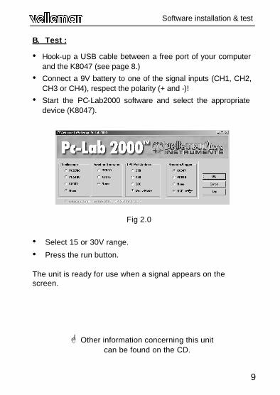
B. Test :
• Hook-up a USB cable between a free port of your computer and the K8047 (see page 8.)
• Connect a 9V battery to one of the signal inputs (CH1, CH2, CH3 or CH4), respect the polarity (+ and -)!
• Start the PC-Lab2000 software and select the appropriate device (K8047).
• Select 15 or 30V range.
• Press the run button.
The unit is ready for use when a signal appears on the screen.
G Other information concerning this unit can be found on the CD.
Software installation & test
Fig 2.0
10
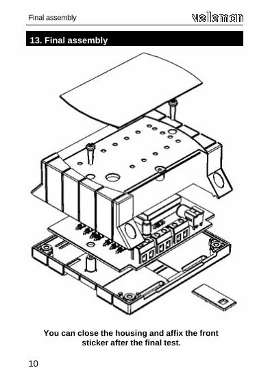
13. Final assembly
Final assembly
You can close the housing and affix the front sticker after the final test.
11
Test
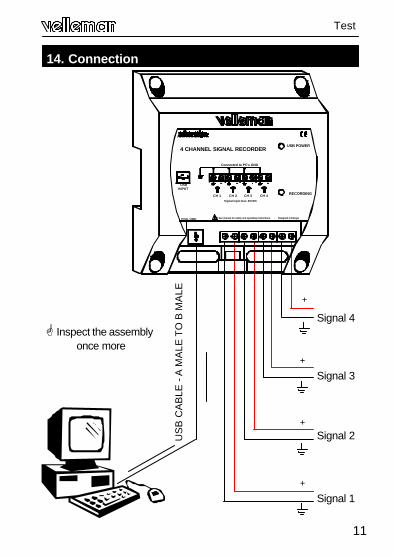
14. Connection
Signal 4
+
US
B C
AB
LE -
A M
ALE
TO
B M
ALE
INSTRUMENTS
PCS10 / K8047
USB INPUT
* See manual for safety and operating instructions. - Designed in Europe
RECORDING
4 CHANNEL SIGNAL RECORDERUSB POWER
CH 1 CH 2 CH 3 CH 4Signal input max. 30VDC
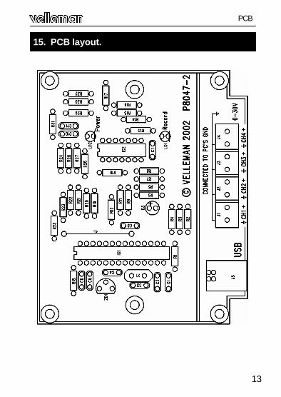
Connected to PC's GND
®
Signal 3 +
Signal 1 +
Signal 2 +
G Inspect the assembly once more

12
PCB &
DIAGRAM
13
15. PCB layout.
PCB
14
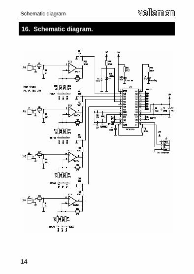
16. Schematic diagram.
Schematic diagram

15
Notes :

16
Modifications and typographical errors reserved © Velleman Components nv. H8047IP - 2003 - ED1
Top Related