


Languages
Pages
Legal


SMS Guide
dn98905102Issue 5-0 en
# Nokia CorporationNokia Proprietary and Confidential
1 (267)
MSCDOCM13M13.0 Product Documentation
The information in this documentation is subject to change without notice and describes only theproduct defined in the introduction of this documentation. This documentation is intended for theuse of Nokia's customers only for the purposes of the agreement under which the documentationis submitted, and no part of it may be reproduced or transmitted in any form or means without theprior written permission of Nokia. The documentation has been prepared to be used byprofessional and properly trained personnel, and the customer assumes full responsibility whenusing it. Nokia welcomes customer comments as part of the process of continuous developmentand improvement of the documentation.
The information or statements given in this documentation concerning the suitability, capacity, orperformance of the mentioned hardware or software products cannot be considered binding butshall be defined in the agreement made between Nokia and the customer. However, Nokia hasmade all reasonable efforts to ensure that the instructions contained in the documentation areadequate and free of material errors and omissions. Nokia will, if necessary, explain issueswhich may not be covered by the documentation.
Nokia's liability for any errors in the documentation is limited to the documentary correction oferrors. NOKIA WILL NOT BE RESPONSIBLE IN ANY EVENT FOR ERRORS IN THISDOCUMENTATION OR FOR ANY DAMAGES, INCIDENTAL OR CONSEQUENTIAL(INCLUDING MONETARY LOSSES), that might arise from the use of this documentation or theinformation in it.
This documentation and the product it describes are considered protected by copyrightaccording to the applicable laws.
NOKIA logo is a registered trademark of Nokia Corporation.
Other product names mentioned in this documentation may be trademarks of their respectivecompanies, and they are mentioned for identification purposes only.
Copyright © Nokia Corporation 2005. All rights reserved.
2 (267) # Nokia CorporationNokia Proprietary and Confidential
dn98905102Issue 5-0 en
SMS Guide

Contents
Contents 3
List of tables 6
List of figures 7
Summary of changes 11
1 Short Message Services 151.1 Short Message Services Overview 171.2 SMS information elements 181.3 Mobile-originating short message 211.3.1 MO-SM procedure 221.3.2 Unsuccessful MO-SM delivery 241.4 Mobile-terminating short message 241.4.1 MT-SMS procedure 251.4.2 Unsuccessful MT-SM delivery 271.4.3 More-messages-to-send 301.4.4 Command SM and MO-SM with Status Report request 301.5 SMSC Alert 341.6 SMS load sharing 361.6.1 SMRSE over X.25 361.6.2 SMRSE over TCP/IP 381.7 Barring SMS in the MSC 411.8 Welcome SM to the roamer 461.9 Real Time triggering 471.10 Incoming Call Treatment 501.11 Missed Calls Log Service 511.12 Short Message Service on GPRS 521.12.1 SMS over GPRS with MAP version 2 531.12.2 SMS over GPRS with MAP version 3 541.12.3 Comparative example of SMS over GPRS with MAP version 2 and MAP
version 3 591.12.4 GPRS with SMSC-MSC connection through MAP interface 621.13 IN Short Message functionality 631.14 CAMEL short message service 651.14.1 Control of MO-SM with CAMEL 661.14.2 Control of MT-SM with CAMEL 711.14.3 Interworking between CAMEL SM and IN SM 751.15 Short message routing 761.15.1 SMS routing enhancements 801.15.2 Short message routing based on subscriber type 811.16 Sending SMS without SMSC 821.17 SMS Forwarding 871.17.1 Basic forwarded MT-SMS 871.17.2 Provisioning and activating SMS forwarding 891.17.3 MMI procedures to activate SMS forwarding 891.18 Same CLI for multiple subscribers 89
dn98905102Issue 5-0 en
# Nokia CorporationNokia Proprietary and Confidential
3 (267)
Contents
1.19 Sequential alerting and parallel alerting for MultiSIM Service 901.19.1 Delivery of mobile-terminating short messages 911.19.2 MT-SMS routing to the primary member 911.20 Short message charging 911.20.1 SMS charging for subscribers 951.20.2 Charging of SMs generated by applications 971.20.3 Charging of SMs to service applications 981.20.4 Charging of CAMEL SMs 991.20.5 MO-SM fraud prevention 1001.20.6 Mobile number portability solutions for MO-SM charging 1001.21 SMS-related statistics 1011.21.1 SMS statistics in the MSC 1021.21.2 SMS statistics in the HLR 1071.22 Network elements involved in SMS 1081.22.1 SME 1091.22.2 SMSC 1091.22.3 VMSC and VLR 1101.22.3.1 VMSC and VLR in MO-SM procedure 1101.22.3.2 VMSC and VLR in MT-SM procedure 1131.22.4 SMS-IWMSC 1171.22.5 SMS-GMSC 1171.22.6 HLR 1181.22.7 Traffica 1201.23 Interfaces between SMS network elements 1211.23.1 A interface in SMS 1221.23.2 SMRSE in SMS 1221.23.3 MAP in SMS 1251.24 Subscriber interface of SMS 128
2 Configuring network elements for SMS 1312.1 Configuring MAP interface for SMS 1322.1.1 Creating global title analysis 1332.2 Configuring X.25 interface for SMS 1382.2.1 Connecting the SMSC to the SMS-GMSC/SMS-IWMSC 1382.2.2 Creating analysis on SMS application level in the MSC 1482.2.3 Setting parameters so that GSM phase 2+ and MT-SM are supported 1512.3 Configuring TCP/IP connection for SMS 1532.3.1 Connecting the SMSC to the SMS-GMSC/SMS-IWMSC 1532.3.2 Creating analysis on SMS application level in the MSC 1552.3.3 Setting parameters so that GSM phase 2+ and MT-SM are supported 1562.4 Handling SMS-related MAP operations in MSC and HLR 1582.4.1 Handling Error counters in SMS 1602.5 Handling the Welcome SM related parameters 161
3 Managing SMS subscriber-specific data 165
4 Managing SMS network element-specific data 1714.1 Handling User Data in SMS 1714.2 Handling of MNRR in SMS 1724.3 Activating selective CDR generation in SMS 1734.4 Activating Picture message information in the CDR 175
4 (267) # Nokia CorporationNokia Proprietary and Confidential
dn98905102Issue 5-0 en
SMS Guide

4.5 Preventing SMS 1754.5.1 Preventing MT-SMS 1764.5.2 Preventing MO-SM 1774.6 Activating SMS measurement 1794.7 Activating routing enhancement in SMS 181
5 Activating Nokia-specific SMS features 1835.1 PNP numbering for SMS (MO) 1835.2 Handling of IN SMS 1855.3 Activating Real Time triggering 1865.4 Activating MT-SM for Camel Phase 4 1895.5 Activating Direct SM delivery 1895.6 Activating B-IMSI retrieval in MO-side for MNP 190
6 Working examples for SMS management 1916.1 Configuring network elements for short message services with load
sharing 1916.2 Configuring network elements for short message services with more
MSCs connected to the same SMSC 2006.3 Configuring network elements for SMS with load sharing of SMSC clusters
when the traffic category is normal traffic 208
7 Short Message Service Troubleshooting 2297.1 Problems related to SMS network elements 2297.2 Problems related to SMS A interface 2307.3 SMS problems related to SMRSE interface 2327.4 Problems related to SMS charging 236
8 Additional information on SMS 2398.1 MT operation in VMSC 2398.2 SMS procedures performed by MAP 2458.3 Comparison of the SMS functionalities in case of SMRSE over X.25 or
TCP/IP and SS7 MAP SMSC 2518.3.1 Functional differences between SMRSE over X.25 or TCP/IP and SS7
MAP SMSC 2538.4 Functions of SMSC level in SMS 2568.5 Alarms and their meanings in Short Message Service 2578.6 SMS-related general parameter file (PRFILE/FIFILE) parameters 2608.7 Parameters needed for CAMEL SM 2648.8 Parameters for SMS A-interface configuration 2658.9 Parameters needed for Sending SMS without SMSC 2668.9.1 FIFILE parameter 2668.9.2 PRFILE parameters 266
dn98905102Issue 5-0 en
# Nokia CorporationNokia Proprietary and Confidential
5 (267)
Contents

List of tables
Table 1. Short Message Services overview 17
Table 2. MNRR reason codes 28
Table 3. Distribution of number range in available SMSCs 37
Table 4. Error codes in MT-SMS barring 44
Table 5. Events, criteria and types of control 48
Table 6. DPs used for the MO SMS State Model 67
Table 7. DPs used for the MT-SMS state model 73
Table 8. Example of a routing table 78
Table 9. Types of CDR and network elements 95
Table 10. Clear codes involved in SMS measurement counter update 104
Table 11. Explanation of bytes in UTPFIL records 199
6 (267) # Nokia CorporationNokia Proprietary and Confidential
dn98905102Issue 5-0 en
SMS Guide

List of figures
Figure 1. Basic Short Message Service procedure 15
Figure 2. Key characteristics of Short Message Service 16
Figure 3. MO-SM successful case 21
Figure 4. MO-Forward SMS procedure 23
Figure 5. MT-SM successful case 25
Figure 6. MT-Forward-SMS procedure 26
Figure 7. SMS command and status report 31
Figure 8. Successful MO-SM transfer with SMSC-GT-1 parameter 33
Figure 9. Successful MT-SM transfer with the SMSC-GT-1 parameter 34
Figure 10. SMSC alerting 35
Figure 11. SMS load sharing 37
Figure 12. The use of MO-SMS Limiter in load sharing 40
Figure 13. MO-SMS barring configured to the VMSC, case 1 42
Figure 14. MO-SMS barring configured to the VMSC, case 2 43
Figure 15. MO-SMS barring configured to the IWMSC, case 1 43
Figure 16. MO-SMS barring configured to the IWMSC, case 2 44
Figure 17. MT-SMS barring, Case 1 45
Figure 18. MT-SMS barring, Case 2 46
Figure 19. Operation of Real Time triggering 48
Figure 20. Overview of involved network elements 53
Figure 21. Mobile-terminating short message delivery, MS detached for GPRS 55
Figure 22. Sending SMs over GPRS 60
Figure 23. SMS over MAP interface 62
Figure 24. Functional architecture for the support of CAMEL control of MSC-switchedMO SMS 66
Figure 25. MO SMS state model 67
Figure 26. CAMEL mobile-originating short message 68
Figure 27. CAMEL mobile-originating short message with notification of successfulsubmission to gsmSCF 70
dn98905102Issue 5-0 en
# Nokia CorporationNokia Proprietary and Confidential
7 (267)
List of figures

Figure 28. Functional architecture for the support of CAMEL control of MSC-switchedMT SMS 72
Figure 29. MT SMS state model 73
Figure 30. CAMEL mobile-terminating short message 74
Figure 31. SMS routing 77
Figure 32. SMSC address used in MT-SMS between different network elements 79
Figure 33. Short message routing based on prepaid and post-paid subscribers 81
Figure 34. Successful SM delivery 85
Figure 35. Unsuccessful SM delivery, no paging response 86
Figure 36. Unsuccessful SM delivery, absent subscriber 86
Figure 37. Basic forwarded MT-SMS functionality 87
Figure 38. Charging of SMs generated by applications 98
Figure 39. MO-SMS request 111
Figure 40. MO-SMS successful case (positive response) 112
Figure 41. MO-SMS unsuccessful case (negative response) 113
Figure 42. MT-SMS request 114
Figure 43. MT-SMS successful case (positive response) 115
Figure 44. MT-SMS unsuccessful case (negative response) 115
Figure 45. Network elements involved in SMS 121
Figure 46. OSI protocol stack 123
Figure 47. Protocol stack for SMS with TCP/IP 125
Figure 48. OSI compared to ITU-T No. 7 126
Figure 49. MAP-Gd interface in the SMS GSM Phase 2+ network architecture 128
Figure 50. An example for hexadecimal numbers used in alphanumericaddressing 129
Figure 51. An example for alphanumeric addressing from the MS 130
Figure 52. MO-SM interfaces 131
Figure 53. MT-SM interfaces 132
Figure 54. GT analyses in the SMS-GMSC, the result is the HLR 134
Figure 55. GTanalyses in the SMS-GMSC/SMS-IWMSC, the result is the VMSC 134
8 (267) # Nokia CorporationNokia Proprietary and Confidential
dn98905102Issue 5-0 en
SMS Guide
Figure 56. GT analyses in the VMSC, the result is SMS-IWMSC 135
Figure 57. GT analyses in the SMS-IWMSC, the result is the SMS-IWMSC 135
Figure 58. GT analyses in the SMS-GMSC, the result is the SMS-GMSC 136
Figure 59. GT analyses in the HLR, the result is the HLR 137
Figure 60. GT analyses in the VMSC, the result is the VMSC 138
Figure 61. An example of outputting a subscriber's SMS data 167
Figure 62. Real-life configuration with load sharing 192
Figure 63. Real-life configuration with load sharing and more MSCs connected to thesame SMSC 201
Figure 64. Real life configuration with load sharing of SMSC clusters 209
Figure 65. MT-SM in the MCS, channel handover, no SM resending 240
Figure 66. MT-SM in the MSC, channel handover, SM resending takes place 241
Figure 67. MT-SM in the MSC, channel handover, SM resending takes place 242
Figure 68. MT-SM in the MSC, T1 expires, SM resending takes place 243
Figure 69. MT-SMS and MO-SMS procedures performed by MAP 245
Figure 70. MT-SM sending fails, HLR is notified 249
Figure 71. ReadyForSM and Alert-SC procedures 251
Figure 72. SMS architecture in case of SMRSE over X.25 or TCP/IP 252
Figure 73. SMS architecture in case of SS7 MAP 253
Figure 74. Successful MT-SM transfer with two new parameters towards theSMSC 257
dn98905102Issue 5-0 en
# Nokia CorporationNokia Proprietary and Confidential
9 (267)
List of figures

10 (267) # Nokia CorporationNokia Proprietary and Confidential
dn98905102Issue 5-0 en
SMS Guide
Summary of changes
Summary of changes
Changes between document issues are cumulative. Therefore, the latest documentissue contains all changes made to previous issues.
Changes made between issues 5�0 and 4�5
Changes due to feature MT-SM for CAMEL Phase 4 :
. Subsection Control of MT-SM with CAMEL has been added to SectionCAMEL short message service .
Information on IN MT functionality has been added to SubsectionInterworking between CAMEL SM and IN SM .
. Subsection Activating MT-SM for Camel Phase 4 has been added toSection Activating Nokia-specific SMS features .
. Parameter CAMEL_ACTIVE has been added to Section Parametersneeded for CAMEL SM .
. Information related to this feature has been added to parameterCAMEL_SUPPORTED_PHASE in Section Parameters needed forCAMEL SM .
Changes made between issues 4�5 and 4�4
Changes due to feature Terminal Management Support :
. Information on the additional functionality of Terminal ManagementSupport has been added to Subsection Real Time triggering .
. NVLAI parameter has been added to Subsection Real Time triggering .
. Information on the activation and deactivation of the feature has beenadded to Subsection Real Time triggering .
. Information on activating Common MSISDN Sending has been added toSubsection Activating Real Time Triggering .
Changes due to feature SMS Routing Based on Subscriber Type :
. Subsection Short message routing based on subscriber type has beenadded to Section Short Message Routing .
Changes due to feature Supplementary Services Phase 2 Extensions :
dn98905102Issue 5-0 en
# Nokia CorporationNokia Proprietary and Confidential
11 (267)
Summary of changes

. Section SMS Forwarding has been added to Chapter Short MessageServices .
. Parameter SMS_FORW_IN_HLR has been added to Subsection SMS-related general parameter file (PRFILE/FIFILE) parameters .
. Information on new SMS CFU counters has been added to SubsectionSMS-related statistics .
Changes due to feature Sequential and Parallel Alerting for MultiSIM Service :
. Section Sequential and Parallel Alerting has been added to Chapter ShortMessage Services .
Changes due to feature Same CLI for Multiple Subscribers :
. Section Same CLI for Multiple Subscribers has been added to ChapterShort Message Services .
Changes due to feature Missed Calls Log Service :
. Section Missed Calls Log Service has been added to Chapter ShortMessage Services .
Changes due to feature Incoming Call Treatment :
. Section Incoming Call Treatement has been added to Chapter ShortMessage Services .
Changes due to feature B-IMSI Retrieval in MO side for MNP :
. Subsection Mobile number portability solutions for MO-SM charging hasbeen added to Section Short Message Charging .
. Subsection Activating B-IMSI retrieval in MO-side for MNP has beenadded to Section Activating Nokia-specific SMS features .
. Parameter B_IMSI_FOR_MO_SM has been added to Subsection SMS-related general parameter file (PRFILE/FIFILE) parameters .
Changes due to feature Direct SM Delivery :
. Section Sending SMS without SMSC has been added to Chapter ShortMessage Services .
. Subsection Activating Direct SM delivery has been added to SectionActivating Nokia-specific SMS features .
12 (267) # Nokia CorporationNokia Proprietary and Confidential
dn98905102Issue 5-0 en
SMS Guide
. Subsection Parameters needed for Sending SMS without SMSC has beenadded to Section Additional information on SMS .
. Information on SMS measurement related to SMs sent without the SMSChas been added to Section SMS-related statistics .
Other changes
. The title VMSC and VLR in SMS has been changed to VMSC and VLRin Chapter Short Message Services .
. The title HLR in SMS has been changed to HLR in Chapter ShortMessage Services .
. The title Traffica in SMS has been changed to Traffica in Chapter ShortMessage Services .
Changes made between issues 4�4 and 4�3
No content changes.
Changes made between issues 4�3 and 4�1
No content changes.
dn98905102Issue 5-0 en
# Nokia CorporationNokia Proprietary and Confidential
13 (267)
Summary of changes

14 (267) # Nokia CorporationNokia Proprietary and Confidential
dn98905102Issue 5-0 en
SMS Guide

1 Short Message Services
The Point-to-Point Short Message Service (SMS-PP) is a basic teleservice usedfor transferring Short Messages (SMs) between a Short Message Entity (SME )and a GSM Mobile Station (MS ). A short message is a freely phrased textmessage with the maximum length of 140 octets. This means 160 characters if aseven-bit coding method is used, but if some other coding method is used, thenumber of characters is less. For more information, see 3GPP TS 23.038.
SMS is very popular since a message can be sent to other subscribers at any time,even when the MS is not reachable.
Figure 1. Basic Short Message Service procedure
There are two different and independent point-to-point services depending on thedirection of the SM transfer:
. Mobile-originating Short Message (MO-SM)
sent by subscriber A and transported from an MS to an SMSC
. Mobile-terminating Short Message (MT-SM)
transported from an SMSC to an MS and received by subscriber B. Thismessage can be input to the SMSC by other mobile users (through an MO-SM) or by a variety of other sources, for example, speech, e-mail, telex, orfacsimile.
SMSC
GSM/PLMNnetwork MT-SM
SME application MO-SM
dn98905102Issue 5-0 en
# Nokia CorporationNokia Proprietary and Confidential
15 (267)
Short Message Services
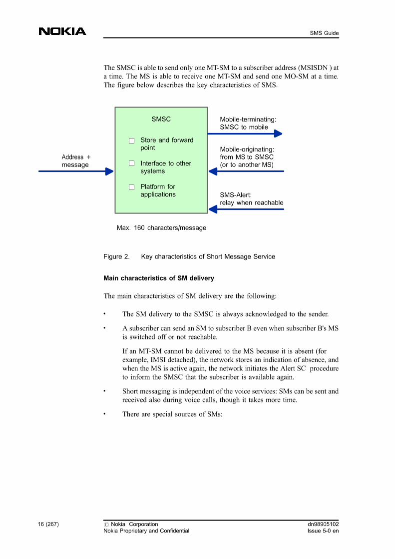
The SMSC is able to send only one MT-SM to a subscriber address (MSISDN ) ata time. The MS is able to receive one MT-SM and send one MO-SM at a time.The figure below describes the key characteristics of SMS.
Figure 2. Key characteristics of Short Message Service
Main characteristics of SM delivery
The main characteristics of SM delivery are the following:
. The SM delivery to the SMSC is always acknowledged to the sender.
. A subscriber can send an SM to subscriber B even when subscriber B's MSis switched off or not reachable.
If an MT-SM cannot be delivered to the MS because it is absent (forexample, IMSI detached), the network stores an indication of absence, andwhen the MS is active again, the network initiates the Alert SC procedureto inform the SMSC that the subscriber is available again.
. Short messaging is independent of the voice services: SMs can be sent andreceived also during voice calls, though it takes more time.
. There are special sources of SMs:
Address +message
Max. 160 characters/message
Mobile-terminating:SMSC to mobile
Mobile-originating:from MS to SMSC(or to another MS)
SMS-Alert:relay when reachable
SMSC
Store and forwardpoint
Interface to othersystems
Platform forapplications
16 (267) # Nokia CorporationNokia Proprietary and Confidential
dn98905102Issue 5-0 en
SMS Guide

- Voice Mail System (VMS ), which can send voice mail alerts to asubscriber to indicate that voice messages were left in the voicemailbox. In some cases the SMSC can also tell the VMS that thesubscriber's MS has become reachable in the GSM network; thus theVMS can make a delivery call to the subscriber.
- various kinds of terminals connected to the SMSC
Note
The topics included in the following sections cover all SMS matters and containthe following features. There are no separate feature activation instructionsavailable for the following features in the current release:
. 327: Short Message Services
. 412: SMS-SMSC Interface, GMSC/IWMSC
. 476: PNP Numbering for SMS (MO)
. 619: Short Message Service Enhancements
. 620: Short Message Services, GSM Phase 2 Enhancements
. 714: Short Message Service Enhancements
1.1 Short Message Services Overview
The following topics are covered under Short Message Services:
Table 1. Short Message Services overview
Short Message Services descriptions andreferential material
Short Message Services Instructions
Short Message Services
Additional information on SMS
Configuring network elements for SMS
Managing SMS subscriber-specific data
Managing SMS network element-specific data
Activating Nokia-specific SMS features
Working examples for SMS management
Short Message Service troubleshooting
dn98905102Issue 5-0 en
# Nokia CorporationNokia Proprietary and Confidential
17 (267)
Short Message Services
1.2 SMS information elements
SMS-related information elements, such as validity period, service centre timestamp, PID, MoreMessagesToSend, priority request, queueing, andMessagesWaiting, are used for sending and receiving SMs. These parametersgive information about the Short Message (SM). The contents and the transfermechanisms have been specified in 3GPP TS 23.040.
The main parameters are explained in the following.
Validity-Period
It indicates how long the SM is valid, that is, if the SM cannot be delivered tosubscriber B immediately, the length of time the SMSC stores the SM beforediscarding it if all delivery attempts fail. Each SM has a validity period, afterwhich SMs that have not been delivered are deleted.
As the originator of an SM submits the SM for delivery, they decide for how longthe delivery attempts should be made if the SM cannot be delivered immediately.Delivery attempts are made until the delivery succeeds, or until the validityperiod expires; in the latter case, the SM is deleted.
The method of giving the validity period depends on the capabilities of themobile phone used, or on the application that sends the message. For detailsregarding each type of mobile phone, refer to their respective instructions anduser guides.
If no validity period is given by the originator, the SMSC inserts a default validityperiod. There is also a maximum validity period system parameter to inhibit theuse of excessive validity period values. This control parameter is an internal MO-SM functionality.
Service-Centre-Time-Stamp
The SMSC uses it to inform the MS about the time when the SM arrived in theSMSC. The time value is included in every SMS-DELIVER message (TP-Service-Centre-Time-Stamp field) delivered to the MS. This control parameter isan internal MT-SMS functionality.
Protocol-Identifier (PID)
The Short Message Transfer Layer (SM-TL) uses it either to refer to a higherlayer protocol, or to indicate interworking with a certain type of device. The SMcan be converted, for example, into SMTP , X.400 mail transfer protocols, or fax.The subscriber chooses the method of sending the SM, and normally it is aregular mobile-to-mobile message. This control parameter is an internal SMSfunctionality.
18 (267) # Nokia CorporationNokia Proprietary and Confidential
dn98905102Issue 5-0 en
SMS Guide
More-Messages-to-Send (MMS)
The SMSC uses this functionality to inform the network in a Mobile-terminatingShort Message (MT-SM) that the SMSC has more messages to send to the samesubscriber. The next short message is not sent until an acknowledgement for theprevious one is received. The connection path between the SMSC and the MS isnot closed until all SMs have been delivered to the MS.
SMS queuing
Queueing takes place when more SMSCs are sending short messages to the samesubscriber at the same time. In this case all incoming SMs are placed in a queuein the VMSC and they are served according to the First-In-First-Out (FIFO)principle.
Information-Element
This field contains information set by the application in the SMS-SUBMIT/DELIVERY, with which the receiving entity is able to re-assemble theconcatenated short messages in the correct order. The field includes the followingelements:
. Concatenated short message reference number : this reference numberremains constant for every SM which makes up a particular concatenatedshort message.
. Maximum number of short messages in the concatenated short message : itindicates the total number of SMs within the concatenated short message.The value remains constant for every SM which makes up theconcatenated short message. If the value is zero, then the receiving entityignores the whole Information Element.
. Sequence number of the current short message : this value starts at 1 andincrements by one for every SM sent within the concatenated shortmessage.
Priority Request
This parameter tells the PLMN whether an SM is a priority message or not. If theSM is not a priority message, and the MS has been identified as temporarilyabsent, the system does not try to deliver it. However, the system tries to deliverthe non-priority SM if the MS has not been identified as temporarily absent, alsowhen it has been identified as having no free memory capacity.
The system tries to deliver a priority SM even if the MS has been identified astemporarily absent or having no free memory capacity.
dn98905102Issue 5-0 en
# Nokia CorporationNokia Proprietary and Confidential
19 (267)
Short Message Services
Messages Waiting (MW)
This service element makes the PLMN store information (Messages WaitingIndication (MWI)) listing the SMSCs that have made unsuccessful short messagedelivery attempts to the MSs in the PLMN in question. The MWI contains thefollowing elements:
. Messages Waiting Data (MWD ) including the address list of the SMSCshaving messages waiting to be delivered to the MS
. Mobile Station Not Reachable Flag (MNRF) indicating if the address listof the MWD contains one or more entries as a result of an unsuccessful SMdelivery attempt (stored in the VLR and HLR)
. Mobile Station Not Reachable Flag for GPRS (MNRG) indicating if theaddress list of the MWD contains one or more entries as a result of anunsuccessful SM delivery attempt (stored in the SGSN and HLR)
. Mobile Station Not Reachable Reason (MNRR ) for GSM and SGSNstoring the reason why an MS is absent when an attempt to deliver a shortmessage failed in the MSC
. Mobile Station Memory Capacity Exceeded Flag (MCEF) indicating thatthe mobile station memory capacity does not allow short message delivery(stored in the HLR).
For more information on SMS elements, see 3GPP TS 23.040.
Main parameters on the Short Message Relay Protocol (SM-RP) layer
The following parameters are visible on the Short Message Relay Protocol (SM-RP) layer according to 3GPP TS 23.040.
Mobile-terminating short messages:
. SMSC Address
. Destination Address (IMSI or MSISDN of subscriber B)
. User Data containing Short Message Transfer Layer Protocol Data Unit(SM-TL PDU )
. Message Reference
. Priority Request
. More Messages To Send
Mobile-originating short messages:
20 (267) # Nokia CorporationNokia Proprietary and Confidential
dn98905102Issue 5-0 en
SMS Guide
. Message Reference
. Originating Address (subscriber A)
. Destination Address (SMSC)
. User Data containing Short Message Transfer Layer Protocol Data Unit(SM-TL PDU)
1.3 Mobile-originating short message
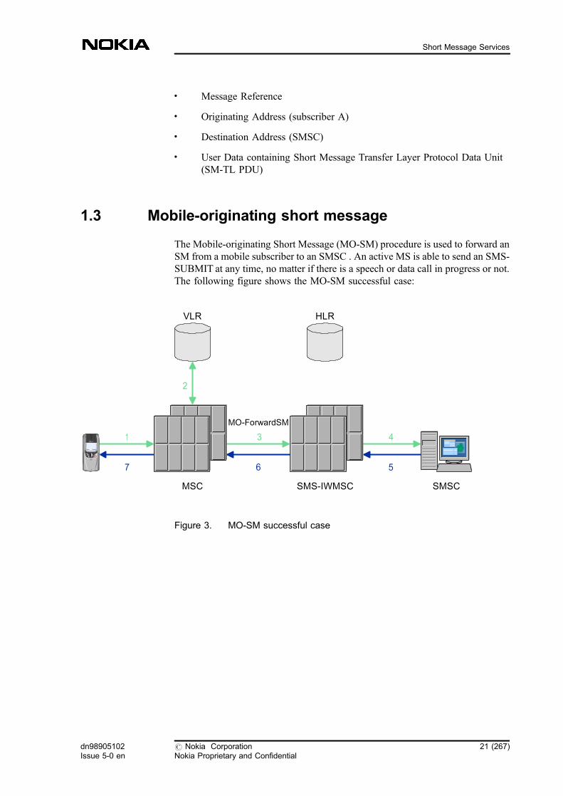
The Mobile-originating Short Message (MO-SM) procedure is used to forward anSM from a mobile subscriber to an SMSC . An active MS is able to send an SMS-SUBMIT at any time, no matter if there is a speech or data call in progress or not.The following figure shows the MO-SM successful case:
Figure 3. MO-SM successful case
SMSCMSC SMS-IWMSC
41
2
HLRVLR
7 6
MO-ForwardSM
5
3
dn98905102Issue 5-0 en
# Nokia CorporationNokia Proprietary and Confidential
21 (267)
Short Message Services
1.3.1 MO-SM procedure
MO-SM procedure when the SMSC is connected through the SMRSEinterface
1. The MS sends an SM to the VMSC through SDCCH (if the MS is idle) orSACCH (if the MS is busy) signalling channel on the radio interface. TheSM includes the address of the SME where the SMSC eventually attemptsto forward the SM.
2. The VMSC checks the data of subscriber A from the VLR.
3. The VMSC routes the SM to the SMS-IWMSC . The result of the GlobalTitle analysis should be the own signalling point code in the IWMSC .
4. The SMS-IWMSC routes the SM to the SMSC. A special OSI or TCP/IPapplication is used between SMS-IWMSC and SMSC, and the SM can besent through this application.
5. The SMSC sends a delivery report to the SMS-IWMSC through the OSI orTCP/IP application.
6. The SMS-IWMSC sends a delivery report to the VMSC.
7. The VMSC sends a report to the MS of subscriber A through SDCCH orSACCH . The report is a delivery or a failure report, depending on whetherthe sending was successful or not. In other words, it either confirms thatthe SMSC has received the SMS-SUBMIT, or informs the MS that it wasimpossible to deliver the SMS-SUBMIT to the SMSC, including thereason why.
22 (267) # Nokia CorporationNokia Proprietary and Confidential
dn98905102Issue 5-0 en
SMS Guide
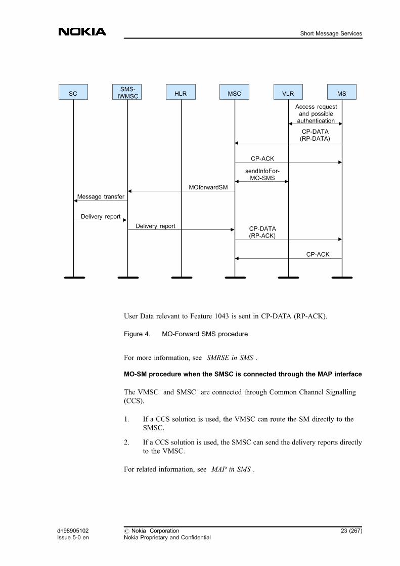
User Data relevant to Feature 1043 is sent in CP-DATA (RP-ACK).
Figure 4. MO-Forward SMS procedure
For more information, see SMRSE in SMS .
MO-SM procedure when the SMSC is connected through the MAP interface
The VMSC and SMSC are connected through Common Channel Signalling(CCS).
1. If a CCS solution is used, the VMSC can route the SM directly to theSMSC.
2. If a CCS solution is used, the SMSC can send the delivery reports directlyto the VMSC.
For related information, see MAP in SMS .
SC
Access requestand possibleauthentication
SMS-IWMSC HLR MSC VLR MS
CP-DATA(RP-DATA)
CP-ACK
sendInfoFor-MO-SMS
MOforwardSM
Message transfer
Delivery report
Delivery report CP-DATA(RP-ACK)
CP-ACK
dn98905102Issue 5-0 en
# Nokia CorporationNokia Proprietary and Confidential
23 (267)
Short Message Services
You can also find related information in Welcome SM to the roamer , andNetwork elements involved in SMS .
1.3.2 Unsuccessful MO-SM delivery
The sending of the MO-SM can fail in any of the below situations:
. Subscriber A does not have the T22 (MO-SMS) subscription(TeleserviceNotProvisioned).
. Operator-determined barring is activated by the network operator orbarring supplementary service is activated by the subscriber.
. SMSC address prevention is defined (UnknownSc on the MAP interface).
. A-number prevention is defined (UnknownSC on the MAP interface).
. The MO-SM facility is not supported in the network (FacilityNotSupportedon the MAP interface).
. The Short Message Service Centre is unknown (UnknownSc on the MAPinterface).
. The short message transfer is rejected because the SME address is invalid(InvalidSME-Addr on the MAP interface).
. Subscriber A is not the subscriber of the relevant SMSC(UnidentifiedSubscriber on the MSC-SMSC interface).
. There is congestion in the SMSC (SC-Congestion on the MSC-SMSCinterface).
. In case of an Intelligent Network (IN ) subscriber, the SCP can bar theshort message submission.
The error code depends on the SCP.
. System failure (SystemFailure on the MAP interface and MSC-SMSCinterface)
1.4 Mobile-terminating short message
The MT-SM procedure is used to transfer an SM sent from the SMSC to a mobilestation. An active MS is able to receive an SMS-DELIVER at any time,independently of whether or not there is a speech or data call in progress. Thefollowing figure shows the successful MT-SM case.
24 (267) # Nokia CorporationNokia Proprietary and Confidential
dn98905102Issue 5-0 en
SMS Guide

Figure 5. MT-SM successful case
1.4.1 MT-SMS procedure
MT-SMS procedure when the SMSC is connected through SMRSE interface
The following figure shows a normal case where the sending of MT-SMsucceeds:
Note that when the priority flag is set, the delivery is attempted even when theMNRF flag is set.
SMS-GMSC MSC
HLR VLR
SMSC
MT-ForwardSM
51
8 6
4SendRoutingInfoForSM 7
3
2
dn98905102Issue 5-0 en
# Nokia CorporationNokia Proprietary and Confidential
25 (267)
Short Message Services

User Data relevant to Feature 1043 is sent in CP-ACK.
Figure 6. MT-Forward-SMS procedure
1. The SMSC sends the SM to the SMS-GMSC by using the SMRSEprotocol.
2. The SMS-GMSC requests the VMSC or SGSN address from the HLR.
3. The SMS-GMSC routes the SM to the VMSC/SGSN.
4. The VMSC asks the VLR for the status and location area of the MS ofsubscriber B . For information on the operations in the SGSN, see Mobile-terminating short message over GPRS .
SC
Message transfer
SMS-GMSC HLR MSC VLR MS
CP-DATA(RP-DATA)
SendInfoFor-MT-SM
Delivery report
SendRoutingInfoForShortMsg
MTforward-ShortMessage
SendInfoFor-MT-SM (Ack/NAck)
Provide LoactionInfo
Provide LoactionInfo Ack/NAck
Page
Authent.
Delivery report
26 (267) # Nokia CorporationNokia Proprietary and Confidential
dn98905102Issue 5-0 en
SMS Guide
5. If the MS is in idle mode, the VMSC starts paging and delivers the SM to itthrough the SDCCH of the BTS where the MS is located. If the MS is inbusy mode, the VMSC sends the SM through the SACCH .
The MS sends a delivery report to the VMSC after receiving the SM.
6. The VMSC sends the delivery report to the SMS-GMSC. In the case ofCCS solution, every MSC must have a GT analysis for routing the SMSC-ISDN address to the SMSC, and the SMSC must have the GT analysis forreceiving that message.
7. The SMS-GMSC sends the delivery report to the HLR if needed.
8. The SMS-GMSC sends the delivery report to the SMSC either confirmingthat the MS has received the SM, or informing the SMSC that it wasimpossible to deliver the SM to the MS, including the reason why.
For more information, see SMRSE in SMS .
MT-SMS procedure when the SMSC is connected through the MAP interface
The SMSC in the MT-SMS procedure has a MAP interface and has the SMS-GMSC function.
1. If a CCS solution is used, the SMSC can request the VLR address fromthe HLR and route the SM directly to the VMSC.
2. If a CCS solution is used, the VMSC can send the delivery reports directlyto the SMSC.
For related information, see MAP in SMS .
Some related information can also be found in Welcome SM to the roamer andNetwork elements involved in SMS .
1.4.2 Unsuccessful MT-SM delivery
The delivery of the MT-SM can fail if any of the following conditions areapplicable:
. Subscriber B is absent (AbsentSubscriber on the MAP interface). As aresult, MWD (including the SMSC address) and the MNRF flag are set inthe HLR. Furthermore, the MNRR stores one of the below detailedreasons for the MS being absent.
Note that these reason codes are not available through X.25. See alsoHandling of MNRR .
dn98905102Issue 5-0 en
# Nokia CorporationNokia Proprietary and Confidential
27 (267)
Short Message Services

Table 2. MNRR reason codes
Reason code Network element setting thereason code
No paging response through the MSC VLR
IMSI detached VLR
Roaming restriction HLR
MS purged for non-GPRS HLR
No paging response through the SGSN SGSN
MS purged for GPRS HLR
Unidentified subscriber through the MSC * SMS-GMSC
Unidentified subscriber through the SGSN * SMS-GMSC
GPRS detached SGSN
* Note that the VMSC or SGSN sends the Unidentified Subscriber error code to the SMS-GMSC and the SMS-GMSC maps it to Absent Subscriber error code.
For detailed information see Short Message Service on GPRS .
. If both Feature 714: Short Message Services Enhancements and Feature1043: Short Message Services GSM Phase 2+ are active, feature 1043overrides feature 714, and the MNRR is sent to the HLR.
. The subscriber is unknown in the VLR (UnidentifiedSubscriber on theMSC-SMSC interface). As a result, (including the SMSC address) theMNRF flag is set in the HLR.
. The subscriber is unknown in the HLR (UnknownSubscriber on the MSC-SMSC interface). In this case, the MWI is not set.
. If the global title analysis fails in the SMS-GMSC towards the HLR, theSMSC receives the Unknown_Subscriber error code from the SMS-GMSC. This error code is a permanent error code, and consequently theSMSC ceases to retry the sending of the SM. This way the useless load ofthe network can be avoided.
. An SMSC is trying to send an SM to the subscriber while another SMSC isalready sending him SMs (the paging request is rejected due toBusySubscriber on the MAP interface).
28 (267) # Nokia CorporationNokia Proprietary and Confidential
dn98905102Issue 5-0 en
SMS Guide
. MNRF flag is set in the HLR, but the priority flag is not set.
The corresponding error code is transferred on the MSC-SMSC interface.
. Information is found in the HLR that incoming call barring applies tosubscriber B (CallBarred on the MSC-SMSC interface).
. A positive response is received for paging, but the memory capacity of theMS is exceeded (the MCEF flag was not set in the HLR), and the MemoryCapacity Exceeded informing procedure starts (MemoryCapacityExceededon the MAP interface). As a result, MWD (including the SMSC address)and the MCEF flag are set in the HLR.
. In case of an Intelligent Network (IN ) subscriber, the SCP can respondwith a ReleaseCall message, which results in the MSC/VLR notforwarding the SM to Subscriber B.
The error code depends on the SCP, and it is transferred on the MAPinterface.
. SMSC address is barred for the visitor subscribers (FacilityNotSupportedon the MAP interface).
. SMSC address is barred for home subscribers (IllegalSubscribers on theMAP interface).
. System failure occurs (SystemFailure on the MAP interface).
Special conditions
. If subscribers are temporarily out of coverage, and a short message is sentto them, an MNRF is set in the VLR. The service centre address is set inthe subscriber's message waiting data (MWD) list. When the MS goes backto coverage area, the VLR does not recognise any change, so the MNRF isnot checked until a call or a periodic location update is made. This situationcauses delay in the SM delivery.
As a Nokia proprietary solution, instead of 'Absent Subscriber' a 'Systemfailure' error code is sent to the SMS-GMSC from the VMSC. The SMS-GMSC maps this 'System failure' to temporary 'Invalid SME address' errorcode towards the SMSC. This error code is not used for any other MT-SMprocedure, so the SMSC can handle it as a temporary error situation andpolls the subscriber periodically because only the MWF is set in the VLR.Note that the solution works only with Nokia SMS-GMSC and VMSC.
If no MT-SM delivery is possible through the MSC, the SGSN route canalso be tried.
dn98905102Issue 5-0 en
# Nokia CorporationNokia Proprietary and Confidential
29 (267)
Short Message Services
. If a mobile station cannot receive short messages because of memoryshortage, a special error code 'memory capacity exceeded' is returned andcarried to the SMS-GMSC through the MAP protocol.
1.4.3 More-messages-to-send
More-messages-to-send (MMS) is an information element offering an MS(receiving a short message from an SMSC) the data whether there are still moremessages waiting to be sent from that SMSC to the MS. The SMS applicationreads the MMSWaitTimer from the PRFILE. In MMS case the second route isnever tried in the SMS-GMSC.
For more information on the PRFILE, see MMS-related parameters in SMS-related general parameter file (PRFILE/FIFILE) parameters .
1.4.4 Command SM and MO-SM with Status Report request
In GSM phase 2, the MS is able to command the SMSC . Subscriber A, forexample, can cancel an SM that has not yet been delivered to subscriber B, or canrequest a status report about whether the SM was delivered to the subscriber ornot. These commands appear as ordinary SMs to the network, but the SM datacontains a field indicating the message type. This message type is extracted fromthe SM for charging and statistical purposes.
The network indicates the result of the command to the subscriber by StatusReport. This message type is extracted from the SM for charging and statisticalpurposes.
MO-SM with Status Report request
When subscribers send mobile-originating SMs, they can request information onwhether the SM was delivered to the destination MS, or not. It is possible if theStatus Report Request field is set in the mobile-originating SM by the sender. Ifthe SM was delivered, or cannot be delivered at all, Status Report is sent to theoriginator of the SM indicating the result of the delivery. The information aboutwhether the Status Report request is set in the MO-SM is carried from the SMSapplication to the charging application, and in this case the SMMO CDR can begenerated with the 'Mobile originated short message status report requested' SMStype value. It means that if the optional PRFILE parameterMO_SM_STATUS_REP_REQ is turned on, you are able to apply differentcharging for MO-SMs in which Status Report is requested.
30 (267) # Nokia CorporationNokia Proprietary and Confidential
dn98905102Issue 5-0 en
SMS Guide

Figure 7. SMS command and status report
For related information, see SMS status report .
The relevant parameter can be found among SMS-related general parameter file(PRFILE/FIFILE) parameters .
SMSC address on the MSC-SMSC interface
The SMSC address used by the MS can be sent to the SMSC on the TCP/IPinterface.
If an SMSC number modification happens in the MSC due to different SMSapplications (such as bank information), the new SMSC address is used forrouting purposes. However, the old SMSC address is also needed in theStatusReport case, because the mobiles can only understand the SMSC addressesstored in them, that is, the ones that were used in SM sending.
The MSC sends the SMSC address given by the subscriber to the SMSC on theTCP/IP interface. It does not affect the MSC-SMSC interface because thisparameter was implemented on the interface already for future use.
With SMSC address sent to the SMSC, you do not need to use predefined SMSCaddresses because the StatusReport is appropriate even if you have several SMSCaddresses.
With the help of this functionality you can also use the networked SMSCsolution: several SMSCs can be connected to the network with a single SMSCnumber, resulting in messages being routed according to destination number tothe nearest SMSC.
Note
SMSCMSC
SMS-Command
SMS-Command:What happened to the SM
I sent to my friend?
SMS-StatusReportSMS-StatusReport:Your SMS was delivered
at 16:51 pm.
1 2
34
dn98905102Issue 5-0 en
# Nokia CorporationNokia Proprietary and Confidential
31 (267)
Short Message Services

You can use this feature if you have the SMSC connected through MAP (in theVMSC function), and also if you have the SMSC connected through SMRSEwith TCP/IP. MAP version 3 is needed for this functionality. For details refer tothe feature activation instructions of Feature 1165: Short Message Services, GSMPhase 2+ Enhancements .
In MO-SMS the SMSC-GT-1 represents the SMSC address given by thesubscriber, and the SMSC-GT-2 represents the SMSC address given by theVMSC. If the SMSC address is changed in the VMSC, then the new SMSCaddress (SMSC-GT-2) is used on the SCCP level for routing purposes, but theMS-defined address is sent in the MO_FORWARD_SMMAP operation. Numbermodification can also take place in the SMS-IWMSC. In this case the numbergiven by the subscriber is sent to the SMSC (SMSC-GT-1), and the new address(SMSC-GT-2) is used only for routing purposes.
32 (267) # Nokia CorporationNokia Proprietary and Confidential
dn98905102Issue 5-0 en
SMS Guide

Figure 8. Successful MO-SM transfer with SMSC-GT-1 parameter
In MT-SMS the SMSC-GT-1 represents the SMSC address given by the MS, andthe SMSC-GT-2 represents the physical SMSC address that is used by thesubscriber.
The transfer of the SMSC address given by the subscriber to the SMSC causeschanges in the VMSC, SMS-IWMSC, and SMS-GMSC .
MS
CP_DATA
VMSCSMS
IWMSC SMSC
CP_ACK
number modification
MAP_MO_FORWARD_SM(SMSC-GT-1)
SMSC-GT-2 on SCCP level for routing
SC_RP_MO_DATA(SMSC-GT-1)
SC_RP_MO_DATA_ACKMAP_MO_FORWARD_SM_ACK
CP_DATA
CP_ACK
dn98905102Issue 5-0 en
# Nokia CorporationNokia Proprietary and Confidential
33 (267)
Short Message Services

Figure 9. Successful MT-SM transfer with the SMSC-GT-1 parameter
1.5 SMSC Alert
The GSM system uses Alert-SC to inform the SMSC (which acts as a store andforward centre for SMs), that a subscriber has become available again and cannow receive new messages. There are two cases in which the system knows whento send the Alert-SC:
SMSCSMS-GMSC HLR VMSC MS
SC_RP_MT_DATA(SMSC-GT-1, SMSC-
GT-2)
MAP_SEND_ROUTING_INFO_FOR_SM (SMSC-
GT-2
MAP_SEND_ROUTING_INFO_FOR_
SM_ACK
MAP_MT_FORWARD_SHORT_MESSAGE
(SMSC-GT-1)
Page
Positive page response
CP_DATA
CP_ACK
CP_DATA
CP_ACKMAP_MT_FORWARD_SHORT_MESSAGE
_ACK
SC_RP_ACK
34 (267) # Nokia CorporationNokia Proprietary and Confidential
dn98905102Issue 5-0 en
SMS Guide
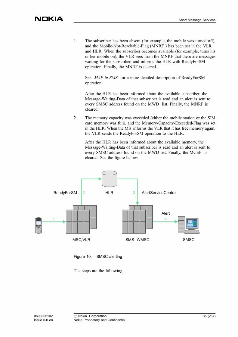
1. The subscriber has been absent (for example, the mobile was turned off),and the Mobile-Not-Reachable-Flag (MNRF ) has been set in the VLRand HLR. When the subscriber becomes available (for example, turns hisor her mobile on), the VLR sees from the MNRF that there are messageswaiting for the subscriber, and informs the HLR with ReadyForSMoperation. Finally, the MNRF is cleared.
See MAP in SMS for a more detailed description of ReadyForSMoperation.
After the HLR has been informed about the available subscriber, theMessage-Waiting-Data of that subscriber is read and an alert is sent toevery SMSC address found on the MWD list. Finally, the MNRF iscleared.
2. The memory capacity was exceeded (either the mobile station or the SIMcard memory was full), and the Memory-Capacity-Exceeded-Flag was setin the HLR. When the MS informs the VLR that it has free memory again,the VLR sends the ReadyForSM operation to the HLR.
After the HLR has been informed about the available memory, theMessage-Waiting-Data of that subscriber is read and an alert is sent toevery SMSC address found on the MWD list. Finally, the MCEF iscleared. See the figure below:
Figure 10. SMSC alerting
The steps are the following:
SMSC
HLR
MSC/VLR SMS-IWMSC
ReadyForSM AlertServiceCentre
Alert
1 4
2 3
dn98905102Issue 5-0 en
# Nokia CorporationNokia Proprietary and Confidential
35 (267)
Short Message Services
1. The MS informs the VLR that it has free memory or has become reachableagain .
2. The VLR informs the HLR with ReadyForSM that the subscriber isavailable or that there is free memory.
3. The HLR searches all SMSC addresses listed in MWD from the subscriberdata and sends an Alert-SC to each of them.
4. The SMS-IWMSC forwards the Alert-SC to the SMSC through OSI orTCP/IP application.
There are two types of repeated delivery attempts from the SMSC (the providersof the SMSC and the network define their application):
1. A repeated delivery attempt because the SMSC has been informed that theMS is active and available for receiving SMs.
2. An automatic repeated delivery attempt performed by the SMSC.
During the Alert-SC procedure there is no load sharing. For further details, seeSMS load sharing . You can also find a list of SMS information elements . Forfurther details, see SMS load sharing . You can also find a list of SMSinformation elements .
1.6 SMS load sharing
1.6.1 SMRSE over X.25
OSI management does not fully support load sharing. It provides load sharingonly when opening a connection. If two or more links exist to an SMSC and theconnections are open, OSI management cannot know how much traffic is goingwithin various connections and suggests the first one to be used so long as it isfunctional. In case of a malfunction, OSI management automatically switches thetraffic onto a functional connection.
Connection parameters are handled in OSI management by defining parametersets and linking them to an Application Entity Name (AEN). When subscriberssend SMs, they use the ISDN number to select an SMSC. In the MSC/VLR, theISDN address is tied to an AEN. By defining several AENs to an ISDN address,several connections can be used for load sharing. The maximum amount of AENconnections is 5.
36 (267) # Nokia CorporationNokia Proprietary and Confidential
dn98905102Issue 5-0 en
SMS Guide
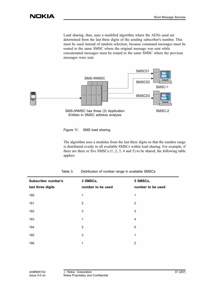
Load sharing, thus, uses a modified algorithm where the AENs used aredetermined from the last three digits of the sending subscriber's number. Thismust be used instead of random selection, because command messages must berouted to the same SMSC where the original message was sent whileconcatenated messages must be routed to the same SMSC where the previousmessages were sent.
Figure 11. SMS load sharing
The algorithm uses a modulus from the last three digits so that the number rangeis distributed evenly to all available SMSCs within load sharing. For example, ifthere are three or five SMSCs (1, 2, 3, 4 and 5) to be shared, the following tableapplies:
Table 3. Distribution of number range in available SMSCs
Subscriber number's
last three digits
3 SMSCs,
number to be used
5 SMSCs,
number to be used
160 1 1
161 2 2
162 3 3
163 1 4
164 2 5
165 3 1
166 1 2
SMSC-2SMS-IWMSC has three (3) ApplicationEntities in SMSC address analysis
SMSC-1
SMS-IWMSC
SMSC01
SMSC02
SMSC03
dn98905102Issue 5-0 en
# Nokia CorporationNokia Proprietary and Confidential
37 (267)
Short Message Services
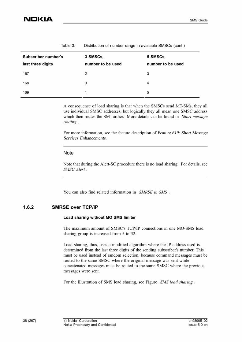
Table 3. Distribution of number range in available SMSCs (cont.)
Subscriber number's
last three digits
3 SMSCs,
number to be used
5 SMSCs,
number to be used
167 2 3
168 3 4
169 1 5
A consequence of load sharing is that when the SMSCs send MT-SMs, they alluse individual SMSC addresses, but logically they all mean one SMSC addresswhich then routes the SM further. More details can be found in Short messagerouting .
For more information, see the feature description of Feature 619: Short MessageServices Enhancements.
Note
Note that during the Alert-SC procedure there is no load sharing. For details, seeSMSC Alert .
You can also find related information in SMRSE in SMS .
1.6.2 SMRSE over TCP/IP
Load sharing without MO SMS limiter
The maximum amount of SMSC's TCP/IP connections in one MO-SMS loadsharing group is increased from 5 to 32.
Load sharing, thus, uses a modified algorithm where the IP address used isdetermined from the last three digits of the sending subscriber's number. Thismust be used instead of random selection, because command messages must berouted to the same SMSC where the original message was sent whileconcatenated messages must be routed to the same SMSC where the previousmessages were sent.
For the illustration of SMS load sharing, see Figure SMS load sharing .
38 (267) # Nokia CorporationNokia Proprietary and Confidential
dn98905102Issue 5-0 en
SMS Guide
The algorithm uses a modulus from the last three digits so that the number rangeis distributed evenly to all available SMSCs within load sharing. For example, ifthere are three or five SMSCs (1, 2, 3, 4 and 5) to be shared, see TableDistribution of number range in available SMSCs
A consequence of load sharing is that when the SMSCs send MT-SMs, they alluse individual SMSC addresses, but logically they all mean one SMSC addresswhich then routes the SM further. More details can be found in Short messagerouting .
TCP/IP protocol also helps in SMRSE capacity problems.
For more information, see the feature descriptions of Feature 931: Short MessageService Transfer over TCP/IP and Feature 619: Short Message ServicesEnhancements .
You can also find related information in SMRSE in SMS .
Load sharing with MO-SMS limiter
Improved load sharing based on the SMSC link capacity value is possible withMO-SMS limiter.
Weighted distribution can be achieved among SMSCs with different capacity, thatis, proportionally equal load can be achieved in all SMSCs if you have Feature1165: Short Message Services GSM Phase 2+ Enhancements in use in yournetwork.
Note
For using this functionality you must have the SMSC connected through SMRSEwith TCP/IP.
If there are SMSCs with different capacity in the network, the proportionallyequal load sharing in the MSC requires the capacity information from the SMSC.
The MO-SMS limiter is sent by the SMSC to the MSC during the connectionestablishment between the MSC and the SMSC. It tells the MSC what the upperlimit for MO-SMs is per second per TCP/IP link. There is an MO-SMS limiter foreach SMSC link. The possible value of this parameter ranges from 0 to 10000MO-SM/sec.
The MSC then controls the number of MO-SMs sent to the SMSC (on one TCP/IP link) per second on the basis of the value of the MO-SMS limiter.
dn98905102Issue 5-0 en
# Nokia CorporationNokia Proprietary and Confidential
39 (267)
Short Message Services
Note, that the AlertSC messages are not counted here.
The value of the MO-SMS limiter for a specific SMSC link is stored in theconnection table of the MSC. The MSC makes the weighted equal distributionamong the links involved in the load sharing based on this value. If a link goesdown, the load sharing is executed among the rest of the SMSC links. Anexception to this is when the error indication is coming from a link because ofoverload situation. In this case the link stays in the load sharing group.
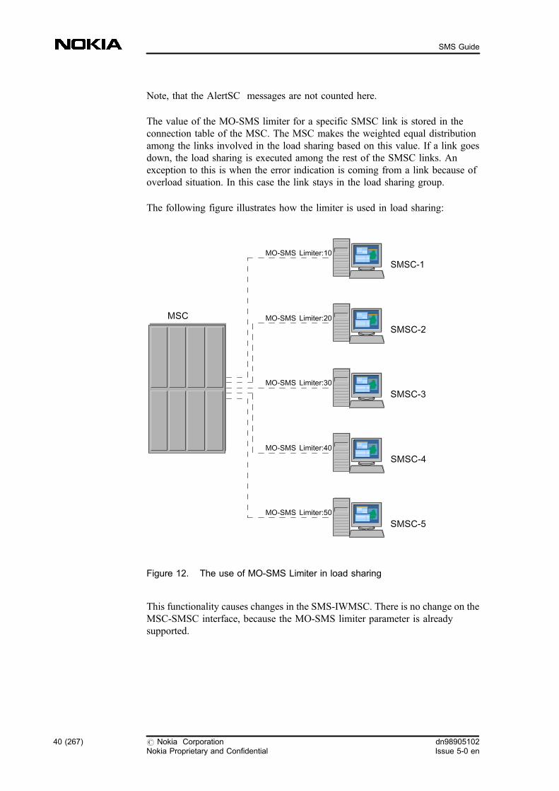
The following figure illustrates how the limiter is used in load sharing:
Figure 12. The use of MO-SMS Limiter in load sharing
This functionality causes changes in the SMS-IWMSC. There is no change on theMSC-SMSC interface, because the MO-SMS limiter parameter is alreadysupported.
MSC
SMSC-1
SMSC-2
SMSC-3
SMSC-4
SMSC-5
MO-SMS Limiter:10
MO-SMS Limiter:20
MO-SMS Limiter:40
MO-SMS Limiter:50
MO-SMS Limiter:30
40 (267) # Nokia CorporationNokia Proprietary and Confidential
dn98905102Issue 5-0 en
SMS Guide
Error situation is raised if you have Feature 1165: Short Message Services, GSMPhase 2+ Enhancements in use but there is no MO Limiter value given for theTCP/IP link. In this case load sharing works in the previously described equaldistribution method, and Alarm 1224, Missing Mo limiter for SMSC link isissued. See also Alarms and their meaning in Short Message Service .
For details, refer to the feature descriptions and feature activation instructions ofFeature 1165: Short Message Services, GSM Phase 2+ Enhancement s.
Further information can also be found in TCP/IP connection .
1.7 Barring SMS in the MSC
Barring of MO-SMS
You can configure certain SMSC and A-subscriber addresses into the VMSC orSMS-IWMSC corresponding to where the MO-SM is not allowed to be sent andfrom whom it is not allowed to be originated, respectively, but only if you haveFeature 1043: Short Message Services GSM Phase 2+ in your network. Withoutfeature 1043 you can only configure MO-deny for all subscribers.
With the help of this feature you can separately define whether the SMSC isbarred for home subscribers, visitor subscribers or for all subscribers.
The MAP interface uses the UnknownSC error code in A-subscriber or SMSCbarring, which results in the UnassignedNumber error code sent from the VMSCto the MS.
If you want to use this functionality, a new SMSC address analysis (MO-DENYanalysis based on SMSC address) is needed to decide whether the use of theSMSC is denied or not. In addition, the A-subscriber MSISDN analysis is alsoadded to the feature.
The following barring cases can be considered in the VMSC:
. When a home subscriber is in the home PLMN, the A-subscriber barring isnot relevant since the removal of the teleservice code from the HLR has thesame effect.
. When a home subscriber is in the home PLMN, the usage of a foreignSMSC can be barred.
. When a foreign subscriber is in the home PLMN, both the A-subscribernumber and the usage of the own SMSC can be barred.
dn98905102Issue 5-0 en
# Nokia CorporationNokia Proprietary and Confidential
41 (267)
Short Message Services
Special conditions
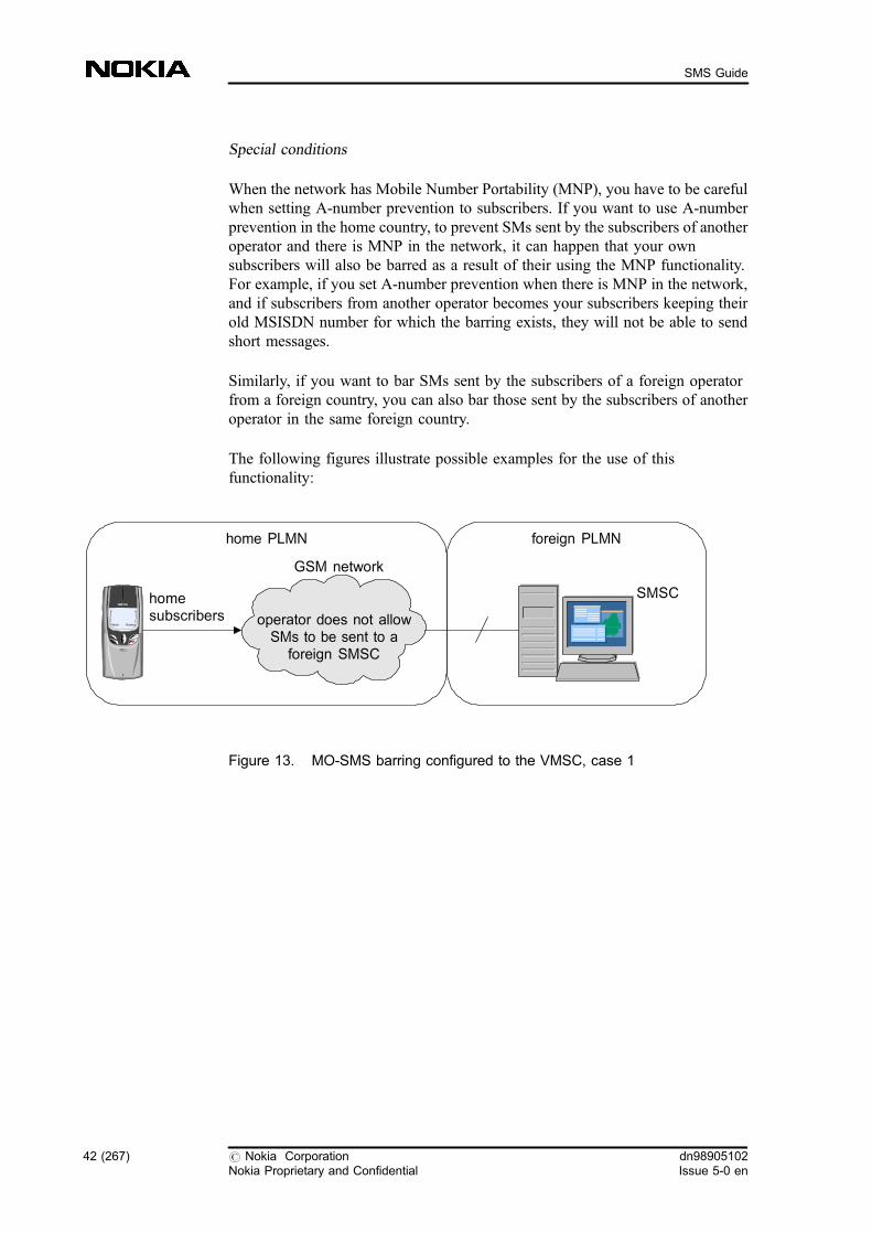
When the network has Mobile Number Portability (MNP), you have to be carefulwhen setting A-number prevention to subscribers. If you want to use A-numberprevention in the home country, to prevent SMs sent by the subscribers of anotheroperator and there is MNP in the network, it can happen that your ownsubscribers will also be barred as a result of their using the MNP functionality.For example, if you set A-number prevention when there is MNP in the network,and if subscribers from another operator becomes your subscribers keeping theirold MSISDN number for which the barring exists, they will not be able to sendshort messages.
Similarly, if you want to bar SMs sent by the subscribers of a foreign operatorfrom a foreign country, you can also bar those sent by the subscribers of anotheroperator in the same foreign country.
The following figures illustrate possible examples for the use of thisfunctionality:
Figure 13. MO-SMS barring configured to the VMSC, case 1
SMSChomesubscribers
foreign PLMNhome PLMN
GSM network
operator does not allowSMs to be sent to a
foreign SMSC
42 (267) # Nokia CorporationNokia Proprietary and Confidential
dn98905102Issue 5-0 en
SMS Guide

Figure 14. MO-SMS barring configured to the VMSC, case 2
The following barring cases can be considered in the SMS-IWMSC:
. When a home subscriber is in the home PLMN the A-subscriber barring isnot relevant since the removal of the teleservice code from the HLR has thesame effect (similarly to the VMSC). In addition, the barring SMSCaddress is not relevant in this case.
. When a foreign subscriber is in the home PLMN, you can bar both the A-subscriber number and the usage of the own SMSC.
. When a foreign subscriber is in the foreign PLMN, you can bar both the A-subscriber number and the usage of the own SMSC. This barring case canonly be configured to the IWMSC.
The following figures illustrate possible examples for the use of thisfunctionality:
Figure 15. MO-SMS barring configured to the IWMSC, case 1
SMSCforeignsubscribers
home PLMN
GSM network
operator does not allowSMs to be sent to his ownSMSC or to be originatedfrom a foreign subscriber
SMSC
home PLMNforeign PLMN
GSM network
foreignsubscribers operator does not allow
SMs to be sent to his ownSMSC or to be originatedfrom a foreign subscriber
dn98905102Issue 5-0 en
# Nokia CorporationNokia Proprietary and Confidential
43 (267)
Short Message Services

Figure 16. MO-SMS barring configured to the IWMSC, case 2
Barring of MT-SMS
You can configure certain SMSC addresses (for example, one located in aforeign country) into the VMSC if you have Feature 1043: Short MessageServices GSM Phase 2+ in your network. This means that no MT-SM is allowedto be originated from that SMSC address.
It is also possible for you to separately define whether a certain SMSC is barred
. for home subscribers
. for visitor subscribers
or
. for all subscribers
When there is barring in the VMSC, it sends an error code to the SMSC.
The following error codes can be sent according to the groups of subscribersconcerned:
Table 4. Error codes in MT-SMS barring
Group ofsubscribersaffected
Error code Type of failure Re-deliveryaccording to theSMSC
Home IllegalSubscriber Permanent No
SMSCforeignsubscribers
home PLMN
GSM network
operator does not allowSMs to be sent to his ownSMSC or to be originatedfrom a foreign subscriber
44 (267) # Nokia CorporationNokia Proprietary and Confidential
dn98905102Issue 5-0 en
SMS Guide

Table 4. Error codes in MT-SMS barring (cont.)
Group ofsubscribersaffected
Error code Type of failure Re-deliveryaccording to theSMSC
Visitor FacilityNotSupported Temporary Yes
All FacilityNotSupported Temporary Yes
Due to the possibility of SMSC barring in MT-SMS case, the filtering needs anSMSC address analysis (MT-DENYanalysis based on the SMSC address) forbarring purpose in the VMSC. The result of the analysis can be barring for allsubscribers, barring for visitor subscribers, barring for home subscribers ornothing (meaning there is no restriction in the VMSC).
This functionality can be useful, for example, if you want to bar the delivery ofshort messages coming from a special SMSC used by an internet service. Forhome subscribers the barring is set as permanent, while for visitor subscribers youset the barring as temporary if you want to enable the subscribers to receive theshort messages after returning to their home network.
To avoid the frequent resending of short messages, you need to set theFacilityNotSupported error code in the SMSC in such a way that the intervalbetween two resendings is as big as possible. This results in a decreased load inthe network.
The following figures illustrate possible examples for the use of thisfunctionality:
Figure 17. MT-SMS barring, Case 1
SMSC
foreignsubscriber
foreign PLMN home PLMN
GSM network
no roaming contractdue to charging problems
dn98905102Issue 5-0 en
# Nokia CorporationNokia Proprietary and Confidential
45 (267)
Short Message Services
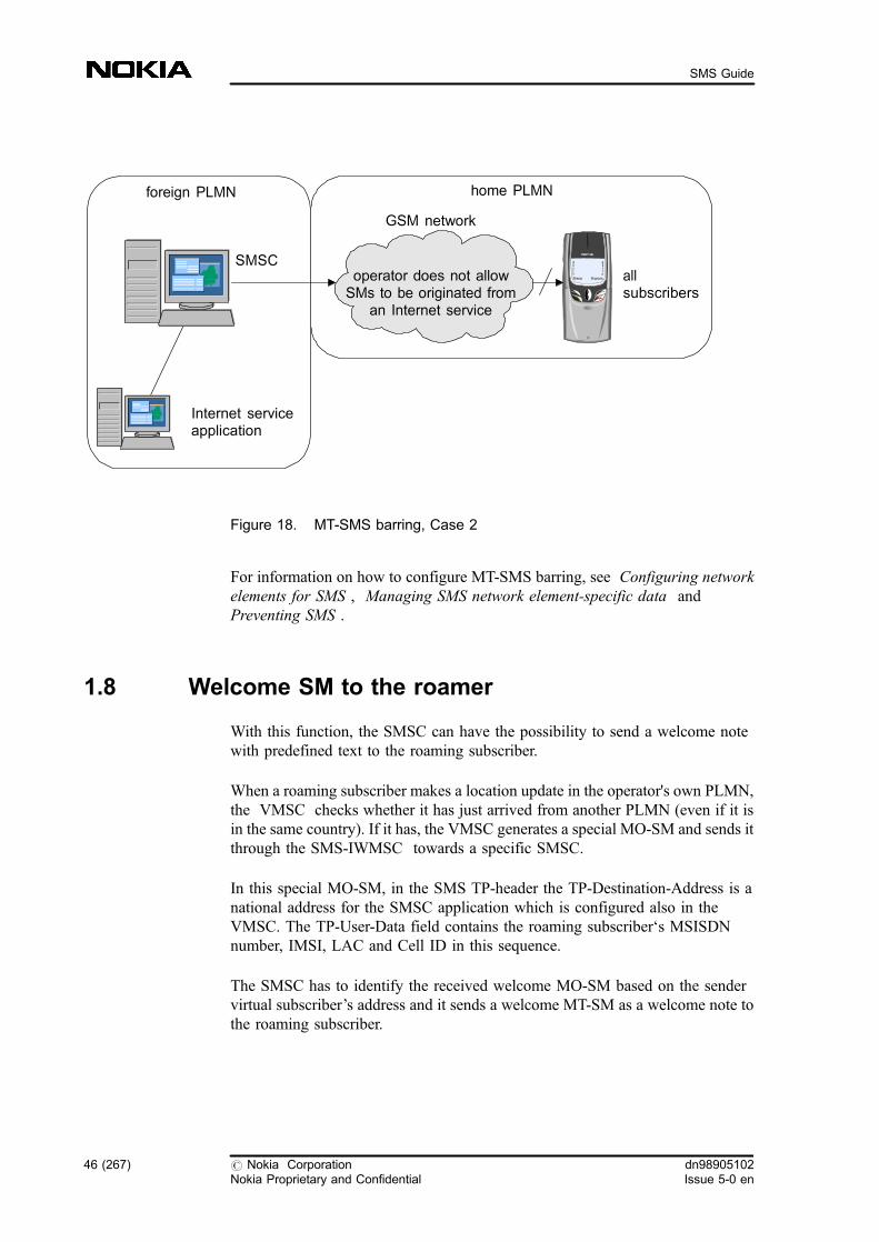
Figure 18. MT-SMS barring, Case 2
For information on how to configure MT-SMS barring, see Configuring networkelements for SMS , Managing SMS network element-specific data andPreventing SMS .
1.8 Welcome SM to the roamer
With this function, the SMSC can have the possibility to send a welcome notewith predefined text to the roaming subscriber.
When a roaming subscriber makes a location update in the operator's own PLMN,the VMSC checks whether it has just arrived from another PLMN (even if it isin the same country). If it has, the VMSC generates a special MO-SM and sends itthrough the SMS-IWMSC towards a specific SMSC.
In this special MO-SM, in the SMS TP-header the TP-Destination-Address is anational address for the SMSC application which is configured also in theVMSC. The TP-User-Data field contains the roaming subscriber�s MSISDNnumber, IMSI, LAC and Cell ID in this sequence.
The SMSC has to identify the received welcome MO-SM based on the sendervirtual subscriber�s address and it sends a welcome MT-SM as a welcome note tothe roaming subscriber.
SMSCallsubscribers
foreign PLMN home PLMN
GSM network
Internet serviceapplication
operator does not allowSMs to be originated from
an Internet service
46 (267) # Nokia CorporationNokia Proprietary and Confidential
dn98905102Issue 5-0 en
SMS Guide
You have to configure the SMSC address and the SMSC application address inthe VMSC for the welcome SM. You also have to define a virtual MSISDNnumber (C-MSISDN) as the originator of the created MO-SM in the VMSC.
Note
In MAP version 2 the virtual subscriber also has to be created in the HLR. It isnot necessary in case of MAP version 3.
The welcome SM functionality is based on a Nokia proprietary solution, whichworks with an SMSC which supports SM routing towards the application.
For activation instructions see Handling the Welcome SM related parameters .
The interface type does not affect the Welcome SM operation. It can be SS7,TCP/IP or X.25 towards the SMSC.
For further details see the feature description of Feature 1043: Short MessageServices, GSM Phase 2+ .
You can also find related information in Mobile-terminating short message .
1.9 Real Time triggering
With Real Time triggering, the MSC/VLR can provide data to the Nokia TerminalManagement Server, and in this way NTMS can configure the mobile phonewithout the manual typing of end user or operator. As soon as the VLR detects anevent, it sends the trigger to NTMS, and these triggers are sent by Short Message,since NTMS has direct connection to the SMSC.
For an overview of the operation of the Real Time triggering, see the followingfigure:
dn98905102Issue 5-0 en
# Nokia CorporationNokia Proprietary and Confidential
47 (267)
Short Message Services

Figure 19. Operation of Real Time triggering
When the VLR receives an access request from the subscriber and the IMEIchecking is switched ON, the VLR gets the subscriber's IMEI number. After thesuccessful location update VLR or IMEI changes in the database (IMEI1 changesto IMEI2) the Real Time triggering functionality can start. Since these triggerSMs result in additional load in the MSC-SMSC interface, you can control whichevent has to be detected.
Table 5. Events, criteria and types of control
Event detection Filtering criteria Control of eventdetection
Defaultactivationstatus
IMEI changes in the VLRdatabase
HOME / VISITOR subscriber
or
MS-CLASSMARK
Can be switched ON/OFF ON
Detected Event
- Inter-PLMN location update- IMEI changes in the database- New visitor with special previous LAC
IMEI checking
MS
VMSC
Trigger SM(MSISDN, IMEI, IMSI,
Detec.event, Common MSISDN)
IWMSC
Forward MO-SM
SMSC
NTMS
CIMDStatistic report: trigger SM
Operator has to set
- SMSC address- SMSC application address- Sender (A number) of the trigger SM- IMEI checking
48 (267) # Nokia CorporationNokia Proprietary and Confidential
dn98905102Issue 5-0 en
SMS Guide

Table 5. Events, criteria and types of control (cont.)
Event detection Filtering criteria Control of eventdetection
Defaultactivationstatus
Inter-PLMN locationupdate of new visitor
HOME / VISITOR subscriber
or
MS-CLASSMARK
Can be switched ON/OFF OFF
New visitor with specialprevious LAC
HOME / VISITOR subscriber
or
MS-CLASSMARK
Can be switched ON/OFF OFF
Based on this table, you can set three kinds of EVENT, and two kinds ofCRITERIA in the VLR parameter file.
. It is possible to differentiate between the types of mobile stations by usingthe MS_CLASSMARK parameter.
. The HOME/VISITOR parameter makes it possible that either the HOMEsubscriber, or the VISITOR subscriber is detected only, or both.
. The Inter-PLMN location update event indicates a subscriber who has justarrived from a foreign country. The national roamers are not detected.
. The New visitor with special previous LAC event can indicate a newsubscription in the network.
With the configurable UTPFIL parameter, it is possible to set a differentkind of initial value for the event 'New visitor with special previous LACvalue'.
Note
If the special previous LAC is zero, it can also mean an unsuccessful locationupdate.
dn98905102Issue 5-0 en
# Nokia CorporationNokia Proprietary and Confidential
49 (267)
Short Message Services
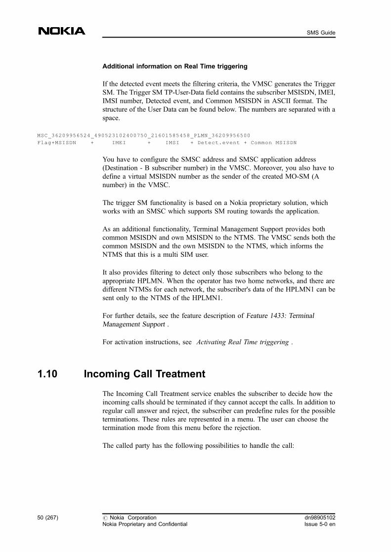
Additional information on Real Time triggering
If the detected event meets the filtering criteria, the VMSC generates the TriggerSM. The Trigger SM TP-User-Data field contains the subscriber MSISDN, IMEI,IMSI number, Detected event, and Common MSISDN in ASCII format. Thestructure of the User Data can be found below. The numbers are separated with aspace.
MSC_36209956524_490523102400750_21601585458_PLMN_36209956500
Flag+MSISDN + IMEI + IMSI + Detect.event + Common MSISDN
You have to configure the SMSC address and SMSC application address(Destination - B subscriber number) in the VMSC. Moreover, you also have todefine a virtual MSISDN number as the sender of the created MO-SM (Anumber) in the VMSC.
The trigger SM functionality is based on a Nokia proprietary solution, whichworks with an SMSC which supports SM routing towards the application.
As an additional functionality, Terminal Management Support provides bothcommon MSISDN and own MSISDN to the NTMS. The VMSC sends both thecommon MSISDN and the own MSISDN to the NTMS, which informs theNTMS that this is a multi SIM user.
It also provides filtering to detect only those subscribers who belong to theappropriate HPLMN. When the operator has two home networks, and there aredifferent NTMSs for each network, the subscriber's data of the HPLMN1 can besent only to the NTMS of the HPLMN1.
For further details, see the feature description of Feature 1433: TerminalManagement Support .
For activation instructions, see Activating Real Time triggering .
1.10 Incoming Call Treatment
The Incoming Call Treatment service enables the subscriber to decide how theincoming calls should be terminated if they cannot accept the calls. In addition toregular call answer and reject, the subscriber can predefine rules for the possibleterminations. These rules are represented in a menu. The user can choose thetermination mode from this menu before the rejection.
The called party has the following possibilities to handle the call:
50 (267) # Nokia CorporationNokia Proprietary and Confidential
dn98905102Issue 5-0 en
SMS Guide
. simply rejecting the call
. forwarding the call to a certain pre-defined number
. forwarding the call to voice mail
. rejecting the call with a pre-defined notification to be sent in SMS to thecaller
- normal SM: it is stored immediately
- flash SM (class 0): it is received to the user's screen.
The called party can personalise the service by defining the forwarding numbersand the text in the short message. It is also possible for the user to define morealternatives for the diverted-to numbers and the texts to be sent. The ICT serviceplays an announcement to the called party until the network receives an answeron how the call should be treated.
The ICT service functions in case of home and outbound roaming.
For more information see the feature description and the feature activationmanual of Feature 1607: Incoming Call Treatment .
1.11 Missed Calls Log Service
This feature provides indication about the missed calls to the served user. Withthe Missed Calls Log (MCL) functionality the subscriber receives informationabout those calls which were unsuccessful before the alerting phase. In thesecases the network generates a special Short Message (SM), which contains thecaller's number, time of the missed call, and the reason why the call wasunsuccessful. The SM is sent to the MS when it is connected to the networkagain.
The following situations are recorded as missed calls:
. The phone is switched off (International Mobile Subscriber Identity (IMSI)detach; with or without Call Forwarding on Not Reachable (CFNRe ).
. Unconditional Call Forwarding (CFU )
. The phone is out of radio coverage.
. The network is busy or there is a congestion.
. Network Determined User Busy (NDUB )
. network failure before the alerting phase
dn98905102Issue 5-0 en
# Nokia CorporationNokia Proprietary and Confidential
51 (267)
Short Message Services
The log contains the following information:
. caller's number (if available)
. time and date of the missed call
. reason why the call was unsuccessful
The mobile station receives the logs in short messages. By default, one SMcontains one log entry (one unsuccessful call attempt). You can, as an option,choose to combine all log entries for one subscriber into as few SMs as possible.
For more information see the feature description and the feature activationmanual of Feature 1606: Missed Calls Log Service .
1.12 Short Message Service on GPRS
General Packet Switched Services (GPRS) provides packet switched modeservice to mobile stations and terminals. This way data can be sent and receivedby the MS at any time without prearranged network resource reservation or callsetup. Short messages can be efficiently delivered over the GPRS radio interfaceas data packets.
A GPRS service can be subscribed just like the GSM service. There can besubscribers (IMSIs) having both circuit switched GSM services and GPRSservices, or subscribers having GPRS services only, or circuit switched servicesonly.
The following figure gives a general overview of the different network elementsand interfaces involved.
Please note, that this architecture is characteristic of those networks only in whichTCP/IP or X.25 interface, and separate SMS-GMSC and SMS-IWMSC exist.
52 (267) # Nokia CorporationNokia Proprietary and Confidential
dn98905102Issue 5-0 en
SMS Guide

Figure 20. Overview of involved network elements
For further details see the feature descriptions of Feature 857: Support of GeneralPacket Radio Services (GPRS) .
1.12.1 SMS over GPRS with MAP version 2
If MAP version 2 is supported in the MAP-C and MAP-Gd interfaces, the MT-SM through the SGSN is already available. This kind of environment does notrequire any special 'SMS over GPRS' support in the SMS-GMSC or the SMS-IWMSC because as a subscription option you chose in the HLR whether the MT-SM is always delivered through an MSC or through an SGSN. Note that in thiskind of implementation the MT-SM is never tried through the other route.
There is a subscriber-specific parameter which indicates whether the MT-SMshould be sent through the MSC/VLR, or through the SGSN. With the help ofthis parameter in MAP version 2, you can predefine the preferred route in theHLR. It means that always that route is tried when delivering SMs, even if thesubscriber is not reachable through that defined route. The result is, naturally,negative acknowledgement to the SMS-GMSC.
External data networks
GGSN
SGSN
BSS
GPRS MS
MAP (C)MAP (Gd)
MAP (Gr, Gf)
SMS-GMSC/SMS-IWMSC
DX 200 HLR/AUC/EIR
HLR AUC EIR
VMSC
dn98905102Issue 5-0 en
# Nokia CorporationNokia Proprietary and Confidential
53 (267)
Short Message Services
Note
The Send-Routing-Info-for-SM response includes a single switch address, and theSMS-GMSC never knows whether the GSM or the GPRS channel is used toroute the SM. This is entirely dependent on the HLR parameter.
For delivering SMs over GPRS, only HLR support is needed.
The details of MT-SM-related HLR activation can be found in the featureactivation instructions of Feature 857: Support of General Packet Radio Services(GPRS ).
You can also find related information in MAP in SMS , SMS over GPRS withMAP version 3 , Comparative example of SMS over GPRS with MAP version 2and MAP version 3.
1.12.2 SMS over GPRS with MAP version 3
If MAP version 3 is supported, the MT-SM delivery can be more efficient,because both routes can be tried if the subscriber has both circuit-switched andpacket-switched connection.
In the HLR it is activated similarly to the MAP version 2 case, described infeature activation instructions of Feature 857: Support of General Packet RadioServices (GPRS) . You can also find related information in Handling of SMS-related MAP parameters .
Mobile-terminating short message service over GPRS
The below example shows an MT-SM delivery where both GPRS and CSnetworks are used. The subscriber has both SGSN and MSC addresses set in theHLR. The SMS-GMSC first tries the delivery through the GPRS network but itfails because the subscriber is detached. Then the SMS-GMSC tries to deliver theMT-SM through the CS network. The delivery through CS network is successful.
54 (267) # Nokia CorporationNokia Proprietary and Confidential
dn98905102Issue 5-0 en
SMS Guide
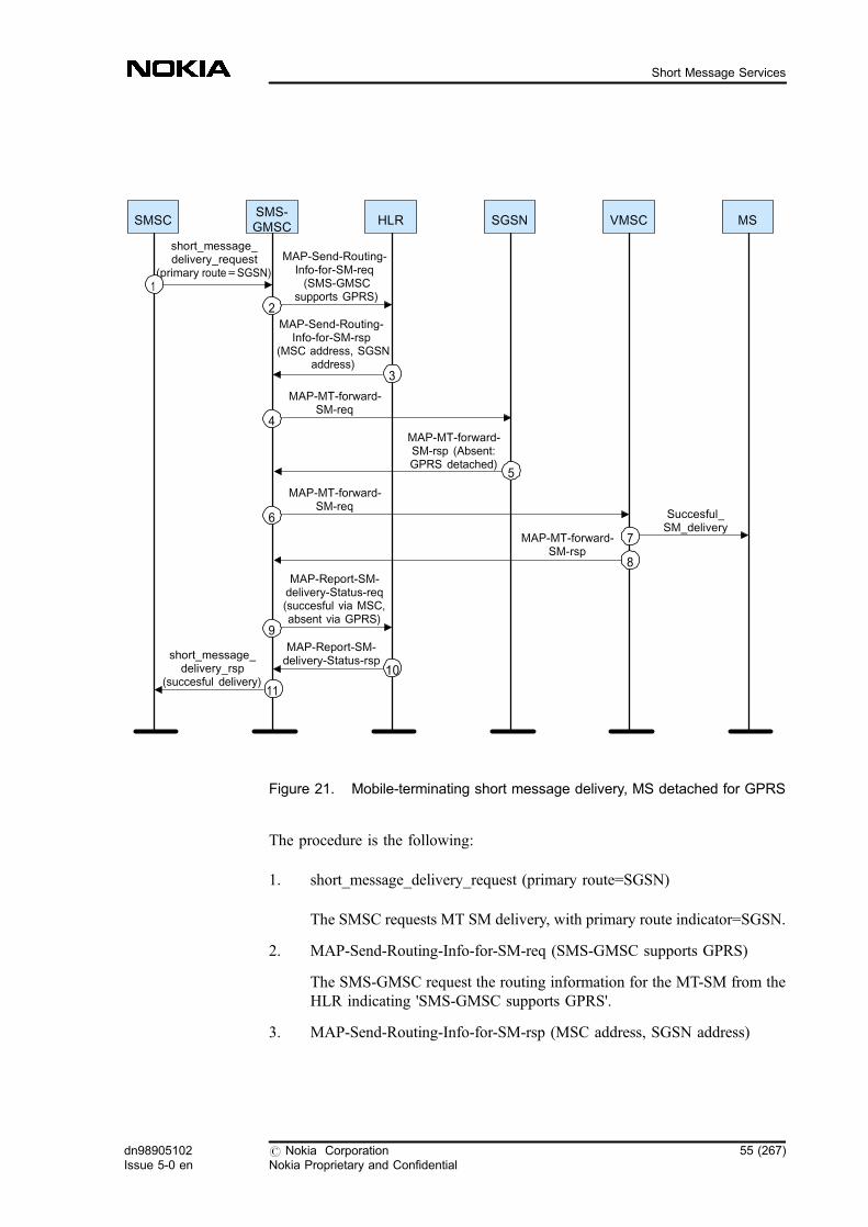
Figure 21. Mobile-terminating short message delivery, MS detached for GPRS
The procedure is the following:
1. short_message_delivery_request (primary route=SGSN)
The SMSC requests MT SM delivery, with primary route indicator=SGSN.
2. MAP-Send-Routing-Info-for-SM-req (SMS-GMSC supports GPRS)
The SMS-GMSC request the routing information for the MT-SM from theHLR indicating 'SMS-GMSC supports GPRS'.
3. MAP-Send-Routing-Info-for-SM-rsp (MSC address, SGSN address)
SMSC
short_message_delivery_request
(primary route=SGSN)
MAP-Send-Routing-Info-for-SM-req(SMS-GMSC
supports GPRS)
SMS-GMSC
HLR SGSN VMSC MS
1
10
2
3
MAP-Send-Routing-Info-for-SM-rsp
(MSC address, SGSNaddress)
4
MAP-MT-forward-SM-req
5
MAP-MT-forward-SM-rsp (Absent:GPRS detached)
6
MAP-MT-forward-SM-req
7
Succesful_SM_delivery
8
MAP-MT-forward-SM-rsp
MAP-Report-SM-delivery-Status-req(succesful via MSC,absent via GPRS)
9MAP-Report-SM-delivery-Status-rsp
11
short_message_delivery_rsp
(succesful delivery)
dn98905102Issue 5-0 en
# Nokia CorporationNokia Proprietary and Confidential
55 (267)
Short Message Services

SMS-GMSC receives two addresses from HLR: the VMSC address andthe SGSN address.
4. MAP-MT-forward-SM-req
Since the route indicator received from SMSC tells that the GPRS networkis the primary route, the SMS-GMSC first tries to deliver the MT-SMthrough GPRS network using the SGSN address received.
5. MAP-MT-forward-SM-rsp (Absent: GPRS detached)
MT-SM delivery was unsuccessful through GPRS network because thesubscriber is detached. The SMS-GMSC receives the reason forunsuccessful delivery.
6. MAP-MT-forward-SM-req
SMS-GMSC tries to deliver the MT-SM through the secondary route, thatis, the VMSC.
7. Successful_SM_delivery
The MT-SM is successfully delivered through the VMSC to the subscriber.
8. MAP-MT-forward-SM-rsp
The VMSC informs the SMS-GMSC about the successful delivery of theMT-SM.
9. MAP-Report-SM-delivey-Status-req (successful through MSC, absentthrough GPRS)
SMS-GMSC reports the delivery status, informing the HLR that the MT-SM was successfully delivered through the VMSC and failed through theGPRS network, because the subscriber was absent.
10. MAP-report-SM-delivery-Status-rsp
HLR acknowledges the report.
11. short_message_delivery_rsp (successful delivery)
SMS-GMSC informs the SMSC that the MT-SM delivery was successful.
SGSN and MSC address handling in the HLR and SMS-GMSC
If the subscriber has both SGSN and MSC addresses in the HLR, the HLR canreturn one or both of them in response to the MAP-Send-Routing-Info-for-SM.
56 (267) # Nokia CorporationNokia Proprietary and Confidential
dn98905102Issue 5-0 en
SMS Guide
. The HLR is allowed to return both the MSC address and the SGSN addressin case that:
- the SMS-GMSC indicates in the request that it supports the GPRSSM delivery and
- subscriber-specific HLR parameter 'network access mode' is set toBOTH and
- 'MT-SM through GPRS suppressed' is set OFF for that subscriber.
. The HLR might return only the MSC address in case that:
- the SMS-GMSC does not indicate the support of GPRS SMdelivery, and MT-SM through SGSN is set to MSC, and networkaccess mode is set to BOTH, or
- 'MT-SM through GPRS suppressed' is set ON for subscriber in theHLR, or
- 'network access mode' is set to MSC for the subscriber in the HLR.
. The HLR might return only the SGSN address in case that:
- the SMS-GMSC does not indicate the support of GPRS SM deliveryand MT-SM through SGSN is set to SGSN and 'network accessmode' is set to BOTH, or
- the SMS-GMSC indicates in the request that it supports the GPRSSM delivery and 'MT-SM through GPRS suppressed' is set OFF forsubscriber in HLR and 'network access mode' is set to BOTH orGPRS, or
- 'network access mode' is set to GPRS for subscriber in HLR.
If MNRG , MNRF , 'SGSN area restricted', and 'MSC area restricted' flags in thesubscriber data indicate that the subscriber is not reachable through either theSGSN and/or the MSC, then the HLR does not return that address, respectively.
When the SMS-GMSC receives two addresses, on the basis of the indicatorreceived from SMSC or if not available, on the basis of an operator-controlledparameter it determines whether the GPRS or CS network is the primary route totry the delivery. If the MS is not reachable through the primary route (forexample, the subscriber is detached or unidentified), the secondary route is tried.
If the delivery was unsuccessful through one or both the routes, or if the deliverywas successful for a priority short message, the delivery status is reported to theHLR, and MNRF and MNRG flags are set accordingly. Also the MNRR is setaccording to the absent subscriber diagnostic received from the SMS-GMSC.
dn98905102Issue 5-0 en
# Nokia CorporationNokia Proprietary and Confidential
57 (267)
Short Message Services
If the MT-SM delivery was successful through either of the routes, SMSC isinformed only of the successful delivery. If there is only one route available andthe MT-SM delivery failed, the error situation is indicated also to the SMSC. Ifthe delivery failed both through MSC and through SGSN, the error codes of bothroutes are indicated to the SMSC.
You can select the primary route by defining the option in the SMS-GMSC(GPRS_SUPP_IN_SMSGMSC ). However, if the SMSC indicates the primaryroute to the SMS-GMSC, it overrides this option.
Parameters needed for sending SM over GPRS
Subscriber-specific parameters:
network access mode:It is used to indicate if the subscriber has access to both theCS (MSC) and the GPRS (SGSN) networks, or only to one ofthem.
MT-SM through GPRS suppressed:It is used to suppress the SGSN route for the subscriber.
MT-SM through GPRS:It indicates if the MT-SM should be sent through the MSC orthrough the SGSN if the SMS-GMSC does not support GPRSSM delivery (that is, the GPRS_SUPP_IN_SMSGMSC is setto zero). The value of this parameter has an effect only whennetwork access mode is 'access to both networks' and the 'MT-SM through GPRS suppressed' parameter is OFF.
Network-specific parameters:
GPRS_SUPP_IN_SMSGMSC:It is used for the activation/deactivation of the service. It alsostates the primary route through which the mobile-terminatingshort message service (MT-SMS) is sent (MSC or SGSN), incase the Short Message Service Centre (SMSC) does notprovide the primary route indicator.
If its value is 0, it means that the SMS-GMSC can receiveonly one address in response to MAP-Send-Routing-Info-for-SM. If its value is 1, the SMS-GMSC can receive both MSCand SGSN address in response to MAP-Send-Routing-Info-for-SM, the primary route is SGSN. If its value is 2, the SMS-GMSC can receive both the MSC and the SGSN address inresponse to MAP-Send-Routing-Info-for-SM, the primaryroute is MSC.
58 (267) # Nokia CorporationNokia Proprietary and Confidential
dn98905102Issue 5-0 en
SMS Guide
GPRS_V2_IN_USE:It indicates the activation status of GPRS v2.
For related information, see SMS-related general parameter file (PRFILE/FIFILE) parameters .
Mobile-originating short message service over GPRS
If the MS is GPRS-attached, it sends the short message through SGSN to theSMS-IWMSC which forwards them to the short message service centre.Subscription check is done in the SGSN according to the data received from theHLR in the GPRS location update.
Ready for SM indication in SGSN
When the MS informs the HLR of its presence through SGSN (Gr interface), theMNRG flag is reset and the SMSCs, if there are any SMSC addresses in the HLRdatabase, are alerted. Note that it is possible that a MNRG or a MNRF flag is setin the database even if there are no SMSC addresses. The reason is that the MScan become reachable through SGSN and still remain not reachable through MSC(or vice versa).
For further information, see MAP in SMS , and Comparative example of SMSover GPRS with MAP version 2 and MAP version 3 .
1.12.3 Comparative example of SMS over GPRS with MAP version 2 andMAP version 3
Generally, the MT-SMS with MAP version 3 includes ten basic steps as describedin the following figure.
dn98905102Issue 5-0 en
# Nokia CorporationNokia Proprietary and Confidential
59 (267)
Short Message Services
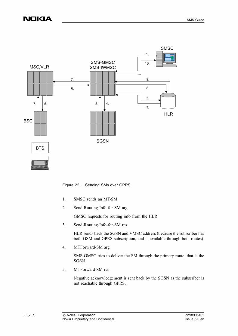
Figure 22. Sending SMs over GPRS
1. SMSC sends an MT-SM.
2. Send-Routing-Info-for-SM arg
GMSC requests for routing info from the HLR.
3. Send-Routing-Info-for-SM res
HLR sends back the SGSN and VMSC address (because the subscriber hasboth GSM and GPRS subscription, and is available through both routes)
4. MTForward-SM arg
SMS-GMSC tries to deliver the SM through the primary route, that is theSGSN.
5. MTForward-SM res
Negative acknowledgement is sent back by the SGSN as the subscriber isnot reachable through GPRS.
BSC
MSC/VLRSMS-GMSCSMS-IWMSC
SMSC
SGSN
HLR
BTS
1.
2.
3.4.5.
6.
7.
8.
9.
10.
6.7.
60 (267) # Nokia CorporationNokia Proprietary and Confidential
dn98905102Issue 5-0 en
SMS Guide
6. MTForward-SM arg
SMS-GMSC tries to deliver the SM through the secondary route, that is theMSC/VLR.
7. MTForward-SM res
Positive acknowledgement is sent back by the MSC/VLR as the SM wassuccessfully delivered to the subscriber.
8. Report-SM-Delivery-Status arg
Successful delivery through the MSC/VLR is reported to the HLR.
9. Report-SM-Delivery-Status res
HLR acknowledges the receipt of successful delivery status.
10. SMS-GMSC acknowledges the SM delivery to the SMSC.
If a subscriber has both GSM and GPRS subscription, the subscriber isrecognized in the HLR as being available through both SGSN and MSC, theprimary route indicator set by you is GPRS and the default route in the HLR is setto GPRS, then the main differences between the short message service overGPRS with MAP version 2 and MAP version 3 are the followings:
MAP version 2
An MT-SM is sent from the SMSC, the SMS-GMSC request for routinginformation, and the HLR sends back the SGSN address. The delivery throughSGSN is tried but since the subscriber is absent, an AbsentSubscriber DeliveryOutcome is sent back to the HLR. The HLR sets the MNRG flag, and the SMS-GMSC sends back a negative acknowledgement to the SMSC. (The SMSC waitsfor AlertSC , or retries delivering the SM according to the SMSC`s RetryTablevalue for AbsentSubscriber.) If a second SM is sent to the same subscriber, theHLR finds that the MNRG is set, and as the GPRS is set to be the primary route itsends a SendRoutingInfoForSM negative acknowledgement. The GSM route isnot tried, and any SM can be delivered only when the subscriber becomes activethrough GPRS again.
It means that although the subscriber is available through GSM, the SM iswaiting in the SMSC until the subscriber is GPRS attached again.
MAP version 3
dn98905102Issue 5-0 en
# Nokia CorporationNokia Proprietary and Confidential
61 (267)
Short Message Services
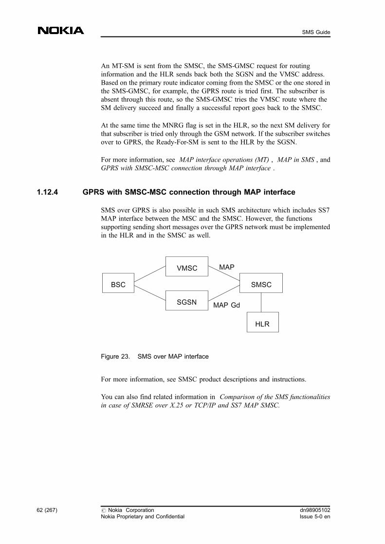
An MT-SM is sent from the SMSC, the SMS-GMSC request for routinginformation and the HLR sends back both the SGSN and the VMSC address.Based on the primary route indicator coming from the SMSC or the one stored inthe SMS-GMSC, for example, the GPRS route is tried first. The subscriber isabsent through this route, so the SMS-GMSC tries the VMSC route where theSM delivery succeed and finally a successful report goes back to the SMSC.
At the same time the MNRG flag is set in the HLR, so the next SM delivery forthat subscriber is tried only through the GSM network. If the subscriber switchesover to GPRS, the Ready-For-SM is sent to the HLR by the SGSN.
For more information, see MAP interface operations (MT) , MAP in SMS , andGPRS with SMSC-MSC connection through MAP interface .
1.12.4 GPRS with SMSC-MSC connection through MAP interface
SMS over GPRS is also possible in such SMS architecture which includes SS7MAP interface between the MSC and the SMSC. However, the functionssupporting sending short messages over the GPRS network must be implementedin the HLR and in the SMSC as well.
Figure 23. SMS over MAP interface
For more information, see SMSC product descriptions and instructions.
You can also find related information in Comparison of the SMS functionalitiesin case of SMRSE over X.25 or TCP/IP and SS7 MAP SMSC.
MAP
MAP Gd
BSC
VMSC
SGSN
SMSC
HLR
62 (267) # Nokia CorporationNokia Proprietary and Confidential
dn98905102Issue 5-0 en
SMS Guide

1.13 IN Short Message functionality
There is a Nokia-specific INAP interface between the MSC and the SCP whichrealises the IN SMS. It means that the subscriber can benefit the servicesprovided by the SCP only when inside the HPLMN .
The SMS triggering detection points (MO-, MT-, Status Report) make IN servicespossible for example, redirecting of short messages to another subscriber, orallowing the user to prevent short messages from a certain source. Also, EventDetection Points have been introduced for MO-, MT- and Status Report TDP.
The triggers defined for the IN SMS are located in the VMSC .
Mobile-originating IN SMS
In the MO case, the TDP is met after the authentication and ciphering for theMO-SMS has been carried out and the MSC has received the SM from the MS. Ifthe TDP is armed (the TDP data is included in the subscriber data), the MSC/VLR sends an IN service request to the SCP , which can react in several ways. Inthe following cases, the SM transfer continues:
. The SCP responds with the Continue message, and does not change theSM. The MSC/VLR forwards the original SM to the original SMS-IWMSC .
. The SCP responds with the Connect message. The SCP can change thedestination, both the SMSC address and subscriber B to whom the messagewas originally sent. The SCP can also change other parameters in the SMheader, for example, the type of the message. When receiving the changedheader from the SCP, the MSC/VLR alters the original SM header andsends the message to the SMS-IWMSC.
. The SCP arms one or both EDPs (successful or failure), or can request themonitoring mode. The type of the EDPs can be either notification (EDP-N) or request (EDP-R ).
. The SCP sends the FurnishChargingInformation message(s) related to theConnect or Continue message. When the MSC/VLR receives this message,it generates the IN CDR .
SM transfer is rejected if the SCP sends the ReleaseCall message. In this case, theMSC/VLR does not forward the SM to the SMS-IWMSC.
dn98905102Issue 5-0 en
# Nokia CorporationNokia Proprietary and Confidential
63 (267)
Short Message Services

Mobile-terminating IN SMS / Status Report SMS
In the MT case, the TDP is met at the earliest possible point after the MSC hasreceived the SM from the SMS-GMSC , and the subscriber data in the VLR hasbeen checked. If the TDP is armed (the TDP data is included in the subscriberdata), the MSC/VLR sends an IN service request to the SCP , which can react inseveral ways. In the following cases, the SM transfer continues:
. The SCP responds with the Continue message and does not change theSM. The transfer continues normally, and the MSC/VLR starts paging, andforwards the SM to the MS.
. The SCP can change the A-subscriber's address, or can send it back to theSSP (changed/unchanged) in a MT-Connect operation (MT-VMSC). Thatis, the mobile terminated SM (derived from the Connect case) can containalso the A subscriber's address in the originating address field, whichmakes improved SMS-based services, for example banking servicesavailable
. If the SCP wants to reroute the SM, it responds with the Connect message.The SCP can provide the address of the SMSC, or the A-, and B-subscriber's addresses as well. The SCP also changes the message headerof the SM. The SCP must change the SMS type from mobile-terminatingto mobile-originating before forwarding it to the specified SMS-IWMSC.
MSC/VLR can receives three different kind of SM Header from SCP.These are the following:
- When the MSC/VLR has received the Connect message, it generatesthe MO short message and forwards it to the specified IWMSC.After receiving the acknowledgement from the IWMSC, the MSCcan report the success of the transfer to the GMSC. The event is notreported to the SCP if the EDP has been armed in MT/SR-SMSConnect case. In that case the MSC/VLR disarms the request of theSCP. If the short message transfer to the SMSC is unsuccessful, theMSC reports an error back to the GMSC. The event is not reportedto the SCP if the EDP has been armed in MT/SR-SMS Connectcase. In that case the MSC/VLR disarms the request of SCP.
- When the MSC/VLR has received the Connect message with MT-Header (SMS DELIVER) , it delivers the MT�SM to the mobilesubscriber. After receiving the acknowledgement from the MS, theMSC reports the success or failure of the transfer to the SCP,depending on whether the EDPs are armed or not.
- When the MSC/VLR has received the Connect message with Statusreport-Header (SMS REPORT), it delivers the status report to themobile subscriber. After receiving the acknowledgement from MS,the MSC reports the success or failure of the transfer to the SCP,depending on whether the EDPs are armed or not.
64 (267) # Nokia CorporationNokia Proprietary and Confidential
dn98905102Issue 5-0 en
SMS Guide

The SCP can also arm EDP s (of either notification or request type), or canrequest the monitoring mode.
SM transfer is rejected if the SCP responds with the ReleaseCall message. TheMSC/VLR does not forward the SM to the MS. Before sending the ReleaseCallmessage, the SCP can arm the EDP(s). It can also sendFurnishChargingInformation message(s) but no IN CDR is created.
For more information, refer to the feature description of Feature 910: IN ShortMessage Service .
For further information, see Interworking between CAMEL SM and IN SM .
Activation information can be found in Handling of IN SMS .
1.14 CAMEL short message service
CAMEL (Customised Applications for Mobile network Enhanced Logic) is a toolto provide operator-specific services independently of the serving network.
In CAMEL SMS there is a standardized CAP interface between the MSC and theSCP . In this case the subscriber can benefit from the services provided by theSCP even when roaming outside the HPLMN .
With CAMEL improved control of MO-SM is possible. The VPLMN shall beable to detect a SMS set-up request and the CSE shall be able to modify thehandling of the SMS set-up request. If the subscriber is provided with CAMELbased SMS MO service, at SMS set-up, the VPLMN suspends SMS processing,makes contact with the CSE and waits for further instructions. When theVPLMN has made contact with the CSE, the CSE is able to instruct the VPLMNto include information received from the CSE in charging records and/or toactivate other control service events for the SM submission (Unsuccessful SMSubmission). Once the CSE has concluded issuing the above instructions, itissues one of the following instructions:
. bar the SM submission
. allow the submission to continue unchanged
. allow the SMS processing with modified information (called party number,calling party number, SMSC address)
dn98905102Issue 5-0 en
# Nokia CorporationNokia Proprietary and Confidential
65 (267)
Short Message Services
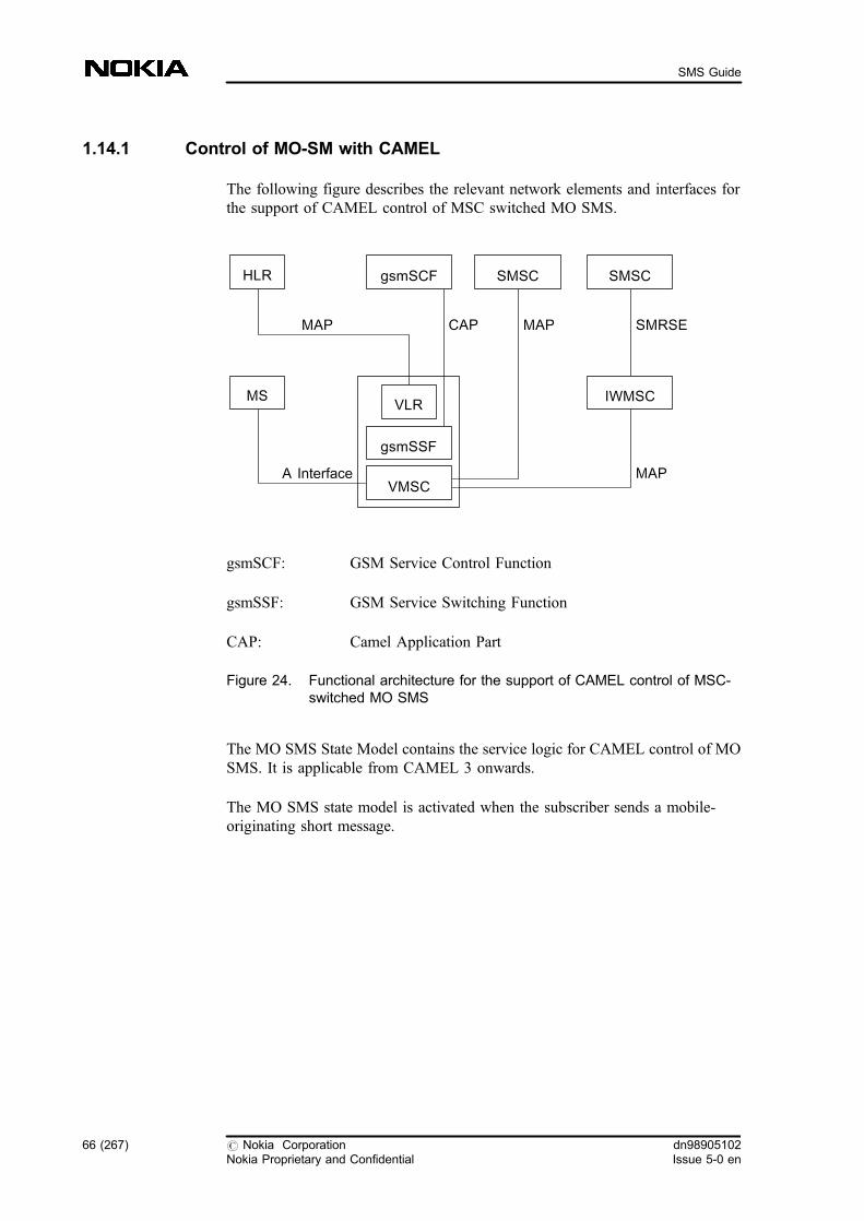
1.14.1 Control of MO-SM with CAMEL
The following figure describes the relevant network elements and interfaces forthe support of CAMEL control of MSC switched MO SMS.
gsmSCF: GSM Service Control Function
gsmSSF: GSM Service Switching Function
CAP: Camel Application Part
Figure 24. Functional architecture for the support of CAMEL control of MSC-switched MO SMS
The MO SMS State Model contains the service logic for CAMEL control of MOSMS. It is applicable from CAMEL 3 onwards.
The MO SMS state model is activated when the subscriber sends a mobile-originating short message.
MAP CAP SMRSE
A Interface
MAP
MAP
VLR
VMSC
gsmSSF
IWMSC
SMSC
MS
HLR gsmSCF SMSC
66 (267) # Nokia CorporationNokia Proprietary and Confidential
dn98905102Issue 5-0 en
SMS Guide

Figure 25. MO SMS state model
The detection points (DPs) of the model:
Table 6. DPs used for the MO SMS State Model
CAMEL DP DP Type Use of the DP
SMS_Collected_Info TDP-R Indication that the SMS-CSI is analysed and a mobile-originating short message is received.
The gsmSCF can control short message processingwith the following operations: ConnectSMS,ContinueSMS, ReleaseSMS, ResetTimerSMS,RequestReportSMSEvent,FurnishChargingInformationSMS.
O_SMS_Failure EDP-N
EDP-R
Indication that the short message submission to theSMSC has failed.
O_SMS_Submitted EDP-N
EDP-R
Indication that the short message has beensuccessfully delivered to the SMSC.
For more information refer to feature description of Features 1148 and 1159:CAMEL Phase 3 .
SMS_Null_&_Start_&Authorize
SMS_Exception
DP SMS_Collected_Info
DP O_SMS_Submitted O_SMS_Exception
DP O_SMS_Failure
SMS_Analyse & Routing
dn98905102Issue 5-0 en
# Nokia CorporationNokia Proprietary and Confidential
67 (267)
Short Message Services
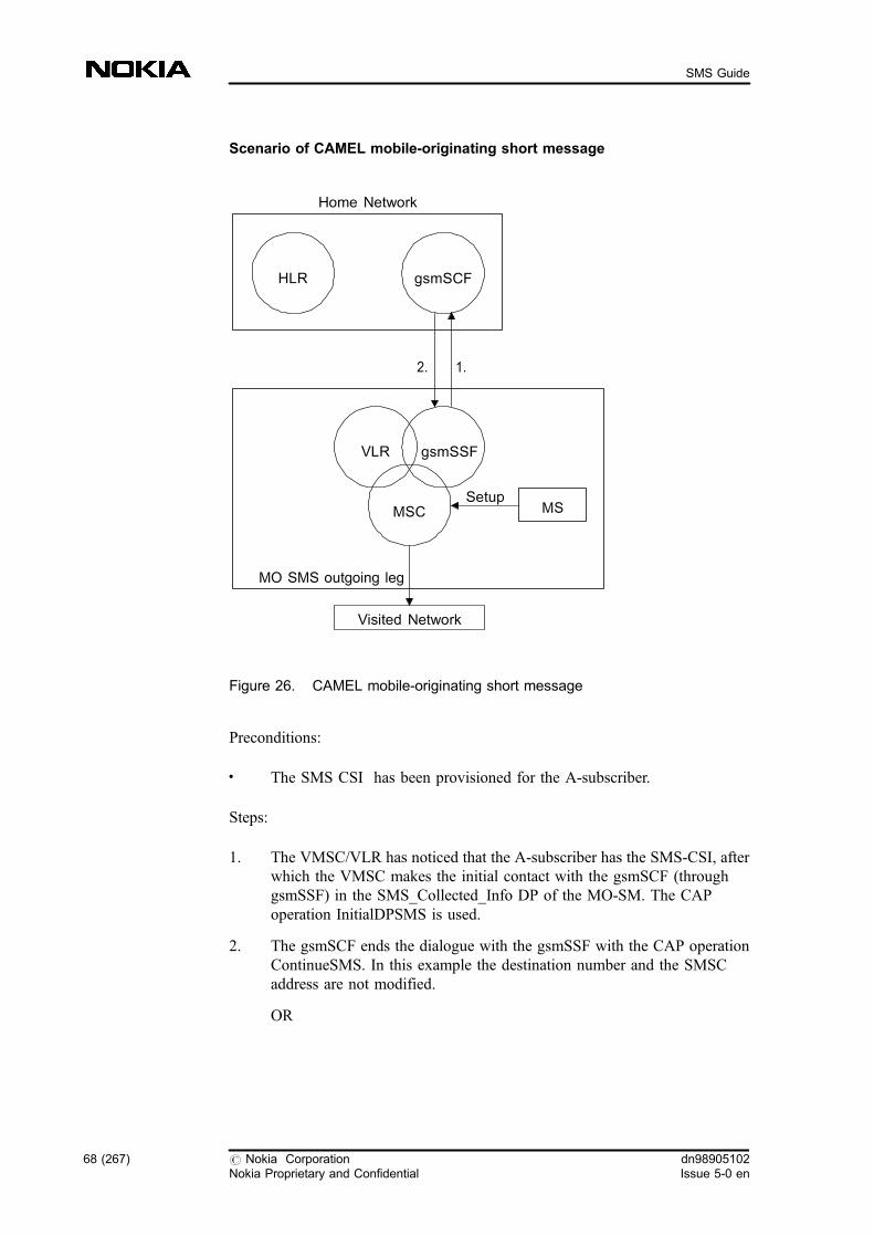
Scenario of CAMEL mobile-originating short message
Figure 26. CAMEL mobile-originating short message
Preconditions:
. The SMS CSI has been provisioned for the A-subscriber.
Steps:
1. The VMSC/VLR has noticed that the A-subscriber has the SMS-CSI, afterwhich the VMSC makes the initial contact with the gsmSCF (throughgsmSSF) in the SMS_Collected_Info DP of the MO-SM. The CAPoperation InitialDPSMS is used.
2. The gsmSCF ends the dialogue with the gsmSSF with the CAP operationContinueSMS. In this example the destination number and the SMSCaddress are not modified.
OR
HLR gsmSCF
1.2.
VLR
MSC
gsmSSF
MSSetup
MO SMS outgoing leg
Visited Network
Home Network
68 (267) # Nokia CorporationNokia Proprietary and Confidential
dn98905102Issue 5-0 en
SMS Guide

The gsmSCF ends the dialogue with the gsmSSF with the CAP operationReleaseSMS. In this case the MSC does not submit the MO-SM towardsthe SMSC.
. The SCP arms one or both EDPs (successful or failure). The type of theEDPs can be either notification (EDP-N ) or request (EDP-R ).
. The SCP sends the FurnishChargingInformation message(s) related to theConnect or Continue message. When the MSC/VLR receives this message,it generates the IN CDR .
Scenario of CAMEL mobile-originating short message with modifieddestination
For the Scenario of mobile-originating short message with modified destination,see Figure Scenario of mobile-originating short message.
Note
Please note, that step 2 of Scenario of CAMEL mobile-originating short messagewith modified destination differs from step 2 of Scenario of CAMEL mobile-originating short message .
Precondition:
. The SMS-CSI has been provisioned for the A-subscriber.
Steps:
1. The VMSC/VLR has noticed that the A-subscriber has the SMS-CSI, afterwhich the VMSC makes the initial contact with the gsmSCF (throughgsmSSF) in the SMS_Collected_Info DP of the MO-SM. The CAPoperation InitialDPSMS is used.
2. The gsmSCF ends the dialogue with the gsmSSF with the CAP operationConnectSMS that instruct the gsmSSF to change the destination number.The short message is routed to the new destination.
dn98905102Issue 5-0 en
# Nokia CorporationNokia Proprietary and Confidential
69 (267)
Short Message Services
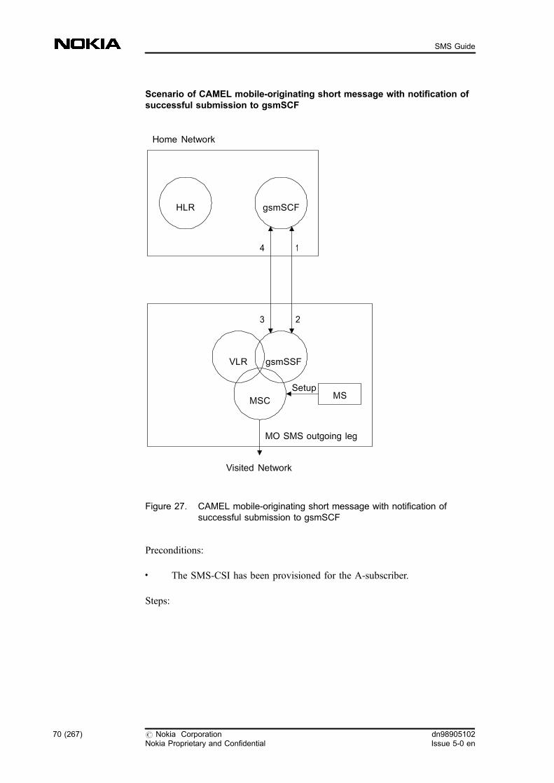
Scenario of CAMEL mobile-originating short message with notification ofsuccessful submission to gsmSCF
Figure 27. CAMEL mobile-originating short message with notification ofsuccessful submission to gsmSCF
Preconditions:
. The SMS-CSI has been provisioned for the A-subscriber.
Steps:
HLR gsmSCF
1
2
VLR
MSC
gsmSSF
MSSetup
MO SMS outgoing leg
Visited Network
Home Network
4
3
70 (267) # Nokia CorporationNokia Proprietary and Confidential
dn98905102Issue 5-0 en
SMS Guide

1. The VMSC/VLR has noticed that the A-subscriber has the SMS-CSI, afterwhich the VMSC makes the initial contact with the gsmSCF (throughgsmSSF) in the SMS_Collected_Info DP of the MO-SM. The CAPoperation InitialDPSMS is used.
2. The gsmSCF arms the detection points O_SMS_Submitted andO_SMS_Failure in the notify mode (EDP-N) with theRequestReportSMSEvent operation.
3. The gsmSCF sends the ContinueSMS or ConnectSMS operation. In thisexample the destination number and the SMSC address are not modified.
4. When the O_SMS_Submitted DP is met (that is, the SM was successfullydelivered to the SMSC), the gsmSSF sends the EventReportSMS (Notifyand Continue) operation to the gsmSCF. After this the relationship isterminated.
OR
When the O_SMS_Failure DP is met (that is, the SM delivery to the SMSCwas unsuccessful), the gsmSSF sends the EventReportSMS (Notify andContinue) operation to the gsmSCF. After this the relationship isterminated.
For more information, refer to the feature description of Features 1148 and 1159:CAMEL Phase 3 .
SMS reference number
The SMS reference number makes it possible to correlate the SMS Call DetailedRecords (CDR) produced by the MSC/SGSN with the SMS CDRs produced bythe Service Control Point (SCP) for Camel Control of MO SMS.
1.14.2 Control of MT-SM with CAMEL
The following figure describes the relevant network elements and interfaces forthe support of CAMEL control of MSC switched MT SMS.
dn98905102Issue 5-0 en
# Nokia CorporationNokia Proprietary and Confidential
71 (267)
Short Message Services

gsmSCF: GSM Service Control Function
gsmSSF: GSM Service Switching Function
CAP: Camel Application Part
Figure 28. Functional architecture for the support of CAMEL control of MSC-switched MT SMS
The MT SMS state model contains the service logic for CAMEL control of MTSMS. It is applicable from CAMEL 4 onwards.
MAP CAP SMRSE
A Interface
MAP
MAP
VLR
VMSC
gsmSSF
GMSC
SMSC
MS
HLR gsmSCF SMSC
72 (267) # Nokia CorporationNokia Proprietary and Confidential
dn98905102Issue 5-0 en
SMS Guide

Figure 29. MT SMS state model
The detection points (DPs) of the model:
Table 7. DPs used for the MT-SMS state model
CAMEL detection point DP type Description
DP SMS Delivery Request TDP-R Indication that the MT-SMS-CSI isanalysed and a mobile-terminatingshort message is received.
DP T_SMS_Failure EDP-N
EDP-R
Indication that the SM delivery tothe MS has failed.
DP T_SMS_Delilvered EDP-N
EDP-R
Indication that the SM has beensuccessfully delivered to the MS.
For more information refer to the feature description of Feature 1364: MT-SM forCAMEL Phase 4 .
SMS Null & Start &Authorize
SMS_Exception
SMS Delivery
DP SMS_Delivery_Request
DP T_SMS_Delivered
DP T_SMS_Failure
T_SMS_Exception
dn98905102Issue 5-0 en
# Nokia CorporationNokia Proprietary and Confidential
73 (267)
Short Message Services
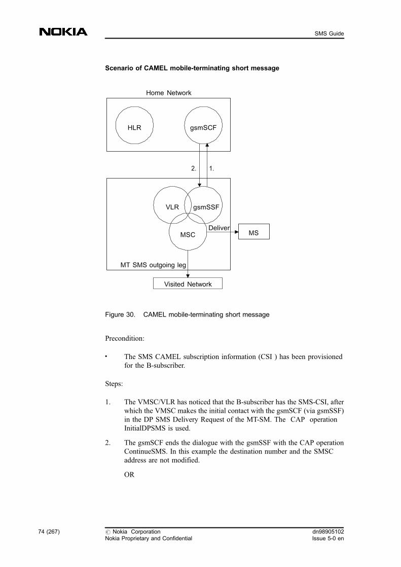
Scenario of CAMEL mobile-terminating short message
Figure 30. CAMEL mobile-terminating short message
Precondition:
. The SMS CAMEL subscription information (CSI ) has been provisionedfor the B-subscriber.
Steps:
1. The VMSC/VLR has noticed that the B-subscriber has the SMS-CSI, afterwhich the VMSC makes the initial contact with the gsmSCF (via gsmSSF)in the DP SMS Delivery Request of the MT-SM. The CAP operationInitialDPSMS is used.
2. The gsmSCF ends the dialogue with the gsmSSF with the CAP operationContinueSMS. In this example the destination number and the SMSCaddress are not modified.
OR
HLR gsmSCF
1.2.
VLR
MSC
gsmSSF
MSDeliver
MT SMS outgoing leg
Visited Network
Home Network
74 (267) # Nokia CorporationNokia Proprietary and Confidential
dn98905102Issue 5-0 en
SMS Guide
The gsmSCF ends the dialogue with the gsmSSF with the CAP operationReleaseSMS. In this case the MSC does not submit the MT-SM towardsthe SMSC.
The SCP arms one or both EDPs (successful or failure). The type of the EDPs canbe either notification (EDP-N ) or request (EDP-R ).
Scenario of CAMEL mobile-terminating short message with modifieddestination
Precondition:
. The MT-SMS-CSI has been provisioned for the B-subscriber.
Steps:
. The VMSC/VLR has noticed that the B-subscriber has the MT-SMS-CSI,after which the VMSC makes the initial contact with the gsmSCF (viagsmSSF) in the SMS_Delivery_Request DP of the MT-SM. The CAPoperation InitialDPSMS is used.
. The gsmSCF ends the dialogue with the gsmSSF with the CAP operationConnectSMS that instruct the gsmSSF to change the Calling Party address.The short message is delivered to subscriber B.
Note
The Called Party Address and the SMSC address can not be changed.
SMS reference number
The SMS reference number makes it possible to correlate the SMS Call DetailedRecords (CDR) produced by the MSC/SGSN with the SMS CDRs produced bythe Service Control Point (SCP) for Camel Control of MT SMS.
1.14.3 Interworking between CAMEL SM and IN SM
IN Short Message Service (feature 910) has a proprietary functionality which issimilar to the SMS part of CAMEL 3 and CAMEL 4. For more details, see INshort message functionality .
dn98905102Issue 5-0 en
# Nokia CorporationNokia Proprietary and Confidential
75 (267)
Short Message Services
When the subscriber is roaming, CAMEL 3 CAMEL 4 are the features that canbe active. When the subscriber is in the Home PLMN, the following case casescan be distinguished:
. If the IN functionality MO DP is set for the subscriber, the IN MOfunctionality takes precedence over CAMEL 3. If you want CAMEL 3 towork for that subscriber also in the HPLMN, you have to set off Feature910: IN Short Message Service MO DP for that subscriber.
. When IN functionality MT DP is set for the subscriber, IN MTfunctionality will take precedence over CAMEL 4. If you want CAMEL 4to work for that subscriber also in the HPLMN, you have to set off Feature910: IN Short Message Service MT DP for that subscriber.
1.15 Short message routing
Most of the operators have GSM network with more than one SMSC. This meansthat services offered by one SMSC are not the same as those offered by anotherSMSC.
For example, one SMSC can be dedicated for MO-MTs and voice mail alertservices, and another for e-mail, telefax, and for accessing service providerservices (such as weather, stock market information), and so on. This is confusingfor the subscribers, because if they want to use all the services, they should notonly know many SMSC addresses, but also remember to change the address inthe MS before using the services.
A solution for overcoming this is to always use the same SMSC address in theMS, and to configure the VMSC in a way that the MO-SM is routed to the rightSMSC in the PLMN. This is possible only if the MSC is able to solve thedestination application from the MO-SM. The standard procedure for this is touse a PID (Protocol Identifier).
The MML command for creating SMS routing analysis is CFE . For example,when sending an MO-SM, the subscriber selects the appropriate PID value (forexample, telefax, X.400), after which the MSC should know in which SMSC theapplication exists.
76 (267) # Nokia CorporationNokia Proprietary and Confidential
dn98905102Issue 5-0 en
SMS Guide

Figure 31. SMS routing
However, the PID alone is not enough, because there are applications which donot have PID values of their own.
In the Nokia VMSC you can solve this by using a Service Application Prefix(SAP). The Nokia SMSC also uses this prefix to differentiate between theapplications. Each application known by the SMSC has its own SAP. The SAPcan be, for example, 991 for service provider applications, 992 for e-mail, 993 fortelefax and so on. Note that in this way it is not necessary to change the PIDvalue for e-mail or telefax. The subscriber gives the SAP in the beginning of thedestination address, for example, weather reports could be requested by sending amessage to address '991 1000'. In this case, 991 indicates the service providerapplication, and 1000 the service (here: weather reports).
There is a table for MO-SM routing based on PIDs and/or SAPsin the MSC, andan MML for maintaining the table, as shown in the example below:
SMSC2 forfax and emailmessages
VMSC
fax MO-SMS
SMS-IWMSC2
1
SMS-IWMSC1
SMSC1 forMS-to-MSmessages
fax MO-SMS
2
1
normal MO-SMS 1
2 2
dn98905102Issue 5-0 en
# Nokia CorporationNokia Proprietary and Confidential
77 (267)
Short Message Services
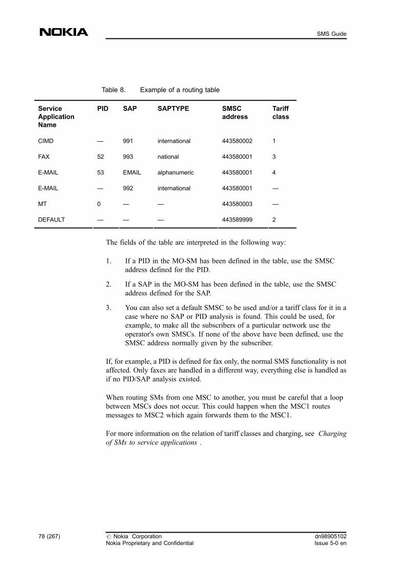
Table 8. Example of a routing table
ServiceApplicationName
PID SAP SAPTYPE SMSCaddress
Tariffclass
CIMD � 991 international 443580002 1
FAX 52 993 national 443580001 3
E-MAIL 53 EMAIL alphanumeric 443580001 4
E-MAIL � 992 international 443580001 �
MT 0 � � 443580003 �
DEFAULT � � � 443589999 2
The fields of the table are interpreted in the following way:
1. If a PID in the MO-SM has been defined in the table, use the SMSCaddress defined for the PID.
2. If a SAP in the MO-SM has been defined in the table, use the SMSCaddress defined for the SAP.
3. You can also set a default SMSC to be used and/or a tariff class for it in acase where no SAP or PID analysis is found. This could be used, forexample, to make all the subscribers of a particular network use theoperator's own SMSCs. If none of the above have been defined, use theSMSC address normally given by the subscriber.
If, for example, a PID is defined for fax only, the normal SMS functionality is notaffected. Only faxes are handled in a different way, everything else is handled asif no PID/SAP analysis existed.
When routing SMs from one MSC to another, you must be careful that a loopbetween MSCs does not occur. This could happen when the MSC1 routesmessages to MSC2 which again forwards them to the MSC1.
For more information on the relation of tariff classes and charging, see Chargingof SMs to service applications .
78 (267) # Nokia CorporationNokia Proprietary and Confidential
dn98905102Issue 5-0 en
SMS Guide

One consequence of SMS routing is that when the SMSCs send MT-SMs, they alluse individual SMSC addresses. However, they correspond to one logical SMSCaddress. This can cause problems with an MS if, when receiving status reports, itcompares this MT-SMS address with the original address stored in mobile setup.This can be solved by configuring the SMSC address used towards subscribers inthe SMS-GMSC . The same address that SMSC originally used in MT-SMSwhen setting the MWD must be used to make sure that alerts work correctly, thatis, they are sent from the HLR to the correct SMSC.
For more information see SMS management instructions in Configuring networkelements for SMS , and Managing SMS network element-specific data . See alsoWorking examples for SMS management .
The following figure describes how SMSC address are used in MT-SMS betweendifferent network elements:
Figure 32. SMSC address used in MT-SMS between different networkelements
SMS routing analysis
The decision whether the SMS routing analysis is executed or not in the VMSC,depends on the availability of Feature 1165: GSM Phase 2+ Enhancements . Theexecution of the analysis in the SMS-IWMSC is unconditional if you have thisfunction in use.
If you have feature 1165 in use in your network, the SMSC address is analysed byinvoking the SMS routing support analysis. This analysis indicates whether theSMS routing analysis should be executed or not.
Linetype means SMS transfer from SMSCA
Linetype means SMS transfer from SMSCB
SMSCB
SMSCA
SMSCB
SMSCA
SMSC
SMSC
SMSC A
SMSC B
SMS-GMSC HLR
VMSC
dn98905102Issue 5-0 en
# Nokia CorporationNokia Proprietary and Confidential
79 (267)
Short Message Services

If you do not have feature 1165 in use, the decision about executing the SMSrouting analysis is entirely based on the roaming status information received formthe VLR. The roaming status is determined from the IMSI of the subscriber in theVLR. If the roaming status is home network/home subscriber, the SMS routinganalysis is invoked.
Note
If the SMS routing support analysis function is not active, the VLR sets thesubscriber's roaming status by reading the status of HPLMN and home country(HCOUN) from the result record in the PLMN-specific parameter file and sendsit to the SMS application. If you set the home PLMNs in the PLMN-specificparameter file with the MXN command so that HPLMN=Y, HCOUN=Y, theroaming status will be 'HOME' despite the different network codes. This way theSMS routing analysis is executed for all home subscribers.
For further information, see Alphanumeric addressing of SMS-relatedapplications .
1.15.1 SMS routing enhancements
Routing of short messages is enhanced by:
. a change in the routing analysis
. the use of alphanumeric addresses
Note
MAP version 3 is needed for these functionalities. These enhancements areavailable if you have Feature 1165: Short Message Services, GSM Phase 2+Enhancements in your network. For details, refer to the feature activationinstructions of Feature 1165: Short Message Services, GSM Phase 2+Enhancements .
There is a change in the logic which defines when the routing analysis (based onPID or SAP) applies for a short message. As the protocol identifier and SAP aretightly related to the SMSC's function, this feature enables you to define anSMSC address on the basis of which the routing analysis is executed. If youdefine a need for the SMSC routing analysis, the routing analysis is executed.
80 (267) # Nokia CorporationNokia Proprietary and Confidential
dn98905102Issue 5-0 en
SMS Guide
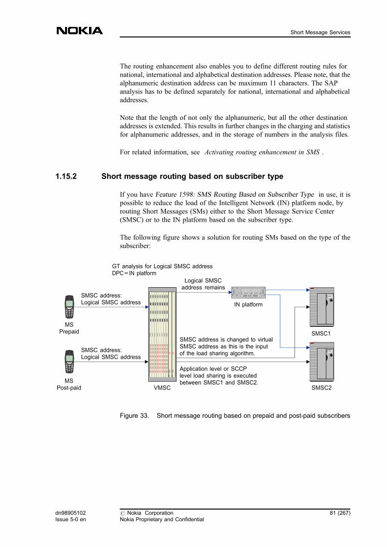
The routing enhancement also enables you to define different routing rules fornational, international and alphabetical destination addresses. Please note, that thealphanumeric destination address can be maximum 11 characters. The SAPanalysis has to be defined separately for national, international and alphabeticaladdresses.
Note that the length of not only the alphanumeric, but all the other destinationaddresses is extended. This results in further changes in the charging and statisticsfor alphanumeric addresses, and in the storage of numbers in the analysis files.
For related information, see Activating routing enhancement in SMS .
1.15.2 Short message routing based on subscriber type
If you have Feature 1598: SMS Routing Based on Subscriber Type in use, it ispossible to reduce the load of the Intelligent Network (IN) platform node, byrouting Short Messages (SMs) either to the Short Message Service Center(SMSC) or to the IN platform based on the subscriber type.
The following figure shows a solution for routing SMs based on the type of thesubscriber:
Figure 33. Short message routing based on prepaid and post-paid subscribers
SMSC address:Logical SMSC address
MSPrepaid
MSPost-paid
SMSC address:Logical SMSC address
VMSC
SMSC1
SMSC2
IN platform
Logical SMSCaddress remains
GT analysis for Logical SMSC addressDPC=IN platform
SMSC address is changed to virtualSMSC address as this is the inputof the load sharing algorithm.
Application level or SCCPlevel load sharing is executedbetween SMSC1 and SMSC2.
dn98905102Issue 5-0 en
# Nokia CorporationNokia Proprietary and Confidential
81 (267)
Short Message Services
By splitting the SM traffic of prepaid and post-paid subscribers, it is possible toroute Mobile-Originated Short Messages (MO-SMs) from the Home Public LandMobile Network (HPLMN) to the IN platform in case of a prepaid subscriber, ordirectly to the SMSC in case of a post-paid subscriber.
To route SMs depending on subscriber type, it is necessary that only one logicalSMSC address is used in the network, and that each subscriber is marked with theICK (IN category key) parameter if they are prepaid or post-paid subscribers.
The type of the subscriber is determined by checking the value of ICK parameter.If you use this feature, this value is shown in the Mobile-Originated ShortMessage Service Charging Records (SMMO CDR).
1.16 Sending SMS without SMSC
If you have Feature 1633: Direct SM Delivery in use, it is possible to providesolution for direct SM delivery without the involvement of the Short MessageService Centre (SMSC ).
This solution provides a considerable decrease in the load of the SMSC and alsothe MAP or SMRSE interface between the Mobile Services Switching Centre(MSC ) and the SMSC. In case of SMRSE SMSC, the load of the InterworkingMSC (IWMSC) and the Gateway MSC (GMSC ) is also reduced.
This feature is implemented in the Mobile-Originated Visited Mobile ServicesSwitching Centre (MO-VMSC).
If subscriber B is available and subscriber A is not roaming, the MO-VMSC candirectly deliver the MO-SM by converting it to an MT-SM, and forwarding it tothe proper Mobile-Terminated Visited Mobile Services Switching Centre (MT-VMSC) after the Home Location Register (HLR) enquiry.
In case of any error, the MO-VMSC forwards the MO-SM to the SMSC, and SMdelivery is carried out in the traditional way.
This solution also enables you to distinguish the direct SMs from normal SMs inthe SMS measurement and in the Charging Data Records (CDRs).
The decision on 'Non-store and forward' SM delivery without the SMSC is madeas follows:
82 (267) # Nokia CorporationNokia Proprietary and Confidential
dn98905102Issue 5-0 en
SMS Guide

1. The MO-VMSC receives a normal MO-SM from the subscriber.
2. The SMS application executes the IN interaction (if needed), and thebarring checking. It also checks if there is routing analysis for the B-number of the MO-SM.
Depending on whether there is routing analysis for the B-number, the SMcan be handled in the following ways:
. If there is analysis for the application terminated SM, the MO-SM isforwarded to the SMSC in the traditional way.
. If there is no analysis for the B-number of the MO-SM, the MSCdelivers the SM directly.
It is possible to check the Service Application Name (SAN) to decide if direct SMdelivery should be performed, if SMS routing analysis is used in the network alsofor MO-MT SMs (not just for MO-AT SMs).
For more information about possible parameter setting, see the feature descriptionof Feature 1633: Direct SM Delivery
Direct SM delivery
When direct SM delivery is performed, the SMS application sends positiveacknowledgement to the MS, which receives a 'Message sent' response. The SMSapplication also converts the MO-SM to an MT-SM, and starts the GMSCfunctionality. This means that the MSC makes the HLR enquiry and sends theForward-SM MAP operation to the correct MT-VMSC. The MT-VMSC deliversthe MT-SM in a normal way.
If the MT-SM delivery is not successful, the MT-VMSC sends back a negativeacknowledgement to the MT-GMSC/MO-VMSC. The MO-VMSC then forwardsthe SM to the SMSC. If DIRECT_SM_FAILURE_IND parameter is activated,the MO-VMSC sets the reserved value of Transport Protocol-Message TypeIndication (TP-MTI) field in the SUBMIT-MO-SM. If the SMSC supports thisfunctionality, it can handle the SM based on this reserved value as delayeddelivery, and the next delivery attempt will be based on the SMSC retry table.
If DIRECT_SM_STA_CHA_INFO parameter is activated, the SMSC address ofthe MO-SM is changed to the operator-predefined SMSC address, which allowsthat the SM delivered by the MSC can be differentiated from the normal SM inthe statistics reports and charging data records. When the MT-SM arrives in theMT-VMSC, the SMS application checks the SMSC address. If the SMSC addressof the MT-SM is the same as stored in the HRNFIL, the MT-SM is aDIRECTSM, which has to be indicated in the statistics and charging data records.
dn98905102Issue 5-0 en
# Nokia CorporationNokia Proprietary and Confidential
83 (267)
Short Message Services

The following figures illustrate the SMSC with MAP interface including theInterworking Mobile Services Switching Centre (IWMSC ) functionality. If theSMSC has SMRSE interface, the IWMSC is a separate network element, and it isnot affected by this feature.
1. SUBMIT-MO-SM
2. Checking SMS routing analysis (Application-terminated SM), andconverting MO-SM to MT-SM (GMSC functionality invoked)
3. SMS-SUBMIT-REPORT
4. SRI-FOR-SM
5. SRI-FOR-SM-ACK
6. MT-FORWARD-SM
7. SMS-DELIVER
8. SMS-DELIVER-REPORT
9. SMMT CDR, STATISTICS REPORT UPDATE
10. MT-FORWARD-SM-ACK
11. SMMT CDR from GMSC, STATISTICS REPORT UPDATE
12. SMMO CDR from MO-VMSC, STATISTICS REPORT UPDATE
13. MSC generates the status report, if it is requested
MO-VMSCMT-GMSC
MT-VMSC SMSC
HLR
4
5
6 10
1
3
7
8
122
13
11
9
84 (267) # Nokia CorporationNokia Proprietary and Confidential
dn98905102Issue 5-0 en
SMS Guide
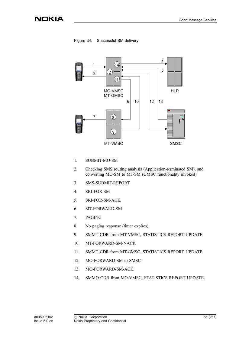
Figure 34. Successful SM delivery
1. SUBMIT-MO-SM
2. Checking SMS routing analysis (Application-terminated SM), andconverting MO-SM to MT-SM (GMSC functionality invoked)
3. SMS-SUBMIT-REPORT
4. SRI-FOR-SM
5. SRI-FOR-SM-ACK
6. MT-FORWARD-SM
7. PAGING
8. No paging response (timer expires)
9. SMMT CDR from MT-VMSC, STATISTICS REPORT UPDATE
10. MT-FORWARD-SM-NACK
11. SMMT CDR from MT-GMSC, STATISTICS REPORT UPDATE
12. MO-FORWARD-SM to SMSC
13. MO-FORWARD-SM-ACK
14. SMMO CDR from MO-VMSC, STATISTICS REPORT UPDATE
MO-VMSCMT-GMSC
MT-VMSC SMSC
HLR
4
5
6 10
1
3
7 8
2
14
11
9
12 13
dn98905102Issue 5-0 en
# Nokia CorporationNokia Proprietary and Confidential
85 (267)
Short Message Services

Figure 35. Unsuccessful SM delivery, no paging response
1. SUBMIT-MO-SM
2. Checking SMS routing analysis (Application-terminated SM), andconverting MO-SM to MT-SM (GMSC functionality invoked)
3. SMS-SUBMIT-REPORT
4. SRI-FOR-SM
5. SRI-FOR-SM-NACK (subscriber in detach state)
6. SMMT CDR from MT-GMSC, STATISTICS REPORT UPDATE
7. MO-FORWARD-SM to SMSC
8. MO-FORWARD-SM-ACK
9. SMMO CDR from MO-VMSC, STATISTICS REPORT UPDATE
Figure 36. Unsuccessful SM delivery, absent subscriber
MO-VMSCMT-GMSC
MT-VMSC SMSC
HLR
4
5
7 8
1
3 2
6
9
86 (267) # Nokia CorporationNokia Proprietary and Confidential
dn98905102Issue 5-0 en
SMS Guide

1.17 SMS Forwarding
Short Message Service Call Forwarding Unconditional (SMS CFU ) supportsSMS forwarding either to an active subscriber or to a subscriber who is currentlydetached. If you have Feature 626: Supplementary Services Phase 2 Extensionsin use, the subscriber can flexibly define the number to which the SM isforwarded.
SMS forwarding is an HLR-feature, but MAP version 3 must be supported in theHLR.
SMS CFU also works in situations where the subscriber receives an SM from aforeign PLMN.
1.17.1 Basic forwarded MT-SMS
The following figure shows the basic forwarded MT-SMS functionality.
Figure 37. Basic forwarded MT-SMS functionality
VMSC
SendRoutingInfoForSM
GMSC/SMSC HLR-B HLR-C
SendIMSI
SendIMSIAck
SendRoutingInfoForSM
SendRoutingInfoForSMAck
Inform-SC
SendRoutingInfoForSMAck
Inform-SC
MT-ForwardSM
MT-ForwardSMAck
dn98905102Issue 5-0 en
# Nokia CorporationNokia Proprietary and Confidential
87 (267)
Short Message Services
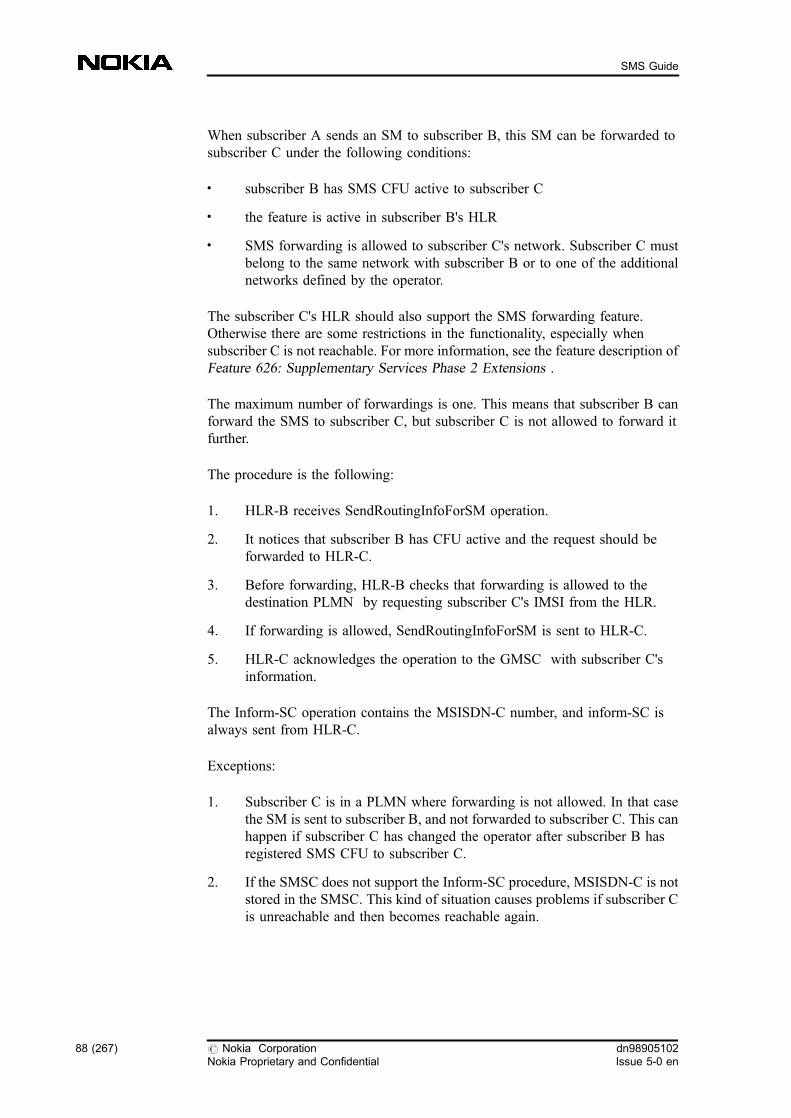
When subscriber A sends an SM to subscriber B, this SM can be forwarded tosubscriber C under the following conditions:
. subscriber B has SMS CFU active to subscriber C
. the feature is active in subscriber B's HLR
. SMS forwarding is allowed to subscriber C's network. Subscriber C mustbelong to the same network with subscriber B or to one of the additionalnetworks defined by the operator.
The subscriber C's HLR should also support the SMS forwarding feature.Otherwise there are some restrictions in the functionality, especially whensubscriber C is not reachable. For more information, see the feature description ofFeature 626: Supplementary Services Phase 2 Extensions .
The maximum number of forwardings is one. This means that subscriber B canforward the SMS to subscriber C, but subscriber C is not allowed to forward itfurther.
The procedure is the following:
1. HLR-B receives SendRoutingInfoForSM operation.
2. It notices that subscriber B has CFU active and the request should beforwarded to HLR-C.
3. Before forwarding, HLR-B checks that forwarding is allowed to thedestination PLMN by requesting subscriber C's IMSI from the HLR.
4. If forwarding is allowed, SendRoutingInfoForSM is sent to HLR-C.
5. HLR-C acknowledges the operation to the GMSC with subscriber C'sinformation.
The Inform-SC operation contains the MSISDN-C number, and inform-SC isalways sent from HLR-C.
Exceptions:
1. Subscriber C is in a PLMN where forwarding is not allowed. In that casethe SM is sent to subscriber B, and not forwarded to subscriber C. This canhappen if subscriber C has changed the operator after subscriber B hasregistered SMS CFU to subscriber C.
2. If the SMSC does not support the Inform-SC procedure, MSISDN-C is notstored in the SMSC. This kind of situation causes problems if subscriber Cis unreachable and then becomes reachable again.
88 (267) # Nokia CorporationNokia Proprietary and Confidential
dn98905102Issue 5-0 en
SMS Guide
1.17.2 Provisioning and activating SMS forwarding
SMS CFU is provisioned and activated separately from CFU. This means that ifCFU is provisioned or activated to all basic services by using MML commands,this does not include SMS forwarding.
You can give SMS at the same time with the provision of CFU or add CFU forSMS afterwards. If you give CFU for SMS, and the subscriber does not haveCFU, then the HLR automatically provides CFU for the subscriber. It is notpossible to provide CFU only for SMS. It is also not possible to remove SMSCFU separately, but the complete CFU must be removed. Create SMS basicservice to the subscriber before provisioning SMS CFU, otherwise the commandfails with error code 'Teleservice not provided'.
1.17.3 MMI procedures to activate SMS forwarding
The subscriber can manage SMS CFU by using the MMI of the mobile station(MS). If the MS understands these MMI strings (for example, activate, register),they are sent as GSM standard supplementary service operations. If the MS doesnot support these service codes, the subscriber cannot manage the service with theMS. The following MMI procedures can be used:
. **21*nbr*16# (RegisterSS)
. *21**16# (ActivateSS)
. ##21**16# (EraseSS)
. #21**16# (DeactivateSS)
. *#21**16# (InterrogateSS)
1.18 Same CLI for multiple subscribers
If you have Feature 1541: Same CLI for Multiple Subscribers in your network, itis possible that several mobile phones (IMSIs) use a common MSISDN numberwhen originating calls (voice or data) or sending short messages. The phones canbelong to one or more users.
The HLR stores the subscriber (IMSI) -related data under the so-called 'ownMSISDN' number. In the HLR, each subscriber has its own record, which isextended with an attribute. This attribute contains the 'common MSISDN'number. The own MSISDN number is a unique identifier, whereas the commonMSISDN number can belong to several records.
dn98905102Issue 5-0 en
# Nokia CorporationNokia Proprietary and Confidential
89 (267)
Short Message Services

The primary phone has the same own and common MSISDN number. In case ofan HLR query with the common MSISDN number, the primary IMSI-related datais retrieved and included in the response of the transaction. This means that theshort messages sent to the common MSISDN will reach the primary phone.
Depending on the visited PLMN's capability, either the own MSISDN number orthe common MSISDN number is transferred to the VLR/SGSN during a locationupdate as primary identifier (preconfigurable in the HLR). As an option, the CLIrestriction service can be set to hide the own MSISDN number in permanentmode if the PLMN does not support storing many records with the sameMSISDN number in the same VLR/SGSN. The CLI restriction, however, has noeffect on the 'CLI' included in MO-SM. Even if the common MSISDN is used asthe primary identifier, the own MSISDN number is still sent to the VLR as anormal subscriber attribute (in a proprietary extension).
The usage of Same CLI for multiple subscribers feature can have effect on SMSbased services. When the user sends short message from the non-primary phone(the own MSISDN is different from the common MSISDN) to a service centerrequesting some content (for example, exchange info, train timetable), the serverresponds to the received originating MSISDN (the common MSISDN) and theresponse SM finally goes to the primary phone.
1.19 Sequential alerting and parallel alerting forMultiSIM Service
MultiSIM is a service that makes it possible to group several individualsubscriptions behind the same Mobile Subscriber International ISDN Number(MSISDN).
The MultiSIM service comprises of the combination of the following features:Same CLI for Multiple Subscribers, Sequential Alerting, and Parallel Alerting.
The Same CLI for Multiple Subscribers feature makes it possible for severalsubscribers to use a common MSISDN in mobile-originating transactions.
The features Sequential Alerting and Parallel Alerting make it possible toterminate speech calls to a group MSISDN sequentially (in a user definable order)or simultaneously alerting the phones (SIMs).
This service is applicable only to voice calls and data calls in case of sequentialalerting. Other mobile-terminating transactions with the ringing group MSISDNare delivered only to a dedicated member called primary member.
90 (267) # Nokia CorporationNokia Proprietary and Confidential
dn98905102Issue 5-0 en
SMS Guide

For more information about the functionality, see Feature 1545 and 1576:Sequential and Parallel Alerting.
1.19.1 Delivery of mobile-terminating short messages
MT-SM to the ringing group number is delivered only to the primary phone if theprimary member exists, otherwise the MT-SM fails due to the absent subscriber.
Delivery status report for MO-SMs from any of the phones normally goes to theprimary member, when the common MSISDN number is delivered to the MSC/VLR and it identifies a ringing group.
The members of the ringing group can also be considered as individualsubscribers. MT-SMs to their member MSISDN are delivered only to the specificmember. It is possible to restrict the mobile-terminating speech calls and MT-SMswith the member number.
1.19.2 MT-SMS routing to the primary member
There are two alternative methods to route SMS to the primary member:
1. an internal method which is not visible to MAP level
2. SMS forwarding mechanism of Feature 626: GSM SupplementaryServices Phase 2 Extensions
The SMS Forwarding mechanism requires that Feature 626: GSM SupplementaryServices Phase 2 Extensions is in use. If that feature is not in use, then theinternal method is the only possibility. In the internal method, the MessageWaiting Data (MWD ) is stored into the group subscriber data. A new flag:Mobile Not Reachable Multi (MNRM) is stored into the primary member data toindicate that there is MWD in the group subscriber data. In the SMS Forwardingmechanism, the group subscriber in MultiSIM service uses the MSISDN of theprimary member in the same way as c-number of SMS Call ForwardingUnconditional (CFU). The functionality of the primary member is exactly thesame as the functionality of C-subscriber in case of SMS CFU. MWD is storedinto both the group subscriber and primary member data.
1.20 Short message charging
It is possible to collect charging data for both the MT-SMS and MO-SMS in theVMSC , the SMS-GMSC , and the SMS-IWMSC . Traffic administration cancollect SMS data in the VMSC, SMS-GMSC and SMS-IWMSC.
dn98905102Issue 5-0 en
# Nokia CorporationNokia Proprietary and Confidential
91 (267)
Short Message Services
If Feature 619: Short Message Service Enhancements is in use in your exchange,you can create different charging cases for different short message services. Theseinclude charging of roaming subscribers, charging based on subscriber's IMSI,charging of SMs created by applications, charging of command SMs and statusreports between MS and SMSC, as well as charging of SMs to serviceapplications such as fax and e-mail. The different charging cases are explainedbelow.
If charging is concentrated in the SMS-IWMSC/SMS-GMSC, the amount ofCDRs generated in the VMSC can be limited.
You can use the commands of Detailed Charging Handling GT command groupto control SMS-related charging. For operating instructions and descriptions referto Charging Handling .
Charging records (CDRs)
The SMS-related CDRs are the following:
. SMMO CDRs (for mobile-originating SMS)
. SMMT CDRs (for mobile-terminating SMS)
. SMMF CDRs (for forwarded SMS)
. IN CDRs (for IN SMS)
Operators usually charge the subscribers for short messages on the basis of theMO-SM CDRs. However, the majority of the billing information can also beobtained from the MT-SM CDR. The most important exception to this is whenMO-SMs are being sent to a service application. In this case, the MO-SM CDRsare the only place to charge, since these SMs do not contain an MT-SM part, andthus no MT-SM CDR is generated. For further information, see Charging of SMsto service applications .
In addition, the CDRs contain information such as:
. tariff class
. calling IMSI
. called IMSI
. calling VMSC number
. called number
. SMS length
. dialled number
92 (267) # Nokia CorporationNokia Proprietary and Confidential
dn98905102Issue 5-0 en
SMS Guide

Note
If the subscriber B number is wrong, the called number field in the SMS-IWMSCis empty, while the dialled number field is filled.
. SMS type
. picture message
. routing category
SM status request indication can also be included in the MO-SM CDRs, that is,you can apply different charging for mobile-originating short messages withouthaving separate MT-SM CDRs for status reports if the subscribers wishes toreceive a status report about whether their SMs were delivered to subscriber B ornot.
The SMS type field contains information about whether the SM is:
. MO-SM
. mobile-originating command short message
. MT-SM
. mobile-terminating status report
. mobile-originating message status report requested
. forwarded short message
. special SM (Welcome SM, Direct SM, Trigger SM)
The CDRs also include information on concatenated short messages and picturemessages. In case of concatenated short messages, it is possible to generate CDRsonly for the first SM by setting the 031:0028 PRFILE parameter on. GeneratingCDRs only for the first SM in a concatenated short message substantiallydecreases the load of both the network and the billing centre.
The routing category can be defined separately for each subscriber, and thisinformation in the CDR can be used, for example, to distinguish between prepaidand postpaid subscribers.
The charging data record for MO-SMs has a new field dialled_digits_TON toindicate the dialled alphanumeric number type. If the dialled number is not ofalphanumeric type, the value of this field is unknown. For related information,see Alphanumeric addressing of SMS-related applications .
dn98905102Issue 5-0 en
# Nokia CorporationNokia Proprietary and Confidential
93 (267)
Short Message Services
The following fields can have alphanumeric value in the SMMO CDR:
. dialled_digits
. called_number
The SMSC application can send MT-SM when the originating address (Anumber) is of alphanumeric type. The MSC/VLR supports this function andgenerates SMMT and SMMF CDRs.
Note
In the SMMO CDR there is a VMSC address field indicating through whichVMSC the SM is sent. However, if SM rerouting takes place, note that in theSMMO CDR created in the second SMS-IWMSC this field contains the previousSMS-IWMSC address instead of the VMSC address.
For more information on CDRs in general, see CDR Field Description, InterfaceSpecification and MSC/HLR-BC, Interface Specification. For more informationon CDR improvements see the feature descriptions of Feature 619: ShortMessage Service Enhancements , and Feature 1043: Short Message ServicesGSM Phase 2+ .
Selective CDR generation in the Transit MSC (TSC)
Nowadays, the TSC (which means here the SMS-IWMSC and SMS-GMSC)generates CDRs for all the MO-/ MT-SMs. In case of SMs originating andterminating in the same PLMN, the same CDRs are generated in the visited MSCand TSC (for subscriber A and subscriber B ). You can reduce the CDRgeneration by using an option in the TSC (SMS-IWMSC and SMS-GMSC) byallowing CDR generation only when they are really needed, that is, for subscribercharging and/or inter-operator accounting. It means that if the optional FIFILEparameter 031:0026 TRANS_SEL_CDR_GEN is turned on, the TSC (SMS-IWMSC and SMS-GMSC) does not generate CDRs for the MO-/MT-SMs whichcome from or go to the same PLMN. This way you can decrease the load of boththe network and the billing centre.
94 (267) # Nokia CorporationNokia Proprietary and Confidential
dn98905102Issue 5-0 en
SMS Guide
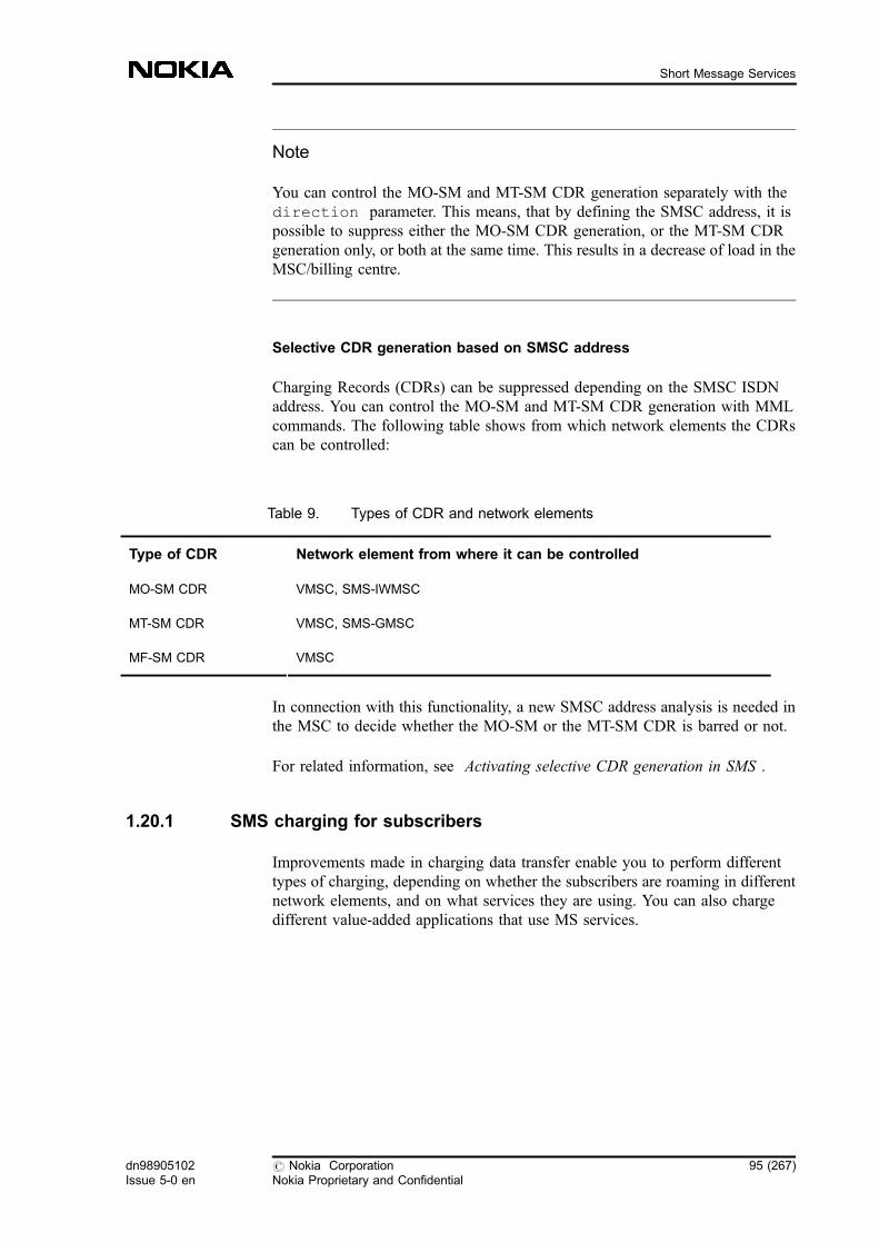
Note
You can control the MO-SM and MT-SM CDR generation separately with thedirection parameter. This means, that by defining the SMSC address, it ispossible to suppress either the MO-SM CDR generation, or the MT-SM CDRgeneration only, or both at the same time. This results in a decrease of load in theMSC/billing centre.
Selective CDR generation based on SMSC address
Charging Records (CDRs) can be suppressed depending on the SMSC ISDNaddress. You can control the MO-SM and MT-SM CDR generation with MMLcommands. The following table shows from which network elements the CDRscan be controlled:
Table 9. Types of CDR and network elements
Type of CDR Network element from where it can be controlled
MO-SM CDR VMSC, SMS-IWMSC
MT-SM CDR VMSC, SMS-GMSC
MF-SM CDR VMSC
In connection with this functionality, a new SMSC address analysis is needed inthe MSC to decide whether the MO-SM or the MT-SM CDR is barred or not.
For related information, see Activating selective CDR generation in SMS .
1.20.1 SMS charging for subscribers
Improvements made in charging data transfer enable you to perform differenttypes of charging, depending on whether the subscribers are roaming in differentnetwork elements, and on what services they are using. You can also chargedifferent value-added applications that use MS services.
dn98905102Issue 5-0 en
# Nokia CorporationNokia Proprietary and Confidential
95 (267)
Short Message Services
SMS charging for mobile subscribers
If feature 327 is in use in your exchange, the charging implications include anoption to make detail record of MO-SMs (both in the VMSC and the SMS-IWMSC and MT-SMs (both in the SMS-GMSC and the VMSC). For moreinformation, see the feature description of Feature 327: Short Message Services .
Both MT-SMs and MO-SMs can be charged in the VMSC , SMS-GMSC andSMS-IWMSC , and the traffic administration can collect SMS data in all of them.For more information, see Feature 619: Short Message Service Enhancements .
You can choose how to perform SMS charging by following steps given below.
. Create a CDR for all normal SMs which are sent (excluding SMS-COMMAND and STATUS-REPORT).
. Create a CDR for only those normal SMs which were sent successfully(excluding SMS-COMMAND and STATUS-REPORT).
. Create a CDR for all SMS-COMMAND SMs which are sent.
. Create a CDR only for SMS-COMMAND SMs which were sentsuccessfully.
. Create a CDR for all SMS-STATUS-REPORT SMs which are sent.
. Create a CDR only for SMS-STATUS-REPORT SMs which were sentsuccessfully.
Furthermore, if charging is concentrated in SMS-IWMSC/SMS-GMSC, you canset the CDR to be created in the VMSC for roaming subscribers only.
. Create a CDR only for roaming subscribers for all SMs which are sent(including SMS-COMMAND and STATUS-REPORT).
. Create a CDR only for roaming subscribers for only those normal SMswhich were sent successfully (including SMS-COMMAND and STATUS-REPORT).
SMS charging for roaming subscribers
Roaming subscribers cannot be charged according to their location unlessinformation is transferred on subscriber A's location (VMSC address) in the MT-SM CDR . In the SMS-IWMSC, subscriber A's VMSC address is transferred tothe SMSC which further transfers it to a SMS-GMSC, where the address is addedto the MT-SM CDR. The billing centre can now analyse at least the networkswhere the subscriber is roaming, or, if both are located in their own networks, the
96 (267) # Nokia CorporationNokia Proprietary and Confidential
dn98905102Issue 5-0 en
SMS Guide

MSCs where the subscribers are located. An analysis of the MO-SM CDR is nolonger needed. Adding subscriber A's VMSC field in the MT-SM CDR allowsdetermining extra charges for an MO-SM sent from a subscriber roaming outsidethe subscriber's own network.
Note that the availability of a VMSC address depends on the networkconfiguration. If signalling point addressing is used on the SCCP level, theVMSC address cannot be obtained. On the other hand, cases like this are likely tohappen only within one's own network. Inter-network addressing is usually basedon global title addresses, and VMSC addresses are available.
SMS charging based on subscriber's IMSI
Charging can generally be based on IMSI rather than MSISDN address. In MT-SMS a subscriber's IMSI is available both in the SMS-GMSC and the VMSC . InMO-SMS in case of MAP version 2 , IMSI is not available in the SMS-IWMSC.It is possible for SMS-IWMSC to fetch the subscriber's IMSI from the HLR byusing MAP phase 2 operation send_IMSI if you have feature 619 in use. In caseof MAP version 3 the VMSC sends the IMSI to the SMS-IWMSC through theMO-Forward-SM operation.
Feature 619 makes it possible for you to control whether IMSI is sent to theSMSC for charging purposes. You have to set theCHARGING_BASED_ON_IMSI PRFILE parameter on to determine whetherthe IMSI of a subscriber is used for charging purposes within the SMS.
You can find a list of parameters in SMS-related general parameter file(PRFILE/FIFILE) parameters .
1.20.2 Charging of SMs generated by applications
To avoid constant changes in configurations, information on new tariff classes isadded to the MT-SM CDR . The SMSC transfers tariff classes to the SMS-GMSC, where they are added to the MT-SM CDR. The billing centre can now setthe fee by using tariff classes which have been defined only once for both theSMSC and the billing centre. New services with different origins can easily beadded because the fee can be determined on the basis of tariff class information.The following figure shows the charging of SMs generated by applications.
dn98905102Issue 5-0 en
# Nokia CorporationNokia Proprietary and Confidential
97 (267)
Short Message Services

Figure 38. Charging of SMs generated by applications
The tariff class field makes it easier to add new service applications withouthaving to define them in the billing system.
1.20.3 Charging of SMs to service applications
The MO-SM routing analysis in the MSC is useful also for charging purposes.The MO-SMs to different applications can have different prices, for example, anMO-SM to another MS can be charged quite low, while an MO-SM to a telefaxaddress can be much more expensive. The tariff class is included in the MO-SMCDR .
The use of prefixes for charging can be useful, for example, in case of shortmessages sent to Wireless Applications Protocol (WAP) servers. In this case,charging can be determined on the basis of the prefix associated with the relevantWAP application.
If no tariff class has been defined for a certain PID /prefix, it is not sent to thecharging applications.
Neither the PID nor the prefix are sent to charging applications. SMs toapplications are charged according to the MO-SM CDRs, and SMs to MSs arecharged according to the MT-SM CDRs.
HLR
SMS-GMSC VMSC
SMSC
ForwardSM
4
Tariff Class
SRI
MT-SMSMT-SMS
Tariff Class -> MT-CDR
31
2
Application
98 (267) # Nokia CorporationNokia Proprietary and Confidential
dn98905102Issue 5-0 en
SMS Guide

Note that some of the new parameters are optional, and not carried in allinterfaces. Therefore, they are not necessarily available for charging andstatistical purposes in every MSC/VLR. To be able to charge subscribers sendingSMs to different services (users) from different locations, note the followingsuggestions on the configuration:
1. A PID and/or a prefix analysis with a tariff class is created for everyapplication service for an MO-SM. Charging of these SMs is handled fromthe SMS-IWMSC/VMSC CDRs.
2. Separate charging can be created for SMS commands by transferring theSM type 'command' to the charging application in the SMS-IWMSC/VMSC.
3. MT-SMs generated by an application service are charged from the SMS-GMSC if a tariff class has been received from the SMSC.
4. Normal MS-to-MS SMs are charged from the SMS-GMSC of the MT-CDR. The fee can be determined by comparing subscriber A's VMSCaddress with the SMS-GMSC address, and/or by comparing subscriber B'sVMSC address with the SMS-GMSC address.
1.20.4 Charging of CAMEL SMs
The CAMEL service at the SCP can create special CDRs for SMs containing freeformat data by FCI operation. These can be used for billing the subscriber by theservice based at the billing center.
In case of a prepaid service, the SCP manages the billing, and the call time of thesubscriber is restricted in the SSP according the instructions of the SCP.
When the gsmSCF modifies the subscriber number, the modified number is usedin CDRs.
For background information see CAMEL short message service .
CDR generation in CAMEL SMS
SMMO CDR is generated for originated SM. In CAMEL 2, IN4 CDR is usedalready in call related cases. In CAMEL 3, the maximum length of FCI dataraises from the current 40 octets to 160 octets, and the new IN5 CDR isintroduced. New CDR Fields IN5 CDR includes the same fields as IN4 CDR.
Fields to which the information is not available are filled with FF's(CAMEL_CALL_REFERENCE, CAMEL_EXCHANGE_ID,CAMEL_EXCHANGE_ID_TON AND PARTY_TO_CHARGE).
dn98905102Issue 5-0 en
# Nokia CorporationNokia Proprietary and Confidential
99 (267)
Short Message Services
DEFAULT_SMS_HANDLING and CAMEL_SMS_MODIFICATION fields areadded to SMMO CDR.
Default SMS Handling parameter indicates what happened, if, for example, thegsmSCF was not available and whether CAMEL encountered default SMShandling. This flag is set ON when gsmSCF connection fails, but the event is notcleared. CAMEL SMS Modification indicates the parameters that CAMEL hasmodified. These are the following:
. calling number
. destination subscriber number
. SMSC address
. SMS Reference number
1.20.5 MO-SM fraud prevention
You can allow real charging information to be forwarded from the SMSapplication to charging application with the CHAR_WITHOUT_ACK_TO_MSPRFILE parameter even if a release message has been received from the MSbefore the acknowledgement from the SMSC. The release message can bereceived if the subscriber, for example, removes the battery from the MS (or insome mobiles, pushes the 'red button') right after sending an MO-SM.
If the parameter has a TRUE value, the SMS application ignores the releasemessage from the MS and waits for the real result of the MO-SM, which is senttowards the charging application.
In case of a FALSE value, the SMS application informs the charging applicationabout the MO-SM being unsuccessful even if it is delivered successfully to theSMSC.
You can find a list of parameters in section SMS-related general parameter file(PRFILE/FIFILE) parameters .
1.20.6 Mobile number portability solutions for MO-SM charging
If Mobile Number Portability (MNP ) is used in the network, the B-MSISDNnumber does not specify the destination network of an SM and therefore notenough for charging purposes. If you want to offer different prices based on themobile service provider of the called party in case of MNP, B-IMSI number needsto be put into the SM-MO CDR, since only this number can identify the networkof the B subscriber.
100 (267) # Nokia CorporationNokia Proprietary and Confidential
dn98905102Issue 5-0 en
SMS Guide
If you have Feature 1641: B-IMSI retrieval in MO side for MNP in use in yournetwork, you can charge differently the MO-SMs which are sent to home or todifferent networks. For this, the SMS application (which runs in MO-IWMSC)has to initiate a SEND_IMSI MAP operation to retrieve the B-subscriber's IMSInumber because of the MNP service.
B-IMSI is written into the SMMO_CDR as follows:
1. When a SUBMIT MO-SM arrives to the IWMSC and the feature is active,SMS application checks the SMS routing analysis to decide if the MO-SMis application terminated SM, or MS to MS SM.
2. If the MO-SM is not application terminated SM, the SMS applicationinitiates SEND_IMSI operation with the B-MSISDN number to get theIMSI number of subscriber B through the SRRi towards the HLR.
For more information, see the feature description of Feature 1641: B-IMSIRetrieval in MO side for MNP.
3. When the response arrives from HLR, the received B-IMSI is written intothe SMMO-CDR.
When MAP version 2 is in use between the network elements, then A-IMSI is nottransferred from MO-VMSC to MO-IWMSC. So double SEND_IMSI operationsmust be done in MO-IWMSC to gain both IMSIs for charging purposes.
Note
The functionality is implemented in MO_IWMSC.
1.21 SMS-related statistics
The following statistical reports and functions provide SMS-related statisticalinformation:
. SMS measurement
. service measurement
. MSC SMS observation report
. MAP measurement
dn98905102Issue 5-0 en
# Nokia CorporationNokia Proprietary and Confidential
101 (267)
Short Message Services

. Rejected Calls Observation Report
. Traffica
SCP visit preventions are shown in IN service gapping measurement. SCP visitscan be seen in INAP measurement as protocol level events.
Detailed information on statistics on SMS can be found in NSS Statistics , and inNSS Statistics, Reports (ASCII, Binary) .
1.21.1 SMS statistics in the MSC
SMS measurement
If you have Feature 1165: Short Message Services, GSM Phase 2+ Enhancementsin use in your network, you can use SMS measurement.
There are statistical counters for the number of mobile-terminating shortmessages (including welcome MT-SMs) coming from a certain SMSC and for thenumber of MO-SMs going to a certain SMSC.
This can be used, for example, for filtering the misuse of SMs by easilyrecognizing SMSCs frequently used by the subscribers. You can check whether,for example, a foreign PLMN's SMSC is frequently used by roaming subscribersor it is misused by their own subscribers. In the latter case you can define theappropriate barring to avoid bulk short messages.
You can use this functionality if you have the SMSC connected through MAP (inthe VMSC function), or if you have the SMSC connected through SMRSE (bothwith X.25 and TCP/IP).
This measurement counts the successful and unsuccessful MO-SMs andsuccessful and unsuccessful MT-SMs according to SMSC address. In the MT-SMunsuccessful cases it can be either temporary or permanent.
The measurements include welcome MT-SMs. Welcome MO-SMs are separatelycounted. However, welcome MT-SMs are included in the MT-SM counters,because they are seen by SMSC as ordinary MT-SMs.
Note
The measurement of the Welcome SMs means the Welcome MO trigger SMcount. For more information on welcome MO-SMs and welcome MT-SMs, seeWelcome SM to the roamer .
102 (267) # Nokia CorporationNokia Proprietary and Confidential
dn98905102Issue 5-0 en
SMS Guide
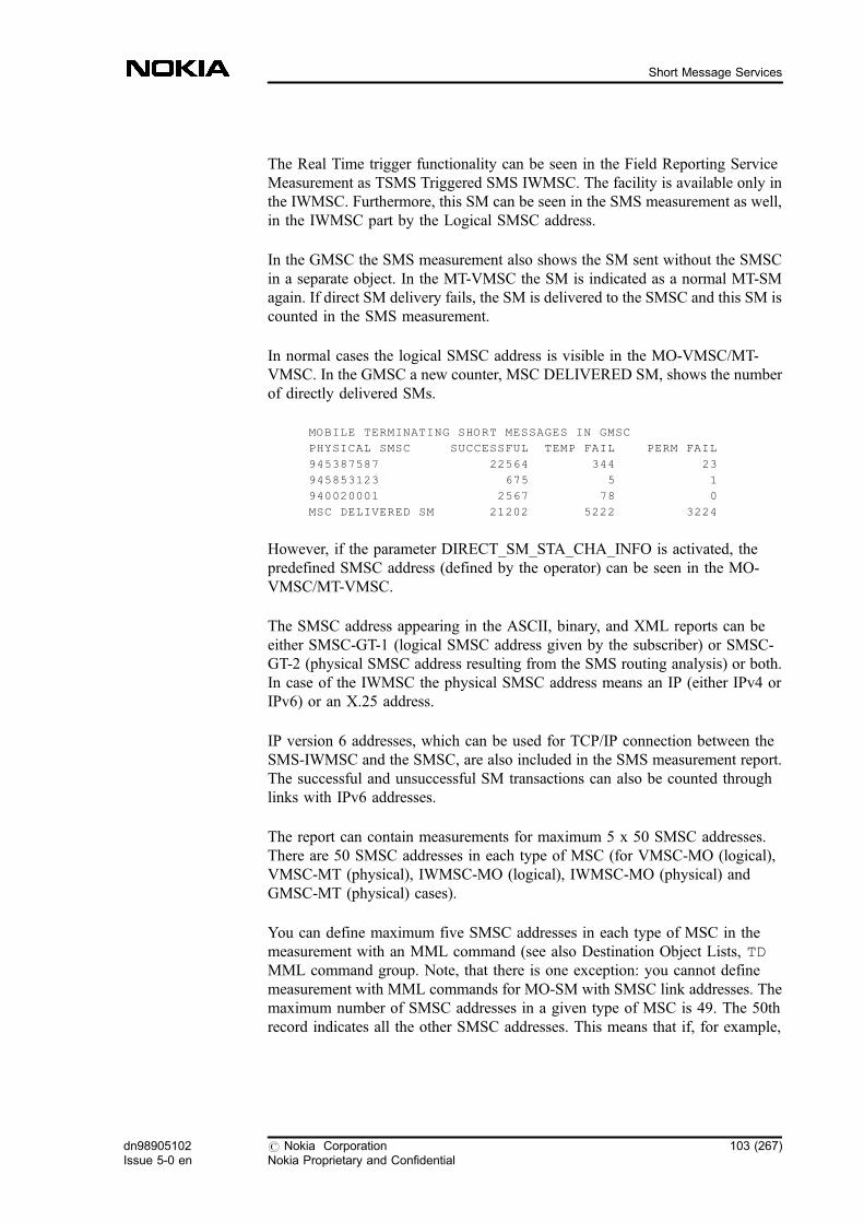
The Real Time trigger functionality can be seen in the Field Reporting ServiceMeasurement as TSMS Triggered SMS IWMSC. The facility is available only inthe IWMSC. Furthermore, this SM can be seen in the SMS measurement as well,in the IWMSC part by the Logical SMSC address.
In the GMSC the SMS measurement also shows the SM sent without the SMSCin a separate object. In the MT-VMSC the SM is indicated as a normal MT-SMagain. If direct SM delivery fails, the SM is delivered to the SMSC and this SM iscounted in the SMS measurement.
In normal cases the logical SMSC address is visible in the MO-VMSC/MT-VMSC. In the GMSC a new counter, MSC DELIVERED SM, shows the numberof directly delivered SMs.
MOBILE TERMINATING SHORT MESSAGES IN GMSC
PHYSICAL SMSC SUCCESSFUL TEMP FAIL PERM FAIL
945387587 22564 344 23
945853123 675 5 1
940020001 2567 78 0
MSC DELIVERED SM 21202 5222 3224
However, if the parameter DIRECT_SM_STA_CHA_INFO is activated, thepredefined SMSC address (defined by the operator) can be seen in the MO-VMSC/MT-VMSC.
The SMSC address appearing in the ASCII, binary, and XML reports can beeither SMSC-GT-1 (logical SMSC address given by the subscriber) or SMSC-GT-2 (physical SMSC address resulting from the SMS routing analysis) or both.In case of the IWMSC the physical SMSC address means an IP (either IPv4 orIPv6) or an X.25 address.
IP version 6 addresses, which can be used for TCP/IP connection between theSMS-IWMSC and the SMSC, are also included in the SMS measurement report.The successful and unsuccessful SM transactions can also be counted throughlinks with IPv6 addresses.
The report can contain measurements for maximum 5 x 50 SMSC addresses.There are 50 SMSC addresses in each type of MSC (for VMSC-MO (logical),VMSC-MT (physical), IWMSC-MO (logical), IWMSC-MO (physical) andGMSC-MT (physical) cases).
You can define maximum five SMSC addresses in each type of MSC in themeasurement with an MML command (see also Destination Object Lists, TDMML command group. Note, that there is one exception: you cannot definemeasurement with MML commands for MO-SM with SMSC link addresses. Themaximum number of SMSC addresses in a given type of MSC is 49. The 50threcord indicates all the other SMSC addresses. This means that if, for example,
dn98905102Issue 5-0 en
# Nokia CorporationNokia Proprietary and Confidential
103 (267)
Short Message Services
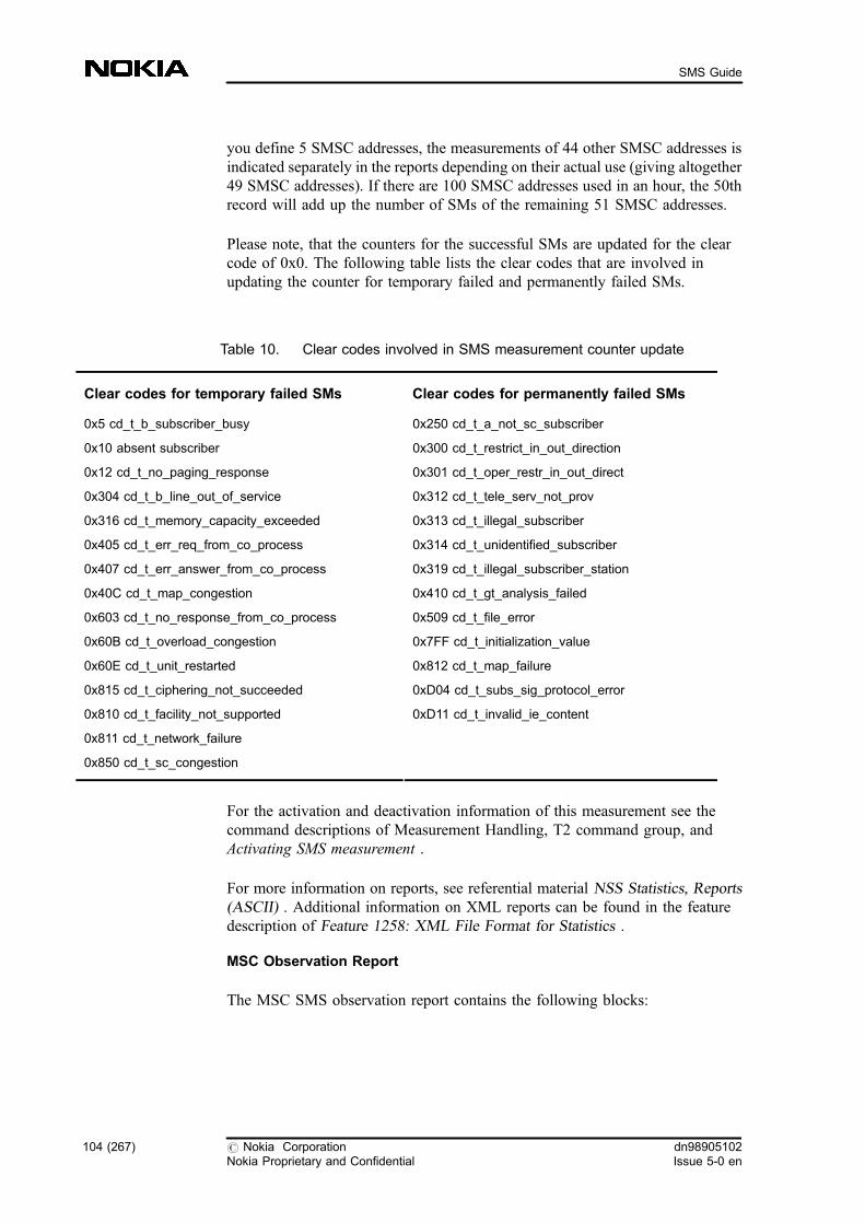
you define 5 SMSC addresses, the measurements of 44 other SMSC addresses isindicated separately in the reports depending on their actual use (giving altogether49 SMSC addresses). If there are 100 SMSC addresses used in an hour, the 50threcord will add up the number of SMs of the remaining 51 SMSC addresses.
Please note, that the counters for the successful SMs are updated for the clearcode of 0x0. The following table lists the clear codes that are involved inupdating the counter for temporary failed and permanently failed SMs.
Table 10. Clear codes involved in SMS measurement counter update
Clear codes for temporary failed SMs Clear codes for permanently failed SMs
0x5 cd_t_b_subscriber_busy
0x10 absent subscriber
0x12 cd_t_no_paging_response
0x304 cd_t_b_line_out_of_service
0x316 cd_t_memory_capacity_exceeded
0x405 cd_t_err_req_from_co_process
0x407 cd_t_err_answer_from_co_process
0x40C cd_t_map_congestion
0x603 cd_t_no_response_from_co_process
0x60B cd_t_overload_congestion
0x60E cd_t_unit_restarted
0x815 cd_t_ciphering_not_succeeded
0x810 cd_t_facility_not_supported
0x811 cd_t_network_failure
0x850 cd_t_sc_congestion
0x250 cd_t_a_not_sc_subscriber
0x300 cd_t_restrict_in_out_direction
0x301 cd_t_oper_restr_in_out_direct
0x312 cd_t_tele_serv_not_prov
0x313 cd_t_illegal_subscriber
0x314 cd_t_unidentified_subscriber
0x319 cd_t_illegal_subscriber_station
0x410 cd_t_gt_analysis_failed
0x509 cd_t_file_error
0x7FF cd_t_initialization_value
0x812 cd_t_map_failure
0xD04 cd_t_subs_sig_protocol_error
0xD11 cd_t_invalid_ie_content
For the activation and deactivation information of this measurement see thecommand descriptions of Measurement Handling, T2 command group, andActivating SMS measurement .
For more information on reports, see referential material NSS Statistics, Reports(ASCII) . Additional information on XML reports can be found in the featuredescription of Feature 1258: XML File Format for Statistics .
MSC Observation Report
The MSC SMS observation report contains the following blocks:
104 (267) # Nokia CorporationNokia Proprietary and Confidential
dn98905102Issue 5-0 en
SMS Guide

. heading information (similar in all phase 2 trace reports)
. subscriber data
. information on the short messages
Depending on the invoking event, certain report fields can be missing. This is dueto the fact that the statistical program block only fills in the fields for which therequired information is available at the moment the report is generated.
If the parameter of a specific report line does not have a value, the line is notprinted out at all.
The report contains the following new information:
. RECEIVED SMSC ADDRESS: the logical SMSC address, which is givenby the subscriber in MO-SM.
. CAMEL MODIFICATION: the called/calling number or the used SMSCaddress can be modified by the gsmSCF in case the gsmSCF has controlledSMS processing with CAP operations. If any of them is modified, it isindicated here.
. CELL BAND: the band of the cell (GSM/DCS/WCDMA)
. RNC ID: shows the identifier of the Radio Network Controller. It containsvalid information if the Radio System is UMTS.
. BSC ID: shows the identifier of the Base Station Controller. It containsvalid information if the Radio System is GSM.
. ROUTING CATEGORY: stands for the routing category of the subscriber
. ROUTING CATEGORY+: stands for the additional routing category of thesubscriber
. Two new fields for the Type Of Number (TON) of the called and dialled(address) number. These numbers can be alphanumeric.
. The radio system to/from where the subscriber sends/receives the SMS.
. MCC and MNC are added to the cell identifier
. SMS reference number (MO-SM).
Note
This report is available only if you have Feature 593: GSM Phase 2 Trace in yournetwork.
dn98905102Issue 5-0 en
# Nokia CorporationNokia Proprietary and Confidential
105 (267)
Short Message Services
For more information, see NSS Statistics, Advanced Guide and NSS Statistics,Reports (ASCII) .
MAP measurement
MAP measurements provide information about SMS usage. See instructions anddescriptions on NSS Statistics .
Rejected calls observation report
In the rejected calls observation report the services can be observed per computerunit. These reports contain the following data:
. incoming service requests
. the percentage of service requests rejected because of overload control
. the number of rejected service requests
See also referential material NSS Statistics, Reports (ASCII) .
Service measurement
Service measurement gives information on the usage of SMS. MO-SMs arefurther separated to show SMs coming from the VMSC , SMS-IWMSC, or fromthe TRANSIT MSC. MT-SMs are further separated to show SMs handled in theVMSC or SMS-GMSC.
The SMS service measurement includes field reports. The field reports containthe following measurement data:
. facility name
. usage times
The SMS-related subscriber facilities are the following:
. T21..SHORT MESSAGE MT GMSC representing the SMSC -SMS-GMSC interface in MT-SM.
. T21..SHORT MESSAGE MT VMSC representing the VMSC - MSinterface in MT-SM.
. T22..SHORT MESSAGE MO VMSC representing the MS- VMSCinterface in MO-SM.
106 (267) # Nokia CorporationNokia Proprietary and Confidential
dn98905102Issue 5-0 en
SMS Guide

. T22..SHORT MESSAGE MO IWMSC representing the SMS-IWMSC -SMSC interface in MO-SM.
. T22..SHORT MESSAGE MO TRANSIT representing the SMS-IWMSC -SMS-IWMSC interface in MO-SM.
Traffica in SMS statistics
Note
This functionality is available only if you have Feature 939: MSC Support forReal Time Reporting in your network.
Through Traffica, a detailed report is sent if the following conditions are met:
. the SM is sent form the VMSC
. the SM is forwarded
. the SM is sent from SMS-IWMSC or SMS-GMSC governed by parameter(if the VMSC is not in the same network)
For detailed information see the feature description of Feature 939: MSC Supportfor Real Time Reporting and Traffica product description.
1.21.2 SMS statistics in the HLR
Information on SMS statistics in the HLR can be obtained from HLRmeasurement and HLR observation report.
HLR measurement
Field reports contain the following measurement data:
. T21..ATTEMPTED REQUEST FOR SM ROUTING INFORMATION
. New SMS CFU counters are added to the basic services. The new countersare visible only if the feature is active.
See also referential material NSS Statistics, Reports (ASCII) .
dn98905102Issue 5-0 en
# Nokia CorporationNokia Proprietary and Confidential
107 (267)
Short Message Services
HLR observation report
The HLR subscriber observation report shows the types of the HLR operationsthat have been carried out by the subscriber under observation. The HLRobservation report is printed after the following events: SRI for SM, ready forSM, and alert service center.
The HLR subscriber observation report contains the following blocks:
. heading information (similar in all phase 2 trace reports)
. subscriber data, such as MSISDN or IMSI
. location update information
. information on the use of basic services
. information on the use of supplementary services (the type of action, thename of the service and the time)
. result of the operation that caused the report
. information on the use of short message services
. new routing category
Note
This report is available only if you have Feature 593: GSM Phase 2 Trace in yournetwork.
See also referential section NSS Statistics, HLR Observation.
For detailed information refer to feature description of Feature 593: GSM Phase 2Trace .
1.22 Network elements involved in SMS
The network elements involved in SMS are SME , SMSC , VMSC , VLR , SMS-GMSC , SMS-IWMSC , and HLR . Note that SMS-GMSC and SMS-IWMSC arefunctional roles that a single DX 200 MSC can fulfil.
SGSN is also involved if the SM delivery takes place through the GPRSnetwork.
108 (267) # Nokia CorporationNokia Proprietary and Confidential
dn98905102Issue 5-0 en
SMS Guide
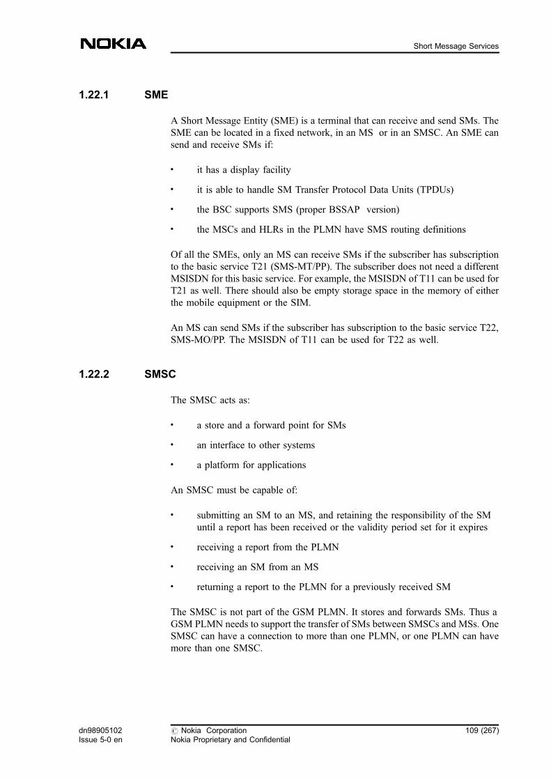
1.22.1 SME
A Short Message Entity (SME) is a terminal that can receive and send SMs. TheSME can be located in a fixed network, in an MS or in an SMSC. An SME cansend and receive SMs if:
. it has a display facility
. it is able to handle SM Transfer Protocol Data Units (TPDUs)
. the BSC supports SMS (proper BSSAP version)
. the MSCs and HLRs in the PLMN have SMS routing definitions
Of all the SMEs, only an MS can receive SMs if the subscriber has subscriptionto the basic service T21 (SMS-MT/PP). The subscriber does not need a differentMSISDN for this basic service. For example, the MSISDN of T11 can be used forT21 as well. There should also be empty storage space in the memory of eitherthe mobile equipment or the SIM.
An MS can send SMs if the subscriber has subscription to the basic service T22,SMS-MO/PP. The MSISDN of T11 can be used for T22 as well.
1.22.2 SMSC
The SMSC acts as:
. a store and a forward point for SMs
. an interface to other systems
. a platform for applications
An SMSC must be capable of:
. submitting an SM to an MS, and retaining the responsibility of the SMuntil a report has been received or the validity period set for it expires
. receiving a report from the PLMN
. receiving an SM from an MS
. returning a report to the PLMN for a previously received SM
The SMSC is not part of the GSM PLMN. It stores and forwards SMs. Thus aGSM PLMN needs to support the transfer of SMs between SMSCs and MSs. OneSMSC can have a connection to more than one PLMN, or one PLMN can havemore than one SMSC.
dn98905102Issue 5-0 en
# Nokia CorporationNokia Proprietary and Confidential
109 (267)
Short Message Services
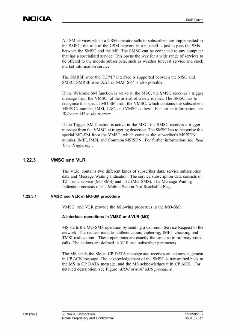
All SM services which a GSM operator sells to subscribers are implemented inthe SMSC: the role of the GSM network in a nutshell is just to pass the SMsbetween the SMSC and the MS. The SMSC can be connected to any computerthat has a specialised service. This opens the way for a wide range of services tobe offered to the mobile subscribers, such as weather forecast service and stockmarket information service.
The SMRSE over the TCP/IP interface is supported between the MSC andSMSC. SMRSE over X.25 or MAP SS7 is also possible.
If the Welcome SM function is active in the MSC, the SMSC receives a triggermessage from the VMSC at the arrival of a new roamer. The SMSC has torecognise this special MO-SM from the VMSC, which contains the subscriber'sMSISDN number, IMSI, LAC, and VMSC address. For further information, seeWelcome SM to the roamer .
If the Trigger SM function is active in the MSC, the SMSC receives a triggermessage from the VMSC at triggering detection. The SMSC has to recognise thisspecial MO-SM from the VMSC, which contains the subscriber's MSISDNnumber, IMEI, IMSI, and Common MSISDN. For further information, see RealTime Triggering .
1.22.3 VMSC and VLR
The VLR contains two different kinds of subscriber data: service subscriptiondata and Message Waiting Indication. The service subscription data consists ofT21 basic service (MT-SMS) and T22 (MO-SMS). The Message WaitingIndication consists of the Mobile Station Not Reachable Flag.
1.22.3.1 VMSC and VLR in MO-SM procedure
VMSC and VLR provide the following properties in the MO-SM:
A interface operations in VMSC and VLR (MO)
MS starts the MO-SMS operation by sending a Common Service Request to thenetwork. The request includes authentication, ciphering, IMEI checking andTMSI reallocation . These operations are exactly the same as in ordinary voicecalls. The actions are defined in VLR and subscriber parameters.
The MS sends the SM in CP DATA message and receives an acknowledgementin CP ACK message. The acknowledgement of the SMSC is transmitted back tothe MS in CP DATA message, and the MS acknowledges it in CP ACK. Fordetailed description, see Figure MO-Forward SMS procedure .
110 (267) # Nokia CorporationNokia Proprietary and Confidential
dn98905102Issue 5-0 en
SMS Guide
CP DATA is retransmitted if the RR (Radio Resource) connection is changed, orthe MS does not acknowledge it. The reason for changing the RR connection canbe a handover, for example.
The ReadyForSM operation and MWD support Memory Capacity Availablefacility. The MS can use this service to inform the SMSC that it is ready toreceive messages that it could not receive earlier because it had no free memory.
For background information, see A interface in SMS .
Figure 39. MO-SMS request
MAP interface operations
The MO-SM is transmitted further from the VMSC in MOForwardSM operation.The message contains different kinds of data, for example the addresses ofsubscriber A and the SMSC, plus the SM data. If the SMS-IWMSC knows theSMSC, it transfers the SM to it. When the SMS-IWMSC receives a response forthe SM from the SMSC, it transfers the response to the VMSC. If the VMSC andthe SMS-IWMSC are physically in one MSC then the information is transferredinternally and not on the MAP interface. For more information, see SMSprocedures performed by MAP .
- Originating (A-subscriber) Address- Destination (SMSC) Address- User Data
- Message Reference- Originating (A-subscriber)Address
- User Data
- Message Reference- Originating (A-subscriber) Address- Destination (SMSC) Address- User Data
SMRSE
SMS-IWMSC
SMSCMS
VMSCMAP
A-IF
dn98905102Issue 5-0 en
# Nokia CorporationNokia Proprietary and Confidential
111 (267)
Short Message Services

Figure 40. MO-SMS successful case (positive response)
VLR operations in SMS (MO)
The VLR receives data from the HLR, that contains information about barringsset by the subscriber, that is, interworking between subscriber-activated outgoingcall barring service, and the barrings set by you. The VLR parameters define whatoperations are performed for the subscriber during the set-up phase, that is,whether IMEI is authenticated or ciphered. The relevant barring categories arethe following:
. Operator-determined barrings:
- barring of outgoing calls
- barring of outgoing inter-zonal calls
- barring of outgoing inter-zonal calls except those directed to thehome PLMN country
- barring of outgoing international calls except those directed to thehome PLMN country and barring of outgoing inter-zonal calls
. Supplementary service barrings:
- barring of all outgoing calls
- barring of outgoing international calls
- barring of outgoing calls except those directed to the home country
Please take the following restrictions into account:
SMRSE - Message Reference- User Data
SMS-IWMSC
SMSCMS
VMSCMAP
A-IF - Message Reference- User Data
112 (267) # Nokia CorporationNokia Proprietary and Confidential
dn98905102Issue 5-0 en
SMS Guide
. The MO-SMS is provisioned for every subscriber as a basic service.Subscribers who have not been provisioned the MO-SMS in that particularVLR area are not allowed to use the service.
. If the SMSC address is unknown or outgoing calls are barred, the SMtransfer to the SMSC is not possible, and the SMS request is denied in theMSC.
Figure 41. MO-SMS unsuccessful case (negative response)
The MO-SMS is allowed at the same time when an active call and/or MT-SMSand/or USSD or SS operation to the subscriber is taking place, and vice versa.
Special conditions
. Two MO-SMS requests are not allowed simultaneously, but if there aremore messages from the same subscriber, a session between MSC and MSis not disconnected before the last message has been transferred.
. The SMSC can send diagnostic data in negative acknowledgements to theMS. The amount of data is at most the same as in MO-SMS.
For related information, see Mobile-originating short message .
1.22.3.2 VMSC and VLR in MT-SM procedure
VMSC and VLR provide the following properties in the MT-SM:
SMRSE - Message Reference- Cause (error reason)- User Data
SMS-IWMSC
SMSCMS
VMSC
- Cause (error code)- User Data
MAP
A-IF - Message Reference- Cause (error code)- User Data
dn98905102Issue 5-0 en
# Nokia CorporationNokia Proprietary and Confidential
113 (267)
Short Message Services
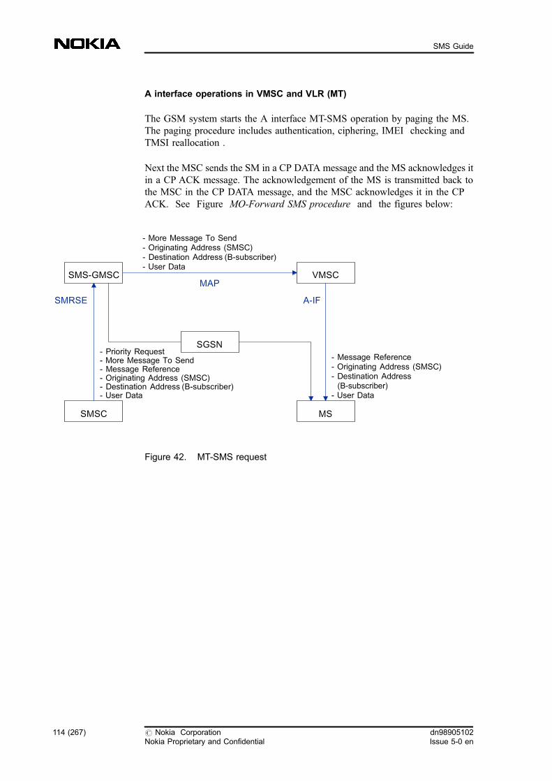
A interface operations in VMSC and VLR (MT)
The GSM system starts the A interface MT-SMS operation by paging the MS.The paging procedure includes authentication, ciphering, IMEI checking andTMSI reallocation .
Next the MSC sends the SM in a CP DATA message and the MS acknowledges itin a CP ACK message. The acknowledgement of the MS is transmitted back tothe MSC in the CP DATA message, and the MSC acknowledges it in the CPACK. See Figure MO-Forward SMS procedure and the figures below:
Figure 42. MT-SMS request
- Priority Request- More Message To Send- Message Reference- Originating Address (SMSC)- Destination Address (B-subscriber)- User Data
- Message Reference- Originating Address (SMSC)- Destination Address(B-subscriber)
- User Data
- More Message To Send- Originating Address (SMSC)- Destination Address (B-subscriber)- User Data
SMRSE A-IF
VMSC
MSSMSC
SMS-GMSCMAP
SGSN
114 (267) # Nokia CorporationNokia Proprietary and Confidential
dn98905102Issue 5-0 en
SMS Guide
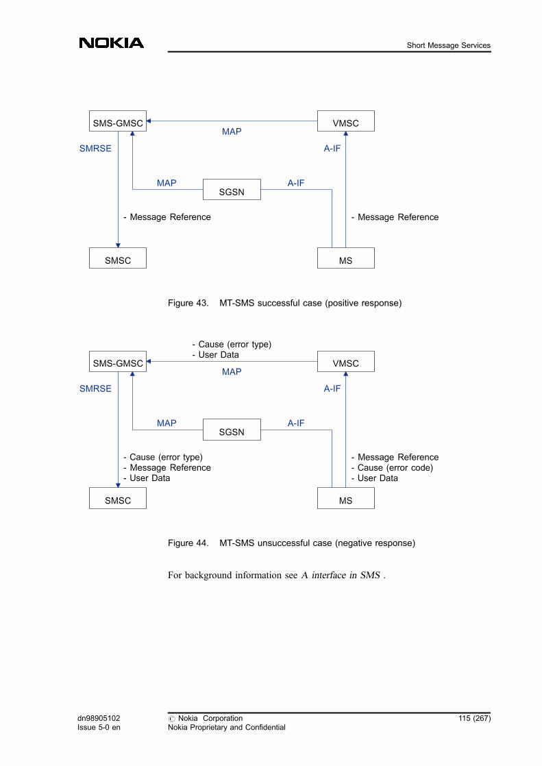
Figure 43. MT-SMS successful case (positive response)
Figure 44. MT-SMS unsuccessful case (negative response)
For background information see A interface in SMS .
- Message Reference
SMRSE A-IF
- Message Reference
MAP
VMSC
MSSMSC
SMS-GMSCMAP
A-IFSGSN
- Cause (error type)- Message Reference- User Data
SMRSE A-IF
- Message Reference- Cause (error code)- User Data
MAP
VMSC
MSSMSC
SMS-GMSC
- Cause (error type)- User Data
MAP
A-IFSGSN
dn98905102Issue 5-0 en
# Nokia CorporationNokia Proprietary and Confidential
115 (267)
Short Message Services

MAP interface operations (MT)
MT-SM is transmitted further from the SMS-GMSC in MTForwardSM operation.The message contains different kinds of data, for example, the address ofsubscriber B, and the SMSC plus the SM data. Note, that if the VMSC has adirect connection to the SMSC, the SMS-GMSC and the IWMSCfunctions asspecified later on in this section are available in the SMSC. For moreinformation on SMS procedures performed by MAP, see SMS proceduresperformed by MAP .
Special conditions
. Multiple messages during one A interface connection are possible. If theSMSC has more messages to send, or several SMSCs are sending SMs tothe same subscriber, queueing is needed. The MS is informed about this,and the connection is left open. When queueing takes place, all incomingSMs are placed in a queue in the VMSC, and they are served according toFIFO principle. All SMs are transferred to the MS in the same connectionbetween VMSC and MS.
The queue handling takes into account what kind of A interface connectionis used (fast/slow), how long the queued SM is, and how many SMs thequeue contains. Calculations based on this information define how long theSM is expected to stay in the queue, and make sure that the specifiedmaximum queuing time will not be exceeded.
. The MT-SMS is allowed when an active call and/or MO-SMS and/orUSSD or SS-operation to the subscriber is taking place, and vice versa.
. The MSC has a functionality which resends the MT-SM to the MS if ahandover or a time-out takes place: if More-Messages-to-Sendfunctionality is in use, the SMSC informs the MSC that the SMSC containsone or more SMs waiting to be delivered to the MS. The connection pathbetween the SMSC and the MS is not closed when there are more than oneSMs to the same subscriber.
. The mobile station not reachable flag is initialized in the VLR restart.
. Interworking with supplementary services, except with call barrings, is notprovided in the VMSC/VLR. For more information, see troubleshootinginstructions in Short Message Service troubleshooting .
For information on SMS resending and timer values, see MToperation in VMSC.
For further information, see Mobile-terminating short message .
116 (267) # Nokia CorporationNokia Proprietary and Confidential
dn98905102Issue 5-0 en
SMS Guide

1.22.4 SMS-IWMSC
In the case of an MO-SM, the MSC with a connection to an SMSC is calledInterworking MSC (SMS-IWMSC). The purpose of the SMS-IWMSC is toreceive MO-SMs from within the PLMN, and of transferring them from theVMSC to the SMSC. It also provides the Alert-SC function to inform the SMSCof subscribers who have become active and who have an MT-SM waiting to bedelivered to them. The SM is stored in the SMSC.
If the SMSC is connected through MAP interface, the function of the SMS-IWMSC is implemented in the SMSC.
Special conditions
. In case of an MO-SM, if the SMSC address received from the VMSC isunknown, the SM delivery is rejected.
. If the SMSC address received from the HLR is unknown, the Alert-SCrequest is cancelled. The SMSC can send diagnostic data in negativeacknowledgements to the MS. The amount of data is as long as the data inMO-SM at the most. For more information, see 3GPP TS 23.040.
1.22.5 SMS-GMSC
In the case of an MT-SM, the MSC that has direct SMSC connections is calledGateway MSC (SMS-GMSC). The SMS-GMSC is capable of receiving SMsfrom the SMSC and interrogating the HLR for routing and SMS information withSendRoutingInfoForSM operation. The purpose of the SMS-GMSC is to transferan MT-SM from the SMSC to an appropriate VMSC /SGSN . In case of anunsuccessful SM delivery attempt, it uses the ReportSM-DeliveryStatus operationto set the MNRF /MNRG or MCEF flag, and to put the SMSC address to theMWD list of the subscriber. See Figure MT-SMS procedure .
In case of MAP interface, the function of the SMS-GMSC is implemented in theSMSC.
Special conditions
In case the absent subscriber error code is received from the HLR, informationindicating whether the SMSC address is included in the MWD list or not, is sentto the SMSC. If an error code indicating an absent or unidentified subscriber isreceived from the VMSC, the SMS-GMSC initiates ReportSM-DeliveryStatusoperation towards the HLR, provided that the SMSC address was not previouslyincluded in the MWD list. The subscriber address, which is used for alertingwhen the subscriber becomes available, is also returned.
dn98905102Issue 5-0 en
# Nokia CorporationNokia Proprietary and Confidential
117 (267)
Short Message Services

If a subscriber has MWD in HLR, an SM with priority indication can be sent,causing the HLR to return routing information. If the SM transfer succeeds, theSMS-GMSC informs the HLR about a successful transfer, which in turn starts theAlert-SC operation. An MS can send diagnostic data in negativeacknowledgements to the SMSC. The amount of data is as long as the data in theMT-SM at the most.
Two MT-SMS requests are not allowed simultaneously, but if there are moremessages for the same subscriber, the session between the SMSC and the MS isnot disconnected before the last message is transferred. This is indicated with theMoreMessagesToSend parameter in the MT-SM.
1.22.6 HLR
Both MO-SMS and MT-SMS are implemented as basic services in the HLR. ForSMS, it is possible to obtain routing information for an incoming SM.
The implementation of SMS in the HLR can be divided into the storage of SMS-related data in the HLR, the operations for the SMS service, and the managementof SMS functions. Subscriber management functions provide the management ofSMS: they allow the addition, deletion, and modification of subscribers' basicservices. For detailed instructions, see Managing SMS subscriber-specific data .
SMS-related data in HLR
The HLR provides two information elements for the SMS function that form anintegral part of the HLR and its file system. These are the following:
. SM services (mobile-terminating and mobile-originating are considered asseparate services)
. subscriber-specific SMSC address lists for each subscriber for whom theSMS services have been allocated
The HLR provides these functions together with MAP.
There are three different kinds of procedure concerning the SM operation:
118 (267) # Nokia CorporationNokia Proprietary and Confidential
dn98905102Issue 5-0 en
SMS Guide
1. When the HLR receives a ReportSMDeliveryStatus message, it sets theaddress of the SMSC into the MWD list and returns a positiveacknowledgement to the element that requested it. If the address alreadyexists, the HLR sends a positive acknowledgement.
2. When the MWD list contains SMSCs, it means that the subscriber isunreachable and all inquiries about the SM routing are rejected. The onlyexception is the priority SM. In this case, routing an SM to a subscriber isattempted even if MWD contains addresses.
3. If no priority is used and the MWD contains addresses, a negativeacknowledgement is sent with the error code 'absent subscriber' to theSMSC, and the SMSC address is stored in the MWD.
If the SMS services (both MO/PP and MT/PP) are not defined for a subscriber asbasic services, all SMS-related operations are rejected for that subscriber, and theSM services are not available for him in the network.
The incoming call barring supplementary services and also operator-determinedbarring can be used with the MT-SMS. The HLR provides the supplementaryservice support. For the SMSC address lists only one address list space isprovided, and the subscribers' lists are implemented by relational indexing insidethis common pool. There is no inherent limit to the length of a subscriber's SMSClist.
HLR operations for SMS service
The following MAP-level operations implemented in the HLR are supported:
1. SendRoutingInfoForSM
This operation allows MT-SMs to be routed to mobile subscriberseverywhere in the GSM networks using VMSC address.
2. ReportSM-DeliveryStatus
In the case of a non-deliverable SM, the SMS-GMSC informs the HLR,which stores the address of delivered SMSC for subsequent use. The HLRis also notified if a transfer succeeds when an MWD was set.
3. ReadyForSM
When the subscriber has again become active, or has free memory capacityagain, the VLR sends this operation to the HLR.
4. InformServiceCentre
This operation informs the SMSC which ISDN number is used forindicating that an MS can receive SMs.
dn98905102Issue 5-0 en
# Nokia CorporationNokia Proprietary and Confidential
119 (267)
Short Message Services
5. AlertServiceCentre
When a subscriber has again become active, the HLR informs all SMSCsthat have undeliverable SMs waiting for him.
The data in the HLR can be further divided into service subscription data andmessage waiting data.
Service subscription data consists of the following two services:
. T21 basic service (MT-SMS)
. T22 basic service (MO-SMS)
Message Waiting Indication consists of:
. Message Waiting Data List (SMSC addresses)
. Mobile Station Not Reachable Flag (MNRF)
. Mobile Station Not Reachable for GRPS Flag (MNRG)
. Mobile Station Not Reachable Reason (MNRR)
. Mobile Station Memory Capacity Exceeded Flag
For more information, see SMS information elements .
When the system attempts to send an SM to a subscriber, the HLR receives therouting inquiry for the SM. If the subscriber does not have the T21 basic serviceprovisioned, the HLR rejects the operation.
SMS Forwarding functionality is implemented in the HLR.
1.22.7 Traffica
The information about the Welcome SM is sent to Traffica, which is a real timemonitoring tool.
For background information, see Welcome SM to the roamer.
For statistics-related information on Traffica see Traffica in SMS Statistics .
120 (267) # Nokia CorporationNokia Proprietary and Confidential
dn98905102Issue 5-0 en
SMS Guide
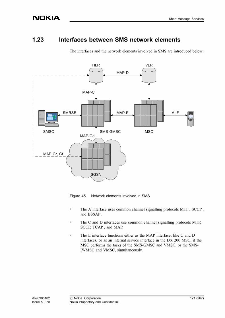
1.23 Interfaces between SMS network elements
The interfaces and the network elements involved in SMS are introduced below:
Figure 45. Network elements involved in SMS
. The A interface uses common channel signalling protocols MTP , SCCP ,and BSSAP .
. The C and D interfaces use common channel signalling protocols MTP,SCCP, TCAP , and MAP.
. The E interface functions either as the MAP interface, like C and Dinterfaces, or as an internal service interface in the DX 200 MSC, if theMSC performs the tasks of the SMS-GMSC and VMSC, or the SMS-IWMSC and VMSC, simultaneously.
SMS-GMSC MSC
HLR VLR
SMSC
SGSN
MAP-C
MAP-D
MAP-E A-IFSMRSE
MAP-Gd
MAP Gr, Gf
dn98905102Issue 5-0 en
# Nokia CorporationNokia Proprietary and Confidential
121 (267)
Short Message Services
. The P interface functions as the X.25 interface. The following OSIprotocols are used in this interface: OSI-layers 4-6, ROSE, ACSE andSMRSE (Short Message Relay Service Element). The SMRSE is specifiedin ETSI Specification 03.47.
. There is also a Nokia-specific TCP/IP interface for P interface. For moreinformation, see Feature 931: Short Message Service transfer over TCP/IP .
1.23.1 A interface in SMS
Short Messaging uses only the following signalling channels:
. SDCCH
A Stand Alone Dedicated Control Channel is a two-way signalling channelnormally used for call establishment and location updates. When there isno voice call active, SDCCH channels are used for short messages. Onetraffic channel (TCH) can be combined into 8 SDCCHs.
. SACCH
If a voice call is active, a Slow Associated Control Channel is used forshort messaging, which means that messages can be sent and received evenduring a call. Each SDCCH or traffic channel is accompanied by a two-way SACCH.
When there is no active call, USSD and SMS use the same SDCCH signallingchannel. During a call, USSD uses FACCH channel, when SMS uses SACCH.With SACCH the sending of the SM takes about three times longer than withSDCCH. The transfer of USSD with FACCH is 5-7 times faster than SMS withSACCH. USSD and SMS are possible simultaneously, even during a call. Formore information on the A interface, see 3GPP TS 24.008 and 24.011.
For more information, see A interface operations in VMSC and VLR (MO) , andA interface operations in VMSC and VLR (MT) .
1.23.2 SMRSE in SMS
The exchange of messages between the MSC and the SMSC is based on ShortMessage Relay Service Element (SMRSE) interface defined in Technical report03.47. The SMRSE needs a reliable transport service to exchange messages.There are two alternatives: X.25 and TCP/IP connection. Both interface optionscan co-exist in the MSC site. Each SMSC can support either the TCP/IP or X.25connection.
122 (267) # Nokia CorporationNokia Proprietary and Confidential
dn98905102Issue 5-0 en
SMS Guide
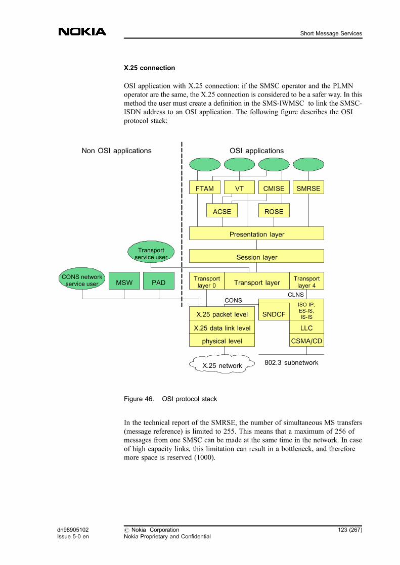
X.25 connection
OSI application with X.25 connection: if the SMSC operator and the PLMNoperator are the same, the X.25 connection is considered to be a safer way. In thismethod the user must create a definition in the SMS-IWMSC to link the SMSC-ISDN address to an OSI application. The following figure describes the OSIprotocol stack:
Figure 46. OSI protocol stack
In the technical report of the SMRSE, the number of simultaneous MS transfers(message reference) is limited to 255. This means that a maximum of 256 ofmessages from one SMSC can be made at the same time in the network. In caseof high capacity links, this limitation can result in a bottleneck, and thereforemore space is reserved (1000).
ISO IP,ES-IS,IS-IS
CONSCLNS
Presentation layer
ROSE
FTAM VT CMISE
Session layer
Transport layerTransportlayer 4
Transportlayer 0PAD
Non OSI applications OSI applications
SMRSE
802.3 subnetworkX.25 network
MSWCONS networkservice user
Transportservice user
X.25 packet level
X.25 data link level
physical level CSMA/CD
LLC
SNDCF
ACSE
dn98905102Issue 5-0 en
# Nokia CorporationNokia Proprietary and Confidential
123 (267)
Short Message Services
If feature 619 is in use in your exchange, you can control the maximum value ofmessage references towards SMSC (MO-SMS).
TCP/IP connection
The full seven layered OSI stack of the X.25 connection is quite heavy fortransferring relatively simple data, such as SMs, and therefore it unnecessarilyloads the physical line transfer capacity and the processing capacity of thecomputer unit that controls the line. Therefore, if Feature 931: Short MessageService Transfer over TCP/IP is in use in your network, it can increase theperformance of the transmission between the MSC and the Nokia SMSCconveying SM traffic.
The purpose of TCP/IP is to provide a fast and efficient way of transferring SMsbetween MSCs and SMSCs. It implements the functionality defined for SMRSE.There are also some Nokia-specific features, for example, additional parameters,which have to be implemented. Altogether this feature provides all the tasks andfeatures of the previous solution, but in a more efficient way. TCP/IP reduces theamount of protocol layers and therefore the time needed for processing amessage.
The interface improves the SM transfer capacity considerably. Because of thehigh capacity, the number of messages that can be handled simultaneouslyincreases significantly. Consequently, there must be a way to restrict the traffic.The amount of the messages can be tuned up to the optimal for the systemconfiguration used. This prevents the SM transfer system from producing toohigh a load in the rest of the system.
The following figure describe the protocol stack for SMS with TCP/IP.
124 (267) # Nokia CorporationNokia Proprietary and Confidential
dn98905102Issue 5-0 en
SMS Guide

Figure 47. Protocol stack for SMS with TCP/IP
Both IPv4 and IPv6 are supported.
For a more detailed information refer to the feature descriptions of Feature 931:Short Message Service Transfer over TCP/IP .
For related information, see Comparison of SMS functionalities in case ofSMRSE over X.25 or TCP/IP and SS7 MAP SMSC .
1.23.3 MAP in SMS
MAP is an interface that follows the GSM specification. See the figure below:
SS7Ethernet
SMS-IWMSC/GMSC
TCP/IP stack
Link Layer -802.3
IP
TCP
SMRSE SMS Appl.
MTP
SCCP
TCAP
MAP
SMSC
SMRSE
TCP/IPProtocolStack
dn98905102Issue 5-0 en
# Nokia CorporationNokia Proprietary and Confidential
125 (267)
Short Message Services
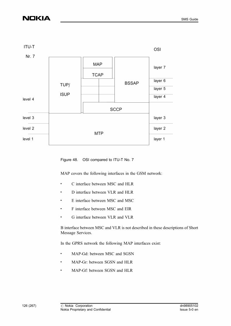
Figure 48. OSI compared to ITU-T No. 7
MAP covers the following interfaces in the GSM network:
. C interface between MSC and HLR
. D interface between VLR and HLR
. E interface between MSC and MSC
. F interface between MSC and EIR
. G interface between VLR and VLR
B interface between MSC and VLR is not described in these descriptions of ShortMessage Services.
In the GPRS network the following MAP interfaces exist:
. MAP-Gd: between MSC and SGSN
. MAP-Gr: between SGSN and HLR
. MAP-Gf: between SGSN and HLR
MTP
SCCP
BSSAPTUP/
ISUP
OSIITU-T
Nr. 7
level 1
level 3
level 2
level 4
layer 1
layer 2
layer 3
layer 4
layer 5
layer 6
layer 7
TCAP
MAP
126 (267) # Nokia CorporationNokia Proprietary and Confidential
dn98905102Issue 5-0 en
SMS Guide
MAP provides the following SMS procedures for its users:
. MOForwardSM: between VMSC and SMS-IWMSC or between VMSCand SMSC
. MTForwardSM: between SMS-GMSC and VMSC or between SMSC andVMSC
. SendRoutingInfoForSM: between SMS-GMSC and HLR or betweenSMSC and HLR
. ReportSM-DeliveryStatus: between SMS-GMSC and HLR or betweenSMSC and HLR
. InformServiceCentre: between HLR and SMS-GMSC or between HLRand SMSC
. ReadyForSM: between VLR and HLR
. AlertServiceCentre: between HLR and SMS-GMSC or between HLR andSMSC
. SendIMSI: between SMS-IWMSC and HLR or between SMSC and HLR
One MAP procedure can be executed during one TCAP dialogue. See SMSprocedures performed by MAP for detailed explanations of the procedures.
The alternative to OSI for implementing SMSC and SMS-GMSC or SMS-IWMSC connection is the MAP interface with CCS7 link. In this case the SMSCis integrated to the CCS7 network, and the functionalities of SMS-GMSC andSMS-IWMSC are combined to the SMSC. Routing definitions are easier thanwith the X.25 connection. Every MSC and HLR can send SMs directly to theSMSC, as well as receive them directly from there.
MAP version 3 is supported if you have Feature 1043: Short Message ServicesGSM Phase 2+ in the network. This MAP version includes the parametersnecessary for SMS over GPRS . For more information refer to featuredescriptions of Feature 1043: Short Message Services GSM Phase 2+ andFeature 857: Support of General Packet Radio Service (GPRS) .
MAP-Gd
MAP-Gd is the interface between the MSC and the Serving GPRS Support Node(SGSN). The SMS-related MAP version 3 makes the usage of Feature 857:Support of General Packet Radio Service (GPRS ) possible. The following figureshows the SMS architecture with SGSN.
dn98905102Issue 5-0 en
# Nokia CorporationNokia Proprietary and Confidential
127 (267)
Short Message Services
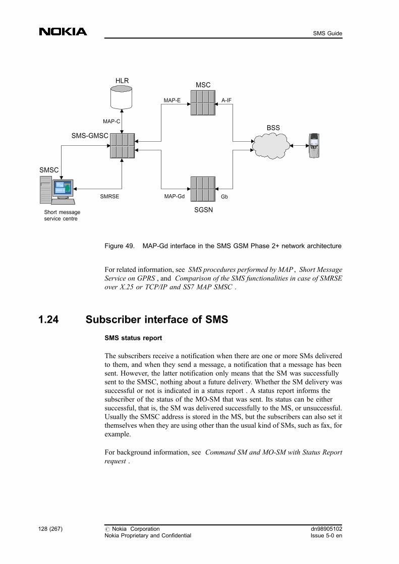
Figure 49. MAP-Gd interface in the SMS GSM Phase 2+ network architecture
For related information, see SMS procedures performed by MAP , Short MessageService on GPRS , and Comparison of the SMS functionalities in case of SMRSEover X.25 or TCP/IP and SS7 MAP SMSC .
1.24 Subscriber interface of SMS
SMS status report
The subscribers receive a notification when there are one or more SMs deliveredto them, and when they send a message, a notification that a message has beensent. However, the latter notification only means that the SM was successfullysent to the SMSC, nothing about a future delivery. Whether the SM delivery wassuccessful or not is indicated in a status report . A status report informs thesubscriber of the status of the MO-SM that was sent. Its status can be eithersuccessful, that is, the SM was delivered successfully to the MS, or unsuccessful.Usually the SMSC address is stored in the MS, but the subscribers can also set itthemselves when they are using other than the usual kind of SMs, such as fax, forexample.
For background information, see Command SM and MO-SM with Status Reportrequest .
SMSC
HLRMSC
MAP-C
MAP-E A-IF
SMRSE
Short messageservice centre
SGSN
MAP-Gd
SMS-GMSCBSS
Gb
128 (267) # Nokia CorporationNokia Proprietary and Confidential
dn98905102Issue 5-0 en
SMS Guide

Prevention of SMS
If the subscribers want to bar incoming or outgoing SMs or both, they, in general,must bar all incoming or outgoing calls, or both. They can bar all incoming/outgoing SMs if the menu of their MS supports it. Likewise, if they bar allincoming and/or outgoing calls, this automatically means that SMs are alsobarred.
For background information, see Barring SMS in the MSC .
User Data in MT/MO-SMS acknowledgement message
Since the UserData in the acknowledgement messages is available, SIM datadownload becomes possible. This can be useful in cases when, for example, theuser has a prepaid SIM card because the data download is possible by the SMS.
Alphanumeric addressing of SMS-related applications
The subscriber has the benefit of easy addressing of SMS-related applications asthis feature supports alphanumeric addresses for the destinations of shortmessages.
The alphabetical address is carried in the MO-SM. The characters are representedby a hexadecimal number in an 7�bit octet. For example, the character 'J' isrepresented as 0x4A (01001010 in binary format). The upper 4 bits (from themost significant bit (MSB)) contains the first digit of the hexadecimal numberand the below 4 bits (from the least significant bit (LSB)) contains the seconddigit thereof.
Our example (the letter 'J') can be, thus, represented as below:
Figure 50. An example for hexadecimal numbers used in alphanumericaddressing
Accordingly, if the subscriber sends a short message to the address 'JOKEBOX',the address in hexadecimal format is 4A 4F 4B 45 42 4F 58 (see below).
MSB LSB
1 0 0 1 0 1 0
"4" "A"
dn98905102Issue 5-0 en
# Nokia CorporationNokia Proprietary and Confidential
129 (267)
Short Message Services
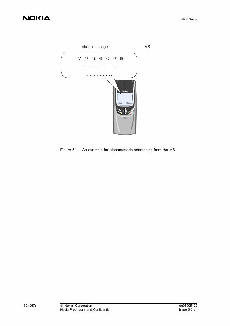
Figure 51. An example for alphanumeric addressing from the MS
4A 4F 4B 45 42 4F 58
- - - - - - - - - - - -
- - - - - - - - -
short message MS
130 (267) # Nokia CorporationNokia Proprietary and Confidential
dn98905102Issue 5-0 en
SMS Guide

2 Configuring network elements for SMS
The SMS-PP is available for use after the SW installation, the creation of GlobalTitle analyses, the SMSC address analysis, and the connection between the SMS-IWMSC/SMS-GMSC and the SMSC. For more information, see the Featuredescriptions of Feature 327: Short Message Services and SMSC Guide toCommissioning for HP 9000/700 and 9000/800 and the instructions on OSI.
The interfaces and the network elements involved in SMS-PP are shown in thefollowing figures.
Figure 52. MO-SM interfaces
In the examples below the network element addresses are:
VMSC address: 4434050VLR address: 4434051IWMSC address: 443406SMSC address: 44340600001
MS BSS VMSC SMS-GMSC
SMSCA E P
B
VLR
dn98905102Issue 5-0 en
# Nokia CorporationNokia Proprietary and Confidential
131 (267)
Configuring network elements for SMS

The relevant signalling point codes are:
HLR SPC: 340
VMSC SCP: 342
SMS-IWMSC SCP: 341
SMS-GMSC SCP: 341
Figure 53. MT-SM interfaces
For related information, see Parameters for SMS A-interface configuration .
For the whole topic summary, see Short Message Services Overview.
2.1 Configuring MAP interface for SMS
The MAP configuration contains global title analyses used by the Short MessageService.
MS BSS VMSC SMS-GMSC
SMSC
HLR
A E P
B C
D
In the examples below the network element addresses are:
HLR address: 443404VMSC address: 4434050VLR address: 4434051GMSC address: 443406SMSC address: 44340600001
VLR
132 (267) # Nokia CorporationNokia Proprietary and Confidential
dn98905102Issue 5-0 en
SMS Guide

You can find detailed information on MAP in MAP in SMS .
Before you start
Some of these global title analyses can already exist, so check their existence firstand create only the ones that are missing.
Use the benefits offered by network topology, if possible. In the examplespresented in this section, the SMSC address of the SMSC is 44340600001, andthe address of the SMS-GMSC is 443406. Thus, you need to create a global titleanalysis, if one does not already exist, for the SMS-GMSC address (443406). It isenough to route the SM to the SMSC because the beginning of the SMSC addressis the same.
2.1.1 Creating global title analysis
Before you start
Find out what network is in use (NA0, NA1, IN0, IN1). You can only use anexisting network.
ZNET:<signalling network>;
where <signalling network> is the symbolic name of the signallingnetwork which the signalling point belongs to. The default is all networks.
You are recommended to use route on global title (RI=GT) if there are any SCCPgateway node points between the origin and destination point.
Steps
1. Create global title translation result and global title analysis (NAC,NBC)
Create global title translation result.
ZNAC:NET=<primary network>,DPC=<primary destinationpoint code>,RI=GT;
To interrogate the translation results, use the following command:
ZNAI:;
Create global title analysis.
ZNBC:::<digits>:<result record index>;
dn98905102Issue 5-0 en
# Nokia CorporationNokia Proprietary and Confidential
133 (267)
Configuring network elements for SMS

2. Create global title analyses for the E.164 MSISDN number in theSMS-GMSC (NAC, NBC)
The result is the HLR, as shown in the figure below:
Figure 54. GT analyses in the SMS-GMSC, the result is the HLR
a. Create a global title translation result. Here the value of<destination point code> is the HLR SPC.
ZNAC:NET=NA0,DPC=340,RI=GT;
b. Create a global title analysis. Here the value of <digits> is theMSISDN number of subscriber B (the first five digits).
ZNBC:::443404:1;
3. Create global title analyses for the E.164 VMSC number in the SMS-GMSC/SMS-IWMSC (NAC, NBC)
The result is the VMSC, as shown in the figure below:
Figure 55. GT analyses in the SMS-GMSC/SMS-IWMSC, the result is theVMSC
a. Create a global title translation result. Here the value of<destination point code> is the VMSC SPC.
ZNAC:NET=NA0,DPC=342,RI=GT;
b. Create a global title analysis.
SMS-GMSC
HLRGT-analyses: 443404
Result record: 1
HLR address:443404
SMS-GMSC/SMS-IWMSC
VMSCGT-analyses: 443405
Result record: 2
VMSC address:4434050
134 (267) # Nokia CorporationNokia Proprietary and Confidential
dn98905102Issue 5-0 en
SMS Guide

ZNBC:::443405:2;
4. Create global title analysis for E.164 SMSC address in the VMSC(NAC, NBC)
The result is the SMS-IWMSC. See the figure below.
Figure 56. GT analyses in the VMSC, the result is SMS-IWMSC
a. Create a global title translation result. Here the value of<signalling point code> is the VMSC SPC.
ZNAC:NET=NA0,DPC=342,RI=GT;
b. Create a global title analysis. Here the value of <digits>parameter is the SMSC ISDN number.
ZNBC:::443406:3;
5. Create global title analyses for the E.164 SMSC address in the SMS-IWMSC (NAC, NBC)
The result is the SMS-IWMSC. The start of the SMSC address can be thesame as the SMS-IWMSC address, so check whether you need to createthis analysis or whether it already exists. See the figure below:
Figure 57. GT analyses in the SMS-IWMSC, the result is the SMS-IWMSC
SMS-IWMSC
GT-analyses:443406
Result record:3
SMSC
SMS-IWMSC address:443406
SMSC address:44340600001
VMSC
SMS-IWMSC
GT-analyses:443406
Result record:3
SMSC
SMS-IWMSC address:443406
SMSC address:44340600001
VMSC
dn98905102Issue 5-0 en
# Nokia CorporationNokia Proprietary and Confidential
135 (267)
Configuring network elements for SMS

a. Create a global title translation result. Here the value of<signalling point code> is the SMS-IWMSC SPC.
ZNAC:NET=NA0,DPC=341,RI=GT;
b. Create a global title analysis. Here the value of <digits>parameter is the SMSC ISDN number.
ZNBC:::443406:3;
6. Create global title analyses for the E.164 SMS-GMSC number in theSMS-GMSC (NAC, NBC)
The result is the SMS-GMSC. See the figure below:
Figure 58. GT analyses in the SMS-GMSC, the result is the SMS-GMSC
a. Create a global title translation result. Here the value of<signalling point code> is the SMS-GMSC SPC.
ZNAC:NET=NA0,DPC=341,RI=GT;
b. Create a global title analysis. Here the value of <digits> is theSMS-GMSC ISDN number.
ZNBC:::443406:3;
Note
Due to the configuration we are using, this analysis is the same as the previousanalysis.
7. Create global title analysis for E.164 SMSC number in the HLR(NAC, NBC)
The result is the SMS-IWMSC.
HLRSMS-IWMSC
GT-analyses:443406000001
Result record:3
SMS-IWMSC address:443406
SMSC
136 (267) # Nokia CorporationNokia Proprietary and Confidential
dn98905102Issue 5-0 en
SMS Guide

a. Create a global title translation result. Here the <destinationpoint code> is the HLR SPC.
ZNAC:NET=NA0,DPC=340,RI=GT;
b. Create a global title analysis. Here the value of <digits> is theSMSC ISDN number.
ZNBC:::443406:3;
8. Create global title analyses for the E.164 HLR number in the HLR(NAC, NBC)
The result is the HLR. See the figure below:
Figure 59. GT analyses in the HLR, the result is the HLR
a. Create a global title translation result. Here the <destinationpoint code> is the HLR SPC.
ZNAC:NET=NA0,DPC=340,RI=GT;
b. Create a global title analysis. Here the value of <digits> is theHLR ISDN number.
ZNBC:::443404:1;
9. Create global title analyses for the E.164 VMSC number in the VMSC(NAC, NBC)
The result is the VMSC. See the figure below:
HLR
GT-analyses:443404
Result record:1
HLR address:443404
SMS-GMSC/SMS-IWMSC
dn98905102Issue 5-0 en
# Nokia CorporationNokia Proprietary and Confidential
137 (267)
Configuring network elements for SMS
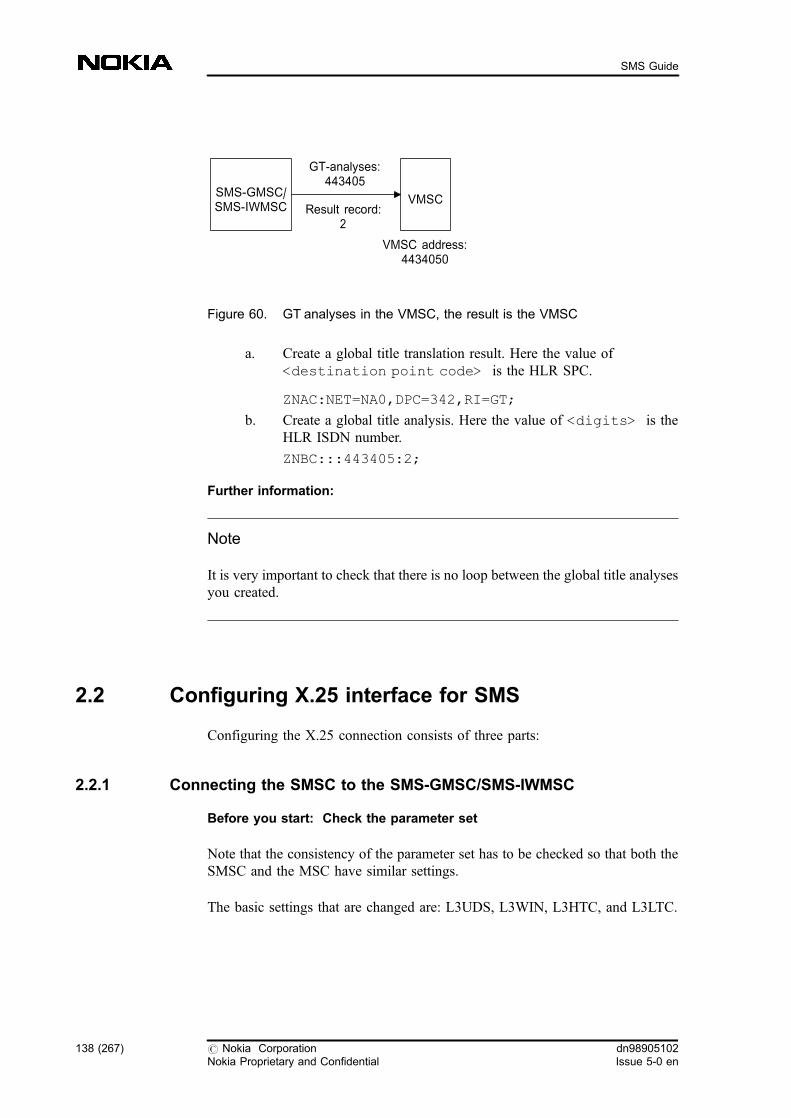
Figure 60. GT analyses in the VMSC, the result is the VMSC
a. Create a global title translation result. Here the value of<destination point code> is the HLR SPC.
ZNAC:NET=NA0,DPC=342,RI=GT;
b. Create a global title analysis. Here the value of <digits> is theHLR ISDN number.
ZNBC:::443405:2;
Further information:
Note
It is very important to check that there is no loop between the global title analysesyou created.
2.2 Configuring X.25 interface for SMS
Configuring the X.25 connection consists of three parts:
2.2.1 Connecting the SMSC to the SMS-GMSC/SMS-IWMSC
Before you start: Check the parameter set
Note that the consistency of the parameter set has to be checked so that both theSMSC and the MSC have similar settings.
The basic settings that are changed are: L3UDS, L3WIN, L3HTC, and L3LTC.
VMSC
GT-analyses:443405
Result record:2
VMSC address:4434050
SMS-GMSC/SMS-IWMSC
138 (267) # Nokia CorporationNokia Proprietary and Confidential
dn98905102Issue 5-0 en
SMS Guide

L3UDS tells the length of the user data, and L3WIN the window size. L3LTC isthe lowest and L3HTC is the highest traffic channel used.
If the X.25 connection from the SMSC to the MSC does not work, check thevalue of the highest traffic channel in the MSC. The DTE entity creates theconnection with the highest, and the DCE entity with the lowest traffic channeldefined. Therefore, make sure that these values are the same in the SMSC and theMSC.
Use command ZQXI; for checking the parameter set.
Steps
1. Create a parameter set (QXC)
ZQXC:<parameter set name>:;
where <parameter set name> is the identifier of the parameter setwith 1 - 8 characters.
2. Modify a parameter set (QXM)
ZQXM:<parameter set name>:<changed parameters>;
3. Set the physical level characteristics for an analogue interface (QTC)
These characteristics are set for a unit which has an interface with the SMS.Repeat the command for each interface. For more detailed information, seeinstructions on OSI management and SMSC Guide to Commissioning forHP 9000/700 and 9000/800.
ZQTC:BDCU,<unit index>:<plug�in unit type>,<plug�inunit index>: <interface type>, <bit rate>;
To find out the unit index, use the command
ZUSI:BDCU;
To find out the analog terminal index, use the command
ZWTI:P:BDCU;
or
ZQTI;
dn98905102Issue 5-0 en
# Nokia CorporationNokia Proprietary and Confidential
139 (267)
Configuring network elements for SMS

4. Create a physical channel (QCS)
Repeat the command for each channel.
ZQCS::BDCU,<unit index>,<terminal number>::<terminal mode>,<X.25 parameter set>;
To find out the unit index, use the command
ZUSI:BDCU;
To find out the analog terminal index, use the command
ZWTI:P:BDCU;
or
ZQTI;
5. Unlock the physical channel (QSC)
Repeat the command for each channel.
ZQSC:<physical channel numbers>,UNL;
where <physical channel numbers> identifies the physicalchannel(s). Characters & and && are allowed.
To find out the number, use the QSI command (address number).
6. Create a channel group (QGC)
Repeat the command for each channel group. The channel group includesall channels to the group.
ZQGC:<physical channel group name>:<physical channelnumber>,,<physical channel priority>;
7. Create the NSAPs (QBN)
ZQBN:<NSAP number>:<NSAP role>:<NSAP type>:DTE=<DTE number>,SPI=<subsequent protocolidentifier>,CHG=<X.25 channel group name>;
Note that CHG is used only for creating remote NSAPs.
140 (267) # Nokia CorporationNokia Proprietary and Confidential
dn98905102Issue 5-0 en
SMS Guide

To find out the C number, use the QNI command:
ZQNI;
8. Create network addresses to connect application to the relevantinterface (QBC)
Create network addresses to connect application to the interface which it isgoing to use. Attach the NSAP addresses of the interfaces to this networkaddress.
ZQBC:<network address name>:<network address role>;
9. Attach NSAPs (QBT)
ZQBT:<network address name>:<NSAP number>;
10. Unlock the NSAP addresses (QBG)
ZQBG:<NSAP number>,<state change>;
11. Create OSI applications (QDL, QDR)
You can create local or remote application.
a. Create a local application, that is, a process that uses OSI services.Create an application to the first CCSU unit only.
ZQDL:<AE name>:::<state change>:<unit type>,<unit index>:<application type>:<networkaddress name>:<P-selector>:<S-selector>:<T-selector>;
b. Create a remote OSI application
ZQDR:<AE name>:::<state change>:<applicationtype>:<network address name>;
12. Set the OSI access control method (QQM, QQC)
There are two alternatives in the MSC for allowing connection requestsfrom outside: either all incoming calls are allowed, or only the calls whoseaddresses are defined as allowed ones.
ZQQM:<access control method>;
If you use the value L (use access control list), add SNPA to OSI accesscontrol list.
dn98905102Issue 5-0 en
# Nokia CorporationNokia Proprietary and Confidential
141 (267)
Configuring network elements for SMS

ZQQC:<SNPA address>;
where <SNPA address> is the remote SMSC DTE address.
Further information:
If the creation of a physical channel fails, check the equipping of the plug-in unitswith following command.
ZWTI:P:BDCU;
Especially wrong memory addresses in plug-unit equipping can cause errorsituations.
Example 1. Connecting the SMSC to the SMS-GMSC/SMS-IWMSC
1. Check the parameter set
ZQXI;
a. Create a parameter set
ZQXC:SMSCSET:;
An example printout:
CREATED X25 CONFIGURATION PARAMETER SET DATA
PARAMETER SET NAME: SMSCSET
==================
MAXIMUM NETWORK SERVICE DATA UNIT LENGTH: 2048 BYTES
L2 CONNECTION MODE: INITIATED AFTER START UP
LEVEL 2 PARAMETERS:
------------------
L2 TIMER T1: 6 SECONDS L2 BITS IN FRAME: 1024 BITS
L2 TIMER T2: NOT IN USE L2 RETRY COUNT: 10 TIMES
L2 TIMER T3: NOT IN USE L2 WINDOW: 7 FRAMES
L2 INTERFRAME FILL: 01111110 L2 LINE DOWN TIMER: 20 (NOT SUPPORTED)
LEVEL 3 PARAMETERS:
------------------
L3 USER DATA SIZE: 128 BYTES
L3 SEND WINDOW SIZE: 2 FRAMES
L3 MODULO: 8
L3 TIMER T20: 180 SECONDS
L3 TIMER T21: 200 SECONDS
L3 TIMER T22: 180 SECONDS L3 RESET RETRY COUNT: 5 TIMES
L3 TIMER T23: 180 SECONDS L3 CLEAR RETRY COUNT: 5 TIMES
L3 FIRST PVC: 0 (= NOT IN USE) L3 LAST PVC: 0 (= NOT IN USE)
L3 LIC: 0 (NOT SUPPORTED) L3 HIC: 0 (NOT SUPPORTED)
L3 LTC: 0 (= NOT IN USE) L3 HTC: 0 (= NOT IN USE)
L3 LOC: 0 (NOT SUPPORTED) L3 HOC: 0 (NOT SUPPORTED)
USER FACILITIES:
---------------
142 (267) # Nokia CorporationNokia Proprietary and Confidential
dn98905102Issue 5-0 en
SMS Guide
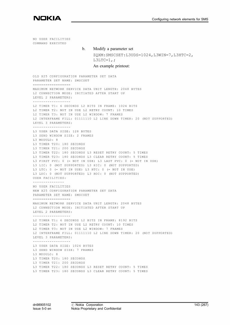
NO USER FACILITIES
COMMAND EXECUTED
b. Modify a parameter set
ZQXM:SMSCSET:L3UDS=1024,L3WIN=7,L3HTC=2,L3LTC=1,;
An example printout:
OLD X25 CONFIGURATION PARAMETER SET DATA
PARAMETER SET NAME: SMSCSET
==================
MAXIMUM NETWORK SERVICE DATA UNIT LENGTH: 2048 BYTES
L2 CONNECTION MODE: INITIATED AFTER START UP
LEVEL 2 PARAMETERS:
------------------
L2 TIMER T1: 6 SECONDS L2 BITS IN FRAME: 1024 BITS
L2 TIMER T2: NOT IN USE L2 RETRY COUNT: 10 TIMES
L2 TIMER T3: NOT IN USE L2 WINDOW: 7 FRAMES
L2 INTERFRAME FILL: 01111110 L2 LINE DOWN TIMER: 20 (NOT SUPPORTED)
LEVEL 3 PARAMETERS:
------------------
L3 USER DATA SIZE: 128 BYTES
L3 SEND WINDOW SIZE: 2 FRAMES
L3 MODULO: 8
L3 TIMER T20: 180 SECONDS
L3 TIMER T21: 200 SECONDS
L3 TIMER T22: 180 SECONDS L3 RESET RETRY COUNT: 5 TIMES
L3 TIMER T23: 180 SECONDS L3 CLEAR RETRY COUNT: 5 TIMES
L3 FIRST PVC: 0 (= NOT IN USE) L3 LAST PVC: 0 (= NOT IN USE)
L3 LIC: 0 (NOT SUPPORTED) L3 HIC: 0 (NOT SUPPORTED)
L3 LTC: 0 (= NOT IN USE) L3 HTC: 0 (= NOT IN USE)
L3 LOC: 0 (NOT SUPPORTED) L3 HOC: 0 (NOT SUPPORTED)
USER FACILITIES:
---------------
NO USER FACILITIES
NEW X25 CONFIGURATION PARAMETER SET DATA
PARAMETER SET NAME: SMSCSET
==================
MAXIMUM NETWORK SERVICE DATA UNIT LENGTH: 2048 BYTES
L2 CONNECTION MODE: INITIATED AFTER START UP
LEVEL 2 PARAMETERS:
------------------
L2 TIMER T1: 6 SECONDS L2 BITS IN FRAME: 8192 BITS
L2 TIMER T2: NOT IN USE L2 RETRY COUNT: 10 TIMES
L2 TIMER T3: NOT IN USE L2 WINDOW: 7 FRAMES
L2 INTERFRAME FILL: 01111110 L2 LINE DOWN TIMER: 20 (NOT SUPPORTED)
LEVEL 3 PARAMETERS:
------------------
L3 USER DATA SIZE: 1024 BYTES
L3 SEND WINDOW SIZE: 7 FRAMES
L3 MODULO: 8
L3 TIMER T20: 180 SECONDS
L3 TIMER T21: 200 SECONDS
L3 TIMER T22: 180 SECONDS L3 RESET RETRY COUNT: 5 TIMES
L3 TIMER T23: 180 SECONDS L3 CLEAR RETRY COUNT: 5 TIMES
dn98905102Issue 5-0 en
# Nokia CorporationNokia Proprietary and Confidential
143 (267)
Configuring network elements for SMS

L3 FIRST PVC: 0 (= NOT IN USE) L3 LAST PVC: 0 (= NOT IN USE)
L3 LIC: 0 (NOT SUPPORTED) L3 HIC: 0 (NOT SUPPORTED)
L3 LTC: 1 L3 HTC: 2
L3 LOC: 0 (NOT SUPPORTED) L3 HOC: 0 (NOT SUPPORTED)
USER FACILITIES:
---------------
NO USER FACILITIES
COMMAND EXECUTED
2. Set the physical level characteristics for an analog interface. Thesecharacteristics are set for a unit which has an interface with the SMS.Repeat the command for each interface.
ZQTC:BDCU,0:AC25S,1:V35,61440:;
Example printouts:
CREATING ANALOG TERMINAL DATA
PIU PIU INTERFACE BIT PHYS
UNIT TYPE INDEX TYPE RATE CHAN NB
---------- ------------- --------- ------ -------
BDCU-0 AC25-S 1 V.35 61440 -
COMMAND EXECUTED
CREATING ANALOG TERMINAL DATA
PIU PIU INTERFACE BIT PHYS
UNIT TYPE INDEX TYPE RATE CHAN NB
---------- ------------- --------- ------ -------
BDCU-0 AC25-S 1 X.21 153600 -
COMMAND EXECUTED
3. Create a physical channel. Repeat the command for each channel.
ZQCS::BDCU,0,1::DCE,SMSCSET:;
An example printout:
CREATED PHYSICAL CHANNEL DATA
SNPA DTE/ X.25 PHYS DATA RATE
CHANNEL SNPA-ADDRESS INTP UNIT TERM DCE PARAM SET LEVEL BITS/S
------- ---------------- ---- -------- ---- ---- --------- ------ ---------
1 SNPA NOT IN USE IGNO BDCU-0 1 DCE SMSCSET V.35 61440
COMMAND EXECUTED
4. Unlock the physical channel. Repeat the command for each channel.
ZQSC:1,UNL;
An example printout:
CHANGING PHYSICAL CHANNEL STATE
CHANNEL OLD STATE NEW STATE INFO
------- --------- --------- ----
1 LOC-ENA UNL-ENA
COMMAND EXECUTED
144 (267) # Nokia CorporationNokia Proprietary and Confidential
dn98905102Issue 5-0 en
SMS Guide
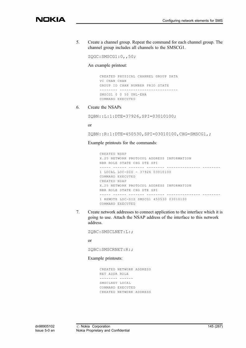
5. Create a channel group. Repeat the command for each channel group. Thechannel group includes all channels to the SMSCG1.
ZQGC:SMSCG1:0,,50;
An example printout:
CREATED PHYSICAL CHANNEL GROUP DATA
VC CHAN CHAN
GROUP ID CHAN NUMBER PRIO STATE
-------- --------------------------
SMSCG1 0 0 50 UNL-ENA
COMMAND EXECUTED
6. Create the NSAPs
ZQBN::L:1:DTE=37926,SPI=03010100;
or
ZQBN::R:1:DTE=450530,SPI=03010100,CHG=SMSCG1,;
Example printouts for the commands:
CREATED NSAP
X.25 NETWORK PROTOCOL ADDRESS INFORMATION
NBR ROLE STATE CHG DTE SPI
----- ------ ------- -------- --------------- --------
1 LOCAL LOC-DIS - 37926 03010100
COMMAND EXECUTED
CREATED NSAP
X.25 NETWORK PROTOCOL ADDRESS INFORMATION
NBR ROLE STATE CHG DTE SPI
----- ------ ------- -------- --------------- --------
1 REMOTE LOC-DIS SMSCG1 450530 03010100
COMMAND EXECUTED
7. Create network addresses to connect application to the interface which it isgoing to use. Attach the NSAP address of the interface to this networkaddress.
ZQBC:SMSCLNET:L:;
or
ZQBC:SMSCRNET:R:;
Example printouts:
CREATED NETWORK ADDRESS
NET ADDR ROLE
-------- ------
SMSCLNET LOCAL
COMMAND EXECUTED
CREATED NETWORK ADDRESS
dn98905102Issue 5-0 en
# Nokia CorporationNokia Proprietary and Confidential
145 (267)
Configuring network elements for SMS
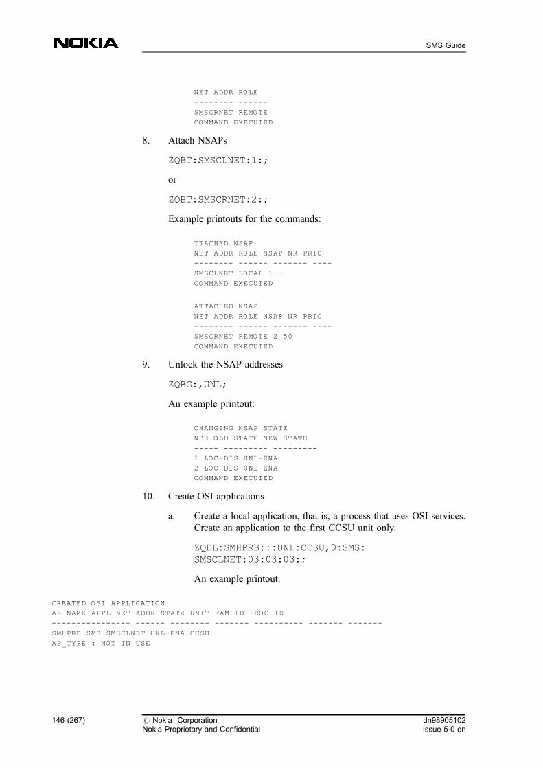
NET ADDR ROLE
-------- ------
SMSCRNET REMOTE
COMMAND EXECUTED
8. Attach NSAPs
ZQBT:SMSCLNET:1:;
or
ZQBT:SMSCRNET:2:;
Example printouts for the commands:
TTACHED NSAP
NET ADDR ROLE NSAP NR PRIO
-------- ------ ------- ----
SMSCLNET LOCAL 1 -
COMMAND EXECUTED
ATTACHED NSAP
NET ADDR ROLE NSAP NR PRIO
-------- ------ ------- ----
SMSCRNET REMOTE 2 50
COMMAND EXECUTED
9. Unlock the NSAP addresses
ZQBG:,UNL;
An example printout:
CHANGING NSAP STATE
NBR OLD STATE NEW STATE
----- --------- ---------
1 LOC-DIS UNL-ENA
2 LOC-DIS UNL-ENA
COMMAND EXECUTED
10. Create OSI applications
a. Create a local application, that is, a process that uses OSI services.Create an application to the first CCSU unit only.
ZQDL:SMHPRB:::UNL:CCSU,0:SMS:SMSCLNET:03:03:03:;
An example printout:
CREATED OSI APPLICATION
AE-NAME APPL NET ADDR STATE UNIT FAM ID PROC ID
---------------- ------ -------- ------- ---------- ------- -------
SMHPRB SMS SMSCLNET UNL-ENA CCSU
AP_TYPE : NOT IN USE
146 (267) # Nokia CorporationNokia Proprietary and Confidential
dn98905102Issue 5-0 en
SMS Guide
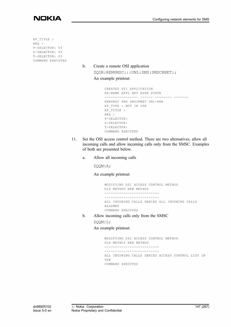
AP_TITLE :
AEQ :
P-SELECTOR: 03
S-SELECTOR: 03
T-SELECTOR: 03
COMMAND EXECUTED
b. Create a remote OSI application
ZQDR:REMSMSC:::UNL:SMS:SMSCRNET:;
An example printout:
CREATED OSI APPLICATION
AE-NAME APPL NET ADDR STATE
---------------- ------ -------- -------
REMSMSC SMS SMSCRNET UNL-ENA
AP_TYPE : NOT IN USE
AP_TITLE :
AEQ :
P-SELECTOR:
S-SELECTOR:
T-SELECTOR:
COMMAND EXECUTED
11. Set the OSI access control method. There are two alternatives, allow allincoming calls and allow incoming calls only from the SMSC. Examplesof both are presented below.
a. Allow all incoming calls
ZQQM:A;
An example printout:
MODIFYING OSI ACCESS CONTROL METHOD
OLD METHOD NEW METHOD
--------------------------
--------------------------
ALL INCOMING CALLS DENIED ALL INCOMING CALLS
ALLOWED
COMMAND EXECUTED
b. Allow incoming calls only from the SMSC
ZQQM:L;
An example printout:
MODIFYING OSI ACCESS CONTROL METHOD
OLD METHOD NEW METHOD
--------------------------
--------------------------
ALL INCOMING CALLS DENIED ACCESS CONTROL LIST IN
USE
COMMAND EXECUTED
dn98905102Issue 5-0 en
# Nokia CorporationNokia Proprietary and Confidential
147 (267)
Configuring network elements for SMS
2.2.2 Creating analysis on SMS application level in the MSC
Steps
1. Create SMS routing support analysis (CFU)
You can create a SMS routing support analysis for defining the case whenSMS routing analysis is started.
ZCFU:SMSC=<smsc address>;
Note
You can execute this command only if you have Feature 1165: Short MessageServices GSM Phase 2+ Enhancements in use in your network.
If you do not have feature 1165, for the available conditions see SMS routinganalysis .
2. Create an SMS routing analysis (CFE)
ZCFE:PID=<protocol identifier>,SAP=<serviceapplication prefix>,SAPTYPE=<service applicationprefix type><option>:SMSC=<short message servicecentre address>,TC=<tariff class>,SAN=<serviceapplication name>;
Note
This step is optional and is necessary only if you want to route the subscriber'sSMS request to the service application in the desired SMSC or if you want tocreate different tariff classes for MO-SMs.
3. Create an SMSC address analysis (CFS)
ZCFS:<SMSC address>,<result type>:<SMSC level>:<operation>:<application entity name>;
By giving multiple X.25 connections (applications entity names) you canenable load sharing in your system.
148 (267) # Nokia CorporationNokia Proprietary and Confidential
dn98905102Issue 5-0 en
SMS Guide
For more information, see SMS load sharing .
ZCFS:<SMSC address>,<result type>:<SMSC level>:ADD:<application entity name1>,<application entityname2>,<application entity name3>,<applicationentity name4>,<application entity name5>;
4. Preconfigure the SMSC address, if necessary
If you want to use always the same SMSC address towards the MS, youhave to add the address to the UTPFIL.
Note
This step is necessary only if you do not have Feature 1165: Short MessageServices GSM Phase 2+ Enhancements in use in your network.
For more information, see Working examples for SMS management .
a. Find out the UTPFIL and its number running in the CCSU / GSU(WQV, DFL)
ZWQV:CCSU:UTP%;
ZDFL:CCSU,0:NAME= <UTPFIL name>;
b. Find the CM in WO-EX state
ZUSI:CM;
c. Find out three free records in UTPFIL (DFD)
ZDFD:CM,x:<file number>;
where x means the active CM, <file number> is the number forthe UTPFIL, given as a hexadecimal. If the variant part (the last 4digits) is 0000, it can be omitted. For example, 20000 can be givenas 2.
d. Add the SMSC address into UTPFIL records
Make sure that you do the changes in every CCSU.
e. Add the SMSC address into UTPFIL records
ZDFS:CM,x:<file number>,<record number>;
f. Restart every CCSU unit one by one
Further information:
Example 2. Creating an analysis for the SMSC address in the SMS-
dn98905102Issue 5-0 en
# Nokia CorporationNokia Proprietary and Confidential
149 (267)
Configuring network elements for SMS
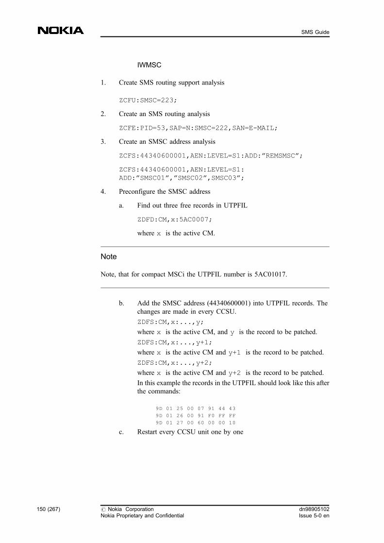
IWMSC
1. Create SMS routing support analysis
ZCFU:SMSC=223;
2. Create an SMS routing analysis
ZCFE:PID=53,SAP=N:SMSC=222,SAN=E-MAIL;
3. Create an SMSC address analysis
ZCFS:44340600001,AEN:LEVEL=S1:ADD:�REMSMSC�;
ZCFS:44340600001,AEN:LEVEL=S1:ADD:�SMSC01�,�SMSC02�,SMSC03�;
4. Preconfigure the SMSC address
a. Find out three free records in UTPFIL
ZDFD:CM,x:5AC0007;
where x is the active CM.
Note
Note, that for compact MSCi the UTPFIL number is 5AC01017.
b. Add the SMSC address (44340600001) into UTPFIL records. Thechanges are made in every CCSU.
ZDFS:CM,x:...,y;
where x is the active CM, and y is the record to be patched.
ZDFS:CM,x:...,y+1;
where x is the active CM and y+1 is the record to be patched.
ZDFS:CM,x:...,y+2;
where x is the active CM and y+2 is the record to be patched.
In this example the records in the UTPFIL should look like this afterthe commands:
9D 01 25 00 07 91 44 43
9D 01 26 00 91 F0 FF FF
9D 01 27 00 60 00 00 10
c. Restart every CCSU unit one by one
150 (267) # Nokia CorporationNokia Proprietary and Confidential
dn98905102Issue 5-0 en
SMS Guide

2.2.3 Setting parameters so that GSM phase 2+ and MT-SM are supported
For more information, see MAP in SMS especially MAP version 3.
MAP version 3 related instructions can be found in section Handling SMS-related MAP operations in MSC and HLR .
Steps
1. Set parameters so that GSM phase 2+ is supported by default (OPH)
a. Check the SMS-related application context-specific MAP versions
ZOPH:INTERR;
Examine the SMS-related application contexts on the executionprintout.
. 20 shortMsgGateway
. 21 shortMsgMO-Relay
. 23 shorMsgAlert
Note that MAP version 2 is allowed only in this applicationcontext. There is no change for MAP version 3.
. 24 mwdMngt
. 25 shortMsgMT-Relay
b. Modify the parameters, if necessary
ZOPH:MODIFY:AC=<application context>:VER=<MAPversion>;
2. Make sure MT-SM is supported in the MSC/VLR (MXM)
You can activate MT-SMs by giving the following commands in the VLR:
ZMXM::::T21=Y;
ZMXM::::T22=Y;
Further information:
Example 3. Setting parameters so that GSM phase 2+ and MT-SM aresupported
1. Set parameters so that GSM phase 2+ is supported by default
a. Check the SMS-related application context-specific MAP versions
ZOPH:INTERR;
dn98905102Issue 5-0 en
# Nokia CorporationNokia Proprietary and Confidential
151 (267)
Configuring network elements for SMS
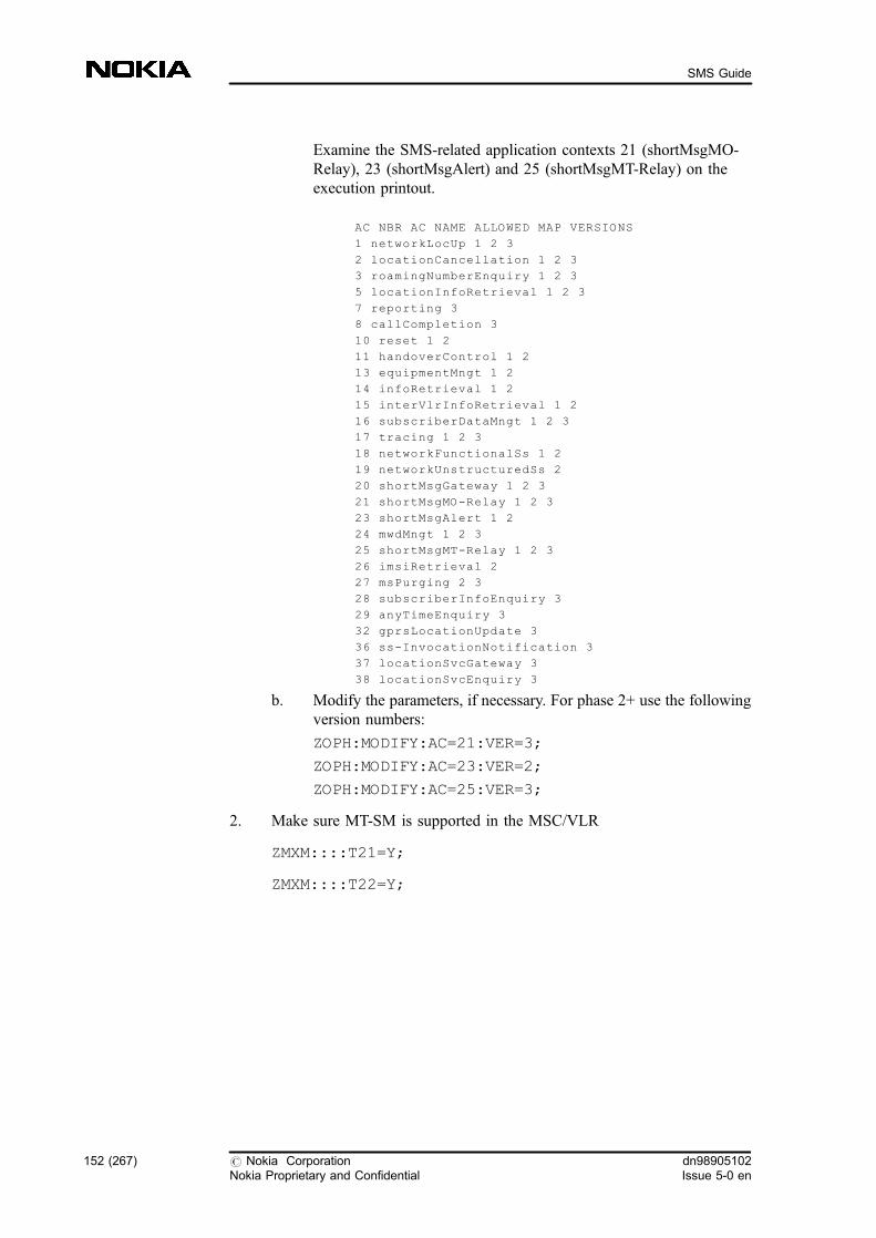
Examine the SMS-related application contexts 21 (shortMsgMO-Relay), 23 (shortMsgAlert) and 25 (shortMsgMT-Relay) on theexecution printout.
AC NBR AC NAME ALLOWED MAP VERSIONS
1 networkLocUp 1 2 3
2 locationCancellation 1 2 3
3 roamingNumberEnquiry 1 2 3
5 locationInfoRetrieval 1 2 3
7 reporting 3
8 callCompletion 3
10 reset 1 2
11 handoverControl 1 2
13 equipmentMngt 1 2
14 infoRetrieval 1 2
15 interVlrInfoRetrieval 1 2
16 subscriberDataMngt 1 2 3
17 tracing 1 2 3
18 networkFunctionalSs 1 2
19 networkUnstructuredSs 2
20 shortMsgGateway 1 2 3
21 shortMsgMO-Relay 1 2 3
23 shortMsgAlert 1 2
24 mwdMngt 1 2 3
25 shortMsgMT-Relay 1 2 3
26 imsiRetrieval 2
27 msPurging 2 3
28 subscriberInfoEnquiry 3
29 anyTimeEnquiry 3
32 gprsLocationUpdate 3
36 ss-InvocationNotification 3
37 locationSvcGateway 3
38 locationSvcEnquiry 3
b. Modify the parameters, if necessary. For phase 2+ use the followingversion numbers:
ZOPH:MODIFY:AC=21:VER=3;
ZOPH:MODIFY:AC=23:VER=2;
ZOPH:MODIFY:AC=25:VER=3;
2. Make sure MT-SM is supported in the MSC/VLR
ZMXM::::T21=Y;
ZMXM::::T22=Y;
152 (267) # Nokia CorporationNokia Proprietary and Confidential
dn98905102Issue 5-0 en
SMS Guide
2.3 Configuring TCP/IP connection for SMS
The TCP/IP connection is an alternative to the X.25 interface between the SMSCand the MSC. For more information on TCP/IP, see Interfaces between SMSnetwork elements , SMRSE in SMS , and Comparison of SMS functionalities incase of SMRSE over X.25 or TCP/IP and SS7 MAP SMSC .
Configuring the TCP/IP connection consists of three parts:
2.3.1 Connecting the SMSC to the SMS-GMSC/SMS-IWMSC
Steps
1. Connect the SMSC to the MSC
Connect the SMSC to the MSC physically with the Ethernet cable. In caseof i-series products the TCP/IP connection is accessible through the CPUcard of the BDCU, otherwise the COCEN card of the BDCU is used.
2. Create the COCEN plug-in units to the system in case of subrack MSC(WTP)
ZWTP:BDCU,0:COCEN,<piu index>,<track>:INT=<interrupt level>;
3. Create a TCP/IP network interface for each BDCU unit (QRN)
Create a TCP/IP network interface for each BDCU unit running the shortmessage transfer system by using the QRN command. Unblock the createdinterfaces.
ZQRN:BDCU,0::<interface name>:<destination IPaddress>,<L/P>,<DEL>:<netmask length>:<state>;
where:
<interface name>
. It is EL0 in case of a cartridge MSC.
. It is COx (x means the PIU index) in case of a subrack MSC.
Expected outcome
You can check the terminal number available in BDCU-0 for the networkinterface with the following command:
dn98905102Issue 5-0 en
# Nokia CorporationNokia Proprietary and Confidential
153 (267)
Configuring network elements for SMS

ZWTI:P:BDCU,0;
Note
In i-series products the terminal number of the CPU card can be used, which isusually 0.
4. Check ZIPBOXMX.IMG file (MXP)
Make sure that the ZIPBOXMX.IMG file can be found in the BLCODEdirectory. You can check it with the following Service Terminal commandin the OMU.
ZMXP:WO-BLCODE/ZIPBOXMX.IMG:*
5. Restart BDCU units (USU)
Restart the BDCU units which you modified. Force the units to load thecode from the disk with the USU command.
ZUSU:BDCU,0:C=DSK;
Further information:
Example 4. Connecting the SMSC to the SMS-GMSC/SMS-IWMSC
1. Connect the SMSC to the MSC physically with the Ethernet cable. In caseof i-series products the TCP/IP connection is accessible through the CPUcard of the BDCU, otherwise the COCEN card of the BDCU is used.
2. Create the COCEN plug-in units for the BDCU-0. The plug-in unit islocated in slot 5 in the cartridge, and its interrupt level is 22H. The tracknumber is 47.
ZWTP:BDCU,0:COCEN,5,47:INT=22;
3. Create a TCP/IP network interface for each BDCU unit running the shortmessage transfer system. The netmask length is 25. Unblock the createdinterface.
ZQRN:BDCU,0:CO5:188.67.89.128,P:25:UP;
154 (267) # Nokia CorporationNokia Proprietary and Confidential
dn98905102Issue 5-0 en
SMS Guide

4. Make sure that the ZIPBOXMX.IMG file can be found in the BLCODEdirectory. You can check it with the following Service Terminal commandin the OMU:
ZMXP:WO-BLCODE/ZIPBOXMX.IMG:*
5. Restart the BDCU units which you modified. Force the units to load thecode from the disk.
ZUSU:BDCU,0:C=DSK;
2.3.2 Creating analysis on SMS application level in the MSC
Steps
1. Create SMS routing support analysis (CFU)
You can create a SMS routing support analysis for defining the case whenSMS routing analysis is started.
ZCFU:SMSC=<smsc address>;
Note
You can execute this command only if you have Feature 1165: Short MessageServices GSM Phase 2+ Enhancements in use in your network.
If you do not have feature 1165, for the available conditions, see SMS routinganalysis .
2. Create an SMS routing analysis (CFE)
Note
This step is optional and is necessary only if you want to route the subscriber'sSMS request to the service application in the desired SMSC or if you want tocreate different tariff classes for MO-SMs.
dn98905102Issue 5-0 en
# Nokia CorporationNokia Proprietary and Confidential
155 (267)
Configuring network elements for SMS
ZCFE:PID=<protocol identifier>,SAP=<serviceapplication prefix>,SAPTYPE=<service applicationprefix type><option>:SMSC=<short message servicecentre address>,TC=<tariff class>,SAN=<serviceapplication name>;
3. Create an SMSC address analysis (CFS)
ZCFS:<SMSC address>,IP:LEVEL=<SMSC level>,PASSW=<password>:<operation>:<IP address>;
4. Preconfigure the SMSC address, if necessary
If you want to use always the same SMSC address towards the MS, youhave to add the address to the UTPFIL.
For more information, see Working examples for SMS management .
a. Find out the UTPFIL and its number running in the CCSU / GSU(WQV, DFL)
ZWQV:CCSU:UTP%;
ZDFL:CCSU,0:NAME= <UTPFIL name>;
b. Find the CM in WO-EX state
ZUSI:CM;
c. Find out three free records in UTPFIL (DFD)
ZDFD:CM,x:<file number>;
where <file number> is the number for the UTPFIL, given as ahexadecimal. If the variant part (the last 4 digits) is 0000, it can beomitted. For example, 20000 can be given as 2.
d. Add the SMSC address into UTPFIL records
Make sure that you do the changes in every CCSU.
ZDFS:CM,x:<file number>,<record number>;
e. Restart every CCSU unit one by one
2.3.3 Setting parameters so that GSM phase 2+ and MT-SM are supported
See also MAP in SMS , especially MAP version 3 for more information.
MAP version 3 related instructions can be found in Handling SMS-related MAPoperations in MSC and HLR .
156 (267) # Nokia CorporationNokia Proprietary and Confidential
dn98905102Issue 5-0 en
SMS Guide
Steps
1. Set parameters so that GSM phase 2+ is supported by default (OPH)
a. Check the SMS-related application context-specific MAP versions
ZOPH:INTERR;
Examine the SMS-related application contexts on the executionprintout.
. 20 shortMsgGateway
. 21 shortMsgMO-Relay
. 23 shorMsgAlert
Note that MAP version 2 is allowed only in this applicationcontext. There is no change for MAP version 3.
. 24 mwdMngt
. 25 shortMsgMT-Relay
b. Modify the parameters, if necessary
ZOPH:MODIFY:AC=<application context>:VER=<MAPversion>;
2. Check MT-SM support in MSC/VLR (MXM)
Make sure MT-SM is supported in the MSC/VLR. You can activate themby giving the following commands in the VLR:
ZMXM::::T21=Y;
ZMXM::::T22=Y;
Further information:
Example 5. Setting parameters so that GSM phase 2+ and MT-SM aresupported
1. Set parameters so that GSM phase 2+ is supported by default
a. Check the SMS-related application context-specific MAP versions.
ZOPH:INTERR;
Examine the SMS-related application contexts 21 (shortMsgMO-Relay), 23 (shortMsgAlert) and 25 (shortMsgMT-Relay) on theexecution printout.
AC NBR AC NAME ALLOWED MAP VERSIONS
1 networkLocUp 1 2 3
dn98905102Issue 5-0 en
# Nokia CorporationNokia Proprietary and Confidential
157 (267)
Configuring network elements for SMS
2 locationCancellation 1 2 3
3 roamingNumberEnquiry 1 2 3
5 locationInfoRetrieval 1 2 3
7 reporting 3
8 callCompletion 3
10 reset 1 2
11 handoverControl 1 2
13 equipmentMngt 1 2
14 infoRetrieval 1 2
15 interVlrInfoRetrieval 1 2
16 subscriberDataMngt 1 2 3
17 tracing 1 2 3
18 networkFunctionalSs 1 2
19 networkUnstructuredSs 2
20 shortMsgGateway 1 2 3
21 shortMsgMO-Relay 1 2 3
23 shortMsgAlert 1 2
24 mwdMngt 1 2 3
25 shortMsgMT-Relay 1 2 3
26 imsiRetrieval 2
27 msPurging 2 3
28 subscriberInfoEnquiry 3
29 anyTimeEnquiry 3
32 gprsLocationUpdate 3
36 ss-InvocationNotification 3
37 locationSvcGateway 3
38 locationSvcEnquiry 3
b. Modify the parameters, if necessary. For phase 2+ use the followingversion numbers:
ZOPH:MODIFY:AC=21:VER=3;
ZOPH:MODIFY:AC=23:VER=2;
ZOPH:MODIFY:AC=25:VER=3;
2. Make sure MT-SM is supported in the MSC/VLR
ZMXM::::T21=Y;
ZMXM::::T22=Y;
2.4 Handling SMS-related MAP operations in MSC andHLR
The possibility to set MAP version 3 by MMLs appears only if you have Feature1043: Short Message Services GSM Phase 2+ in use in your network . FromFeature 1043 point of view the SMS related Application Context (AC) defaultsshould be set to version 3.
These ACs are the following:
158 (267) # Nokia CorporationNokia Proprietary and Confidential
dn98905102Issue 5-0 en
SMS Guide

. shortMsgGateway 20
. shortMsgMO-Relay 21
. mwdMngt 24 and
. shortMsgMT-Relay 25
If the MAP version of shortMsgMO-Relay (21) Application Context is set toversion 3, then the IMSI of A-subscriber is sent to SMS-IWMSC form theVMSC.
Note
If there is MAP version 3 in the VMSC, Feature 714: Short Message ServiceEnhancements is disregarded and normal reason code (MNRR) is sent backinstead of system failure, which makes it possible to have Feature 714: ShortMessage Service Enhancements and Feature 1043: Short Message Services,GSM Phase 2+ switched on at the same time.
Steps
1. Interrogate the Application Context-Specific defaults (OPH)
ZOPH:INTERR;
2. Set the version of SMS related Application Contexts to version 3(OPH)
Set the version of SMS related Application Contexts (20, 21, 24, 25) toversion 3.
ZOPH:MODIFY:AC=<AC code>:VER=<version number>;
If you do not want to use MAP version 3 signalling between networkelements for SMS operations, set back the MAP version of SMS relatedoperations to version 2 using the MML commands mentioned above (OPHfor Application Contexts, OPA and OPR for Error Counters, OPS forAlarm Thresholds).
Further information:
Example 6.
ZOPH:MODIFY:AC=20:VER=3;
dn98905102Issue 5-0 en
# Nokia CorporationNokia Proprietary and Confidential
159 (267)
Configuring network elements for SMS
Further information:
Due to the new MAP version, there is a change in the Network Entity AddressAnalysis Result Handling. In the OPV command the new MAP version 3 is also apossible value for the MAP operation version.
2.4.1 Handling Error counters in SMS
Optionally, you can activate/deactivate/reset Error Counters to MAP operationsusing the OPA and OPR commands. The Error Counters can be activated/deactivated/reset to MAP version 3 operations also.
Steps
1. Interrogate the Error Counters (OPA)
ZOPA;
2. Activate/Deactivate Error Counter (OPA)
ZOPA:<operation code>:<version number>:<Activate/Deactivate/Interrogate>;
Further information:
Example 7.
ZOPA:2:3:ACT;
3. Setting Error Counters for MAP version 3 (OPR)
a. Interrogate the Error Counter
ZOPA;
b. Reset Error Counter
ZOPR:<operation code>:<version number>;
Further information:
Example 8.
ZOPR:2:3;
4. Setting Error Alarm Threshold (OPS)
160 (267) # Nokia CorporationNokia Proprietary and Confidential
dn98905102Issue 5-0 en
SMS Guide

a. Interrogate Error Alarm Thresholds for MAP operation
ZOPQ:<operation code>;
for example: ZOPQ:2;
b. Set Error Alarm Thresholds for MAP operation
ZOPS:<operation code>:<version number>:LOW=<0...1000>,MEDIUM=<0...1000>,HIGH=<0...1000>;
for example: ZOPS:2:3:LOW=100,MEDIUM=150,HIGH=200;
The HIGH value should be higher than the MEDIUM value, and theMEDIUM value should be higher than the LOW value.
2.5 Handling the Welcome SM related parameters
Description of the Welcome SM functionality can be found in Welcome SM to theroamer .
Before you start
The 'Welcome-SM' related parameters appears only if the WELCOME_SMFIFILE parameter is set to value ACTIVE.
If you have the 'Welcome-SM' function you can activate it by MML commands:
. The 'Welcome-SM' function can be activated by setting theWELCOME_SM (class 2) FIFILE parameter to A (activate).
ZWOA:<parameter_class>,<parameter_number>,<activation_status>;
Where:
<parameter_class>Parameter class in FIFILE (=2).
<parameter_number>The number of the WELCOME_SM parameter.
<activation_status>Given value can be D (deactive) or A (active).
The parameter can be checked by the WOS command:
dn98905102Issue 5-0 en
# Nokia CorporationNokia Proprietary and Confidential
161 (267)
Configuring network elements for SMS

ZWOS:<parameter_class>,<parameter_number>;
Steps
1. Set the SMSC address (in MSC and HLR) (WVS)
ZWVS:SCADDR=<smsc_address>:NP=<numbering_plan>,TON=<type_of_number>;
Example 9. Set the SMSC address
ZWVS:SCADDR=491770000097:NP=E164,TON=INT;
2. Set the SMSC application address (in MSC and HLR) (WVS)
ZWVS:WSCAPP=<smsc_application_address>:NP=<numbering_plan>,TON=<type_of_number>;
Example 10. Set the SMSC application address
ZWVS:WSCAPP=491776789:NP=E164,TON=INT;
3. Set the Configurable MSISDN address of virtual subscriber (WVS)
ZWVS:CMSISDN=<cmsisdn_address>:NP=<numbering_plan>,TON=<type_of_number>;
Note
After setting these three parameters, you need to wait 2 minutes to get the globaldata updated in MSC.
Example 11. Set the Configurable MSISDN address
ZWVS:CMSISDN=491774020388:NP=E164,TON=INT;
4. Create virtual subscriber in the HLR if you use MAP version 2 (MIC)
ZMIC:IMSI=<imsi>,MSISDN=<msisdn>;
Example 12.
ZMIC:IMSI=262030024020388,MSISDN=491774020388;
162 (267) # Nokia CorporationNokia Proprietary and Confidential
dn98905102Issue 5-0 en
SMS Guide
5. Interrogate the parameters (in MSC and HLR) (WVI)
a. Interrogate SMSC address
ZWVI:SCADDR;
b. Interrogate SMSC application address
ZWVI:WSCAPP;
c. Interrogate Configurable MSISDN address
ZWVI:CMSISDN;
6. Remove the parameters (in MSC and HLR) (WVR)
a. Remove the SMSC address
ZWVR:SCADDR=<smsc_address>:NP=<numbering_plan>,TON=<type_of_number>;
for example: ZWVR:SCADDR=491770000097:NP=E164,TON=INT;
b. Remove the SMSC application address
ZWVR:WSCAPP=<smsc_application_address>:NP=<numbering_plan>,TON=<type_of_number>;
for example: ZWVR:WSCAPP=491776789:NP=E164,TON=INT;
c. Remove the Configurable MSISDN address
ZWVR:CMSISDN=<cmsisdn_address>:NP=<numbering_plan>,TON=<type_of_number>;
for example: ZWVR:CMSISDN=491774020388:NP=E164,TON=INT;
d. Remove virtual subscriber form HLR
ZMID:IMSI=<imsi> or MSISDN=<msisdn>;
dn98905102Issue 5-0 en
# Nokia CorporationNokia Proprietary and Confidential
163 (267)
Configuring network elements for SMS

164 (267) # Nokia CorporationNokia Proprietary and Confidential
dn98905102Issue 5-0 en
SMS Guide

3 Managing SMS subscriber-specific data
The subscriber management functions allow the addition and deletion of thesubscriber's short message services. The subscriber can use the SM services onlyif SMS is provided for him/her through subscriber management. Define the SMSbasic services by using the MB command group.
For the whole topic summary, see Short Message Services Overview.
Steps
1. Create SMS for a subscriber in HLR (MBF, MBC)
a. Create SMS for a subscriber in HLR (MBF, MBC)
. If you want to create a basic service with a new basic servicecode index for a subscriber, you must create first the newbasic service code index with the MBF command.
. Create the new basic service for the subscriber with the MBCcommand afterwards. For more information, see instructionson Basic Service Handling .
. The recommended way of creating SMS for a number ofsubscribers at a time is to use multiple subscribers handling.For more information, see Subscriber Administration .
b. Create SMS for subscriber
ZMBC:IMSI=<international mobile subscriberidentity>,MSISDN=<mobile subscriberinternational ISDN number>,BSERV=<basic servicecode>;
For IN SMS-related information, see Handling of IN SMS .
Further information:
Example 13. Creating SMS for a subscriber
Create a basic service for a subscriber whose IMSI number is 244041112346 andMSISDN number 358401154322. The teleservice to be created is 'short messageMT/PP' (T21). Other parameters have default values.
dn98905102Issue 5-0 en
# Nokia CorporationNokia Proprietary and Confidential
165 (267)
Managing SMS subscriber-specific data
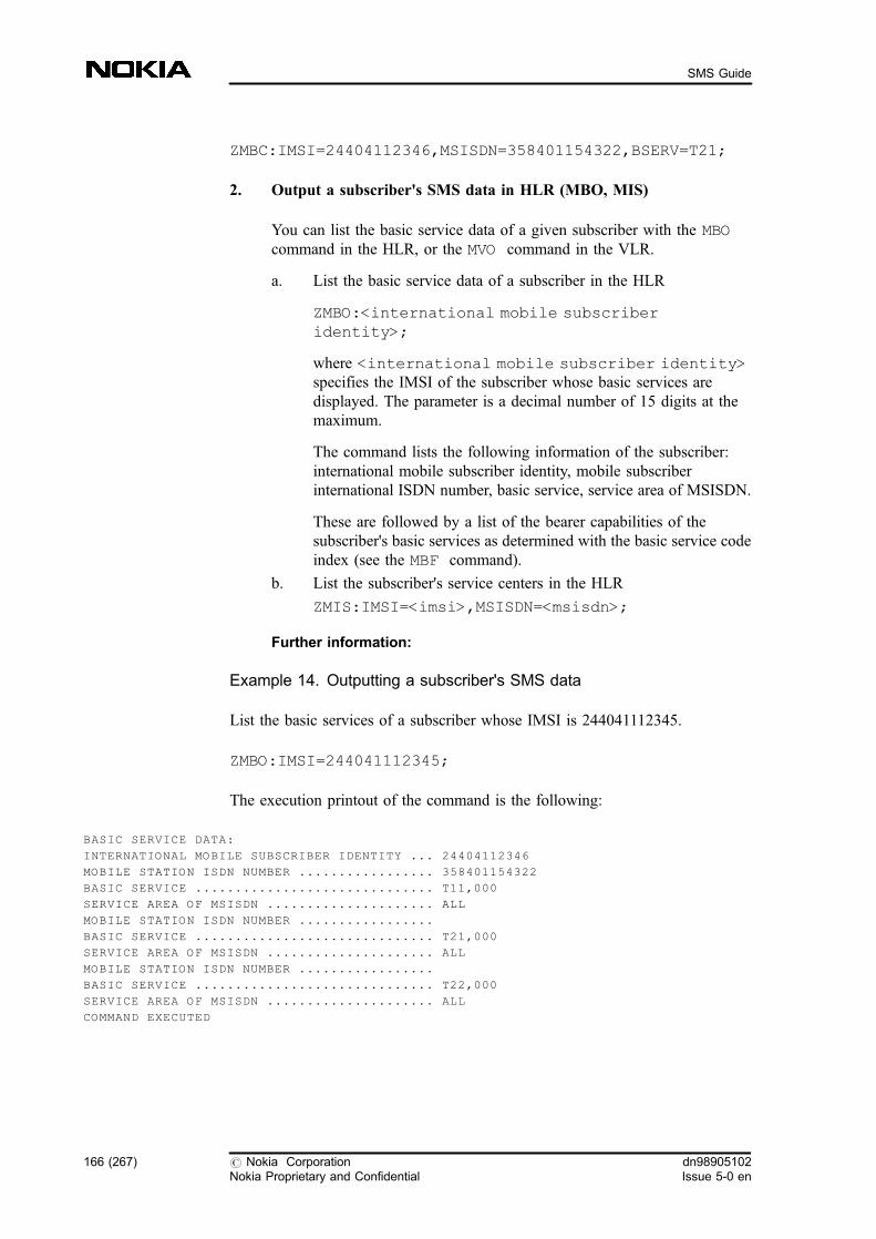
ZMBC:IMSI=24404112346,MSISDN=358401154322,BSERV=T21;
2. Output a subscriber's SMS data in HLR (MBO, MIS)
You can list the basic service data of a given subscriber with the MBOcommand in the HLR, or the MVO command in the VLR.
a. List the basic service data of a subscriber in the HLR
ZMBO:<international mobile subscriberidentity>;
where <international mobile subscriber identity>specifies the IMSI of the subscriber whose basic services aredisplayed. The parameter is a decimal number of 15 digits at themaximum.
The command lists the following information of the subscriber:international mobile subscriber identity, mobile subscriberinternational ISDN number, basic service, service area of MSISDN.
These are followed by a list of the bearer capabilities of thesubscriber's basic services as determined with the basic service codeindex (see the MBF command).
b. List the subscriber's service centers in the HLR
ZMIS:IMSI=<imsi>,MSISDN=<msisdn>;
Further information:
Example 14. Outputting a subscriber's SMS data
List the basic services of a subscriber whose IMSI is 244041112345.
ZMBO:IMSI=244041112345;
The execution printout of the command is the following:
BASIC SERVICE DATA:
INTERNATIONAL MOBILE SUBSCRIBER IDENTITY ... 24404112346
MOBILE STATION ISDN NUMBER ................. 358401154322
BASIC SERVICE .............................. T11,000
SERVICE AREA OF MSISDN ..................... ALL
MOBILE STATION ISDN NUMBER .................
BASIC SERVICE .............................. T21,000
SERVICE AREA OF MSISDN ..................... ALL
MOBILE STATION ISDN NUMBER .................
BASIC SERVICE .............................. T22,000
SERVICE AREA OF MSISDN ..................... ALL
COMMAND EXECUTED
166 (267) # Nokia CorporationNokia Proprietary and Confidential
dn98905102Issue 5-0 en
SMS Guide

Figure 61. An example of outputting a subscriber's SMS data
Example 15. Listing the subscribers service centers in the HLR
Display the service center addresses of subscriber whose IMSI number is244051112345.
ZMIS: IMSI=2440511123445;
The execution printout of the command is the following:
INTERNATIONAL MOBILE SUBSCRIBER IDENTITY ...... 244051112345
MOBILE STATION NOT REACHABLE FLAG ............. Y
MOBILE STATION NOT REACHABLE FOR GPRS FLAG .....N
MOBILE STATION MEMORY CAPACITY EXCEEDED FLAG .. N
MOBILE STATION NOT REACHABLE REASON FOR GPRS: IMSIDET!!!!!!
MOBILE STATION NOT REACHABLE REASON FOR NON GPRS: USUBMSC
SERVICE CENTER ADDRESS(ES)
--------------------------------------------------
12345678
87654321
COMMAND EXECUTED
The fields in the execution printout have the following meanings:
MOBILE STATION NOT REACHABLE FLAGThe value Y (Yes) in this field indicates that an attemptto transfer a short message has been unsuccessfulbecause the subscriber has not been reached.
MOBILE STATION NOT REACHABLE FOR GPRS FLAGThe value Y (Yes) in this field indicates that an attemptto transfer a short message through GPRS has beenunsuccessful because the subscriber has not beenreached.
MOBILE STATION MEMORY CAPACITY EXCEEDED FLAGThe value Y (Yes) in this field indicates that an attemptto transfer a short message has been unsuccessfulbecause the mobile memory capacity has beenexceeded.
MOBILE STATION NOT REACHABLE REASON FOR GPRS orMOBILE STATION NOT REACHABLE REASONFOR NON GPRSThese fields give the reason why a mobile station is notreachable for General Packet Radio Service (GPRS) orfor non-GPRS. The possible reasons are the following:
dn98905102Issue 5-0 en
# Nokia CorporationNokia Proprietary and Confidential
167 (267)
Managing SMS subscriber-specific data
. NPMSC (no paging response through the MSC)
. IMSIDET (IMSI detached)
. NPSGSN (no paging response through theSGSN)
. GPRSDET (GPRS detached)
. USUBMSC (Unidentified subscriber through theMSC)
. USUBSGSN (Unidentified subscriber throughthe SGSN)
3. Delete a subscriber's SMS (MBD)
a. Delete basic services from a subscriber (MBD)
Note
You cannot delete a subscriber's primary basic service.
ZMBD:<international mobile subscriberidentity>,<mobile subscriber international ISDNnumber>;
Further information:
Example 16. Deleting a subscriber's SMS
Delete basic service data from a subscriber whose IMSI is 244041112345. TheMSISDN number of the basic service to be deleted is 358401154321.
ZMBD:IMSI=244041112345,MSISDN=358401154321;
4. Prevent roaming from other networks
A subscriber can activate normal MT and MO barrings for SMS. You canactivate ODB categories that affect also the subscriber's MO-SMs and MT-SMs. For more information, see Feature 220: Operator Determined Barring.
You can also use HLR parameters to prevent the sending of MT-SMS andMO-SMS basic services to a given PLMN, in which case the subscribercannot receive or send SMs when roaming in the given network.
168 (267) # Nokia CorporationNokia Proprietary and Confidential
dn98905102Issue 5-0 en
SMS Guide
You can also affect the sending and receiving of SMs with Feature 910: INShort Message Service . The GSM barrings and operator-determinedbarrings do not have an effect if the subscriber's SMs go through SGSN.For more information, see the feature description of Feature 857: Supportfor General Packet Radio System . The HLR contains a separate parametermanagement for a GPRS subscriber's MT-SMS and MO-SMS basicservices.
dn98905102Issue 5-0 en
# Nokia CorporationNokia Proprietary and Confidential
169 (267)
Managing SMS subscriber-specific data
170 (267) # Nokia CorporationNokia Proprietary and Confidential
dn98905102Issue 5-0 en
SMS Guide
4 Managing SMS network element-specificdata
This section gives procedural information on various network element-relatedfunctions, such as user data and MNRR handling, activation of picture messageinformation, SMS prevention, SMS measurement, and routing enhancement.
For the whole topic summary, see Short Message Services Overview.
4.1 Handling User Data in SMS
The transfer of UserData in MO/MT-SM with positive and negativeacknowledgement requires MAP version 3 SMS-related operations between thenetwork elements. It means that the version of the SMS-related MAP operationsshould be set to version 3 both in the MSC and HLR. For the ability to transferthe UserData to the SMSC, the SMSC should be connected to the MSC throughTCP/IP. In this case the SMSC level should be set to SMS phase 2+ (S3) in theMSC using the CFS command.
Before you start
If you have Feature 1043: Short MessageServices GSM Phase 2+ in use, thenetwork provides full support of SMS GSM phase 2+ standard and MAP version3 (SMS-related operations). This parameter should be set both in the MSC andHLR.
The MAP version of the SMS-related Application contexts should be set to MAPversion 3, as described in Handling SMS-related MAP operations in MSC andHLR .
Steps
1. Set the SMSC level to SMS Phase 2+ in MSC (CFS)
ZCFS:<SMSC address>,IP:LEVEL=<SMSC level>;
dn98905102Issue 5-0 en
# Nokia CorporationNokia Proprietary and Confidential
171 (267)
Managing SMS network element-specific data

Example 17.
ZCFS:1234567890,IP:LEVEL=S3;
2. Test the UserData transfer in positive acknowledgement
a. Make a Location Update
b. Send a successful MT-SMS to MS(A)
c. Send a successful MO-SMS to a subscriber
Deactivating the User Data transferring
If you do not want to transfer the UserData between the Mobile Station and theSMSC:
1. Set the MAP version 2 for the SMS operations
2. Set the SMSC level to SMS level 2 using the MML command CFS
4.2 Handling of MNRR in SMS
The transfer of MNRR requires MAP version 3 SMS-related operations betweenthe network elements. It means that the version of the SMS-related MAPoperations should be set to version 3 both in the MSC and HLR. For the ability totransfer the MNRRs to the SMSC, the SMSC should be connected to the MSCthrough TCP/IP. In this case the SMSC level should be set to SMS phase 2+ (S3)in the MSC by using the CFS command.
Before you start
If you have Feature 1043: Short Message Services GSM Phase 2+ in use, thenetwork provides full support of SMS GSM phase 2+ standard and MAP version3 (SMS-related operations).
The MAP version of the SMS-related Application contexts should be set toMAPv3 as described in Handling SMS-related MAP operation in MSC and HLR.
Note
If there is MAP version 3 in the VMSC, Feature 714: Short Message ServiceEnhancements is disregarded, and normal reason code (MNRR) is sent backinstead of system failure, which makes it possible to have Feature 714: ShortMessage Service Enhancements and Feature 1043: Short Message Services, GSMPhase 2+ switched on at the same time.
172 (267) # Nokia CorporationNokia Proprietary and Confidential
dn98905102Issue 5-0 en
SMS Guide

Steps
1. Set the SMSC level to SMS Phase 2+ in the MSC (CFS)
ZCFS:<SMSC address>,IP:LEVEL=<SMSC level>;
Example 18.
ZCFS:1234567890,IP:LEVEL=S3;
2. Test the MNRR
a. Make a Location Update
For example to test the IMSI Detached reason code: Make an IMSIDetach.
b. Send an MT-SM to MS (A)
Expected outcome
The MNRF flag and the MNRR field is set in the HLR .
Check the MNRR field in the HLR by using the ZMIS:IMSI=<imsi>;command. The MNRR should be IMSI Detached.
3. Deactivate MNRR transferring
If you do not want to transfer MNRRs between the Mobile Station and theSMSC, do the following
a. Set the MAP version 2 for the SMS operations
b. Set the SMSC level to SMS level 2 by using the MML commandCFS
4.3 Activating selective CDR generation in SMS
With the selective CDR generation functionality the CDR generation can bereduced in the TMSC or based on the SMSC address. This feature makes itpossible to differentiate between the suppression of MO and MT CDRs, whichresults in a decrease of load in the MSC/billing centre.
For background information, see Charging records and Selective CDRgeneration in TMSC and Selective CDR generation based on SMSC address , orrefer to feature description of Feature 1043: Short Message Services, GSM Phase2+ .
dn98905102Issue 5-0 en
# Nokia CorporationNokia Proprietary and Confidential
173 (267)
Managing SMS network element-specific data
Before you start
You must have Feature 1043: Short Message Services GSM Phase 2+ in yournetwork to suppress the not needed CDR generation based on the SMSC address.
Steps
1. Make a Location Update
2. Prevent the CDR generation in the MSC (CFR)
a. Interrogate the existing analysis in MSC
ZCFI:TYPE=CDR;
b. Prevent CDR generation for the used SMSC address
ZCFR:SMSC=<SMSC address>,DIRECTION=<direction>;
MO prevent CDR generation for MO-SM
MT prevent CDR generation for MT-SM
BOTH prevent CDR generation for both MO- and MT-SM
3. Send an MT-SM to MS(A)
4. Send an MO-SM with MS(A)
5. Delete the unnecessary SMS CDR generation prevention (CFD)
ZCFD:TYPE=CDR:DIG=<SMSC address>;
Expected outcome
Check that no charging record is generated in MO- and MT-SMS cases.
Deactivating selective CDR generation
You can deactivate the Selective CDR generation by deleting the createdSMSC analysis for SELECTIVE CDR PREVENTION with the CFDcommand.
174 (267) # Nokia CorporationNokia Proprietary and Confidential
dn98905102Issue 5-0 en
SMS Guide

4.4 Activating Picture message information in the CDR
There is a Picture message information in the CDR: concerning to concatenatedshort message in case of a picture message, you can choose to generate a CDRonly for the first SM, instead of generating CDRs for all the SMs in theconcatenated SM. In this case, the GEN_CDR_FOR_FIRST_SM PRFILEparameter must be turned on.
For further background information see Charging records .
Steps
1. Turn on the GEN_CDR_FOR_FIRST_SM PRFILE parameter(WOC)
ZWOC:<parameter_class>,<parameter_number>,<parameter_value>;
Where:
<parameter_class>31
<parameter_number>28
<parameter_value>parameter value is FFh (TRUE), or 00h (FALSE).
4.5 Preventing SMS
You are allowed to configure SMSC or A number addresses in the VMSC byMML commands, if Feature 1043: Short Message Services GSM Phase 2+ isavailable in your network. The following addresses can be configured:
. SMSC address from where the MT-SM is not allowed to be sent
. SMSC address to where the MO-SM is not allowed to be sent
. A-subscriber number from where the MO-SM is not allowed to beoriginated
For testing the different kind of prevention cases you need two switchesconnected to each other, and an SMSC connected to one of them (this is the'home switch').
dn98905102Issue 5-0 en
# Nokia CorporationNokia Proprietary and Confidential
175 (267)
Managing SMS network element-specific data
You can deactivate the prevention of SMs from both directions by deleting thecreated A-NUMBER PREVENTION and SMSC DENY analyses by using theCFD command.
For background information, see Barring SMS in the MSC , or refer to featuredescription of Feature 1043: Short Message Services, GSM Phase 2+ .
Steps
1. Create MS(A) to 'home switch' with SMS capacity, and make aLocation Update
2. Create MS(B) to 'visitor switch' with SMS capacity and make aLocation Update
4.5.1 Preventing MT-SMS
Steps
1. Roam with MS(A) to 'visitor switch'
2. Create an SMSC address barring to 'visitor switch' for the SMSCaddress (CFL)
ZCFL:SMSC=<smsc address>,DIRECTION=<direction>,DENYOBJ=<deny object>;
Where:
<smsc address>is the ISDN address of the SMSC
<direction> can be
. 'MO' for MO-SMS prevention
or. 'MT' for MT-SMS prevention
<deny object>can be
. HOME if the barring is for home subscribers
. VISITOR if the barring is for visitor subscribers
. ALL if the barring is for all subscribers
176 (267) # Nokia CorporationNokia Proprietary and Confidential
dn98905102Issue 5-0 en
SMS Guide
Further information:
Example 19.
ZCFL:SMSC=<smscaddress>,DIRECTION=MT,DENYOBJ=VISITOR;
3. Send an MT-SM to both MS(A) and MS(B)
4. Test the prevention for HOME and ALL subscribers
For testing the prevention for HOME and ALL subscribers delete theexisting analysis and create a new one for HOME/ALL subscribers
For deleting MT-SMS prevention analysis use the CFD command:
ZCFD:TYPE=MT-DENY:DIG=<smsc address>;
5. Interrogate the existing analysis (CFI)
ZCFI:TYPE=MT-DENY;
Expected outcome
. If the prevention analysis for MT-SMS is set for visitor or allsubscribers, it means temporary error for the SMSC so it tries todeliver the SM according to its Retry Table (when real SMSC isused).
. If the prevention analysis for MT-SMS is set for home subscribers, itmeans permanent error for the SMSC so it will not try to deliver theSM again.
4.5.2 Preventing MO-SM
MO-SM prevention can be configured both into the VMSC and into the SMS-IWMSC.
Steps
1. Prevent MO-SM (preventing certain SMSC address)
For background information, see Section Barring of MO-SM , especiallySMSC barring.
a. Test the analysis affecting VMSC
Make a Location Update with both MS(A) and MS(B) to 'homeswitch'.
dn98905102Issue 5-0 en
# Nokia CorporationNokia Proprietary and Confidential
177 (267)
Managing SMS network element-specific data
b. Create an analysis to 'home switch' for MO-SMs (CFL)
ZCFL:SMSC=<smsc address>,DIRECTION=MO,DENYOBJ=VISITOR;
c. Send an MO-SM with both MS(A) and MS(B)
The MO-SM should be successful for MS(A) as a home subscriberbut not successful for MS(B) as a visitor subscriber.
d. Test the prevention for HOME and ALL subscribers
For testing the prevention for HOME and ALL subscribers, deletethe existing analysis and create a new one for HOME/ALLsubscribers
e. Delete MO-SMS prevention analysis (CFD)
ZCFD:TYPE=MO-DENY:DIG=<smsc address>;
f. Interrogate the existing analysis (CFI)
ZCFI:TYPE=MO-DENY;
2. Prevent MO-SM (preventing certain subscriber/range of subscribers)
a. Test the analysis affecting the VMSC
Make a Location Update with MS(A) to 'home switch'.
b. Create an analysis to 'home switch' for MS(A) MSISDN (CFV)
ZCFV:MSISDN=<msisdn>;
c. Send an MO-SM with MS(A)
d. Delete analysis (CFD)
ZCFD:TYPE=PREV:DIG=<msisdn>;
e. Interrogating the existing analysis (CFI)
ZCFI:TYPE=PREV;
Further information:
To test the proper functioning in the SMS-IWMSC for the analyses forMO-SMs that was mentioned above, do the following:
a. Make a Location Update with both MS(A) and MS(B) to SMS-GMSC
b. Create similar analyses to 'home switch' for MO-SMSs by using theMMLs mentioned earlier
c. Try to send MO-SMs with MS(A) /home/ and MS(B) /visitor/subscribers using the address of the SMSC (SMS generator)connected to the 'home switch'
178 (267) # Nokia CorporationNokia Proprietary and Confidential
dn98905102Issue 5-0 en
SMS Guide
4.6 Activating SMS measurement
SMS measurement provides statistical counters for the number of mobile-terminating short messages (including welcome MT-SMs) coming from a certainSMSC, and for the number of MO-SMs going to a certain SMSC.
In DX 200 MSC the SMS measurement takes place in the STU. In DX 200Transit MSC the SMS measurement takes place in the CMU.
Before you start
The SMSC (latest NOKIA SMSC) should be connected to the DX 200 MSC overTCP/IP connection.
The value of the SMS_ENHANCEMENT parameter in the PRFILE should beON.
This enhancement works only if you have Feature 1165: Short Message Services,GSM Phase 2+ Enhancements in your network. For details, refer to the featuredescription of Feature 1165: Short Message Services, GSM Phase 2+Enhancements .
Note
When the SMS measurement is active, the load of the Message Bus (MB) in thecartridge MSC increases about 15000 byte/s, which means a 0.08% load increasewith the 16 Mbyte/s MB (assuming 1.8 million SMs in peak hour). In the transitMSC the load increases about 45800 byte/s, which is 0,13% increase with the 32Mbyte/s MB (assuming 5.5 million SMs in peak hour).
In the subrack MSC, the load of the message bus increases about 1000 byte/s(assuming 120000 SMs in peak hour), which means 0,02% load increase with the4 Mbyte/s MB (subrack).
Steps
1. Create Destination Object List for SMS measurement (TDC)
You can add 5 SMSC addresses in each type of the SMS measurement.
ZTDC:SMS,<object_list_number>:SMSCTYPE=<smsc_type>:MSC=<msc_type>:SMSC=<smsc_address>;
dn98905102Issue 5-0 en
# Nokia CorporationNokia Proprietary and Confidential
179 (267)
Managing SMS network element-specific data

Further information:
Example 20.
ZTDC:SMS,1:SMSCTYPE=L:MSC=VMSC:SMSC=491770000097;
2. Create Object List (T2C)
ZT2C:MID=<measurement_id>:OID=<object_list_identifier>:OLN=<object_list_name>;
The object list identifier must be 3 digits (for example, 001).
Further information:
Example 21.
ZT2C:MID=135:OID=001:OLN=TEST;
3. Start SMS measurement (T2S)
ZT2S:NAME=PMEAS135:OID=<object_list_identifier>:RAP=<result_accumulation_period>,SD=<start_date>,ST=<start_time>,ED=<stop_date>,ET=<stop_time>,ROP=<result_output_period>,OD=<output_delay>;
Further information:
Example 22.
ZT2S:NAME=PMEAS135:OID=001:RAP=15,SD=2001-02-02,ST=06-06-06,ED=2001-02-03,ET=06-06-06,ROP=0800-2400,OD=10;
4. Interrogate SMS measurement (T2I)
ZT2I:NAME=<measurement_name>:OID=<object_list_identifier>:ICH=<interrogate_choice>;
Further information:
Example 23.
ZT2I:NAME=<measurement_name>:OID=001:ICH=B;
5. Modify SMS measurement (T2M)
180 (267) # Nokia CorporationNokia Proprietary and Confidential
dn98905102Issue 5-0 en
SMS Guide
ZT2M:NAME=<measurement_name>:OID=<object_list_identifier>:RAP=<result_accumulation_period>,ROP=<result_output_period>,OD=<output_delay>;
Further information:
Example 24.
ZT2M:NAME=<measurement_name>:OID=001:RAP=15,ROP=0800-2400,OD=10;
6. Stop SMS measurement (T2E)
ZT2E:NAME=<measurement_name>:OID=<object_list_identifier>:ED=<stop_date>,ET=<stop_time>;
Further information:
Example 25.
ZT2E:NAME=<measurement_name>:OID=001:ED=2001-02-03,ET=06-0 6-06;
Further information:
For background information on SMS measurement, see Section SMSmeasurement .
4.7 Activating routing enhancement in SMS
Routing is enhanced by that national and international destinations are handleddifferently, and that the destination can be addressed with an alphanumericaddress. You can define for which SMSC address the SMS routing analysis mustbe started.
This way you can use the number for national service code (with the same digits)with no restrictions, that is, there is no conflict if the country code is the same asthe national service code. In addition, the alphabetical numbering makes it easierfor the subscribers to use special services which are using applications connectedto the SMSC. It can result in increased SMS usage and increased revenue.
Before you start
dn98905102Issue 5-0 en
# Nokia CorporationNokia Proprietary and Confidential
181 (267)
Managing SMS network element-specific data

The SMSC (latest NOKIA SMSC) should be connected to the DX 200 MSC overeither TCP/IP or X.25 connection.
This enhancement works only if you have Feature 1165: Short Message Services,GSM Phase 2+ Enhancements in your network. For details refer to the featuredescription of Feature 1165: Short Message Services GSM Phase 2+Enhancements .
MAP version 3 is needed for this functionality.
The SMSC should support the alphanumeric destination address and the extendeddestination address length.
Steps
1. Create SMS routing support analysis (CFU)
This analysis identifies the SMSC for which the SMS routing analysis hasto be executed.
ZCFU:SMSC=<smsc_address>;
Further information:
Example 26.
ZCFU:SMSC=491770000097;
2. Create SMS routing analysis for the SMSC (CFE)
ZCFE:PID=<protocol_identifier>,SAP=<service_application_prefix>,SAPTYPE=<service_application_prefix's type>:SMSC=<smsc_address>,TC=<tariff_class>,SAN=<service_application_name>;
Further information:
Example 27.
ZCFE:PID=N,SAP=99887766,SAPTYPE=NAT:SMSC=491770000098,TC=500,SAN=TEST;
Further information:
For description on the SMS routing enhancement, see SMS routing enhancements.
182 (267) # Nokia CorporationNokia Proprietary and Confidential
dn98905102Issue 5-0 en
SMS Guide
5 Activating Nokia-specific SMS features
This section provides information on how to activate the use of private numberswhen sending MO-SMs within a PNP group. The IN SMS related proceduralinformation can also be found. Please note, that feature activation instructions onthese functions may not be available separately.
For the whole topic summary, see Short Message Services Overview. .
5.1 PNP numbering for SMS (MO)
Feature 476: PNP Numbering for SMS (MO) makes it possible to use privatenumbers when sending MO-SMs in the same PNP group. If a PNP mobilesubscriber dials a number in private number format or in unknown numberformat, the PNP service converts the destination address in the SMS SUBMITprimitive into international number format.
Destination addresses sent from the SMSC to MSs are in national or internationalnumber format, but if the national number format is used, MAP converts it intointernational number format before making the HLR inquiry to obtain routinginformation for MT-SMs.
Steps
1. Connect the SMSC to the SMS-GMSC/IWMSC
Connect the SMSC to the SMS-GMSC/IWMSC as described inConnecting the SMSC to the SMS-GMSC/SMS-IWMSC .
2. Create SMSC routing analysis
Create SMSC routing analysis as described in Creating analysis on SMSapplication level in the MSC .
3. Create MO-SMS and MT-SMS services
dn98905102Issue 5-0 en
# Nokia CorporationNokia Proprietary and Confidential
183 (267)
Activating Nokia-specific SMS features

Create the MO-SMS and MT-SMS services to the MS in the HLR andprovision the services in the VLR as described in Managing SMSsubscriber-specific data .
4. Create PNP service in the HLR (MSD)
ZMSD:IMSI=<international mobile subscriberidentity>:PNI=<private numbering index>;
5. Create the analysis for the PNP in the VMSC (MPC)
ZMPC:PNI=<private numbering index>,ESC=<escapecode>:SDIG=<private number>,LDIG=<long number>;
6. Create global title analyses for the SMSC address
Create global title analyses for the SMSC address as described in Creatingglobal title analysis .
Further information:
Example 28. Creating PNP numbering for SMS
1. Connect the SMSC to the GMSC/IWMSC as described in Connecting theSMSC to the SMS-GMSC/SMS-IWMSC
2. Create SMSC routing analysis as described in Creating analysis on SMSapplication level in the MSC
3. Set the SMSC number in the mobile station (+<country code><networkcode><number>)
4. Create the MO-SMS and MT-SMS services to the MS in the HLR andprovision the services in the VLR as described in Managing SMSsubscriber-specific data
5. Define and private numbering index for the subscriber whose IMSI is244051154324
ZMSD:IMSI=244051154324:PNI=98345;
6. Create analysis for number 35834513888 and short code 3325
ZMPC:PNI=98345,ESC=0:SDIG=3325,LDIG=35834513888;
7. Create global title analyses for the SMSC address as described in Creatingglobal title analysis.
For more information, see Configuring network elements for SMS.
184 (267) # Nokia CorporationNokia Proprietary and Confidential
dn98905102Issue 5-0 en
SMS Guide
5.2 Handling of IN SMS
IN Short Message Service (IN-SMS) allows you to create better services in thearea of restricted mobility, implement new services based on SMS control, andmanage the interaction between GSM and IN services. The SMS triggeringdetection points (MO-, MT-, Status Report) with event detection points (EDPs),for example, make prepaid charging possible. Another application is that IN-SMSallows the subscriber to prevent SMs from a certain source and also to forwardincoming SMs to another mobile user.
Background information is available in the feature description of Feature 910: INShort Message Service .
For more information, see IN Short Message functionality .
Steps
1. Activating IN-SMS service in HLR (MQT)
ZMQT:IMSI=<international mobile subscriber identity>:ACT=<activation status of
service>,DP=<detection point>,SCP=<service control point address>,SKEY=<service
key>,TAMM=<triggering all multiple messages>:;
Further information:
Example 29. Activating IN-SMS service
Activate IN-SMS service with mobile-originating SM transfer, SCP address5678, service key 1111 and triggering type 'triggering to one SM' for a subscriberwhose IMSI is 244051112345.
ZMQT:IMSI=244051112345:ACT=A,DP=MO,SCP=5678,SKEY=1111,TAMM=N:;
2. Handling IN SMS in subscriber data
To create and modify IN SMS service data in the HLR, use the MQTcommand. You can delete the data with the MQD command and output itwith the MQO command.
Related topics
For related information, see Configuring network elements for SMS , andManaging SMS subscriber's data .
dn98905102Issue 5-0 en
# Nokia CorporationNokia Proprietary and Confidential
185 (267)
Activating Nokia-specific SMS features

5.3 Activating Real Time triggering
This functionality provides support to the Nokia Terminal Management Server toexplore when a new subscriber or new mobile equipment appears in the network.
Note
Since the MSC/VLR can detect the international roamer, the number of triggerSMs can be increased significantly in those MSCs which serve an airport orcountry border area.
Steps
1. Activate the feature (WOA)
Activate the feature with the MTMS_DATA FIFILE parameter:
ZWOA:2,714,A;
2 class identifier
714 identifier of MTMS_DATA
Note
There is no separate activation parameter for the Real time triggeringfunctionality.
2. Set IMEI checking on
The IMEI checking has to be set on at least for new visitors.
3. Configure the SMSC address, the SMSC application address, and avirtual subscriber (WVS)
a. Set the SMSC address
ZWVS:TRIGSC=<SMSC address of the trigger SM>:NP=numbering plan>,TON=<type of number>;
186 (267) # Nokia CorporationNokia Proprietary and Confidential
dn98905102Issue 5-0 en
SMS Guide
b. Set the SMSC application address
ZWVS:TRIGAC=<application address of the triggerSM>:NP=numbering plan>,TON=<type of number>;
c. Set the common MSISDN number
ZWVS:TMSISDN=<common MSISDN number of triggerSM>:NP=numbering plan>,TON=<type of number>;
4. Define the detection criteria (MXM)
a. Event detection: inter-PLMN location update
ZMXM:INPLU=Y;
This parameter is used when the subscriber arrives from a foreigncountry, to set that the VMSC generates a trigger SM.
b. Event detection: new visitor and previous LAI is zero
ZMXM:NVLAI=Y;
This parameter is used to set that VMSC generates a trigger SMwhen the subscriber arrives to the VLR and the subscriber's previousLAI is zero.
c. Filtering criteria: HOME or VISITOR
ZMXM:RSTAT=H;
H home subscriber
V visitor subscriber
E every subscriber
The HOME/VISITOR parameter makes it possible that either theHOME subscriber or the VISITOR subscriber is detected only, orboth.
d. Filtering criteria: MS_CLASSMARK
ZMXM:MCLASS=PH2;
PH1 Phase 1 and above equipments are triggered
PH2 Phase 2 and above equipments are triggered
PH3 Phase 3 equipments are triggered
This parameter controls that either the newer mobile phone or everymobile phone is detected.
5. Activate Common MSISDN Sending
dn98905102Issue 5-0 en
# Nokia CorporationNokia Proprietary and Confidential
187 (267)
Activating Nokia-specific SMS features

Activate this functionality with the COMMON_MSISDN_SENTparameter.
ZWOC:2,867,FF;
2 class identifier
867 identifier of COMMON_MSISDN_SENT
FF value: TRUE
6. Activate PLMN-specific Filtering
Activate this functionality with the NTMS_PLMN_SPEC_FILT parameter.
ZWOA:2,942,A;
2 class identifier
942 identifier of NTMS_PLMN_SPEC_FILT
7. Activate/deactivate Real Time SM Sending
Activate the functionality with the NTMS_REAL_TIME_SM_ACTIVEparameter.
ZWOC:31,49,1;
31 class identifier
49 identifier of NTMS_REAL_TIME_SM_ACTIVE
1 value: TRUE
Further information:
For further details, see the feature description and the feature activationinstructions ofFeature 1433: Terminal Management Support .
For more background information, see Real Time triggering .
188 (267) # Nokia CorporationNokia Proprietary and Confidential
dn98905102Issue 5-0 en
SMS Guide
5.4 Activating MT-SM for Camel Phase 4
Camel Phase 4 extends the available MT-SM services to the roaming subscribers.
Steps
1. Activate the feature (WOA)
Activate the feature with the CAMEL_ACTIVE parameter.
ZWOA:41,2,04H;
41 class identifier
2 identifier of CAMEL_ACTIVE
04H value: TRUE
Further information:
For further details, see the feature description and the feature activationinstructions of Feature 1364: MT-SM for Camel Phase 4 .
5.5 Activating Direct SM delivery
The feature provides solution for direct SM delivery without involving theSMSC.
Steps
1. Activate the feature (WOA)
Activate the feature with the MSC_DELIVERED_SM parameter.
ZWOA:2,991,A;
2 class identifier
991 identifier of MSC_DELIVERED_SM
Further information:
For detailed information, refer to the feature activation instructions of Feature1633: Direct SM delivery .
dn98905102Issue 5-0 en
# Nokia CorporationNokia Proprietary and Confidential
189 (267)
Activating Nokia-specific SMS features

5.6 Activating B-IMSI retrieval in MO-side for MNP
The feature provide solution for differentiated MO-SM charging for MNP byputting B-IMSI into the SM-MO CDR.
Steps
1. Activate the feature (WOA)
Activate the feature with the B_IMSI_FOR_MO_SM parameter.
ZWOA:2,1029,A;
2 class identifier
1029 identifier of B_IMSI_FOR_MO_SM
190 (267) # Nokia CorporationNokia Proprietary and Confidential
dn98905102Issue 5-0 en
SMS Guide
6 Working examples for SMS management
6.1 Configuring network elements for short messageservices with load sharing
In this example a real configuration is described with more clusters (gateways),load sharing, and the service application being connected to where the operatorwants a special routing.
Configure network elements for short message services where the logical SMSCaddress is 358400000000, the physical SMSC addresses are 358400000001,358400000002, 358400000003, and 358400000004, the VMSC addresses are358411111111 and 358422222222, the destination point codes of the gatewayMSCs are 340 and 341, and the destination point codes of the VMSCs are 301and 302 (see the figure below).
dn98905102Issue 5-0 en
# Nokia CorporationNokia Proprietary and Confidential
191 (267)
Working examples for SMS management
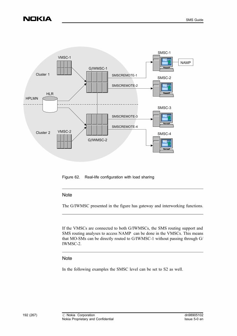
Figure 62. Real-life configuration with load sharing
Note
The G/IWMSC presented in the figure has gateway and interworking functions.
If the VMSCs are connected to both G/IWMSCs, the SMS routing support andSMS routing analyses to access NAMP can be done in the VMSCs. This meansthat MO-SMs can be directly routed to G/IWMSC-1 without passing through G/IWMSC-2.
Note
In the following examples the SMSC level can be set to S2 as well.
VMSC-1
G/IWMSC-1
HLR
G/IWMSC-2
VMSC-2
HPLMN
Cluster 1
Cluster 2
SMSC-2
SMSC-1
SMSC-4
SMSC-3
SMSCREMOTE-1
NAMP
SMSCREMOTE-2
SMSCREMOTE-3
SMSCREMOTE-4
192 (267) # Nokia CorporationNokia Proprietary and Confidential
dn98905102Issue 5-0 en
SMS Guide

In these examples no GT analyses have been defined previously, so when creatingGT analysis with the NAC command the resulting analysis is defined as resultrecord index 1, the next GT analysis is defined as result record index 2, and so on.
You can check whether there are already GT analyses defined in your system withthe NAI command. If yes, the result record index of the GT analyses starts fromthe first free record.
Steps
1. Create global title analyses in the HLR for all physical SMSC ISDNspointing to their own G/IWMSCs (NAC, NBC)
Create global title analyses in the HLR for all physical SMSC ISDNspointing to their own G/IWMSCs.
a. Create a GT for G/IWMSC-1
ZNAC:NET=NA0,DPC=340,RI=GT;
ZNBC:::358400000001:1;
ZNBC:::358400000002:1;
b. Create a GT for G/IWMSC-2
ZNAC:NET=NA0,DPC=341,RI=GT;
ZNBC:::358400000003:2;
ZNBC:::358400000004:2;
2. Group the VMSCs (NAC, NBC)
Group the VMSCs (358411111111 and 358422222222) into two clusters.This grouping (defined for logical number) can be implemented throughGT analyses in a way that the GT analyses for the logical SMSC address inall VMSCs in cluster 1 should point to G/IWMSC-1 and those in cluster 2to G/IWMSC-2.
a. In VMSC-1:
ZNAC:NET=NA0,DPC=340,RI=GT;
ZNBC:::358400000000:1;
b. In VMSC-2:
ZNAC:NET=NA0,DPC=341,RI=GT;
ZNBC:::358400000000:1;
dn98905102Issue 5-0 en
# Nokia CorporationNokia Proprietary and Confidential
193 (267)
Working examples for SMS management
3. Create GT analysis in the G/IWMSCs for the logical SMSC-ISDNpointing to itself (NAC, NBC)
a. In G/IWMSC-1:
ZNAC:NET=NA0,DPC=340,RI=GT;
ZNBC:::358400000000:1;
b. In G/IWMSC-2:
ZNAC:NET=NA0,DPC=341,RI=GT;
ZNBC:::358400000000:1;
4. Create a GT analysis in the G/IWMSC-2 for the physical SMSC-ISDNto route the SMs to NAMP (NAC, NBC)
ZNAC:NET=NA0,DPC=340,RI=GT;
ZNBC:::358400000001:2;
5. Create GT analysis in both G/IWMSCs for the VMSC-ISDN to routeMT-SMs (NAC, NBC)
a. In G/IWMSC-1:
ZNAC:NET=NA0,DPC=301,RI=GT;
ZNBC:::358411111111:2;
b. In G/IWMSC-2:
ZNAC:NET=NA0,DPC=302,RI=GT;
ZNBC:::358422222222:3;
6. Create GT analysis in both VMSCs for the VMSC-ISDNs pointing tothemselves (NAC, NBC)
a. In VMSC-1:
ZNAC:NET=NA0,DPC=301,RI=GT;
ZNBC:::358411111111:2;
b. In VMSC-2:
ZNAC:NET=NA0,DPC=302,RI=GT;
ZNBC:::358422222222:2;
7. Create GT analysis in the G/IWMSCs for the physical SMSCaddresses for Alert SC purposes pointing to themselves (NBC)
194 (267) # Nokia CorporationNokia Proprietary and Confidential
dn98905102Issue 5-0 en
SMS Guide

a. In G/IWMSC-1:
As in Step 3 this GT analysis has already been created, result record1 has to be used.
ZNBC:::358400000001:1;
ZNBC:::358400000002:1;
b. In G/IWMSC-2
As in Step 3 this GT analysis has already been created, result record1 has to be used.
ZNBC:::358400000003:1;
ZNBC:::358400000004:1;
8. Create SMS routing support analysis for the logical SMSC ISDNaddress (CFU)
ZCFU:SMSC=358400000000;
9. Create an SMS routing analysis to access NAMP in both G/IWMSCspointing to the physical SMSC-ISDN connected to NAMP (CFE)
ZCFE:SAP=991,SAPTYPE=NAT:SMSC=358400000001,SAN=NAMP;
Further information:
The execution printout of this command is the following:
CREATING SMS ROUTING ANALYSIS
PID SAP SAPTYPE SMSC ADDRESS TARIFF SERVICE
CLASS APPLICATION NAME
N 991 NAT 358400000001 - NAMP
COMMAND EXECUTED
10. Create SMSC analyses to G/IWMSC-1 (CFS)
ZCFS:358400000000,AEN:LEVEL=S3:ADD:�SMSCREMOTE1�,�SMSCREMOTE2�;
ZCFS:358400000001,AEN:LEVEL=S3:ADD:�SMSCREMOTE1�;
ZCFS:358400000002,AEN:LEVEL=S3:ADD:�SMSCREMOTE2�;
The analyses for the physical addresses (358400000001, 358400000002)are needed for the Alert SC request routing.
dn98905102Issue 5-0 en
# Nokia CorporationNokia Proprietary and Confidential
195 (267)
Working examples for SMS management

Note
In this example the SMSC level can be set to S2 as well.
Expected outcome
The execution printouts of the above commands are the following:
CREATING/MODIFYING SMSC ADDRESS ANALYSIS
NO EXISTING ANALYSIS FOR THIS SMSC ADDRESS FOUND
CREATING SMSC ADDRESS ANALYSIS
SMSC ADDRESS = 358400000000
RESULT = ROUTE SM TO SMSC WITH AEN
SMSC LEVEL = STANDARD PHASE 2+
AENS = SMSCREMOTE1
SMSCREMOTE2
COMMAND EXECUTED
CREATING/MODIFYING SMSC ADDRESS ANALYSIS
NO EXISTING ANALYSIS FOR THIS SMSC ADDRESS FOUND
CREATING SMSC ADDRESS ANALYSIS
SMSC ADDRESS = 358400000001
RESULT = ROUTE SM TO SMSC WITH AEN
SMSC LEVEL = STANDARD PHASE 2+
AENS = SMSCREMOTE1
COMMAND EXECUTED
CREATING/MODIFYING SMSC ADDRESS ANALYSIS
NO EXISTING ANALYSIS FOR THIS SMSC ADDRESS FOUND
CREATING SMSC ADDRESS ANALYSIS
SMSC ADDRESS = 358400000002
RESULT = ROUTE SM TO SMSC WITH AEN
SMSC LEVEL = STANDARD PHASE 2+
AENS = SMSCREMOTE2
COMMAND EXECUTED
Further information:
If you want to check the SMSC address analyses, use the CFI command.
196 (267) # Nokia CorporationNokia Proprietary and Confidential
dn98905102Issue 5-0 en
SMS Guide
ZCFI:TYPE=SMSC;
The example for the execution printout is the following:
SMSC ADDRESS ANALYSES
SMSC ADDRESS = 358400000000
RESULT = ROUTE SM TO SMSC WITH AEN
SMSC LEVEL = STANDARD PHASE 2+
AENS = SMSCREMOTE1
SMSCREMOTE2
SMSC ADDRESS = 358400000001
RESULT = ROUTE SM TO SMSC WITH AEN
SMSC LEVEL = STANDARD PHASE 2+
AENS = SMSCREMOTE1
SMSC ADDRESS = 358400000002
RESULT = ROUTE SM TO SMSC WITH AEN
SMSC LEVEL = STANDARD PHASE 2+
AENS = SMSCREMOTE2
COMMAND EXECUTED
11. Create SMSC analyses to G/IWMSC-2 (CFS)
ZCFS:358400000000,AEN:LEVEL=S3:ADD:�SMSCREMOTE3�,�SMSCREMOTE4�;
ZCFS:358400000003,AEN:LEVEL=S3:ADD:�SMSCREMOTE3�;
ZCFS:358400000004,AEN:LEVEL=S3:ADD:�SMSCREMOTE4�;
Expected outcome
The execution printouts of the commands mentioned above are thefollowing:
CREATING/MODIFYING SMSC ADDRESS ANALYSIS
NO EXISTING ANALYSIS FOR THIS SMSC ADDRESS FOUND
CREATING SMSC ADDRESS ANALYSIS
SMSC ADDRESS = 358400000000
RESULT = ROUTE SM TO SMSC WITH AEN
SMSC LEVEL = STANDARD PHASE 2+
AENS = SMSCREMOTE3
SMSCREMOTE4
COMMAND EXECUTED
CREATING/MODIFYING SMSC ADDRESS ANALYSIS
NO EXISTING ANALYSIS FOR THIS SMSC ADDRESS FOUND
dn98905102Issue 5-0 en
# Nokia CorporationNokia Proprietary and Confidential
197 (267)
Working examples for SMS management
CREATING SMSC ADDRESS ANALYSIS
SMSC ADDRESS = 358400000003
RESULT = ROUTE SM TO SMSC WITH AEN
SMSC LEVEL = STANDARD PHASE 2+
AENS = SMSCREMOTE3
COMMAND EXECUTED
CREATING/MODIFYING SMSC ADDRESS ANALYSIS
NO EXISTING ANALYSIS FOR THIS SMSC ADDRESS FOUND
CREATING SMSC ADDRESS ANALYSIS
SMSC ADDRESS = 358400000004
RESULT = ROUTE SM TO SMSC WITH AEN
SMSC LEVEL = STANDARD PHASE 2+
AENS = SMSCREMOTE4
COMMAND EXECUTED
Further information:
If you want to check the SMSC address analyses, use the CFI command.
ZCFI:TYPE=SMSC;
The example for the execution printout is the following:
SMSC ADDRESS ANALYSES
SMSC ADDRESS = 358400000000
RESULT = ROUTE SM TO SMSC WITH AEN
SMSC LEVEL = STANDARD PHASE 2+
AENS = SMSCREMOTE3
SMSCREMOTE4
SMSC ADDRESS = 358400000003
RESULT = ROUTE SM TO SMSC WITH AEN
SMSC LEVEL = STANDARD PHASE 2+
AENS = SMSCREMOTE3
SMSC ADDRESS = 358400000004
RESULT = ROUTE SM TO SMSC WITH AEN
SMSC LEVEL = STANDARD PHASE 2+
AENS = SMSCREMOTE4
COMMAND EXECUTED
12. Patch UTPFIL in both G/IWMSCs
Patch UTPFIL in both G/IWMSCs, that is, put the logical SMSC-ISDN(358400000000) to UTPFIL.
198 (267) # Nokia CorporationNokia Proprietary and Confidential
dn98905102Issue 5-0 en
SMS Guide
Note
This step is necessary only if you do not have Feature 1165: Short MessageService GSM Phase 2+ Enhancements in your network.
a. Identify the active CM
ZUSI:CM;
b. Find the first free record in CCSU-UTPFIL (= record full of zeros)
ZDFD:CM,x:5AC0007,;
where x is the active CM.
Note
For compact MSCi the UTPFIL number is 5AC01017.
c. Patch the following three records
ZDFS:CM,x:5AC0007,y,;
where x is the active CM and y is the record to be patched.
The new value for the record is: 9D 01 25 00 0C 91 53 48.
ZDFS:CM,x:5AC0007,y+1,;
where x is the active CM and y+1 is the record to be patched.
The new value for the record is: 9D 01 26 00 00 00 00 00.
ZDFS:CM,x:5AC0007,y+2,;
where x is the active CM and y+2 is the record to be patched.
The new value for the record is: 9D 01 27 00 FF FF FF FF.
d. Restart every CCSU unit one by one
The meaning of the record is the following:
Table 11. Explanation of bytes in UTPFIL records
Byte(s) Explanation
9D 01 019D (SMHPRB)
25 00 index in SMHPRB
5th byte in record 1 number length of logical SMSC address (for example, 12 = 0C)
dn98905102Issue 5-0 en
# Nokia CorporationNokia Proprietary and Confidential
199 (267)
Working examples for SMS management
Table 11. Explanation of bytes in UTPFIL records (cont.)
Byte(s) Explanation
6th byte in record 1 number indicator
7th and 8th bytes in record 1 first part of the number (for example, 53 4 8 ==> 3584)
5th - 8th bytes in record 2 continuation of the number (for example, 00 00 00 00 ==>00000000)
5th - 8th bytes in record 3 end of the number (for example, FF FF FF FF)
6.2 Configuring network elements for short messageservices with more MSCs connected to the sameSMSC
This example shows that it is possible to connect more MSCs to the same SMSC .
It shows a possible configuration of network elements for short message serviceswhere the logical SMSC address is 358400000000, the physical SMSC addressesare 358400000001 and 358400000002, the VMSC addresses are 358411111111and 358422222222, the destination point codes of the gateway MSCs are 340 and341 and the destination point codes of the VMSCs are 301 and 302 (see also thefigure below).
200 (267) # Nokia CorporationNokia Proprietary and Confidential
dn98905102Issue 5-0 en
SMS Guide

Figure 63. Real-life configuration with load sharing and more MSCs connectedto the same SMSC
Note
The G/IWMSC presented in the figure has gateway and interworking functions.
In the following examples the SMSC level can be set to S2 as well.
In these examples no GT analyses have been defined previously, therefore whencreating GT analysis with the NAC command, the resulting analysis is defined asresult record index 1, the next GT analysis is defined as result record index 2, andso on.
You can check whether there are already GT analyses defined in your system withthe NAI command. If yes, the result record index of the GT analyses starts fromthe first free record.
VMSC-1
G/IWMSC-1
HLR
G/IWMSC-2
VMSC-2
HPLMN
Cluster 1
Cluster 2
SMSC-1SMSCREMOTE-1
NAMP
SMSC-2
SMSCREMOTE-4
SMSCREMOTE-2
SMSCREMOTE-3
dn98905102Issue 5-0 en
# Nokia CorporationNokia Proprietary and Confidential
201 (267)
Working examples for SMS management

Steps
1. Create global title analyses in the HLR for the physical SMSC ISDNspointing to their own G/IWMSCs (NAC, NBC)
a. Create a global title translation result
ZNAC:NET=NA0,DPC=340,RI=GT;
b. Create global title analyses
ZNBC:::358400000001:1;
ZNBC:::358400000002:1;
2. Group the VMSCs (NAC, NBC)
Group the VMSCs (358411111111 and 358422222222) into two clusters.This grouping (defined for logical number) can be implemented throughGT analyses in a way that the GT analyses in the VMSC in cluster 1 shouldpoint to G/IWMSC 1 and that in cluster 2 to G/IWMSC 2.
a. In VMSC-1:
ZNAC:NET=NA0,DPC=340,RI=GT;
ZNBC:::358400000000:1;
b. In VMSC-2:
ZNAC:NET=NA0,DPC=341,RI=GT;
ZNBC:::358400000000:1;
3. Create GT analysis in the G/IWMSCs for the logical SC-ISDNpointing to themselves (NAC, NBC)
a. In G/IWMSC-1:
ZNAC:NET=NA0,DPC=340,RI=GT;
ZNBC:::358400000000:1;
b. In G/IWMSC-2:
ZNAC:NET=NA0,DPC=341,RI=GT;
ZNBC:::358400000000:1;
4. Create GT analysis in G/IWMSC�1 (NBC)
Create GT analysis in G/IWMSC�1 for the physical SMSC addressespoiting to itself for Alert SC purposes.
As this GT analysis has already been created in the previous step, resultrecord 1 has to be used.
202 (267) # Nokia CorporationNokia Proprietary and Confidential
dn98905102Issue 5-0 en
SMS Guide
ZNBC:::358400000001:1;
ZNBC:::358400000002:1;
5. Create GT analysis in both G/IWMSCs (NAC, NBC)
Create GT analysis in both G/IWMSCs for the VMSC-ISDNs to route MT-SMs.
a. In G/IWMSC-1:
ZNAC:NET=NA0,DPC=301,RI=GT;
ZNBC:::358411111111:2;
b. In G/IWMSC-2:
ZNAC:NET=NA0,DPC=302,RI=GT;
ZNBC:::358422222222:2;
6. Create GT analysis in both VMSCs for the VMSC-ISDNs pointing tothemselves (NAC, NBC)
a. In VMSC-1:
ZNAC:NET=NA0,DPC=301,RI=GT;
ZNBC:::358411111111:2;
b. In VMSC-2:
ZNAC:NET=NA0,DPC=302,RI=GT;
ZNBC:::358422222222:2;
7. Create SMS routing support analysis for logical SMSC ISDN address(CFU)
ZCFU:SMSC=358400000000;
8. Create an SMS routing analysis to access NAMP (CFE)
Create an SMS routing analysis to access NAMP in both G/IWMSCspoiting to the physical SMSC-ISDN connected to NAMP.
ZCFE:SAP=991,SAPTYPE=NAT:SMSC=358400000001,SAN=NAMP;
Expected outcome
The execution printout of this command is the following:
dn98905102Issue 5-0 en
# Nokia CorporationNokia Proprietary and Confidential
203 (267)
Working examples for SMS management
CREATING SMS ROUTING ANALYSIS
PID SAP SAPTYPE SMSC ADDRESS TARIFF SERVICE
CLASS APPLICATION NAME
N 991 NAT 358400000001 - NAMP
COMMAND EXECUTED
9. Create SC analyses to G/IWMSC-1 (CFS)
ZCFS:358400000000,AEN:LEVEL=S2:ADD:�SMSCREMOTE1�,�SMSCREMOTE2�;
ZCFS:358400000001,AEN:LEVEL=S3:ADD:�SMSCREMOTE1�;
ZCFS:358400000002,AEN:LEVEL=S3:ADD:�SMSCREMOTE2�;
The analyses for the physical addresses (358400000001, 358400000002)are needed for the Alert SC request routing.
Note
In this example the SMSC level can be set to S2 as well.
Expected outcome
The execution printouts of the above commands are the following:
CREATING/MODIFYING SMSC ADDRESS ANALYSIS
NO EXISTING ANALYSIS FOR THIS SMSC ADDRESS FOUND
CREATING SMSC ADDRESS ANALYSIS
SMSC ADDRESS = 358400000000
RESULT = ROUTE SM TO SMSC WITH AEN
SMSC LEVEL = STANDARD PHASE 2+
AENS = SMSCREMOTE1
SMSCREMOTE2
COMMAND EXECUTED
CREATING/MODIFYING SMSC ADDRESS ANALYSIS
NO EXISTING ANALYSIS FOR THIS SMSC ADDRESS FOUND
204 (267) # Nokia CorporationNokia Proprietary and Confidential
dn98905102Issue 5-0 en
SMS Guide
CREATING SMSC ADDRESS ANALYSIS
SMSC ADDRESS = 358400000001
RESULT = ROUTE SM TO SMSC WITH AEN
SMSC LEVEL = STANDARD PHASE 2+
AENS = SMSCREMOTE1
COMMAND EXECUTED
CREATING/MODIFYING SMSC ADDRESS ANALYSIS
NO EXISTING ANALYSIS FOR THIS SMSC ADDRESS FOUND
CREATING SMSC ADDRESS ANALYSIS
SMSC ADDRESS = 358400000002
RESULT = ROUTE SM TO SMSC WITH AEN
SMSC LEVEL = STANDARD PHASE 2+
AENS = SMSCREMOTE2
COMMAND EXECUTED
Further information:
If you want to check the SMSC address analyses, use the CFI command.
ZCFI:TYPE=SMSC;
The example for the execution printout is the following:
SMSC ADDRESS ANALYSES
SMSC ADDRESS = 358400000000
RESULT = ROUTE SM TO SMSC WITH AEN
SMSC LEVEL = STANDARD PHASE 2+
AENS = SMSCREMOTE1
SMSCREMOTE2
SMSC ADDRESS = 358400000001
RESULT = ROUTE SM TO SMSC WITH AEN
SMSC LEVEL = STANDARD PHASE 2+
AENS = SMSCREMOTE1
SMSC ADDRESS = 358400000002
RESULT = ROUTE SM TO SMSC WITH AEN
SMSC LEVEL = STANDARD PHASE 2+
AENS = SMSCREMOTE2
COMMAND EXECUTED
10. Create SMSC analyses to G/IWMSC-2 (CFS)
ZCFS:358400000000,AEN:LEVEL=S3:ADD:�SMSCREMOTE3�,�SMSCREMOTE4�;
dn98905102Issue 5-0 en
# Nokia CorporationNokia Proprietary and Confidential
205 (267)
Working examples for SMS management

ZCFS:358400000001,AEN:LEVEL=S3:ADD:�SMSCREMOTE3�;
Expected outcome
The execution printouts of these commands are the following:
CREATING/MODIFYING SMSC ADDRESS ANALYSIS
NO EXISTING ANALYSIS FOR THIS SMSC ADDRESS FOUND
CREATING SMSC ADDRESS ANALYSIS
SMSC ADDRESS = 358400000000
RESULT = ROUTE SM TO SMSC WITH AEN
SMSC LEVEL = STANDARD PHASE 2+
AENS = SMSCREMOTE3
SMSCREMOTE4
COMMAND EXECUTED
CREATING/MODIFYING SMSC ADDRESS ANALYSIS
NO EXISTING ANALYSIS FOR THIS SMSC ADDRESS FOUND
CREATING SMSC ADDRESS ANALYSIS
SMSC ADDRESS = 358400000001
RESULT = ROUTE SM TO SMSC WITH AEN
SMSC LEVEL = STANDARD PHASE 2+
AENS = SMSCREMOTE3
COMMAND EXECUTED
Further information:
If you want to check the SMSC address analyses, use the CFI command.
ZCFI:TYPE=SMSC;
The example for the execution printout is the following:
SMSC ADDRESS ANALYSES
SMSC ADDRESS = 358400000000
RESULT = ROUTE SM TO SMSC WITH AEN
SMSC LEVEL = STANDARD PHASE 2+
AENS = SMSCREMOTE3
SMSCREMOTE4
SMSC ADDRESS = 358400000001
RESULT = ROUTE SM TO SMSC WITH AEN
SMSC LEVEL = STANDARD PHASE 2+
AENS = SMSCREMOTE3
COMMAND EXECUTED
206 (267) # Nokia CorporationNokia Proprietary and Confidential
dn98905102Issue 5-0 en
SMS Guide
11. Patch UTPFIL in both G/IWMSCs
Patch UTPFIL in both G/IWMSCs, that is, put the logical SMSC-ISDN(358400000000) to UTPFIL.
Note
This step is necessary only if you do not have Feature 1165: Short MessageServices GSM Phase 2+ Enhancements in use in your network.
a. Identify the active CM
ZUSI:CM;
b. Find the first free record in CCSU-UTPFIL (= record full of zeros)
ZDFD:CM,x:5AC0007,;
where x is the active CM.
Note
For compact MSCi the UTPFIL number is 5AC01017.
c. Patch the following three records
ZDFS:CM,x:5AC0007,y,;
where x is the active CM and y is the record to be patched.
The new value for the record is: 9D 01 25 00 0C 91 53 48.
ZDFS:CM,x:5AC0007,y+1,;
where x is the active CM and y+1 is the record to be patched.
The new value for the record is: 9D 01 26 00 00 00 00 00.
ZDFS:CM,x:5AC0007,y+2,;
where x is the active CM and y+2 is the record to be patched.
The new value for the record is: 9D 01 27 00 FF FF FF FF.
You can find the meaning of the record in Table Explanation ofbytes in UTPFIL records .
d. Restart every CCSU unit one by one
dn98905102Issue 5-0 en
# Nokia CorporationNokia Proprietary and Confidential
207 (267)
Working examples for SMS management
6.3 Configuring network elements for SMS with loadsharing of SMSC clusters when the traffic categoryis normal traffic
In this example a real configuration is described with TCP/IP interface betweenthe network elements. The main difference between this example and the examplegiven for Configuring network elements for short message services with loadsharing, is the way in which the G/IWMSC and the SMSC are connected. Toutilise most effectively this interface and reach full redundancy, it isrecommended to utilize 2 BDCUs (do not necessarily be dedicated to SMS) in theMSC and create two LAN connections between MSC and SMSC and use 2 IPaddresses for one SMSC.
Note
It is not allowed to connect SMSC(s) having the same IP address to one MSC.
The example shows a possible configuration of network elements for shortmessage services where the logical SMSC address is 358400000000, the physicalSMSC addresses are 358400000001, 358400000002, 358400000003,358400000004, 358400000005, and 358400000006, the VMSC addresses are358411111111 and 358422222222, the destination point codes of the gatewayMSCs are 340 and 341, and the destination point codes of the VMSCs are 301and 302 (see also the figure below).
208 (267) # Nokia CorporationNokia Proprietary and Confidential
dn98905102Issue 5-0 en
SMS Guide
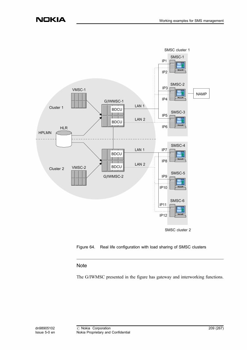
Figure 64. Real life configuration with load sharing of SMSC clusters
Note
The G/IWMSC presented in the figure has gateway and interworking functions.
VMSC-1
G/IWMSC-1
HLR
G/IWMSC-2
VMSC-2
HPLMN
Cluster 1
Cluster 2
SMSC-3
SMSC-2
SMSC-1
LAN 1
LAN 2
SMSC cluster 1
SMSC-5
SMSC-4
SMSC-6
LAN 1
LAN 2
SMSC cluster 2
BDCU
IP1
IP2
IP3
IP4
IP5
IP6
IP7
IP8
IP9
IP10
IP11
IP12
NAMP
BDCU
BDCU
BDCU
dn98905102Issue 5-0 en
# Nokia CorporationNokia Proprietary and Confidential
209 (267)
Working examples for SMS management

In these examples no GT analyses have been defined previously, so when creatingGT analysis with the NAC command, the resulting analysis is defined as resultrecord index 1, the next GT analysis is defined as result record index 2, and so on.
You can check whether there are already GT analyses defined in your system withthe NAI command. If yes, the result record index of the GT analyses starts fromthe first free record.
Steps
1. Create global title analyses in the HLR for the physical SMSC ISDNspointing to their own G/IWMSC (NAC, NBC)
a. Create a GT for G/IWMSC-1:
ZNAC:NET=NA0,DPC=340,RI=GT;
ZNBC:::358400000001:1;
ZNBC:::358400000002:1;
ZNBC:::358400000003:1;
b. Create a GT for G/IWMSC-2:
ZNAC:NET=NA0,DPC=341,RI=GT;
ZNBC:::358400000004:2;
ZNBC:::358400000005:2;
ZNBC:::358400000006:2;
2. Group the VMSCs (NAC, NBC)
Group the VMSCs (358411111111 and 358422222222) into two clusters.This grouping (defined for logical number) can be implemented throughGT analyses in a way that the GT analyses for the logical SMSC address inall VMSCs in cluster 1 should point to G/IWMSC-1 and those in cluster 2to G/IWMSC-2.
a. In VMSC-1:
ZNAC:NET=NA0,DPC=340,RI=GT;
ZNBC:::358400000000:1;
b. In VMSC-2:
ZNAC:NET=NA0,DPC=341,RI=GT;
ZNBC:::358400000000:1;
210 (267) # Nokia CorporationNokia Proprietary and Confidential
dn98905102Issue 5-0 en
SMS Guide
3. Create GT analysis in both G/IWMSCs for the logical SMSC-ISDNpointing to themselves (NAC, NBC)
a. In G/IWMSC-1:
ZNAC:NET=NA0,DPC=340,RI=GT;
ZNBC:::358400000000:1;
b. In G/IWMSC-2:
ZNAC:NET=NA0,DPC=341,RI=GT;
ZNBC:::358400000000:1;
4. Create a GT analysis in the G/IWMSC-2 for the physical SMSC-ISDNto route the SMs to NAMP (NAC, NBC)
ZNAC:NET=NA0,DPC=340,RI=GT;
ZNBC:::358400000111:2;
5. Create a GT analysis in G/IWMSC-1 for the physical SMSC-ISDN forNAMP pointing to itself (NBC)
As this GT analysis has already been created in step 3 in the G/IWMSC-1result record 1 has to be used.
ZNBC:::358400000111:1;
6. Create GT analysis in both G/IWMSCs (NAC, NBC)
Create GT analysis in both G/IWMSCs for the VMSC-ISDNs to route theMT-SMs.
a. In G/IWMSC-1:
ZNAC:NET=NA0,DPC=301,RI=GT;
ZNBC:::358411111111:2;
b. In G/IWMSC-2:
ZNAC:NET=NA0,DPC=302,RI=GT;
ZNBC:::358422222222:3;
7. Create GT analysis in both VMSCs for VMSC-ISDNs pointing tothemselves (NAC, NBC)
a. In VMSC-1:
ZNAC:NET=NA0,DPC=301,RI=GT;
dn98905102Issue 5-0 en
# Nokia CorporationNokia Proprietary and Confidential
211 (267)
Working examples for SMS management

ZNBC:::358411111111:2;
b. In VMSC-2:
ZNAC:NET=NA0,DPC=302,RI=GT;
ZNBC:::358422222222:2;
8. Create GT analyses in the G/IWMSCs (NBC)
Create GT analyses in the G/IWMSCs for the physical SMSC addresses forAlert SC purposes pointing to themselves.
a. In G/IWMSC-1:
As this GT analysis has already been created in step 3 result record 1has to be used.
ZNBC:::358400000001:1;
ZNBC:::358400000002:1;
ZNBC:::358400000003:1;
b. In G/IWMSC-2:
As this GT analysis has already been created in step 3 result record 1has to be used.
ZNBC:::358400000004:1;
ZNBC:::358400000005:1;
ZNBC:::358400000006:1;
9. Create SMS routing support analysis for logical SMSC ISDN address(CFU)
ZCFU:SMSC=358400000000;
10. Create an SMS routing analysis to access NAMP (CFE)
Create an SMS routing analysis to access NAMP in both G/IWMSCspointing to the physical SMSC-ISDN connected to NAMP.
ZCFE:SAP=991,SAPTYPE=NAT:SMSC=358400000111,SAN=NAMP;
Expected outcome
The execution printout of this command is the following:
CREATING SMS ROUTING ANALYSIS
212 (267) # Nokia CorporationNokia Proprietary and Confidential
dn98905102Issue 5-0 en
SMS Guide

PID SAP SAPTYPE SMSC ADDRESS TARIFF SERVICE
CLASS APPLICATION NAME
N 991 NAT 358400000111 - NAMP
COMMAND EXECUTED
11. Create SC analyses to G/IWMSC-1 (CFS)
ZCFS:358400000000,IP:LEVEL=S3,PASSW=PASSWORD:ADD:�IP1�,�IP2�,�IP3�,�IP4�,�IP5�,�IP6�,;
Create SMSC analyses for IP addresses one by one like this:
ZCFS:358400000000,IP:LEVEL=S3,PASSW=PASSWORD:ADD:�IP1�,;
ZCFS:358400000000,IP:LEVEL=S3,PASSW=PASSWORD:ADD:�IP2�,;
ZCFS:358400000000,IP:LEVEL=S3,PASSW=PASSWORD:ADD:�IP3�,;
and so on.
Confirm each command execution.
ZCFS:358400000111,IP:LEVEL=S3,PASSW=PASSWORD:ADD:�IP3� ;
ZCFS:358400000111,IP:LEVEL=S3:ADD:�IP4�;
ZCFS:358400000001,IP:LEVEL=S3,PASSW=PASSWORD:ADD:�IP1�;
ZCFS:358400000001,IP:LEVEL=S3:ADD:�IP2�;
ZCFS:358400000002,IP:LEVEL=S3,PASSW=PASSWORD:ADD:�IP3�;
ZCFS:358400000002,IP:LEVEL=S3:ADD:�IP4�;
ZCFS:358400000003,IP:LEVEL=S3,PASSW=PASSWORD:ADD:�IP5�;
dn98905102Issue 5-0 en
# Nokia CorporationNokia Proprietary and Confidential
213 (267)
Working examples for SMS management
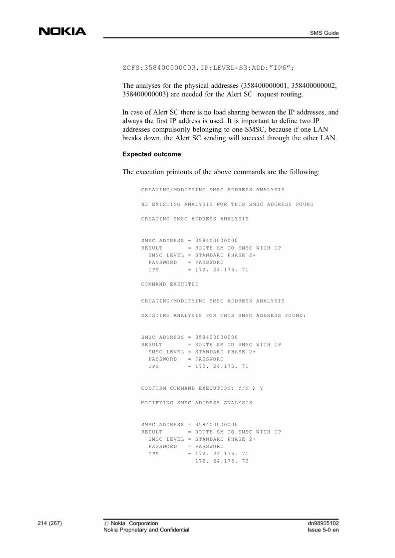
ZCFS:358400000003,IP:LEVEL=S3:ADD:�IP6�;
The analyses for the physical addresses (358400000001, 358400000002,358400000003) are needed for the Alert SC request routing.
In case of Alert SC there is no load sharing between the IP addresses, andalways the first IP address is used. It is important to define two IPaddresses compulsorily belonging to one SMSC, because if one LANbreaks down, the Alert SC sending will succeed through the other LAN.
Expected outcome
The execution printouts of the above commands are the following:
CREATING/MODIFYING SMSC ADDRESS ANALYSIS
NO EXISTING ANALYSIS FOR THIS SMSC ADDRESS FOUND
CREATING SMSC ADDRESS ANALYSIS
SMSC ADDRESS = 358400000000
RESULT = ROUTE SM TO SMSC WITH IP
SMSC LEVEL = STANDARD PHASE 2+
PASSWORD = PASSWORD
IPS = 172. 24.175. 71
COMMAND EXECUTED
CREATING/MODIFYING SMSC ADDRESS ANALYSIS
EXISTING ANALYSIS FOR THIS SMSC ADDRESS FOUND:
SMSC ADDRESS = 358400000000
RESULT = ROUTE SM TO SMSC WITH IP
SMSC LEVEL = STANDARD PHASE 2+
PASSWORD = PASSWORD
IPS = 172. 24.175. 71
CONFIRM COMMAND EXECUTION: Y/N ? Y
MODIFYING SMSC ADDRESS ANALYSIS
SMSC ADDRESS = 358400000000
RESULT = ROUTE SM TO SMSC WITH IP
SMSC LEVEL = STANDARD PHASE 2+
PASSWORD = PASSWORD
IPS = 172. 24.175. 71
172. 24.175. 72
214 (267) # Nokia CorporationNokia Proprietary and Confidential
dn98905102Issue 5-0 en
SMS Guide

COMMAND EXECUTED
CREATING/MODIFYING SMSC ADDRESS ANALYSIS
EXISTING ANALYSIS FOR THIS SMSC ADDRESS FOUND:
SMSC ADDRESS = 358400000000
RESULT = ROUTE SM TO SMSC WITH IP
SMSC LEVEL = STANDARD PHASE 2+
PASSWORD = PASSWORD
IPS = 172. 24.175. 71
172. 24.175. 72
CONFIRM COMMAND EXECUTION: Y/N ? Y
MODIFYING SMSC ADDRESS ANALYSIS
SMSC ADDRESS = 358400000000
RESULT = ROUTE SM TO SMSC WITH IP
SMSC LEVEL = STANDARD PHASE 2+
PASSWORD = PASSWORD
IPS = 172. 24.175. 71
172. 24.175. 72
172. 24.175. 73
COMMAND EXECUTED
CREATING/MODIFYING SMSC ADDRESS ANALYSIS
EXISTING ANALYSIS FOR THIS SMSC ADDRESS FOUND:
SMSC ADDRESS = 358400000000
RESULT = ROUTE SM TO SMSC WITH IP
SMSC LEVEL = STANDARD PHASE 2+
PASSWORD = PASSWORD
IPS = 172. 24.175. 71
172. 24.175. 72
172. 24.175. 73
CONFIRM COMMAND EXECUTION: Y/N ? Y
MODIFYING SMSC ADDRESS ANALYSIS
SMSC ADDRESS = 358400000000
RESULT = ROUTE SM TO SMSC WITH IP
SMSC LEVEL = STANDARD PHASE 2+
PASSWORD = PASSWORD
IPS = 172. 24.175. 71
172. 24.175. 72
dn98905102Issue 5-0 en
# Nokia CorporationNokia Proprietary and Confidential
215 (267)
Working examples for SMS management
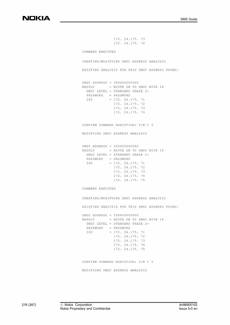
172. 24.175. 73
172. 24.175. 74
COMMAND EXECUTED
CREATING/MODIFYING SMSC ADDRESS ANALYSIS
EXISTING ANALYSIS FOR THIS SMSC ADDRESS FOUND:
SMSC ADDRESS = 358400000000
RESULT = ROUTE SM TO SMSC WITH IP
SMSC LEVEL = STANDARD PHASE 2+
PASSWORD = PASSWORD
IPS = 172. 24.175. 71
172. 24.175. 72
172. 24.175. 73
172. 24.175. 74
CONFIRM COMMAND EXECUTION: Y/N ? Y
MODIFYING SMSC ADDRESS ANALYSIS
SMSC ADDRESS = 358400000000
RESULT = ROUTE SM TO SMSC WITH IP
SMSC LEVEL = STANDARD PHASE 2+
PASSWORD = PASSWORD
IPS = 172. 24.175. 71
172. 24.175. 72
172. 24.175. 73
172. 24.175. 74
172. 24.175. 75
COMMAND EXECUTED
CREATING/MODIFYING SMSC ADDRESS ANALYSIS
EXISTING ANALYSIS FOR THIS SMSC ADDRESS FOUND:
SMSC ADDRESS = 358400000000
RESULT = ROUTE SM TO SMSC WITH IP
SMSC LEVEL = STANDARD PHASE 2+
PASSWORD = PASSWORD
IPS = 172. 24.175. 71
172. 24.175. 72
172. 24.175. 73
172. 24.175. 74
172. 24.175. 75
CONFIRM COMMAND EXECUTION: Y/N ? Y
MODIFYING SMSC ADDRESS ANALYSIS
216 (267) # Nokia CorporationNokia Proprietary and Confidential
dn98905102Issue 5-0 en
SMS Guide

SMSC ADDRESS = 358400000000
RESULT = ROUTE SM TO SMSC WITH IP
SMSC LEVEL = STANDARD PHASE 2+
PASSWORD = PASSWORD
IPS = 172. 24.175. 71
172. 24.175. 72
172. 24.175. 73
172. 24.175. 74
172. 24.175. 75
172. 24.175. 76
COMMAND EXECUTED
CREATING/MODIFYING SMSC ADDRESS ANALYSIS
NO EXISTING ANALYSIS FOR THIS SMSC ADDRESS FOUND
CREATING SMSC ADDRESS ANALYSIS
SMSC ADDRESS = 358400000111
RESULT = ROUTE SM TO SMSC WITH IP
SMSC LEVEL = STANDARD PHASE 2+
PASSWORD = PASSWORD
IPS = 172. 24.175. 73
COMMAND EXECUTED
CREATING/MODIFYING SMSC ADDRESS ANALYSIS
EXISTING ANALYSIS FOR THIS SMSC ADDRESS FOUND:
SMSC ADDRESS = 358400000111
RESULT = ROUTE SM TO SMSC WITH IP
SMSC LEVEL = STANDARD PHASE 2+
PASSWORD = PASSWORD
IPS = 172. 24.175. 73
CONFIRM COMMAND EXECUTION: Y/N ? Y
MODIFYING SMSC ADDRESS ANALYSIS
SMSC ADDRESS = 358400000111
RESULT = ROUTE SM TO SMSC WITH IP
SMSC LEVEL = STANDARD PHASE 2+
PASSWORD = PASSWORD
IPS = 172. 24.175. 73
172. 24.175. 74
COMMAND EXECUTED
dn98905102Issue 5-0 en
# Nokia CorporationNokia Proprietary and Confidential
217 (267)
Working examples for SMS management

CREATING/MODIFYING SMSC ADDRESS ANALYSIS
NO EXISTING ANALYSIS FOR THIS SMSC ADDRESS FOUND
CREATING SMSC ADDRESS ANALYSIS
SMSC ADDRESS = 358400000001
RESULT = ROUTE SM TO SMSC WITH IP
SMSC LEVEL = STANDARD PHASE 2+
PASSWORD = PASSWORD
IPS = 172. 24.175. 71
COMMAND EXECUTED
CREATING/MODIFYING SMSC ADDRESS ANALYSIS
EXISTING ANALYSIS FOR THIS SMSC ADDRESS FOUND:
SMSC ADDRESS = 358400000001
RESULT = ROUTE SM TO SMSC WITH IP
SMSC LEVEL = STANDARD PHASE 2+
PASSWORD = PASSWORD
IPS = 172. 24.175. 71
CONFIRM COMMAND EXECUTION: Y/N ? Y
MODIFYING SMSC ADDRESS ANALYSIS
SMSC ADDRESS = 358400000001
RESULT = ROUTE SM TO SMSC WITH IP
SMSC LEVEL = STANDARD PHASE 2+
PASSWORD = PASSWORD
IPS = 172. 24.175. 71
172. 24.175. 72
COMMAND EXECUTED
CREATING/MODIFYING SMSC ADDRESS ANALYSIS
NO EXISTING ANALYSIS FOR THIS SMSC ADDRESS FOUND
CREATING SMSC ADDRESS ANALYSIS
SMSC ADDRESS = 358400000002
RESULT = ROUTE SM TO SMSC WITH IP
SMSC LEVEL = STANDARD PHASE 2+
218 (267) # Nokia CorporationNokia Proprietary and Confidential
dn98905102Issue 5-0 en
SMS Guide

PASSWORD = PASSWORD
IPS = 172. 24.175. 73
COMMAND EXECUTED
CREATING/MODIFYING SMSC ADDRESS ANALYSIS
EXISTING ANALYSIS FOR THIS SMSC ADDRESS FOUND:
SMSC ADDRESS = 358400000002
RESULT = ROUTE SM TO SMSC WITH IP
SMSC LEVEL = STANDARD PHASE 2+
PASSWORD = PASSWORD
IPS = 172. 24.175. 73
CONFIRM COMMAND EXECUTION: Y/N ? Y
MODIFYING SMSC ADDRESS ANALYSIS
SMSC ADDRESS = 358400000002
RESULT = ROUTE SM TO SMSC WITH IP
SMSC LEVEL = STANDARD PHASE 2+
PASSWORD = PASSWORD
IPS = 172. 24.175. 73
172. 24.175. 74
COMMAND EXECUTED
CREATING/MODIFYING SMSC ADDRESS ANALYSIS
NO EXISTING ANALYSIS FOR THIS SMSC ADDRESS FOUND
CREATING SMSC ADDRESS ANALYSIS
SMSC ADDRESS = 358400000003
RESULT = ROUTE SM TO SMSC WITH IP
SMSC LEVEL = STANDARD PHASE 2+
PASSWORD = PASSWORD
IPS = 172. 24.175. 75
COMMAND EXECUTED
CREATING/MODIFYING SMSC ADDRESS ANALYSIS
EXISTING ANALYSIS FOR THIS SMSC ADDRESS FOUND:
SMSC ADDRESS = 358400000003
dn98905102Issue 5-0 en
# Nokia CorporationNokia Proprietary and Confidential
219 (267)
Working examples for SMS management

RESULT = ROUTE SM TO SMSC WITH IP
SMSC LEVEL = STANDARD PHASE 2+
PASSWORD = PASSWORD
IPS = 172. 24.175. 75
CONFIRM COMMAND EXECUTION: Y/N ? Y
MODIFYING SMSC ADDRESS ANALYSIS
SMSC ADDRESS = 358400000003
RESULT = ROUTE SM TO SMSC WITH IP
SMSC LEVEL = STANDARD PHASE 2+
PASSWORD = PASSWORD
IPS = 172. 24.175. 75
172. 24.175. 76
COMMAND EXECUTED
Further information:
If you want to check the SMSC address analyses, use the CFI command.
ZCFI:TYPE=SMSC;
The execution printout should look like this:
SMSC ADDRESS ANALYSES
SMSC ADDRESS = 358400000001
RESULT = ROUTE SM TO SMSC WITH IP
SMSC LEVEL = STANDARD PHASE 2+
PASSWORD = PASSWORD
IPS = 172. 24.175. 71
172. 24.175. 72
SMSC ADDRESS = 358400000002
RESULT = ROUTE SM TO SMSC WITH IP
SMSC LEVEL = STANDARD PHASE 2+
PASSWORD = PASSWORD
IPS = 172. 24.175. 73
172. 24.175. 74
SMSC ADDRESS = 358400000003
RESULT = ROUTE SM TO SMSC WITH IP
SMSC LEVEL = STANDARD PHASE 2+
PASSWORD = PASSWORD
IPS = 172. 24.175. 75
172. 24.175. 76
SMSC ADDRESS = 358400000111
RESULT = ROUTE SM TO SMSC WITH IP
SMSC LEVEL = STANDARD PHASE 2+
PASSWORD = PASSWORD
IPS = 172. 24.175. 73
172. 24.175. 74
SMSC ADDRESS = 358400000000
220 (267) # Nokia CorporationNokia Proprietary and Confidential
dn98905102Issue 5-0 en
SMS Guide

RESULT = ROUTE SM TO SMSC WITH IP
SMSC LEVEL = STANDARD PHASE 2+
PASSWORD = PASSWORD
IPS = 172. 24.175. 71
172. 24.175. 72
172. 24.175. 73
172. 24.175. 74
172. 24.175. 75
172. 24.175. 76
COMMAND EXECUTED
12. Create SMSC analyses to G/IWMSC-2 (CFS)
ZCFS:358400000000,IP:LEVEL=S3,PASSW=<PASSWORD>:ADD:�IP7�,�IP8�,�IP9�,�IP10�,�IP11�,�IP12�;
Create SMSC analyses for IP addresses one by one like in the previousstep. Then confirm each command execution.
ZCFS:358400000004,IP:LEVEL=S3,PASSW=PASSWORD:ADD:�IP7�;
ZCFS:358400000004,IP:LEVEL=S3:ADD:�IP8�;
ZCFS:358400000005,IP:LEVEL=S3,PASSW=PASSWORD:ADD:�IP9�;
ZCFS:358400000005,IP:LEVEL=S3:ADD:�IP10�;
ZCFS:358400000006,IP:LEVEL=S3,PASSW=PASSWORD:ADD:�IP11�;
ZCFS:358400000006,IP:LEVEL=S3:ADD:�IP12�;
Expected outcome
The execution printouts of these commands are the following:
CREATING/MODIFYING SMSC ADDRESS ANALYSIS
NO EXISTING ANALYSIS FOR THIS SMSC ADDRESS FOUND
CREATING SMSC ADDRESS ANALYSIS
SMSC ADDRESS = 358400000000
RESULT = ROUTE SM TO SMSC WITH IP
SMSC LEVEL = STANDARD PHASE 2+
dn98905102Issue 5-0 en
# Nokia CorporationNokia Proprietary and Confidential
221 (267)
Working examples for SMS management
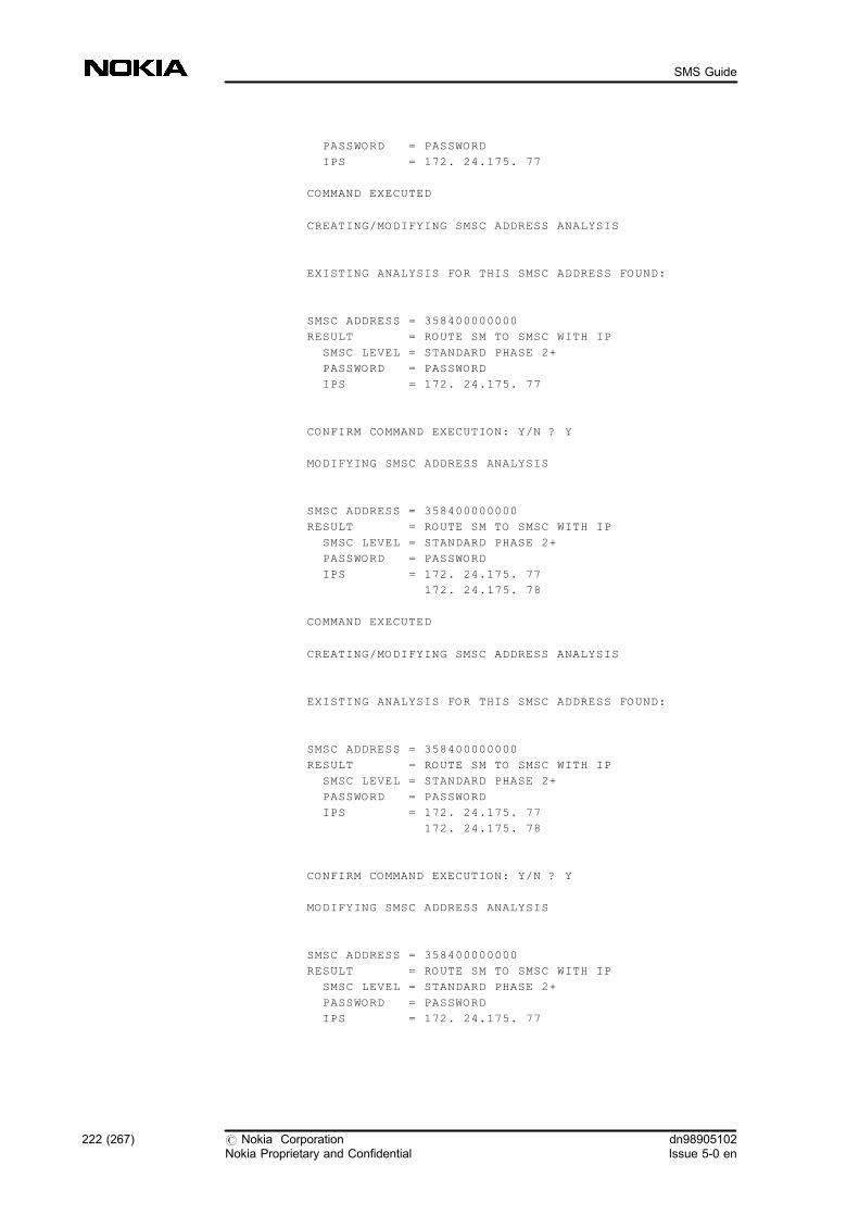
PASSWORD = PASSWORD
IPS = 172. 24.175. 77
COMMAND EXECUTED
CREATING/MODIFYING SMSC ADDRESS ANALYSIS
EXISTING ANALYSIS FOR THIS SMSC ADDRESS FOUND:
SMSC ADDRESS = 358400000000
RESULT = ROUTE SM TO SMSC WITH IP
SMSC LEVEL = STANDARD PHASE 2+
PASSWORD = PASSWORD
IPS = 172. 24.175. 77
CONFIRM COMMAND EXECUTION: Y/N ? Y
MODIFYING SMSC ADDRESS ANALYSIS
SMSC ADDRESS = 358400000000
RESULT = ROUTE SM TO SMSC WITH IP
SMSC LEVEL = STANDARD PHASE 2+
PASSWORD = PASSWORD
IPS = 172. 24.175. 77
172. 24.175. 78
COMMAND EXECUTED
CREATING/MODIFYING SMSC ADDRESS ANALYSIS
EXISTING ANALYSIS FOR THIS SMSC ADDRESS FOUND:
SMSC ADDRESS = 358400000000
RESULT = ROUTE SM TO SMSC WITH IP
SMSC LEVEL = STANDARD PHASE 2+
PASSWORD = PASSWORD
IPS = 172. 24.175. 77
172. 24.175. 78
CONFIRM COMMAND EXECUTION: Y/N ? Y
MODIFYING SMSC ADDRESS ANALYSIS
SMSC ADDRESS = 358400000000
RESULT = ROUTE SM TO SMSC WITH IP
SMSC LEVEL = STANDARD PHASE 2+
PASSWORD = PASSWORD
IPS = 172. 24.175. 77
222 (267) # Nokia CorporationNokia Proprietary and Confidential
dn98905102Issue 5-0 en
SMS Guide

172. 24.175. 78
172. 24.175. 79
COMMAND EXECUTED
CREATING/MODIFYING SMSC ADDRESS ANALYSIS
EXISTING ANALYSIS FOR THIS SMSC ADDRESS FOUND:
SMSC ADDRESS = 358400000000
RESULT = ROUTE SM TO SMSC WITH IP
SMSC LEVEL = STANDARD PHASE 2+
PASSWORD = PASSWORD
IPS = 172. 24.175. 77
172. 24.175. 78
172. 24.175. 79
CONFIRM COMMAND EXECUTION: Y/N ? Y
MODIFYING SMSC ADDRESS ANALYSIS
SMSC ADDRESS = 358400000000
RESULT = ROUTE SM TO SMSC WITH IP
SMSC LEVEL = STANDARD PHASE 2+
PASSWORD = PASSWORD
IPS = 172. 24.175. 77
172. 24.175. 78
172. 24.175. 79
172. 24.175. 80
COMMAND EXECUTED
CREATING/MODIFYING SMSC ADDRESS ANALYSIS
EXISTING ANALYSIS FOR THIS SMSC ADDRESS FOUND:
SMSC ADDRESS = 358400000000
RESULT = ROUTE SM TO SMSC WITH IP
SMSC LEVEL = STANDARD PHASE 2+
PASSWORD = PASSWORD
IPS = 172. 24.175. 77
172. 24.175. 78
172. 24.175. 79
172. 24.175. 80
CONFIRM COMMAND EXECUTION: Y/N ? Y
MODIFYING SMSC ADDRESS ANALYSIS
dn98905102Issue 5-0 en
# Nokia CorporationNokia Proprietary and Confidential
223 (267)
Working examples for SMS management
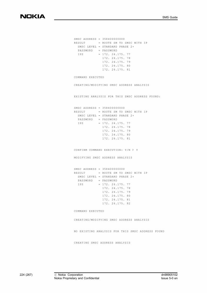
SMSC ADDRESS = 358400000000
RESULT = ROUTE SM TO SMSC WITH IP
SMSC LEVEL = STANDARD PHASE 2+
PASSWORD = PASSWORD
IPS = 172. 24.175. 77
172. 24.175. 78
172. 24.175. 79
172. 24.175. 80
172. 24.175. 81
COMMAND EXECUTED
CREATING/MODIFYING SMSC ADDRESS ANALYSIS
EXISTING ANALYSIS FOR THIS SMSC ADDRESS FOUND:
SMSC ADDRESS = 358400000000
RESULT = ROUTE SM TO SMSC WITH IP
SMSC LEVEL = STANDARD PHASE 2+
PASSWORD = PASSWORD
IPS = 172. 24.175. 77
172. 24.175. 78
172. 24.175. 79
172. 24.175. 80
172. 24.175. 81
CONFIRM COMMAND EXECUTION: Y/N ? Y
MODIFYING SMSC ADDRESS ANALYSIS
SMSC ADDRESS = 358400000000
RESULT = ROUTE SM TO SMSC WITH IP
SMSC LEVEL = STANDARD PHASE 2+
PASSWORD = PASSWORD
IPS = 172. 24.175. 77
172. 24.175. 78
172. 24.175. 79
172. 24.175. 80
172. 24.175. 81
172. 24.175. 82
COMMAND EXECUTED
CREATING/MODIFYING SMSC ADDRESS ANALYSIS
NO EXISTING ANALYSIS FOR THIS SMSC ADDRESS FOUND
CREATING SMSC ADDRESS ANALYSIS
224 (267) # Nokia CorporationNokia Proprietary and Confidential
dn98905102Issue 5-0 en
SMS Guide
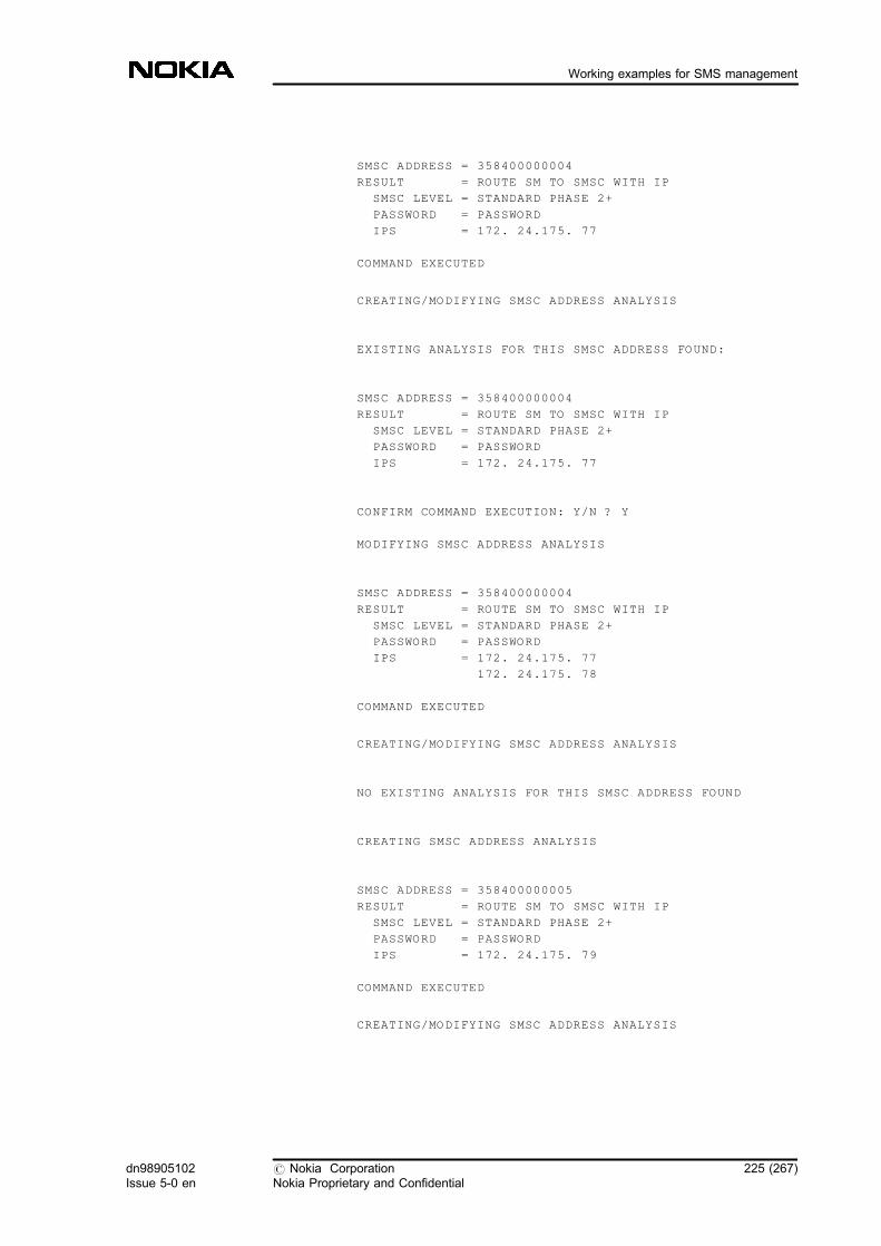
SMSC ADDRESS = 358400000004
RESULT = ROUTE SM TO SMSC WITH IP
SMSC LEVEL = STANDARD PHASE 2+
PASSWORD = PASSWORD
IPS = 172. 24.175. 77
COMMAND EXECUTED
CREATING/MODIFYING SMSC ADDRESS ANALYSIS
EXISTING ANALYSIS FOR THIS SMSC ADDRESS FOUND:
SMSC ADDRESS = 358400000004
RESULT = ROUTE SM TO SMSC WITH IP
SMSC LEVEL = STANDARD PHASE 2+
PASSWORD = PASSWORD
IPS = 172. 24.175. 77
CONFIRM COMMAND EXECUTION: Y/N ? Y
MODIFYING SMSC ADDRESS ANALYSIS
SMSC ADDRESS = 358400000004
RESULT = ROUTE SM TO SMSC WITH IP
SMSC LEVEL = STANDARD PHASE 2+
PASSWORD = PASSWORD
IPS = 172. 24.175. 77
172. 24.175. 78
COMMAND EXECUTED
CREATING/MODIFYING SMSC ADDRESS ANALYSIS
NO EXISTING ANALYSIS FOR THIS SMSC ADDRESS FOUND
CREATING SMSC ADDRESS ANALYSIS
SMSC ADDRESS = 358400000005
RESULT = ROUTE SM TO SMSC WITH IP
SMSC LEVEL = STANDARD PHASE 2+
PASSWORD = PASSWORD
IPS = 172. 24.175. 79
COMMAND EXECUTED
CREATING/MODIFYING SMSC ADDRESS ANALYSIS
dn98905102Issue 5-0 en
# Nokia CorporationNokia Proprietary and Confidential
225 (267)
Working examples for SMS management

EXISTING ANALYSIS FOR THIS SMSC ADDRESS FOUND:
SMSC ADDRESS = 358400000005
RESULT = ROUTE SM TO SMSC WITH IP
SMSC LEVEL = STANDARD PHASE 2+
PASSWORD = PASSWORD
IPS = 172. 24.175. 79
CONFIRM COMMAND EXECUTION: Y/N ? Y
MODIFYING SMSC ADDRESS ANALYSIS
SMSC ADDRESS = 358400000005
RESULT = ROUTE SM TO SMSC WITH IP
SMSC LEVEL = STANDARD PHASE 2+
PASSWORD = PASSWORD
IPS = 172. 24.175. 79
172. 24.175. 80
COMMAND EXECUTED
CREATING/MODIFYING SMSC ADDRESS ANALYSIS
NO EXISTING ANALYSIS FOR THIS SMSC ADDRESS FOUND
CREATING SMSC ADDRESS ANALYSIS
SMSC ADDRESS = 358400000006
RESULT = ROUTE SM TO SMSC WITH IP
SMSC LEVEL = STANDARD PHASE 2+
PASSWORD = PASSWORD
IPS = 172. 24.175. 81
COMMAND EXECUTED
CREATING/MODIFYING SMSC ADDRESS ANALYSIS
EXISTING ANALYSIS FOR THIS SMSC ADDRESS FOUND:
SMSC ADDRESS = 358400000006
RESULT = ROUTE SM TO SMSC WITH IP
SMSC LEVEL = STANDARD PHASE 2+
PASSWORD = PASSWORD
IPS = 172. 24.175. 81
CONFIRM COMMAND EXECUTION: Y/N ? Y
226 (267) # Nokia CorporationNokia Proprietary and Confidential
dn98905102Issue 5-0 en
SMS Guide

MODIFYING SMSC ADDRESS ANALYSIS
SMSC ADDRESS = 358400000006
RESULT = ROUTE SM TO SMSC WITH IP
SMSC LEVEL = STANDARD PHASE 2+
PASSWORD = PASSWORD
IPS = 172. 24.175. 81
172. 24.175. 82
COMMAND EXECUTED
Further information:
If you want to check the SMSC address analyses, use the CFI command.
ZCFI:TYPE=SMSC;
The example for the execution printout is the following:
SMSC ADDRESS ANALYSES
SMSC ADDRESS = 358400000004
RESULT = ROUTE SM TO SMSC WITH IP
SMSC LEVEL = STANDARD PHASE 2+
PASSWORD = PASSWORD
IPS = 172. 24.175. 77
172. 24.175. 78
SMSC ADDRESS = 358400000005
RESULT = ROUTE SM TO SMSC WITH IP
SMSC LEVEL = STANDARD PHASE 2+
PASSWORD = PASSWORD
IPS = 172. 24.175. 79
172. 24.175. 80
SMSC ADDRESS = 358400000006
RESULT = ROUTE SM TO SMSC WITH IP
SMSC LEVEL = STANDARD PHASE 2+
PASSWORD = PASSWORD
IPS = 172. 24.175. 81
172. 24.175. 82
SMSC ADDRESS = 358400000000
RESULT = ROUTE SM TO SMSC WITH IP
SMSC LEVEL = STANDARD PHASE 2+
PASSWORD = PASSWORD
IPS = 172. 24.175. 77
172. 24.175. 78
172. 24.175. 79
172. 24.175. 80
172. 24.175. 81
172. 24.175. 82
COMMAND EXECUTED
13. Patch UTPFIL in both G/IWMSCs
dn98905102Issue 5-0 en
# Nokia CorporationNokia Proprietary and Confidential
227 (267)
Working examples for SMS management
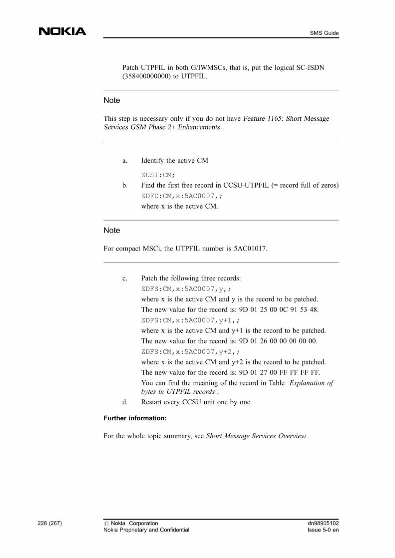
Patch UTPFIL in both G/IWMSCs, that is, put the logical SC-ISDN(358400000000) to UTPFIL.
Note
This step is necessary only if you do not have Feature 1165: Short MessageServices GSM Phase 2+ Enhancements .
a. Identify the active CM
ZUSI:CM;
b. Find the first free record in CCSU-UTPFIL (= record full of zeros)
ZDFD:CM,x:5AC0007,;
where x is the active CM.
Note
For compact MSCi, the UTPFIL number is 5AC01017.
c. Patch the following three records:
ZDFS:CM,x:5AC0007,y,;
where x is the active CM and y is the record to be patched.
The new value for the record is: 9D 01 25 00 0C 91 53 48.
ZDFS:CM,x:5AC0007,y+1,;
where x is the active CM and y+1 is the record to be patched.
The new value for the record is: 9D 01 26 00 00 00 00 00.
ZDFS:CM,x:5AC0007,y+2,;
where x is the active CM and y+2 is the record to be patched.
The new value for the record is: 9D 01 27 00 FF FF FF FF.
You can find the meaning of the record in Table Explanation ofbytes in UTPFIL records .
d. Restart every CCSU unit one by one
Further information:
For the whole topic summary, see Short Message Services Overview.
228 (267) # Nokia CorporationNokia Proprietary and Confidential
dn98905102Issue 5-0 en
SMS Guide
7 Short Message Service Troubleshooting
The following sections give instructions on what to do in case of problems relatedto SMS sending, for example, how to correct situations when subscribers do notreceive their SMs or receive them twice, or when the SM is not sent though theSMSC acknowledges the successful sending, or when SMS charging is notappropriate.
For the whole topic summary, see Short Message Services Overview.
7.1 Problems related to SMS network elements
The current SMS contains certain deficiencies in the service level because ofsome incomplete standardisation (3GPP TS 23.040 and 29.002). Thesedeficiencies can cause delay in the SM transfer to subscribers, and in the worstcase the subscribers can be jammed out so that they are unable to receive SMsunless some corrective action is taken. The defects that can occur because ofincomplete standardisation are listed below, together with possible correctivemethods.
Discrepancy between MWF and MWD
Situation:
In some circumstances an error situation can occur where the MNRF is set inVLR but the MWD is not set in HLR, or vice versa. The first one is not aproblem, because it causes only an additional indication of a mobile becomingreachable.
The latter, however, can cause the subscriber not to receive SMs. In this case asubscriber is detached and switches his/her mobile on (IMSI attach) but receivesno SMs. This is due to a signalling collision in the A interface and in the lowerlayers. If TMSI reallocation, ciphering and other activities are defined to takeplace during IMSI attach or location updating, the signalling takes so much timethat the SM arrives too early, when the mobile cannot yet answer to pagingrequests. This causes the MWD to be set again, and the delivery of the SM fails.
dn98905102Issue 5-0 en
# Nokia CorporationNokia Proprietary and Confidential
229 (267)
Short Message Service Troubleshooting
Only after a call or period location updating the VLR notices its MNRF and thedelivery is attempted again. Only priority SMs can be sent to the subscriber if theSMSC supports priority SMs. The MWD can only be cleared after a locationupdate in the HLR, or manually by the operator.
Analysis:
During update location to a new VLR, signalling delays can cause the old VLR toset its MNRF and to send an MWD to the HLR when the new VLR has noMNRF, and no knowledge of the MWD in the HLR. The reason is that the newVLR address is accepted in the HLR only after a certain period of time.
Corrective action:
Add delay to the sending of Alert-SC from HLR to SMSC so that the new VLR isready to receive the SM. The delay prevents SMs from arriving too early to theMSC. Give the following MML command:
ZMJM:ALERT=5;
It should now take about 5 seconds before subscriber B receives an SM afterswitching his/her MS on.
7.2 Problems related to SMS A interface
Subscriber does not receive SM after becoming reachable
Situation:
If a subscriber is temporarily away from the coverage area, and an SM is sent tohim/her, the MWF is set in the VLR even if the subscriber does not have MT-SMS basic service provisioned.
For more information, see Special conditions of unsuccessful MT-SM delivery.
Analysis
You can check the status of the MWF and the provisioned SMS basic services forthe subscriber with MML commands. The SMSC address is set in the subscriber'sMWD list. When the MS is reachable again, the VLR does not receive theinformation; thus it cannot clear the MWF. The VLR notices the MWF only aftera call or a period location updating.
230 (267) # Nokia CorporationNokia Proprietary and Confidential
dn98905102Issue 5-0 en
SMS Guide
The VLR knows when the subscriber is registered in the VLR (IMSI attached)and does not respond to paging requests. In this situation the subscriber ispresumed not to be under the coverage area. Usually when paging fails, an 'absentsubscriber' error indication is returned to the SMSC, which assumes that the HLRnotifies SMSC when a subscriber is reachable again (MWF and MWD are set).
Corrective action:
One method of improving reachability is to change the 'absent subscriber' errorindication towards the SMSC to another one which better indicates that thesituation is temporary. This is done by using internal error codes in the MAP andX.25 protocols that both the MSCs and SMSC support. In this case both theMWF and the MWD are set.
Another way, that depends on the SMSC functionality, is to change the 'absentsubscriber' error indication to a 'system failure' towards the SMSC. This errorcause indicates a temporary error situation in which the SMSC must poll thesubscriber periodically because only the MWF is set in the VLR. The first modelis implemented because the latter error code has other meanings as well.
If the SMSC receives 'invalid SME address' when delivering an MT-SM, itindicates that the subscriber can be in a blind spot and does not answer to paging.The SMSC polls the MS periodically with a priority SM to check if the subscriberhas come to coverage area.
For related information, see Alarms and their meanings in Short MessageService.
Subscriber receives duplicated SMs
Corrective action:
CP DATA retransmission can be controlled in the PRFILE with the following Ainterface parameters. Normally you do not need to modify these parameters:
PRFILE class 31 SHORT MESSAGE SERVICE
. 000 TC1 MINIMUM
- default value 0 seconds
- allowed range from 0 (0 s) to 3000 (30 s)
- minimum duration of the timer TC1 controlling CP-DATAresending
dn98905102Issue 5-0 en
# Nokia CorporationNokia Proprietary and Confidential
231 (267)
Short Message Service Troubleshooting
. 001 TC1 DELTA
- value presented in 10 ms
- default value 0
- no allowed range defined for this parameter
- delta to the timer TC1* value retrieved from the channel type andthe short message length
. 002 CP_DATA_REPETITION
- default value 1
- allowed range from 1 to 3
- maximum number of CP-DATA message resendings
See also Sections SMS-related general PRFILE/FIFILE parameters and Alarmsand their meanings in Short Message Service .
7.3 SMS problems related to SMRSE interface
Some frequent problem situations caused by SMRSE interface configurationfailures are presented below.
If any MO- and MT-SMS traffic breakdown happens, or connectionestablishment fails in the SMSC, as a help to identify the problem, an advancedmonitoring and checking possibility is provided with the CFI command, whichallows you to obtain information on the current state of the SMRSE links.
ZCFI:type=conn_tbl;
MS-A gets 'Message not sent this time' although MS-B receives the SMsuccessfully
Situation:
Every time an MO-SM is sent to the SMSC, a timer is started in the MSC. Thattimer controls the MO-SM transaction. If there is congestion somewhere in theSMRSE interface or the SMSC is temporarily overloaded, the MO-ACK messagecan arrive later than the default 10 s time limit. In this case the MO-ACK arrivesafter the timer expiration, therefore the SMRSE application has already sent MO-NACK towards MS-A, despite the fact that the SMSC has delivered the SMsuccessfully to MS-B.
Analysis:
232 (267) # Nokia CorporationNokia Proprietary and Confidential
dn98905102Issue 5-0 en
SMS Guide
Check the BDCU computer log of the SMS-IWMSC with the GSC serviceterminal command. The following error logs indicate this error situation:
. MO timeout
. delayed MO/ALERT-ACK
. number of delayed MO/ALERT-ACKs
The following error logs also indicate that there is some delay in the MO-SMprocessing:
. delayed MO/ALERT-NACK
. number of delayed MO/ALERT-NACKs
However, these two errors indicate a different situation from the previous one: theMO-SM transaction was unsuccessful and MS-B did not receive the SM.
Corrective action:
Increase the value of the timer controlling the MO-SM by setting the PRFILEparameter called SMRSE_MO_TIMER (31:38) to the appropriate value. Thisvalue should be the default value (10 s = 1000D) plus the maximum delay time (ifthe maximum delay time is much greater than the average delay time, then theparameter should be set to the default time plus the average delay time value).The delay time of an MO-(N)ACK is the time which elapses starting form theMO timeout until the delayed MO-(N)ACK arrives and the 'Delayed MO/ALERT-(N)ACK' error log is written. This interval can be calculated bycomparing the timestamps of that 'MO timeout' and 'Delayed MO/ALERT-(N)ACK' error log pair whose message reference in the user data information field ismatching. For example, in case of the following MO-SM transaction, which isidentified by message reference 00F5, the delay is 0.09 s.
WRITE TIME: YYYY-MM-DD HH:MM:SS
PARAMETERS: E-02 001C.00007650 00000001 000C.00009C10
USER TEXT : MO timeout.
USER DATA : 00F5
WRITE TIME: YYYY-MM-DD HH:MM:SS
PARAMETERS: E-02 001C.00007650 00000001 000C.0000DF99
USER TEXT : Delayed MO/ALERT-ACK.
USER DATA : 00F5
Note
dn98905102Issue 5-0 en
# Nokia CorporationNokia Proprietary and Confidential
233 (267)
Short Message Service Troubleshooting
1. Change the SMRSE_MO_TIMER only if the problem described aboveoccurs regularly.
2. The setting of the SMRSE_MO_TIMER requires special attention becausea timer which is not correctly configured can cause problems in the SMtransfer. For example, if you accidentally set the MO timer value too short(1.1 s instead of 11 s) it results in even more MO-NACK than beforechanging the parameter. Also, you should set this parameter to a lowervalue than the MO control timer value of the SMS application in the SMS-IWMSC, which is 12 s by default.
3. A radically increased MO timer value also means that the message entriesin the MO pending table are kept reserved for a longer time, so if there areseveral slow MO-transactions, and at the same time lots of incoming MO-SMs, the MO pending table can be filled up. Consequently, there is no freemessage entry for every MO-SM, and those without message entry arenegatively acknowledged back to the SMS application.
Configure the parameter very carefully to reach the optimal settings.
PRFILE class 31 SHORT MESSAGE SERVICE
. 038 SMRSE_MO_TIMER
- default value 1000D (10 s)
- allowed range from 0 (0 s) to 2000D (20 s)
- SMRSE MO-SM response timer in SMS-IWMSC
Subscriber receives duplicated SMs
Situation:
Every time the SMRSE application in the SMS-GMSC forwards an MT-SM tothe SMS application, a timer is started which controls that MT-SM transaction. Ifthere is a congestion in the network towards the MS, or part of the NSS isoverloaded, the MT-ACK sent by the SMS application can arrive later than thedefault 90 s time limit. In this case the MT-ACK arrives after the timer expiration,therefore the SMRSE application has already sent MT-NACK towards theSMSC. Consequently, the SMSC re-sends this SM despite the fact that MS-B hassuccessfully received it.
Analysis:
Check the BDCU computer log of the SMS-GMSC with the GSC serviceterminal command. The following error logs indicate this error situation:
234 (267) # Nokia CorporationNokia Proprietary and Confidential
dn98905102Issue 5-0 en
SMS Guide
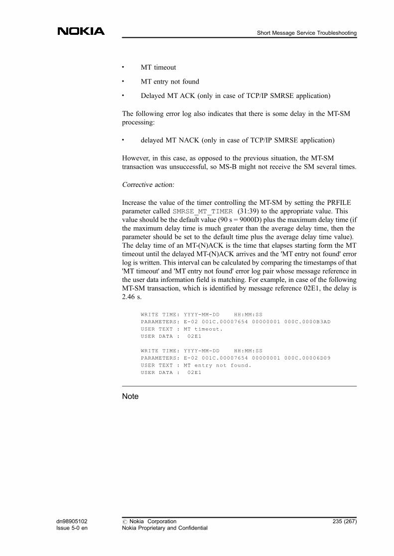
. MT timeout
. MT entry not found
. Delayed MT ACK (only in case of TCP/IP SMRSE application)
The following error log also indicates that there is some delay in the MT-SMprocessing:
. delayed MT NACK (only in case of TCP/IP SMRSE application)
However, in this case, as opposed to the previous situation, the MT-SMtransaction was unsuccessful, so MS-B might not receive the SM several times.
Corrective action:
Increase the value of the timer controlling the MT-SM by setting the PRFILEparameter called SMRSE_MT_TIMER (31:39) to the appropriate value. Thisvalue should be the default value (90 s = 9000D) plus the maximum delay time (ifthe maximum delay time is much greater than the average delay time, then theparameter should be set to the default time plus the average delay time value).The delay time of an MT-(N)ACK is the time that elapses starting form the MTtimeout until the delayed MT-(N)ACK arrives and the 'MT entry not found' errorlog is written. This interval can be calculated by comparing the timestamps of that'MT timeout' and 'MT entry not found' error log pair whose message reference inthe user data information field is matching. For example, in case of the followingMT-SM transaction, which is identified by message reference 02E1, the delay is2.46 s.
WRITE TIME: YYYY-MM-DD HH:MM:SS
PARAMETERS: E-02 001C.00007654 00000001 000C.0000B3AD
USER TEXT : MT timeout.
USER DATA : 02E1
WRITE TIME: YYYY-MM-DD HH:MM:SS
PARAMETERS: E-02 001C.00007654 00000001 000C.00006D09
USER TEXT : MT entry not found.
USER DATA : 02E1
Note
dn98905102Issue 5-0 en
# Nokia CorporationNokia Proprietary and Confidential
235 (267)
Short Message Service Troubleshooting

1. Change the SMRSE_MT_TIMER only if the problem described aboveoccurs regularly.
2. The setting of the SMRSE_MT_TIMER requires special attention, becausea timer which is not correctly configured can cause problems in the SMtransfer. For example, if you accidentally set the MT timer value too shortit causes more MT-NACK. Furthermore, a too long MT timer can affectthe retransmission of the unsuccessful MT-SMs in the SMSC. That is, withlonger MT timer the SMSC has to store the pending messages for a longertime, so its buffers can be filled more easily, and this can result incongestion. On the other hand, the value of this parameter can not exceedthe MT control timer of the SMSC either.
3. A radically increased MT timer value also means that the message entriesin the MT pending table are kept reserved for a longer time, so if there areseveral slow MT-transactions and at the same time lots of incoming MT-SMs, the MT pending table can be filled up. Consequently, there is no freemessage entry available for every MT-SM and these SMs are negativelyacknowledged back to the SMSC.
Configure the parameter very carefully to reach the optimal settings.
PRFILE class 31 SHORT MESSAGE SERVICE
. 039 SMRSE_MT_TIMER
- default value 9000D (90 s)
- allowed range from 0 (0 s) to 15000D (150 s)
- SMRSE MT-SM response timer in SMS-GMSC
7.4 Problems related to SMS charging
Real charging information is not forwarded to the charging application
Situation:
It can happen that the subscriber, for example, removes the battery from the MS(or in some mobiles, pushes the 'red button') right after sending a short messageand thus, commits fraud.
For more information, see MO-SM fraud prevention .
Analysis:
236 (267) # Nokia CorporationNokia Proprietary and Confidential
dn98905102Issue 5-0 en
SMS Guide

For example, if the subscriber removes the battery (or pushes the 'red button')right after sending a short message, the subscriber forces the SMS application toinform the charging application about the MO-SM being unsuccessful despite thefact that the MO-SM was delivered to the SMSC successfully.
Corrective action:
You can use the 031:0025 CHAR_WITHOUT_ACK_TO_MS PRFILEparameter to prevent MO-SM fraud. For related information, see Short messagerouting , and Short message charging .
dn98905102Issue 5-0 en
# Nokia CorporationNokia Proprietary and Confidential
237 (267)
Short Message Service Troubleshooting

238 (267) # Nokia CorporationNokia Proprietary and Confidential
dn98905102Issue 5-0 en
SMS Guide
8 Additional information on SMS
8.1 MT operation in VMSC
SMS resending
In handover cases the MSC notices that a handover occurred and sets a new timersupervision that is greater than the one in the MS. The SMS resending isperformed only after the supervision time has exceeded, because it is possible thatthe MS has not received the first CP-DATA message at all.
The following logical timers are presented in the message sequences listed below:
T1 Supervision for CP-ACK message when CP-DATA messageis sent. It is calculated from the SMS length, and variesbetween 3 - 20 seconds.
T2 The overall supervision time for the total SM transfer.
T5 The time period after which the MS is likely to have receivedthe CP-DATA message. It is calculated from the SM lengthand varies between 1 - 15 seconds. If a handover is receivedduring this time, timer T1 is set again in order to see whetherthe MS received the first CP-DATA message.
T6 If a handover is received during a time period after which theMS is likely to have received the CP-DATA message, thisguard timer is set before the CP-DATA message is resent.This may happen after the T5 has expired.
The following figure shows a case where a handover takes place after the MS hasreceived the CP-DATA message, and the MSC delays the SM resending. Theresult is that no duplication is made as the MS has time to acknowledge this withthe CP-ACK message:
dn98905102Issue 5-0 en
# Nokia CorporationNokia Proprietary and Confidential
239 (267)
Additional information on SMS
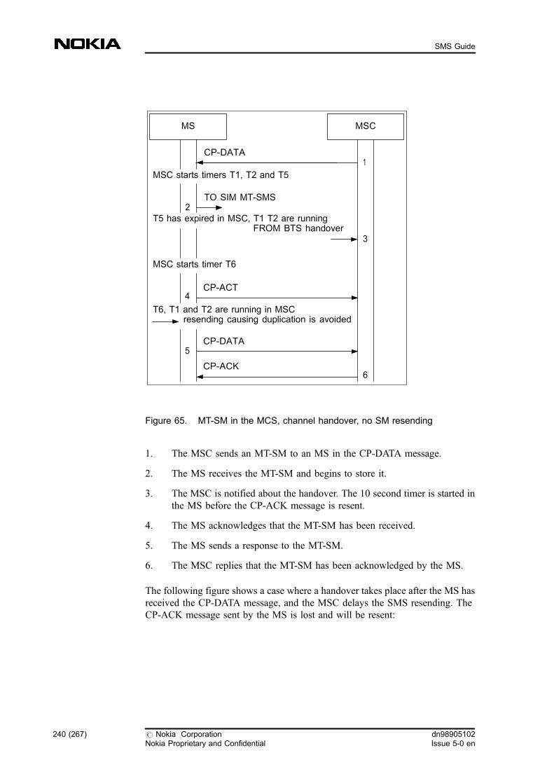
Figure 65. MT-SM in the MCS, channel handover, no SM resending
1. The MSC sends an MT-SM to an MS in the CP-DATA message.
2. The MS receives the MT-SM and begins to store it.
3. The MSC is notified about the handover. The 10 second timer is started inthe MS before the CP-ACK message is resent.
4. The MS acknowledges that the MT-SM has been received.
5. The MS sends a response to the MT-SM.
6. The MSC replies that the MT-SM has been acknowledged by the MS.
The following figure shows a case where a handover takes place after the MS hasreceived the CP-DATA message, and the MSC delays the SMS resending. TheCP-ACK message sent by the MS is lost and will be resent:
MS
CP-DATA
4
MSC
1
6
MSC starts timers T1, T2 and T5
TO SIM MT-SMS
T5 has expired in MSC, T1 T2 are runningFROM BTS handover
MSC starts timer T6
CP-ACT
3
2
CP-DATA
CP-ACK
T6, T1 and T2 are running in MSCresending causing duplication is avoided
5
240 (267) # Nokia CorporationNokia Proprietary and Confidential
dn98905102Issue 5-0 en
SMS Guide

Figure 66. MT-SM in the MSC, channel handover, SM resending takes place
1. The MSC sends an MT-SM to an MS within the CP-DATA message.
2. The MS receives the MT-SM and begins to store it.
3. The MSC is notified about the handover.
4. Supervision timer T6 expires.
5. The SM resending takes place.
6. The MS acknowledges that the MT-SM has been received.
7. The MS sends a response to the MT-SM.
8. The MSC replies that the MT-SM has been acknowledged by the MS.
MS
CP-DATA
MSC
1
8
MSC starts timers T1, T2 and T5
TO SIM MT-SMS
T5 has expired in MSC, T1 T2 are runningFROM BTS handover
MSC starts timer T6
3
2
CP-DATA
CP-ACK6
FROM TIMER T64
CP-DATA
CP-ACK
5
7
dn98905102Issue 5-0 en
# Nokia CorporationNokia Proprietary and Confidential
241 (267)
Additional information on SMS
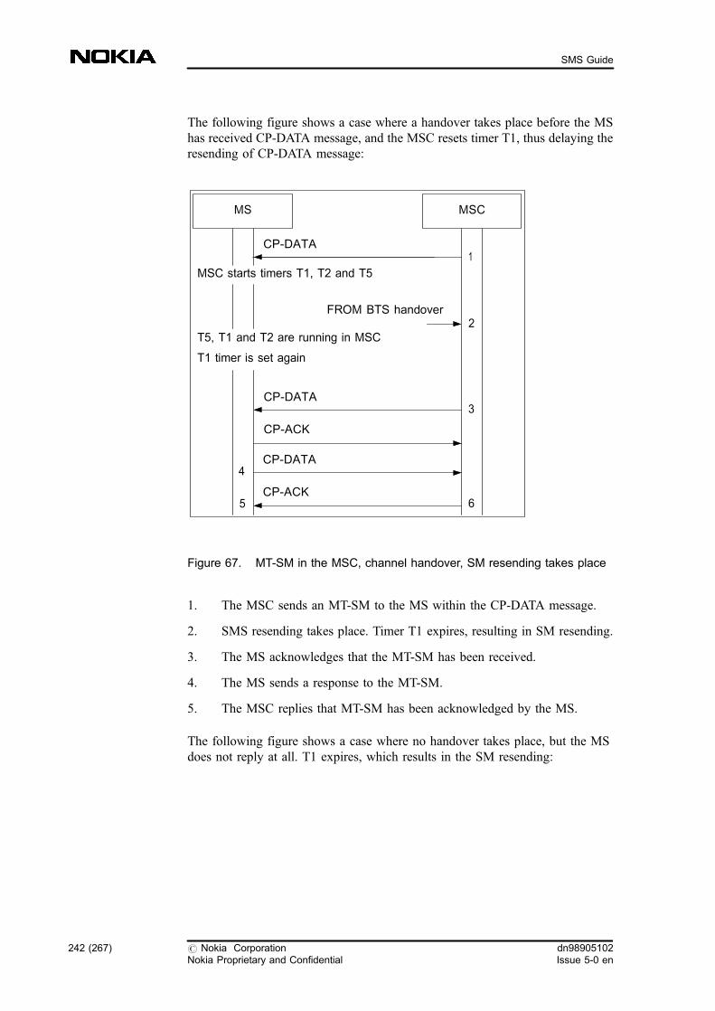
The following figure shows a case where a handover takes place before the MShas received CP-DATA message, and the MSC resets timer T1, thus delaying theresending of CP-DATA message:
Figure 67. MT-SM in the MSC, channel handover, SM resending takes place
1. The MSC sends an MT-SM to the MS within the CP-DATA message.
2. SMS resending takes place. Timer T1 expires, resulting in SM resending.
3. The MS acknowledges that the MT-SM has been received.
4. The MS sends a response to the MT-SM.
5. The MSC replies that MT-SM has been acknowledged by the MS.
The following figure shows a case where no handover takes place, but the MSdoes not reply at all. T1 expires, which results in the SM resending:
MS
CP-DATA
MSC
1
MSC starts timers T1, T2 and T5
FROM BTS handover2
CP-DATA
CP-ACK
4
T5, T1 and T2 are running in MSC
T1 timer is set again
6
CP-DATA
CP-ACK
3
5
242 (267) # Nokia CorporationNokia Proprietary and Confidential
dn98905102Issue 5-0 en
SMS Guide

Figure 68. MT-SM in the MSC, T1 expires, SM resending takes place
1. The MSC sends an MT-SM to the MS within the CP-DATA message.
2. SM resending takes place.
3. The MS acknowledges that the MT-SM has been received.
4. The MS sends a response to the MT-SM.
5. The MSC replies that the MT-SM has been acknowledged by the MS.
Values for timers
The MSC has the timeout supervision T1 for CP-ACK. The timeout is calculatedfrom the SM length according to the following rules:
. Channel type is SACCH :
(SMS_LENGTH/18)*0.96 sec + 6 sec + delta
. Channel type is SDCCH :
(SMS_LENGTH/20)*0.24 sec + 3 sec + delta
MS
CP-DATA
MSC
1
MSC starts timers T1, T2 and T5
2
CP-ACK
4CP-DATA
CP-ACK
CP-DATA
T1 has expired in MSC, T2 is running
3
5
dn98905102Issue 5-0 en
# Nokia CorporationNokia Proprietary and Confidential
243 (267)
Additional information on SMS

If CP-ACK is not received during the time calculated on the basis of the channeltype and SM length, it will be resent. Resending counts may vary from 1 to 3.Counts and timer delta values can be set in Parameter File (PRFILE), Class 31.
In practice, timer T1 varies from 3.3 to 15 seconds, and SMS_LENGTH in the Ainterface from 33 to 172 octets.
Timer T5 is related to T1, it is the part of T1 used for sending CP-DATA to theMS when T1 includes also the CP-ACK sent by the mobile station. Therefore T5is estimated to be T1 - 5 seconds in SACCH channel, and T1 - 2 in SDCCHchannel.
Timer T6 is derived from the MS resending timer. In the MS the timer value is 10seconds, therefore the MSC has the value of 13 seconds.
Timer T2 is the maximum time that can be left for the A interface signalling.When the SM arrives through the MAP interface to the MSC, the maximumtimeout in the SMS-GMSC for sending the MT-SM is 60 seconds. The 58 secondtimer is set for the VMSC MAP, and the 55 second time is left for the Ainterface.
You can find an estimate of the worst case for T2 below:
. If a handover takes place at the latest point when the resending is possible,the time is Start + T1 (that is, 15 s).
. The next step is to start resending the guard timer T6. T6 is 13 seconds (inMS 10 seconds, in MSC a margin of 3 seconds must be added).
. T6 expires, and resending takes place. T1 is started again, the time now isStart + T1 + T6 (that is, 15 + 13 s).
. The MS gives an acknowledgement just before T1 expires, the time now isStart + T1 + T6 + T1 (that is, 15 + 13 + 15 s).
If you want to make sure that a duplication exists, prepare to wait for responsesfor a long time. Here the total time would be 43 seconds, and that does notinclude MS paging, authentication, and what needs to be done before beginningto send an MT-SM.
Also check when resending is possible, that is, how much time has already beenconsumed by comparing the present time with the time left in T2. For example, ifseveral handovers take place, each of which causes T6 to be reset, there are 14seconds left in T2 at the point when the last handover takes place, and T1 iscalculated to be 15 seconds, stop the SM transfer. The reason for the interruptionis that the time left would probably not be sufficient.
For more information, see VMSC and VLR .
244 (267) # Nokia CorporationNokia Proprietary and Confidential
dn98905102Issue 5-0 en
SMS Guide
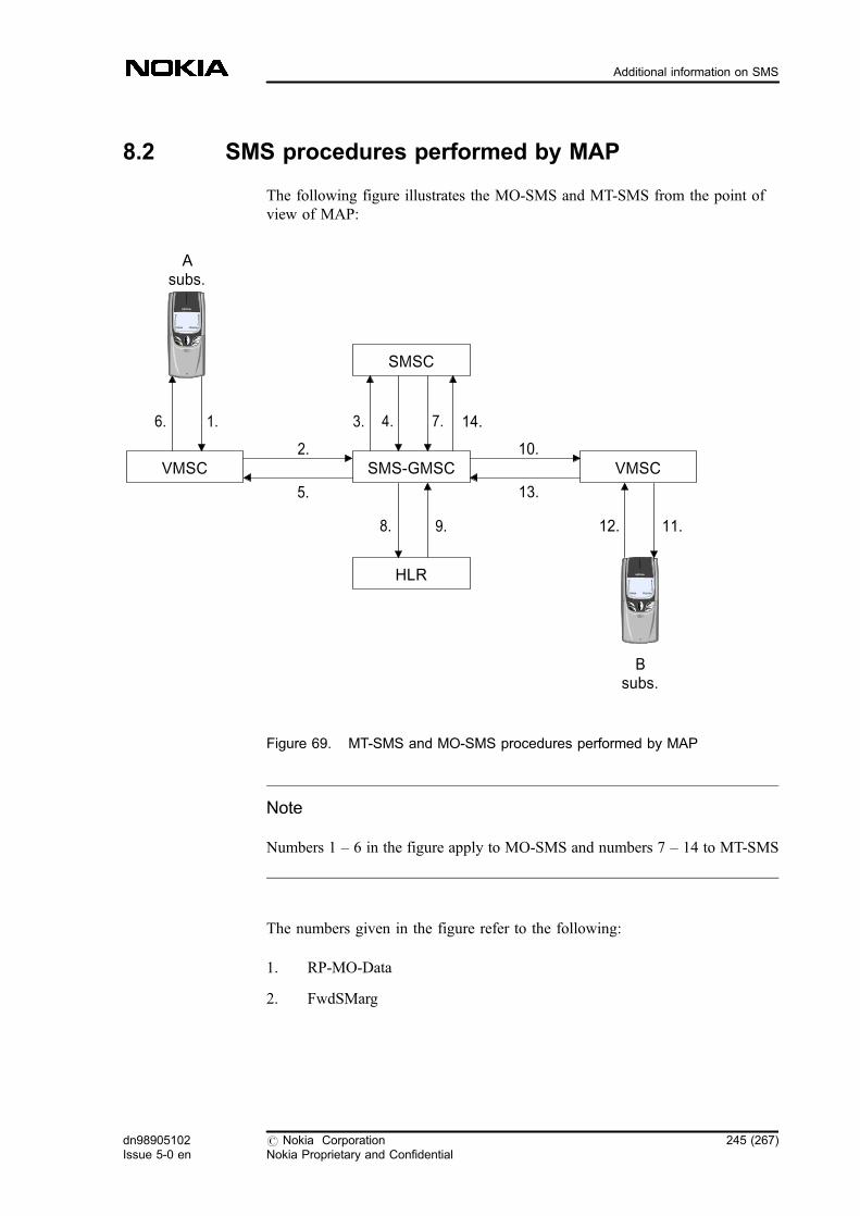
8.2 SMS procedures performed by MAP
The following figure illustrates the MO-SMS and MT-SMS from the point ofview of MAP:
Figure 69. MT-SMS and MO-SMS procedures performed by MAP
Note
Numbers 1 � 6 in the figure apply to MO-SMS and numbers 7 � 14 to MT-SMS
The numbers given in the figure refer to the following:
1. RP-MO-Data
2. FwdSMarg
Asubs.
1.6.
2.
5.
8. 9.
3. 4. 7.
10.
13.
14.
SMS-GMSCVMSC VMSC
SMSC
HLR
12. 11.
Bsubs.
dn98905102Issue 5-0 en
# Nokia CorporationNokia Proprietary and Confidential
245 (267)
Additional information on SMS

3. SC_RP_MO_DATA
4. SC_RP_MO_ACK
5. FwdSMres
6. RP-MO-Ack
7. SC_RP_MT_DATA
8. SRIforSMarg
9. SRIforSMres
10. FwdSMarg
11. RP-MT-Data
12. RP-MT-Ack
13. FwdSMres
14. SC_RP_MT_ACK
The following paragraphs explain the procedures in detail:
1. MobileOrginatingSM
The MO SMS procedures are used to forward an SM from a mobilesubscriber to an SMSC . The MAP offers a procedure which can be used totransfer an MO-SM from the VMSC to the SMS-IWMSC .
a. MO SMS transfer procedure in MAP version 1 and version 2:
ForwardSM (FSM) begins a dialogue, and the VMSC sends theoperation in the TC-BEGIN message when it receives an SM fromthe MS. If the SMS-IWMSC knows the SMSC, it transfers the SMto it.
When the SMS-IWMSC receives a response for the SM from theSMSC, it transfers the response to the VMSC.
2. RoutingInfoEnquiryForSM
The SM handling function of the SMS-GMSC requests the routinginformation from the HLR when it receives an MT-SM from the SMSC.
When the routing information is received, and the subscriber is registeredin the MSC area in question (SMS-GMSC), the SMS-GMSC itself sendsthe MS to the MS. Otherwise the SMS-GMSC transfers the SM to theVMSC.
246 (267) # Nokia CorporationNokia Proprietary and Confidential
dn98905102Issue 5-0 en
SMS Guide
RoutingInfoEnquiryForSM procedures offered by MAP are different inInformServiceCentre operation to tell the SMSC which ISDN number isused to indicate the availability of the SM for SMs.
a. RoutingInfoEnquiryForSM procedure in MAP version 1:
SendRoutingInfoForSM (SRI-SM) begins a dialogue, and the SMS-GMSC sends the operation in the TC-BEGIN message when itreceives an SM from the SMSC.
After handling the procedure, the HLR sends the result or an errormessage for SRI-SM in TC-END.
b. RoutingInfoEnquiryForSM procedure in MAP version 2:
. The SendRoutingInfoForSM (SRI-SM) begins a dialogue,and the SMS-GMSC sends the operation in the TC-BEGINmessage when it receives an SM from the SMSC.
. After handling the procedure, the HLR sends the result or anerror message for the SRI-SM in the TC-END message.
. The HLR can send an optional InformServiceCentreoperation which is packed in the same network primitive asthe SRI-SM result/error.
3. MobileTerminatingSM
The MT-SM transfer procedure is used to forward an SM or several SMsfrom an SMSC to a mobile subscriber. The MAP offers a procedure whichcan be used to transfer an MT-SM from the SMS-GMSC to the VMSC.
MT-SM transfer procedures offered by MAP are different in the MAPversions 1 and 2. In version 1, only one SM can be transferred during adialogue, but in version 2, several SMs can be transferred during the samedialogue.
a. MT-SM transfer procedure in MAP version 1:
. ForwardSM begins a dialogue, and the SMS-GMSC sends theoperation in the TC-BEGIN message if it has received routinginformation from the HLR, indicating that the subscriber isregistered in another MSC area. If the subscriber is reachable,the VMSC sends him/her the SM.
. When the VMSC receives a response for the SM from theMS, it transfers the response to the SMS-GMSC. Afterreceiving the response, the SMS-GMSC may start ReportSM-DeliveryStatus, in any case, it transfers the responses to theSMSC.
b. MT-SM transfer procedure in MAP version 2:
dn98905102Issue 5-0 en
# Nokia CorporationNokia Proprietary and Confidential
247 (267)
Additional information on SMS

The ForwardSM operation can appear several times in a dialogue.Furthermore, the first FSM may contain only the MAP-OPEN PDUif the PDU and the SM are too large to fit together in one TCAPprimitive.
. The ForwardSM begins a dialogue, and the SMS-GMSCsends the operation in the TC-BEGIN message if it hasreceived routing information from the HLR indicating that thesubscriber is registered in another MSC. If the message is toolong to fit in the network message frame, only the MAP-OPEN-PDU is sent in the TC-BEGIN message, and themessage part is sent separately after that. If the MS can bereached, the VMSC sends an SM to it.
. When the VMSC receives a response for the SM from theMS, it transfers the response to the SMS-GMSC. Afterreceiving the response, the SMS-GMSC can start theReportSM-DeliveryStatus, in any case, it transfers theresponses to the SMSC.
. In the multiple SM transfer, the FSM service can be usedseveral times.
. The FSM is always acknowledged to the SMSC before thenext SM is sent.
4. ReportSM-DeliveryStatus
Note
This operation was called SetMessageWaitingData in the old specification.
If the MT-SM transfer fails, the SMS-GMSC can inform this to the HLRby using the ReportSM-DeliveryStatus operation. The following figureillustrates a situation where MT-SM sending fails and the HLR is notified:
248 (267) # Nokia CorporationNokia Proprietary and Confidential
dn98905102Issue 5-0 en
SMS Guide

Figure 70. MT-SM sending fails, HLR is notified
The numbers given in the figure refer to the following:
a. SRIforSMarg/res
b. FwdSMarg/res
c. ReportSM-Delivery Status arg
d. ReportSM-Delivery Status res
The SMS-GMSC informs the HLR if an absent subscriber, unidentifiedsubscriber, or SM delivery failure with 'error cause MS memory capacityexceeded' indication is received from the visited MSC, and thecorresponding flags received in the InformServiceCentre operation are notalready set, or the SMSC address is not yet included in the MWD set. TheSMS-GMSC may also invoke the procedure when the transfer wassuccessful, if the MNRF and MCEF flags, or both, were set in the HLR.
a. ReportSM-DeliveryStatus procedure in MAP version 1 and version2:
. ReportSM-DeliveryStatus (RSM-DS) begins a dialogue, andthe SMS-GMSC sends the operation in the TC-BEGINmessage when it receives ForwardSM response from theVMSC.
. After handling the procedure, the HLR sends the result or anerror message for RSM-DS in the TC-END message.
2.
1. 3. 4.
VMSC SMS-GMSC
SMSC
HLR
dn98905102Issue 5-0 en
# Nokia CorporationNokia Proprietary and Confidential
249 (267)
Additional information on SMS
5. ReadyForSM
When receiving the ProcessAccessRequest or UpdateLocationAreaindication from the MS, while the MS not reachable flag (MNRF) is set,the VLR starts the ReadyForSM procedure to the HLR.
The ReadyForSM procedures offered by MAP are different in MAPversions 1 and 2.
a. ReadyForSM in MAP version 1
The NoteSubscriberPresent operation begins and ends a dialogue,and the VLR sends the operation in the TC-BEGIN message to theHLR. Because this is a class 4 operation, and the procedure does notcontain any other operations, the dialogue is ended immediately.
b. ReadyForSM in MAP version 2
The ReadyForSM operation begins a dialogue, and the VLR sendsthe operation in the TC-BEGIN message to the HLR.
If an error occurs in the HLR, the HLR sends an error messagecontaining UnknownSubscriber, DataMissing, FacilityNotSupportedand SystemFailure, otherwise it sends an empty result for theReadyForSM in the TC-END message to the VLR.
6. Alert-SC
When the subscriber has an SMSC address or addresses in the MWD, andthe HLR receives ReadyForSM, UpdateLocation or SupplementaryService Control request for this subscriber, it can start Alert-SC procedureto all SMSCs included in the subscriber's MWD.
The Alert-SC procedures offered by MAP are different in MAP version 1and 2.
a. Alert-SC in MAP version 1
The Alert-SC-WithoutResult operation begins and ends a dialogue,and the HLR sends the operation in the TC-BEGIN message.Because this is a class 4 operation, and the procedure does notcontain any other operations, the dialogue is ended immediately.
b. Alert-SC in MAP version 2
The Alert-SC operation begins the dialogue, and the HLR sends theoperation in the TC-BEGIN message to the SMS-IWMSC.
If an error occurs in the HLR, the HLR sends an error messagecontaining the UnknownSubscriber, DataMissing,FacilityNotSupported and SystemFailure, otherwise it sends anempty result for Alert-SC in the TC-END message.
The following figure illustrates the ReadyForSM and Alert-SC procedures:
250 (267) # Nokia CorporationNokia Proprietary and Confidential
dn98905102Issue 5-0 en
SMS Guide
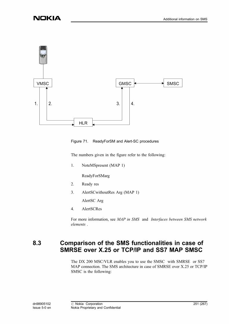
Figure 71. ReadyForSM and Alert-SC procedures
The numbers given in the figure refer to the following:
1. NoteMSpresent (MAP 1)
ReadyForSMarg
2. Ready res
3. AlertSCwithoutRes Arg (MAP 1)
AlertSC Arg
4. AlertSCRes
For more information, see MAP in SMS and Interfaces between SMS networkelements .
8.3 Comparison of the SMS functionalities in case ofSMRSE over X.25 or TCP/IP and SS7 MAP SMSC
The DX 200 MSC/VLR enables you to use the SMSC with SMRSE or SS7MAP connection. The SMS architecture in case of SMRSE over X.25 or TCP/IPSMSC is the following:
VMSC
1. 2. 3. 4.
GMSC SMSC
HLR
dn98905102Issue 5-0 en
# Nokia CorporationNokia Proprietary and Confidential
251 (267)
Additional information on SMS

Figure 72. SMS architecture in case of SMRSE over X.25 or TCP/IP
The SMS architecture in case of SS7 MAP is the following:
MS
VMSC
SMSC
HLR
A
MAP-C
Gb
SGSN
SMS-IWMSC
SMS-GMSC
SMRSE
MAP-CSMRSE
MAP-E
MAP-E
MAP-Gd
MAP-Gd
252 (267) # Nokia CorporationNokia Proprietary and Confidential
dn98905102Issue 5-0 en
SMS Guide

Figure 73. SMS architecture in case of SS7 MAP
Due to the different architecture, the provided functionalities are different in thecases given above.
Note that this section does not cover the functionalities provided with the SMRSEover TCP/IP SMSC.
8.3.1 Functional differences between SMRSE over X.25 or TCP/IP and SS7MAP SMSC
Charging and statistics
The charging and statistic functionalities in the SMS-IWMSC and the SMS-GMSC are the following:
. Creating CDR s
Subscriber billing can be based on the CDRs generated in the SMS-IWMSC and the SMS-GSMC. See the following examples:
MSVMSC
SMSC
HLR
A MAP-E
MAP-C
SGSN
MAP-Gd
dn98905102Issue 5-0 en
# Nokia CorporationNokia Proprietary and Confidential
253 (267)
Additional information on SMS
1. Those home subscribers' SMs who are roaming out of the HPLMNcan be charged in the SMS-IWMSC.
2. The SMs generated by applications can be charged in the SMS-GMSC where the tariff class information is available, or when thedestination home subscriber is out of the HPLMN, the applicationgenerated SMs can be charged only in the SMS-GMSC.
3. The charging of the command SM and/or the status report SM canbe in the SMS-GMSC and the SMS-IWMSC when the homesubscriber is out of the HPLMN.
The CDRs generated in the SMS-IWMSC and the SMS-GMSC are notavailable in case of SS7 MAP SMSC, however, if the charging is in theSS7 MAP SMSC and the SMSC has an interface with the Billing Centre,the above cases can be handled also in the SS7 MAP SMSC.
. Field reporting - service measurement
T21 SHORT MESSAGE MT GMSC and T22 SHORT MESSAGE MOIWMSC counters are not updated in case of MAP SMSC.
. MAP measurement
The SendRoutingInfoForSM and the ReportSM-DeliveryStatus operationare not counted according to the source in the MSC in case of MAPSMSC.
. Online call monitoring (OLCM) and Lawfully Authorized ElectronicSurveillance (LAES) information is not available from the SMS-IWMSCand the SMS-GMSC in case of MAP SMSC.
For more information, see Short message charging , and SMS-related statistics .
Routing of SMs to service applications
The SMS routing analyses are used to route the SMs based on PID and/or prefixtowards the proper SMSC. The logic of these analyses is strongly determined bythe used SMS architecture, therefore in case of changing the SMS architecture theSMS routing analysis and the SMSC address analysis should be reconsidered inall MSCs.
Tips for checking the analyses:
. The result of SMSC address analysis can be number modification orSMSC deny in case of SS7 SMSC. Beyond these results, the result can beAEN(s) in case of X.25 over SMRSE SMSC.
. If you uses tariff class information for charging SMs, it is preferable toinclude this information in SMS routing analysis results in every MSC ofthe HPLMN.
254 (267) # Nokia CorporationNokia Proprietary and Confidential
dn98905102Issue 5-0 en
SMS Guide
Additionally, the SCCP routings are also different:
. In MSC: using GT analysis, the result of the GT analysis should be therouting to the MAP SMSC in case of MAP SMSC, and routing to theSMS-IWMSC in case of SMRSE SMSC.
. In HLR: using GT analysis, the result of the GT analysis should be therouting to the MAP SMSC in case of MAP SMSC, and routing to theSMS-GMSC in case of SMRSE SMSC.
For further information, see Short message routing .
MAP interface
The MAP operation SendIMSI is not available in case of MAP SMSC, thereforethe IMSI as a subscriber identifier cannot be used in charging. However, the SS7MAP SMSC implements the SendIMSI operation and fetches the subscriber'sIMSI from the HLR. The MAP-Gd interface is also supported by the SS7 MAPSMSC, so the subscribers using only GPRS can send and receive short messagesto and from the MAP SS7 SMSC.
PRFILE parameters without effects in case of MAP interface
. CHARGING BASED ON IMSI (feature 619): the value of this parameterhas no effect
. SMS_EXT_MSG_REF_IN_X25 (feature 619): the value of this parameterhas no effect
. MMS_SMSC_TIMER (feature 620): the value of this parameter has noeffect
For related information, see SMS-related general parameter file (PRFILE/FIFILE) parameters .
Possible defects
The function which provides corrective method for the incompletestandardisation problems (subscriber does not receive SM after becomingreachable, discrepancy between Messages Waiting (MWF) and MWD ) does notwork in case of SS7 SMSC. For further information about the function see thefeature description of Feature 714: Short Message Service Enhancements .
dn98905102Issue 5-0 en
# Nokia CorporationNokia Proprietary and Confidential
255 (267)
Additional information on SMS

8.4 Functions of SMSC level in SMS
The available functions of SMS, and the SMSC levels associated with them aredescribed in the interface specification of MSC-SMSC Interface for TCP/IP in theMSC Specification .
The following addresses can be transferred only if the SMSC level is set to N3.
. MO logical SMSC address in Rp_timeout message
Making the use of predefined SMSC addresses unnecessary throughenabling that the status report is appropriate even if the operator has severalSMSC addresses.
. Alert SC address in Alert message
Identifying the SMSC to be used for the alerting procedure.
. IMSI and VMSC/SGSN address in Rp_Ack and RP_error message (MTcase)
IMSI and VMSC/SGSN address sent to the SMSC in MT SMS
The IMSI number of subscriber B and the destination VMSC/SGSN address aresent to the SMSC (on the TCP/IP interface) in the MT SMS acknowledgement(RPAck and RPError) messages. In the RPAck message the VMSC or the SGSNaddress is sent depending on which delivery was successful, while in the RPErrormessage both addresses are sent regardless of the HLR settings.
The SMSC requires the IMSI and VMSC/SGSN data for statistical purposes. Inaddition, if the SMSC charges for SMS, the VMSC address is a useful piece ofinformation for locating subscriber B.
Note
You can use this feature if you have the SMSC connected through SMRSE withTCP/IP. MAP version 3 is needed for this functionality. For details, refer to thefeature activation instructions of Feature 1165: Short Message Services, GSMPhase 2+ Enhancements . The SMSC level has to be set to N3.
The following message sequence shows how the parameters are sent in theRP_Ack message.
256 (267) # Nokia CorporationNokia Proprietary and Confidential
dn98905102Issue 5-0 en
SMS Guide
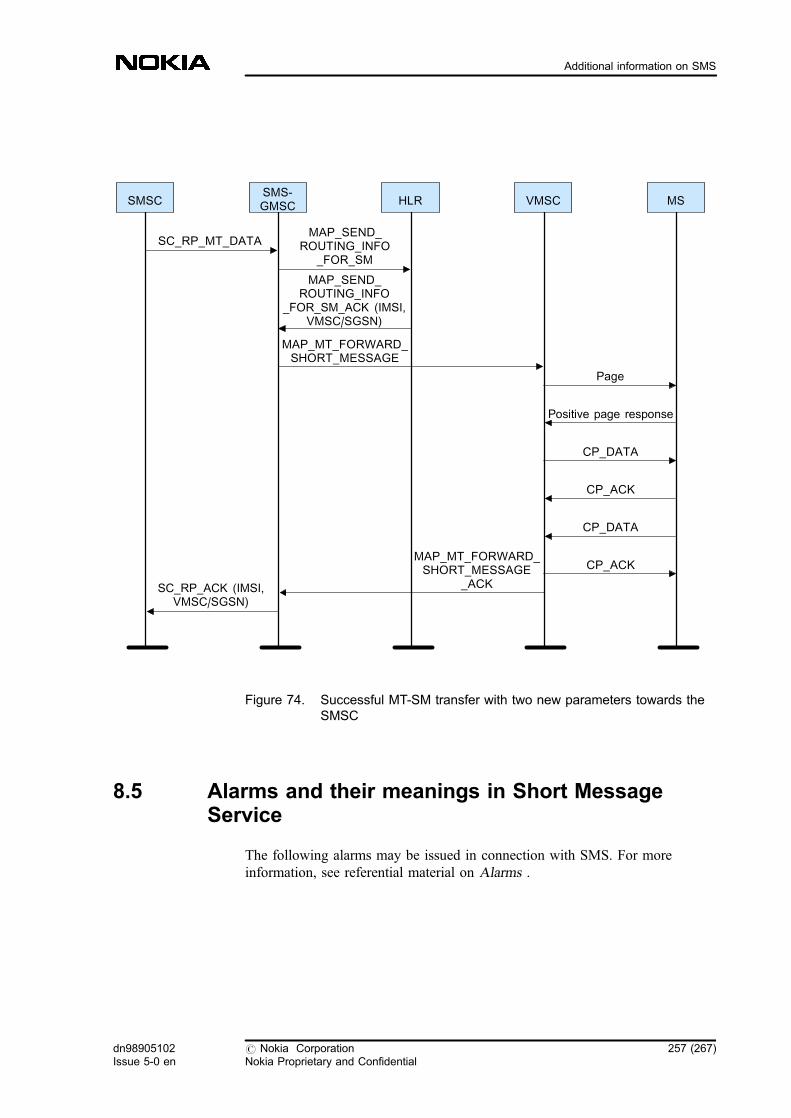
Figure 74. Successful MT-SM transfer with two new parameters towards theSMSC
8.5 Alarms and their meanings in Short MessageService
The following alarms may be issued in connection with SMS. For moreinformation, see referential material on Alarms .
SMSCSMS-GMSC HLR VMSC MS
SC_RP_MT_DATAMAP_SEND_
ROUTING_INFO_FOR_SM
MAP_SEND_ROUTING_INFO
_FOR_SM_ACK (IMSI,VMSC/SGSN)
MAP_MT_FORWARD_SHORT_MESSAGE
Page
Positive page response
CP_DATA
CP_ACK
CP_DATA
CP_ACKMAP_MT_FORWARD_SHORT_MESSAGE
_ACKSC_RP_ACK (IMSI,VMSC/SGSN)
dn98905102Issue 5-0 en
# Nokia CorporationNokia Proprietary and Confidential
257 (267)
Additional information on SMS
. 1024, HAND CREATION FAIL
This alarm is issued if there is overload in the network or in one of theunits, or in situations when the capacity is increased (especially in thetransit MSC) because of heavy traffic.
. 1088, SMSC ACCESS FAILURE
This alarm is used to indicate an unauthorised attempt to create aconnection. It is raised if there is a failed attempt for a connection. Thesituation occurs if the SC address analysis is missing for the SMSC whichtries to open a connection.
The alarm is also used when the connection drops down in anunexceptional way, for example, when the physical medium breaks down.
. 2439, SMSC LINK FAILURE
The system sets the alarm when SM sending to SMSC fails because of linkfailure. The priority of the alarm is three stars. Check the link state andconnection parameters as well as hardware. The system clears the alarmautomatically after recovery. This alarm is related to X.25 and TCP/IP link.
In case of TCP/IP links, the alarm is generated only for physical SMSCaddresses. Logical SMSC addresses cannot be alarmed.
. 1572, SMS SUBMIT PRIMITIVE ENCODING FAILURE
Due to the use of the PNP service in the SMS, an error occurred in theencoding of the TPDU . The data in the TPDU contains erroneous values.This alarm is related to the A interface.
. 1647, OPERATION TIMER EXPIRY
An operation has been sent to the network, but an acknowledgement to ithas not been received fast enough, and as a result, the ongoing dialogue isinterrupted. The effect on the functioning of the system and on the servicereceived by the subscriber depends on the operation in question. Thedisturbance can indicate a routing problem, or congestion in the networkelement to which the operation was sent. This alarm is related to MAPprotocol.
. 1652, DECODING ERROR OF THE MESSAGE RECEIVED FROMTHE MS
The alarm notifies the user about a message which was received from theMS and could not be decoded. This alarm is generated when CPDUencoding fails due to:
258 (267) # Nokia CorporationNokia Proprietary and Confidential
dn98905102Issue 5-0 en
SMS Guide
- incorrect message type (not CP-ACK, CP-ERROR or CP-DATA)
- incorrect protocol identifier (not SMS)
- incorrect transaction identifier
or when RPDU encoding fails due to:
- too long SM (TPDU )
- incorrect SC address
. 2246, SCCP ROUTING FAILURE
The SCCP has failed in routing a message received from the user part ofthe SCCP. The alarm is caused by erroneous configuration of the system.The fault may affect the traffic capacity of the system. This alarm is relatedto MAP protocol.
. 2646, PROTOCOL ROUTING FAILURE
A routing problem has been detected in a protocol dialogue. This indicatesthat the protocol cannot send the operation to the network because its ownsubsystem does not function, or that a faulty routing address has beenreceived from the network or from the user of the protocol, or that there isno global title translation for the routing address used. Due to the errorsituation, protocol traffic is congested either partly or totally. This alarm isrelated to MAP protocol.
. 2748, NO ANALYSIS FOR SMSC ADDRESS
The HLR sends the number of the SMSC to the MSC in connection withthe AlertSC operation, but no analysis can be found for this number in theMSC. This alarm is related to X.25 link.
. 2749, NO ANALYSIS FOR SMSC AEN
The number of the SMSC is analysed in connection with the AlertSCoperation. The result is the identifier of the remote application. Theidentifier is used in an inquiry to find out the OSHORT identifier and thePSAP addresses. Also the identifiers of the O45LRS and the plug-in unitare received. If the inquiry fails, the alarm is generated. This alarm isrelated to X.25 link.
. 1224, MISSING MOLIMITER FOR SMSC LINK
The missing_molimiter_a alarm is raised by ZIPBOX PRB during theconnection establishment between the MSC and SMSC if there is no MOLimiter value in the SMR-BIND request for the given TCP/IP link and theSMS_ENHANCEMENT and the DYN_TCPIP_LOADSHARINGPRFILE parameters are turned on. The disturbance can be cleared by theoperator.
dn98905102Issue 5-0 en
# Nokia CorporationNokia Proprietary and Confidential
259 (267)
Additional information on SMS

8.6 SMS-related general parameter file (PRFILE/FIFILE)parameters
The following PRFILE/FIFILE parameters are related to SMS:
TC1_MINIMUM031:0000
Minimum duration of TC1* timer.
TC1_DELTA 031:0001
Delta to timer TC1* value retrieved from channel type andshort message length.
CP_DATA_REPETITION031:0002
Maximum number of CP-DATA message resending.
SMS_QUEUING_TIME031:0003
Maximum queuing time of short messages.
MMS_WAIT_TIMER031:0007
Subsequent short message waiting timer.
MMS_PHASE_1_MS_SUPPORT031:0008
MMS is supported for phase 1 mobiles.
NUMBER_OF_MMS031:0009
Maximum number of simultaneous MMS short messages.
MMS_SMSC_TIMER031:0010
SMSC timer for subsequent short message in GMSC.
260 (267) # Nokia CorporationNokia Proprietary and Confidential
dn98905102Issue 5-0 en
SMS Guide
SMS_EXT_MSG_REF_IN_X25031:0013
Short Message Service; Extended SMS message reference inX.25 link.
CHARGING_BASED_ON_IMSI031:0014
SMS charging based on IMSI.
IN_MM_FOR_SMS_ACT031:0015
IN Short Message Service.
MAX_MT_REFERENCE031:0016
Maximum number of concurrent MT short messages.
MAX_MO_REFERENCE031:0017
Maximum number of concurrent MO short messages.
SMS_PORT_NUMBER031:0018
TCP/IP port number for short message service.
ALIVE_CHECK_INTERVAL031:0019
Timer value for TCP/IP connection check.
SELECT_SMS_CDR_GEN031:0023
Suppress unnecessary CDR generation based on the SMSCaddress.
GPRS_SUPP_IN_SMSGMSC031:0024
GPRS support in SMS-GMSC.
dn98905102Issue 5-0 en
# Nokia CorporationNokia Proprietary and Confidential
261 (267)
Additional information on SMS

CHAR_WITHOUT_ACK_TO_MS031:0025
Fraud prevention in MO-SM.
MO_SM_STATUS_REP_REQ031:0027
Mobile-originated short message with the indication of statusreport requested.
GEN_CDR_FOR_FIRST_SM031:0028
Generation of a CDR only for the first message in theconcatenated SM.
SMS_MAP_SMSCADDR031:0031
SMSC address transfer on MAP.
DYN_TCPIP_LOADSHARING031:0032
Dynamic loadsharing on TCP/IP links between MSC andSMSC.
X25_LENGHT_ENC_SCHEME031:0033
Encoding of SMS on X.25 interface.
IN_MM_FOR_SMS_MO031:0034
Activation of MO-SMS IN-TDP.
IN_MM_FOR_SMS_MT031:0035
Activation of MT-SMS IN-TDP.
A_NUM_CHECK_IN_CONN031:0037
262 (267) # Nokia CorporationNokia Proprietary and Confidential
dn98905102Issue 5-0 en
SMS Guide

Checking the MSISDN number of the A-subscriber in theCONNECT operation (MT-VMSC, MT-SM).
MO_TIMER_SMRSE031:0038
MO timer for the SMRSE interface operations.
MT_TIMER_SMRSE031:0039
MT timer for the SMRSE interface operations.
WELCOME_SM002:0681
Activation and use of the Welcome SM operation in theVMSC.
SCP_AVAILABILITY_TIMER006:0036
SCP availability timer.
TCPIP_SMMT_OLC_USED012:0074
Overload control.
BDCU_UNHA_MSGS_LIM_IN012:0075
Overload control.
BDCU_UNHA_MSGS_LIM_OUT012:0076
Overload control.
SMS_FORW_IN_HLR002:0851
HLR-based SMS CFU.
dn98905102Issue 5-0 en
# Nokia CorporationNokia Proprietary and Confidential
263 (267)
Additional information on SMS
B_IMSI_FOR_MO_SM002:1029
B-IMSI retrieval in MO side for MNP.
NTMS_REAL_TIME_SM_ACTIV031:0049
Activation and deactivation of Real-time trigger SM sending.
MMS-related parameters
MMS_WAIT_TIMER031:0007
Subsequent short message waiting timer.
MMS_PHASE_1_MS_SUPPORT031:0008
MMS is supported for phase 1 mobile stations.
NUMBER_OF_MMS031:0009
Maximum number of simultaneous MMS short messages.
MMS_SMSC_TIMER031:0010
SMSC timer for subsequent short message in GMSC.
For related information, see Parameters needed for CAMEL SM .
8.7 Parameters needed for CAMEL SM
CAMEL_TSSF_TIMER (0041:0004)
The TSSF timer determines the time in 100 milliseconds, after which the gsmSSFaborts the dialogue with the gsmSCF if no response has been received from thegsmSCF.
CAMEL_ACTIVE (0041:0002)
The parameter also indicates whether CAMEL is in use.
264 (267) # Nokia CorporationNokia Proprietary and Confidential
dn98905102Issue 5-0 en
SMS Guide
That is, in case of mobile-originating short messages, the gsmSCF contact ispossible if the MO-SMS-CSI has been provisioned to the sending subscriber.This means that originating short messages are handled with the control ofCAMEL service if the parameter value is set to 3.
In case of mobile-terminating short messages, the gsmSCF contact is possible ifthe MT-SMS-CSI has been provisioned to the sending subscriber. This means thatoriginating short messages are handled with the control of CAMEL service if theparameter value is set to 4.
CAMEL_SUPPORTED_PHASE (0041:0001)
This parameter indicates which CAMEL phase is supported in the networkelement (MSC/VLR, HLR). It controls whether no CAMEL functionality,CAMEL phase 1, CAMEL phase 1 and 2, CAMEL phase 1, 2 and 3, or CAMELphase 1, 2, 3 and 4 is active or deactive in the network element (MSC/VLR,HLR). In CAMEL phase 1 only the active/deactive values are used. With thisparameter you can make sure that all CAMEL services (of all phases) provisionedto the gsmSCF can be used.
8.8 Parameters for SMS A-interface configuration
Check and set the following PRFILE parameters controlling SMS queuing andmultiple messages.
Class 31: Short Message Services
. 031:0003 SMS QUEUING TIME
- default value 3000 (30 s)
- allowed range is not limited but MAP timers require values less than30 s
- maximum waiting time in the queue
. 031:0007 MMS WAIT TIMER
- default value 90
- allowed range from 0 to 300
- how long subsequent short message is waited before the A- interfaceand MAP connection is released in the VMSC
dn98905102Issue 5-0 en
# Nokia CorporationNokia Proprietary and Confidential
265 (267)
Additional information on SMS
. 031:0008 MMS PHASE 1 SUPPORT
- default value TRUE
- allowed range FALSE, TRUE
- This parameter defines whether the more messages facility may besent for phase 1 mobile stations.
. 031:0010 MMS SMSC TIMER
8.9 Parameters needed for Sending SMS without SMSC
8.9.1 FIFILE parameter
MSC_DELIVERED_SM (002:0991)
This parameter controls the feature activation and deactivation.
8.9.2 PRFILE parameters
ROUTE_IND_MSC_DELIV_SM (031:0042)
This parameter sets the preferred delivery route (MT-VMSC/Serving GPRSSupport Node (SGSN)) for the DIRECT-SM.
DIRECT_SM_FAILURE_IND (031:0043)
This parameter allows the MSC to set the reserved value of the TP-MTI field inthe SUBMIT-MO-SM. Thus, the SMSC can be informed about the MTSMdelivery failure.
DIRECT_SM_STA_CHA_INFO (031:0044)
This parameter enables the MSC to change the SMSC address to predefinedSMSC address, which can be seen in the SMS measurement and charging datarecords. This allows that normal SMs and DIRECT-SMs can be differentiated inthe statistic report and CDRs.
DIRECT_SM_STAT_REP_USED (031:0045)
This parameter allows you to enable or disable the sending of status report (if it isrequested by subscriber A) after successful direct SM delivery.
266 (267) # Nokia CorporationNokia Proprietary and Confidential
dn98905102Issue 5-0 en
SMS Guide
DIRECT_SM_FOR_PREPAIDS (031:0046)
Using this parameter you can enable or disable direct SM delivery of MO-SMsinitiated by prepaid subscribers with special routing category values (defined inUTPFIL).
FORW_SM_TO_SC_IF_SR_REQ (031:0047)
If the MSC performs Direct SM delivery, it is possible that subscriber A does notreceive the Status report back. If this parameter is set, and MO-SM contains astatus report request, the MSC forwards the MO-SM to SMSC but does not makeDirect SM delivery
DIRECT_SM_BASED_ON_SAN (031:0048)
If MS-MS SMS routing is used in the network, the Service Application Name inSMS routing table has to decide whether Direct SM delivery is used for thearriving MO-SM.
dn98905102Issue 5-0 en
# Nokia CorporationNokia Proprietary and Confidential
267 (267)
Additional information on SMS