


Languages
Pages
Legal

12-1 SL6000
12. GAUGE CLUSTER

12. GAUGE CLUSTER
SL6000 12-2
12. GAUGE CLUSTER
12-3 SL6000
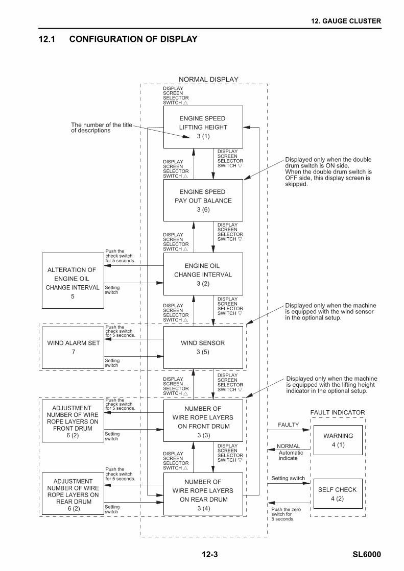
12.1 CONFIGURATION OF DISPLAY
ENGINE SPEED PAY OUT BALANCE
3 (6)
ENGINE OIL CHANGE INTERVAL
3 (2)
WIND SENSOR3 (5)
WIND ALARM SET7
NUMBER OF WIRE ROPE LAYERS
ON FRONT DRUM3 (3)
NUMBER OF WIRE ROPE LAYERS
ON REAR DRUM3 (4)
ALTERATION OF ENGINE OIL
CHANGE INTERVAL5
Push the check switch for 5 seconds.
Push the check switch for 5 seconds.
Push the check switch for 5 seconds.
Push the check switch for 5 seconds.
Setting switch
Setting switch
Setting switch
Setting switch
ADJUSTMENT NUMBER OF WIREROPE LAYERS ON
FRONT DRUM6 (2)
ADJUSTMENT NUMBER OF WIRE ROPE LAYERS ON
REAR DRUM6 (2)
Displayed only when the machineis equipped with the wind sensorin the optional setup.
Displayed only when the doubledrum switch is ON side.When the double drum switch is OFF side, this display screen isskipped.
Displayed only when the machineis equipped with the lifting height indicator in the optional setup.
WARNING4 (1)
SELF CHECK4 (2)
FAULTY
NORMALAutomaticindicate
Setting switch
Push the zero switch for 5 seconds.
The number of the title of descriptions
FAULT INDICATOR
DISPLAYSCREENSELECTOR SWITCH
DISPLAYSCREENSELECTOR SWITCH
DISPLAYSCREENSELECTOR SWITCH
DISPLAYSCREENSELECTOR SWITCH
DISPLAYSCREENSELECTOR SWITCH
DISPLAYSCREENSELECTOR SWITCH
ENGINE SPEED LIFTING HEIGHT
3 (1)
NORMAL DISPLAY
DISPLAYSCREENSELECTOR SWITCH
DISPLAYSCREENSELECTOR SWITCH
DISPLAYSCREENSELECTOR SWITCH
DISPLAYSCREENSELECTOR SWITCH
DISPLAYSCREENSELECTOR SWITCH
12. GAUGE CLUSTER
SL6000 12-4
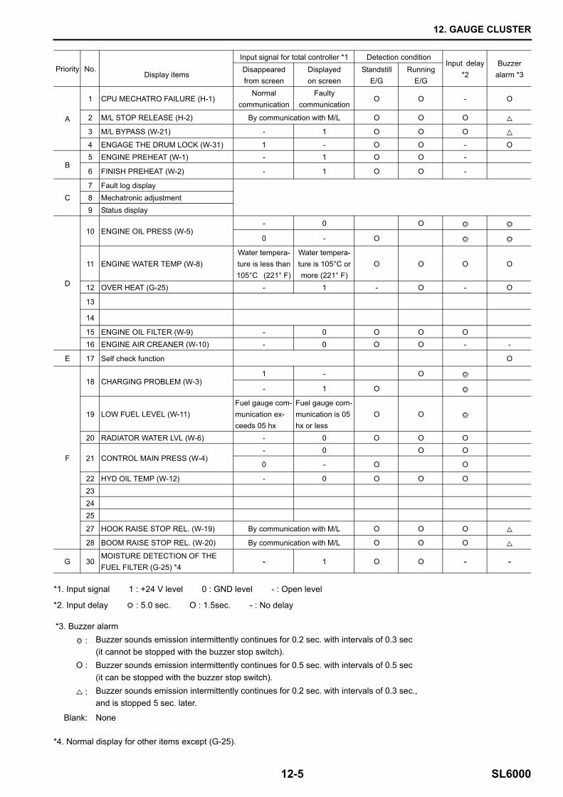
12.2 PRIORITY1. All the display items are divided into seven groups,
A to G.The priority is given to them in the alphabetical or-der, A (highest) to G (lowest).
2. While the items in higher priority groups are dis-played on the screen of the gauge cluster, the items in lower priority groups are not displayed.For example, while the "M/L stop release" (in the group A) is displayed on the screen, the "self check function" (in the ground E) is not displayed. The items in lower priority groups are displayed after the display of the items in higher priority groups is end-ed.
3. When some items in the same group are required to be displayed, they are displayed by turns.
4. The normal display is replaced by the display of the items in higher priority groups, since the normal dis-play has the lowest priority. It can be forcibly dis-played with flashing by pushing the zero switch, and holding it for 5 seconds or longer.
12. GAUGE CLUSTER
12-5 SL6000
*1. Input signal 1 : +24 V level 0 : GND level - : Open level
*2. Input delay : 5.0 sec. O : 1.5sec. - : No delay
*4. Normal display for other items except (G-25).
Priority No.
Display items
Input signal for total controller *1 Detection conditionInput delay
*2Buzzer
alarm *3Disappearedfrom screen
Displayed on screen
StandstillE/G
RunningE/G
A
1 CPU MECHATRO FAILURE (H-1)Normal
communicationFaulty
communicationO O - O
2 M/L STOP RELEASE (H-2) By communication with M/L O O O
3 M/L BYPASS (W-21) - 1 O O O
4 ENGAGE THE DRUM LOCK (W-31) 1 - O O - O
B5 ENGINE PREHEAT (W-1) - 1 O O -
6 FINISH PREHEAT (W-2) - 1 O O -
C7 Fault log display8 Mechatronic adjustment9 Status display
D
10 ENGINE OIL PRESS (W-5)- 0 O
0 - O
11 ENGINE WATER TEMP (W-8)Water tempera-ture is less than 105°C (221° F)
Water tempera-ture is 105°C or more (221° F)
O O O O
12 OVER HEAT (G-25) - 1 - O - O
13
14
15 ENGINE OIL FILTER (W-9) - 0 O O O16 ENGINE AIR CREANER (W-10) - 0 O O - -
E 17 Self check function O
F
18 CHARGING PROBLEM (W-3)1 - O
- 1 O
19 LOW FUEL LEVEL (W-11)Fuel gauge com-munication ex-ceeds 05 hx
Fuel gauge com-munication is 05 hx or less
O O
20 RADIATOR WATER LVL (W-6) - 0 O O O
21 CONTROL MAIN PRESS (W-4)- 0 O O
0 - O O
22 HYD OIL TEMP (W-12) - 0 O O O232425
27 HOOK RAISE STOP REL. (W-19) By communication with M/L O O O
28 BOOM RAISE STOP REL. (W-20) By communication with M/L O O O
G 30MOISTURE DETECTION OF THE FUEL FILTER (G-25) *4
- 1 O O - -
*3. Buzzer alarm
: Buzzer sounds emission intermittently continues for 0.2 sec. with intervals of 0.3 sec (it cannot be stopped with the buzzer stop switch).
O : Buzzer sounds emission intermittently continues for 0.5 sec. with intervals of 0.5 sec (it can be stopped with the buzzer stop switch).
: Buzzer sounds emission intermittently continues for 0.2 sec. with intervals of 0.3 sec., and is stopped 5 sec. later.
Blank: None
12. GAUGE CLUSTER
SL6000 12-6
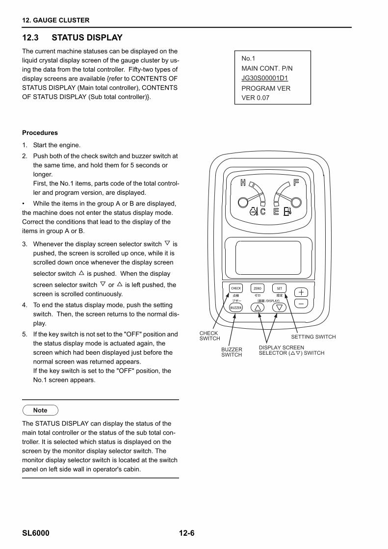
12.3 STATUS DISPLAY
Procedures
The current machine statuses can be displayed on the liquid crystal display screen of the gauge cluster by us-ing the data from the total controller. Fifty-two types of display screens are available {refer to CONTENTS OF STATUS DISPLAY (Main total controller), CONTENTS OF STATUS DISPLAY (Sub total controller)}.
1. Start the engine.
2. Push both of the check switch and buzzer switch at the same time, and hold them for 5 seconds or longer.First, the No.1 items, parts code of the total control-ler and program version, are displayed.
• While the items in the group A or B are displayed, the machine does not enter the status display mode. Correct the conditions that lead to the display of the items in group A or B.
3. Whenever the display screen selector switch is pushed, the screen is scrolled up once, while it is scrolled down once whenever the display screen
selector switch is pushed. When the display
screen selector switch or is left pushed, the screen is scrolled continuously.
4. To end the status display mode, push the setting switch. Then, the screen returns to the normal dis-play.
5. If the key switch is not set to the "OFF" position and the status display mode is actuated again, the screen which had been displayed just before the normal screen was returned appears.If the key switch is set to the "OFF" position, the No.1 screen appears.
The STATUS DISPLAY can display the status of the main total controller or the status of the sub total con-troller. It is selected which status is displayed on the screen by the monitor display selector switch. The monitor display selector switch is located at the switch panel on left side wall in operator's cabin.
No.1MAIN CONT. P/N
PROGRAM VERVER 0.07
JG30S00001D1
SETTING SWITCH
DISPLAY SCREENSELECTOR ( ) SWITCH
CHECKSWITCH
BUZZERSWITCH
12. GAUGE CLUSTER
12-7 SL6000
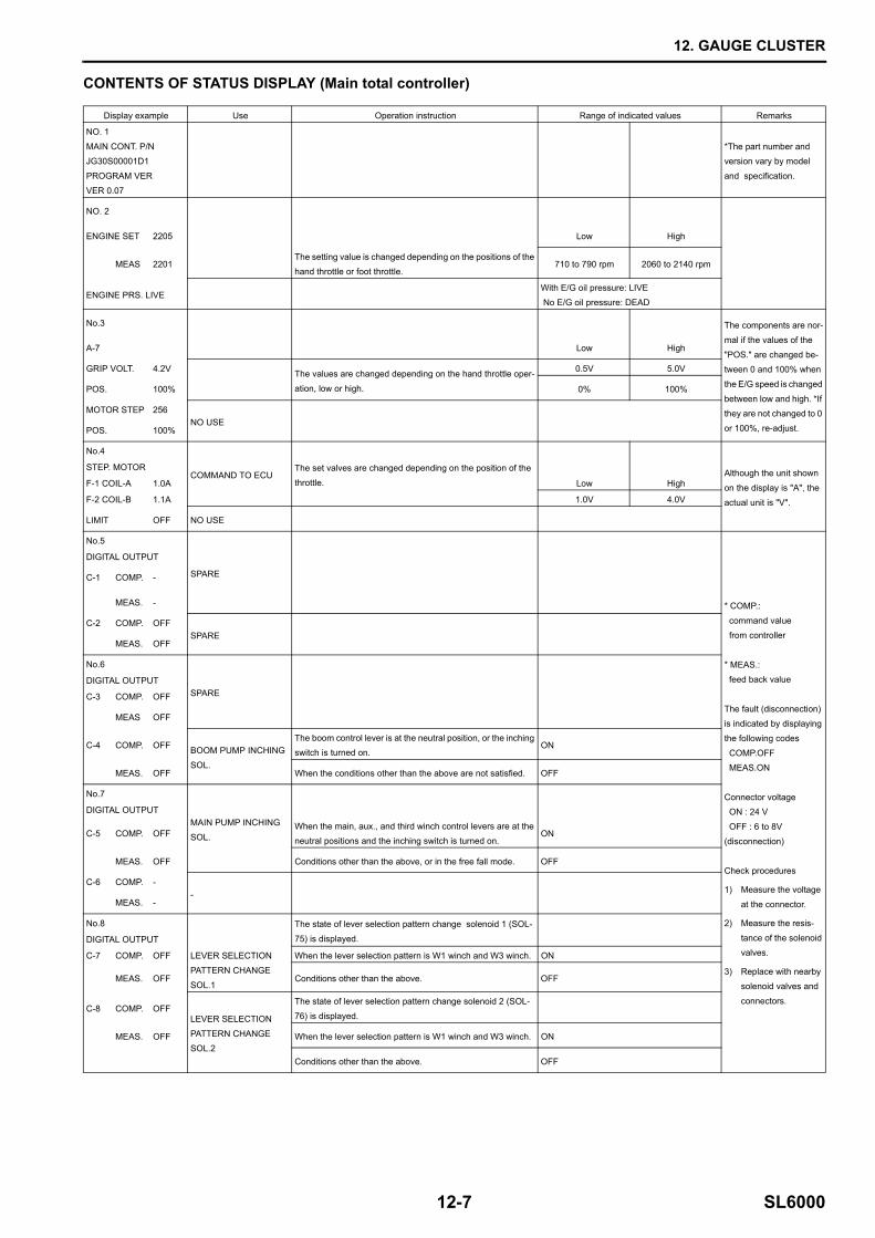
CONTENTS OF STATUS DISPLAY (Main total controller)
Display example Use Operation instruction Range of indicated values Remarks
NO. 1
MAIN CONT. P/NJG30S00001D1
PROGRAM VER
VER 0.07
*The part number and version vary by model
and specification.
NO. 2
ENGINE SET 2205 Low High
MEAS 2201The setting value is changed depending on the positions of the hand throttle or foot throttle.
710 to 790 rpm 2060 to 2140 rpm
ENGINE PRS. LIVEWith E/G oil pressure: LIVE No E/G oil pressure: DEAD
No.3 The components are nor-
mal if the values of the
"POS." are changed be-tween 0 and 100% when
the E/G speed is changed
between low and high. *If they are not changed to 0
or 100%, re-adjust.
A-7 Low High
GRIP VOLT. 4.2V The values are changed depending on the hand throttle oper-
ation, low or high.
0.5V 5.0V
POS. 100% 0% 100%
MOTOR STEP 256NO USE
POS. 100%
No.4
COMMAND TO ECUThe set valves are changed depending on the position of the
throttle. Low HighAlthough the unit shown
on the display is "A", the
actual unit is "V".
STEP. MOTOR
F-1 COIL-A 1.0A
F-2 COIL-B 1.1A 1.0V 4.0V
LIMIT OFF NO USE
No.5
SPARE
* COMP.:
command value from controller
* MEAS.: feed back value
The fault (disconnection) is indicated by displaying
the following codes
COMP.OFF MEAS.ON
Connector voltage ON : 24 V
OFF : 6 to 8V
(disconnection)
Check procedures
1) Measure the voltage
at the connector.
2) Measure the resis-
tance of the solenoid
valves.
3) Replace with nearby solenoid valves and
connectors.
DIGITAL OUTPUT
C-1 COMP. -
MEAS. -
C-2 COMP. OFFSPARE
MEAS. OFF
No.6
SPAREDIGITAL OUTPUT
C-3 COMP. OFF
MEAS OFF
C-4 COMP. OFF BOOM PUMP INCHING
SOL.
The boom control lever is at the neutral position, or the inching switch is turned on.
ON
MEAS. OFF When the conditions other than the above are not satisfied. OFF
No.7
MAIN PUMP INCHING
SOL.
DIGITAL OUTPUT
C-5 COMP. OFFWhen the main, aux., and third winch control levers are at the neutral positions and the inching switch is turned on.
ON
MEAS. OFF Conditions other than the above, or in the free fall mode. OFF
C-6 COMP. --
MEAS. -
No.8 The state of lever selection pattern change solenoid 1 (SOL-
75) is displayed.DIGITAL OUTPUT
C-7 COMP. OFF LEVER SELECTION
PATTERN CHANGE
SOL.1
When the lever selection pattern is W1 winch and W3 winch. ON
MEAS. OFF Conditions other than the above. OFF
C-8 COMP. OFFLEVER SELECTION
PATTERN CHANGESOL.2
The state of lever selection pattern change solenoid 2 (SOL-
76) is displayed.
MEAS. OFF When the lever selection pattern is W1 winch and W3 winch. ON
Conditions other than the above. OFF
12. GAUGE CLUSTER
SL6000 12-8
Display example Use Operation instruction Range of indicated values Remarks
NO. 9
DIGITAL OUTPUT
-
* COMP.:
command value from controller
* MEAS.: feed back value
The fault (disconnection) is indicated by displaying
the following codes
COMP.OFF MEAS.ON
Connector voltage ON : 24 V
OFF : 6 to 8V
(disconnection)
Check procedures
1) Measure the voltage
at the connector.
2) Measure the resis-
tance of the solenoid
valves.
3) Replace with nearby solenoid valves and
connectors.
C-9 COMP.
MEAS.
C-10 COMP. OFFSPARE
MEAS. OFF
NO. 10
DIGITAL OUTPUT
NO USEC-11 COMP. OFF
MEAS. OFF
C-12 COMP. -
MEAS.
NO.11
DIGITAL OUTPUT
SPAREC-13 COMP. OFF
MEAS. OFF
C-14 COMP. OFFSPARE
MEAS. OFF
NO.12
DIGITAL OUTPUT
H1 WINCH MOTOR BOOST SOL.
Status of the H1 winch motor boost solenoid valve (SOL-15) is
displayed.
C-15 COMP. OFF The H1 winch lever is at the neutral position. ON
MEAS. OFF The H1 winch lever is not at the neutral position. OFF
When the H1 winch lever is returned to the neutral position.The code is changed to the "ON" 1 sec. later (If the lever is not at the neutral position within
1 sec., the "OFF" code remains displayed.)
C-16 COMP. OFF
H2 WINCH MOTOR
BOOST SOL.
Status of the H2 winch motor boost solenoid valve (SOL-16) is
displayed.
MEAS. OFF The H2 winch lever is at the neutral position. ON
The H2 winch lever is not at the neutral position. OFF
When the H2 winch lever is returned to the neutral position.The code is changed to the "ON" 1 sec. later (If the lever is not at the neutral position within
1 sec., the "OFF" code remains displayed.)
NO.13
DIGITAL OUTPUT
W1 WINCH MOTOR
BOOST SOL.
Status of the W1 winch motor boost solenoid valve (SOL-19) is
displayed.
C-17 COMP. OFF The W1 winch lever is at the neutral position. ON
MEAS. OFF The W1 winch lever is not at the neutral position. OFF
When the W1 winch lever is returned to the neutral position.
The code is changed to the "ON" 1 sec. later
(If the lever is not at the neutral position within 1 sec., the "OFF" code remains displayed.)
C-18 COMP. OFF
H1 WINCH TURN GRIP
Motion of the H1 winch drum turn detection grip is displayed. Display of the "ON" and "OFF" is repeated with the drum rotation. The repeating speed of the
"ON" and "OFF" codes display is proportional
to the drum rotation speed.MEAS. OFF Turn on the drum turn switch, and raise or lower the H1 winch.
12. GAUGE CLUSTER
12-9 SL6000
Display example Use Operation instruction Range of indicated values Remarks
NO.14
DIGITAL OUTPUTH2 WINCH TURN GRIP
Display of the "ON" and "OFF" is repeated with the drum rotation. The repeating speed of the
"ON" and "OFF" codes display is proportional
to the drum rotation speed.
* COMP.:
command value
from controller
* MEAS.:
feed back value
The fault (disconnection)
is indicated by displaying
the following codes COMP.OFF
MEAS.ON
Connector voltage
ON : 24 V
OFF : 6 to 8V(disconnection)
Check procedures
1) Measure the voltage at the connector.
2) Measure the resis-
tance of the solenoid valves.
3) Replace with nearby
solenoid valves and
connectors.
C-19 COMP. OFF Motion of the H2 winch drum turn detection grip is displayed.
MEAS. OFF Turn on the drum turn switch, and raise or lower the H2 winch.
C-20 COMP. OFFSPARE
MEAS. OFF
NO.15
DIGITAL OUTPUT
SPAREC-21 COMP. OFF
MEAS. OFF
C-22 COMP. OFFSPARE
MEAS. OFF
NO.16
DIGITAL OUTPUT
C-23 COMP.SPARE
MEAS.
C-24 COMP. SPARE
MEAS.
NO.17
DIGITAL OUTPUT
C-25 COMP.SPARE
MEAS.
C-26 COMP. OFF LEVER SELECTION PATTERN INDICATOR
LAMP (W1 & W3)
When the lever selection pattern is W1 winch and W3 winch. ON
MEAS. OFF conditions other than the above. OFF
NO.18
DIGITAL OUTPUT LEVER SELECTION
PATTERN INDICATOR
LAMP(W2 & W3)C-27 COMP. OFF When the lever selection pattern is W2 winch and W3 winch. ON
MEAS. OFF conditions other than the above. OFF
C-28 COMP. LEVER SELECTION PATTERN INDICATOR
LAMP(W1 & W2)
When the lever selection pattern is W1 winch and W2 winch. ON
MEAS. conditions other than the above. OFF
12. GAUGE CLUSTER
SL6000 12-10
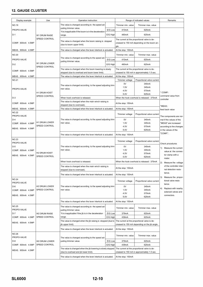
Display example Use Operation instruction Range of indicated values Remarks
NO.19
W1 DRUM RAISE
SPEED CONTROL
The value is changed according to the speed ad-
justing trimmer value.
*It is inapplicable if the boom is in the deceleration range.
Trimmer min. value Trimmer max. value
PROPO-VALVE E/G Low 410mA 625mA
* COMP.:command value from
controller
*MEAS.:
feed back value
The components are nor-
mal if the values of the
"MEAS" are increased according to the changes
in the values of the
"COMP.".
Check procedures
1) Measure the current value at the connec-
tor clamp with a
meter.
2) Measure the voltage of the controller inter-
nal detection resis-
tance.
3) Measure the propor-
tional valve resis-
tance.
4) Replace with nearby solenoid valves and
connectors.
D-1 E/G High 460mA 625mA
COMP. 600mA 4.5MPThe value is changed when the boom raising is stopped
(due to boom upper limit).
The current at the proportional valve is de-
creased to 150 mA depending on the boom an-gle.
MEAS. 600mA 4.5MP The value is changed when the lever interlock is actuated. At the stop: 150mA
NO.20
W1 DRUM LOWER SPEED CONTROL
The value is changed according to the speed ad-
justing trimmer value.
Trimmer min. value Trimmer max. value
PROPO-VALVE E/G Low 410mA 625mA
D-2 E/G High 460mA 625mA
COMP. 600mA 4.5MPThe value is changed when the boom lowering is slowly stopped (due to overload and boom lower limit).
The current at the proportional valve is de-creased to 150 mA in approximately 1.5 sec.
MEAS. 600mA 4.5MP The value is changed when the lever interlock is actuated. At the stop: 150mA
NO.21
H1 DRUM HOIST
SPEED CONTROL
The value is changed according to the speed adjusting trim-mer value.
Trimmer voltage Proportional valve current
PROPO-VALVE
0V1.5V
4.5V
5.0V
345mA345mA
570mA
625mA
D-3 When hook overhoist is released. When the hook overhoist is released : 375mA
COMP. 600mA 4.5MPThe value is changed when the main winch raising is
stopped (due to overroast).At the stop: 150mA
MEAS. 600mA 4.5MP The value is changed when the lever interlock is actuated. At the stop: 150mA
NO.22PROPO-VALVE
H1 DRUM LOWER
SPEED CONTROL
The value is changed according to the speed adjusting trim-
mer value.
Trimmer voltage Proportional valve current
D-4 0V1.5V
4.5V
5.0V
345mA345mA
570mA
625mA
COMP. 600mA 4.5MP
MEAS. 600mA 4.5MP
The value is changed when the lever interlock is actuated. At the stop: 150mA
NO.23
PROPO-VALVE
The value is changed according to the speed adjusting trim-
mer value.
Trimmer voltage Proportional valve current
D-5
H2 DRUM HOIST
SPEED CONTROL
0V
1.5V
4.5V5.0V
345mA
345mA
570mA625mA
COMP. 600mA 4.5MP
MEAS. 600mA 4.5MP
When hook overhoist is released. When the hook overhoist is released : 375mA
The value is changed when the main winch raising is stopped (due to overroast).
At the stop: 150mA
The value is changed when the lever interlock is actuated. At the stop: 150mA
NO.24
PROPO-VALVE
H2 DRUM LOWER SPEED CONTROL
The value is changed according to the speed adjusting trim-mer value.
Trimmer voltage Proportional valve current
D-6 0V
1.5V4.5V
5.0V
345mA
345mA570mA
625mA
COMP. 600mA 4.5MP
MEAS. 600mA 4.5MP
The value is changed when the lever interlock is actuated. At the stop: 150mA
NO.25PROPO-VALVE
W2 DRUM RAISE
SPEED CONTROL
The value is changed according to the speed ad-
justing trimmer value.
*It is inapplicable if the jib is in the deceleration range.
Trimmer min. value Trimmer max. value
D-7 E/G Low 379mA 625mA
COMP. 600mA 4.5MP E/G High 439mA 625mA
MEAS. 600mA 4.5MPThe value is changed when the jib raising is stopped (due to
jib upper limit).
The current at the proportional valve is de-
creased to 150 mA depending on the jib angle.
The value is changed when the lever interlock is actuated. At the stop: 150mA
NO.26PROPO-VALVE
W2 DRUM LOWER
SPEED CONTROL
The value is changed according to the speed ad-
justing trimmer value.
Trimmer min. value Trimmer max. value
D-8 E/G Low 379mA 625mA
COMP. 600mA 4.5MP E/G High 439mA 625mA
MEAS. 600mA 4.5MPThe value is changed when the jib lowering is slowly stopped
(due to overload and jib lower limit).
The current at the proportional valve is de-
creased to 150 mA in approximately 1.5 sec.
The value is changed when the lever interlock is actuated. At the stop: 150mA
12. GAUGE CLUSTER
12-11 SL6000
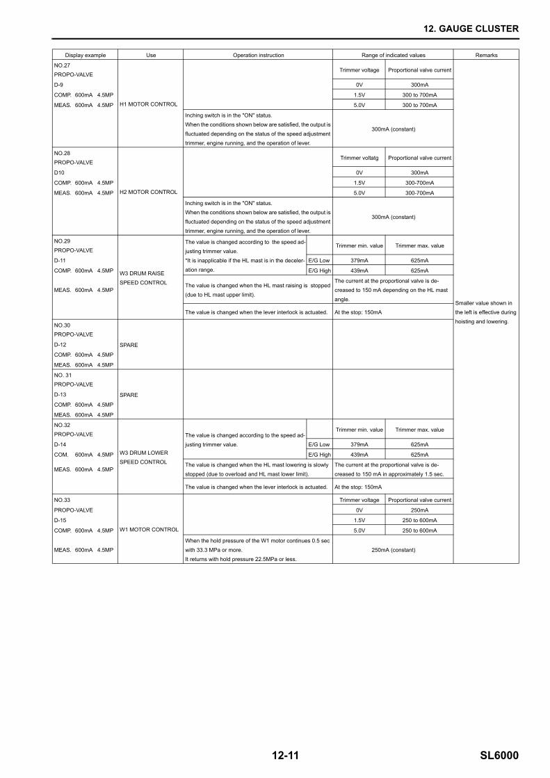
Display example Use Operation instruction Range of indicated values Remarks
NO.27
PROPO-VALVE
H1 MOTOR CONTROL
Trimmer voltage Proportional valve current
Smaller value shown in the left is effective during
hoisting and lowering.
D-9 0V 300mA
COMP. 600mA 4.5MP 1.5V 300 to 700mA
MEAS. 600mA 4.5MP 5.0V 300 to 700mA
Inching switch is in the "ON" status.
When the conditions shown below are satisfied, the output is
fluctuated depending on the status of the speed adjustment trimmer, engine running, and the operation of lever.
300mA (constant)
NO.28PROPO-VALVE
H2 MOTOR CONTROL
Trimmer voltatg Proportional valve current
D10 0V 300mA
COMP. 600mA 4.5MP 1.5V 300-700mA
MEAS. 600mA 4.5MP 5.0V 300-700mA
Inching switch is in the "ON" status.When the conditions shown below are satisfied, the output is
fluctuated depending on the status of the speed adjustment
trimmer, engine running, and the operation of lever.
300mA (constant)
NO.29
PROPO-VALVE
W3 DRUM RAISE
SPEED CONTROL
The value is changed according to the speed ad-justing trimmer value.
*It is inapplicable if the HL mast is in the deceler-
ation range.
Trimmer min. value Trimmer max. value
D-11 E/G Low 379mA 625mA
COMP. 600mA 4.5MP E/G High 439mA 625mA
MEAS. 600mA 4.5MPThe value is changed when the HL mast raising is stopped
(due to HL mast upper limit).
The current at the proportional valve is de-creased to 150 mA depending on the HL mast
angle.
The value is changed when the lever interlock is actuated. At the stop: 150mA
NO.30PROPO-VALVE
SPARED-12
COMP. 600mA 4.5MP
MEAS. 600mA 4.5MP
NO. 31PROPO-VALVE
SPARED-13
COMP. 600mA 4.5MP
MEAS. 600mA 4.5MP
NO.32PROPO-VALVE
W3 DRUM LOWER SPEED CONTROL
The value is changed according to the speed ad-
justing trimmer value.
Trimmer min. value Trimmer max. value
D-14 E/G Low 379mA 625mA
COM. 600mA 4.5MP E/G High 439mA 625mA
MEAS. 600mA 4.5MPThe value is changed when the HL mast lowering is slowly
stopped (due to overload and HL mast lower limit).
The current at the proportional valve is de-
creased to 150 mA in approximately 1.5 sec.
The value is changed when the lever interlock is actuated. At the stop: 150mA
NO.33
W1 MOTOR CONTROL
Trimmer voltage Proportional valve current
PROPO-VALVE 0V 250mA
D-15 1.5V 250 to 600mA
COMP. 600mA 4.5MP 5.0V 250 to 600mA
MEAS. 600mA 4.5MP
When the hold pressure of the W1 motor continues 0.5 sec
with 33.3 MPa or more.It returns with hold pressure 22.5MPa or less.
250mA (constant)
12. GAUGE CLUSTER
SL6000 12-12
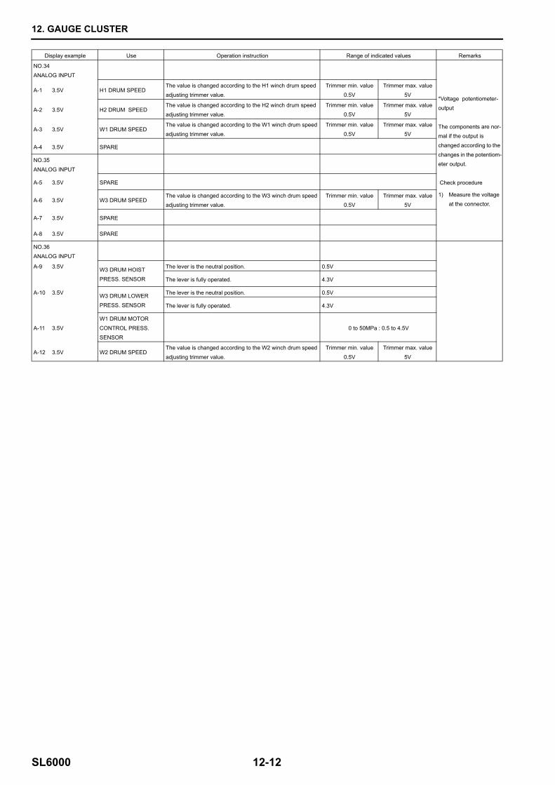
Display example Use Operation instruction Range of indicated values Remarks
NO.34
ANALOG INPUT
*Voltage potentiometer-output
The components are nor-mal if the output is
changed according to the
changes in the potentiom-eter output.
Check procedure
1) Measure the voltage at the connector.
A-1 3.5V H1 DRUM SPEEDThe value is changed according to the H1 winch drum speed
adjusting trimmer value.
Trimmer min. value
0.5V
Trimmer max. value
5V
A-2 3.5V H2 DRUM SPEEDThe value is changed according to the H2 winch drum speed
adjusting trimmer value.
Trimmer min. value
0.5V
Trimmer max. value
5V
A-3 3.5V W1 DRUM SPEEDThe value is changed according to the W1 winch drum speed
adjusting trimmer value.
Trimmer min. value
0.5V
Trimmer max. value
5V
A-4 3.5V SPARE
NO.35
ANALOG INPUT
A-5 3.5V SPARE
A-6 3.5V W3 DRUM SPEEDThe value is changed according to the W3 winch drum speed adjusting trimmer value.
Trimmer min. value0.5V
Trimmer max. value5V
A-7 3.5V SPARE
A-8 3.5V SPARE
NO.36
ANALOG INPUT
A-9 3.5V W3 DRUM HOIST
PRESS. SENSOR
The lever is the neutral position. 0.5V
The lever is fully operated. 4.3V
A-10 3.5V W3 DRUM LOWER
PRESS. SENSOR
The lever is the neutral position. 0.5V
The lever is fully operated. 4.3V
A-11 3.5V
W1 DRUM MOTOR
CONTROL PRESS.
SENSOR
0 to 50MPa : 0.5 to 4.5V
A-12 3.5V W2 DRUM SPEEDThe value is changed according to the W2 winch drum speed
adjusting trimmer value.
Trimmer min. value
0.5V
Trimmer max. value
5V
12. GAUGE CLUSTER
12-13 SL6000
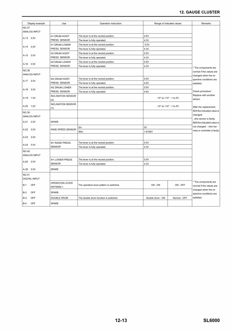
Display example Use Operation instruction Range of indicated values Remarks
NO.37
ANALOG INPUT
* The components are
normal if the values are changed when the re-
spective conditions are
satisfied.
Check procedure:
Replace with another sensor.
After the replacement.ÅEif the indicated value is
changed:
→the sensor is faulty. ÅEif the indicated value is
not changed: →the har-
ness or controller is faulty.
A-13 3.5VH1 DRUM HOISTPRESS. SENSOR
The lever is at the neutral position. 0.5V
The lever is fully operated. 4.3V
A-14 3.5VH1 DRUM LOWER
PRESS. SENSOR
The lever is at the neutral position. 0.5V
The lever is fully operated. 4.3V
A-15 3.5VH2 DRUM HOIST
PRESS. SENSOR
The lever is at the neutral position. 0.5V
The lever is fully operated. 4.3V
A-16 3.5VH2 DRUM LOWERPRESS. SENSOR
The lever is at the neutral position. 0.5V
The lever is fully operated. 4.3V
NO.38
ANALOG INPUT
A-17 3.5VW2 DRUM HOIST
PRESS. SENSOR
The lever is at the neutral position. 0.5V
The lever is fully operated. 4.6V
A-18 3.5VW2 DRUM LOWER
PRESS. SENSOR
The lever is at the neutral position. 0.5V
The lever is fully operated. 4.6V
A-19 1.5VINCLINATION SENSOR
(X)-10° to +10° : 1 to 5V
A-20 1.5VINCLINATION SENSOR
(Y)-10° to +10° : 1 to 5V
NO.39
ANALOG INPUT
A-21 3.5V SPARE
A-22 3.5V WIND SPEED SENSOR0m 0V
90m 1.6195V
A-23 3.5V -
A-24 3.5VW1 RAISE PRESS. SENSOR
The lever is at the neutral position. 0.5V
The lever is fully operated. 4.3V
NO.40
ANALOG INPUT
A-25 3.5VW1 LOWER PRESS. SENSOR
The lever is at the neutral position. 0.5V
The lever is fully operated. 4.3V
A-26 3.5V SPARE
NO.41
DIGITAL INPUT* The components are
normal if the values are changed when the re-
spective conditions are
satisfied.
B-1 OFFOPERATION LEVER
PATTERN 1The operation lever pattern is switched. ON : ON ON : OFF
B-2 OFF SPARE
B-3 OFF DOUBLE DRUM The double drum function is switched. Double drum : ON Normal : OFF
B-4 OFF SPARE
12. GAUGE CLUSTER
SL6000 12-14
Display example Use Operation instruction Range of indicated values Remarks
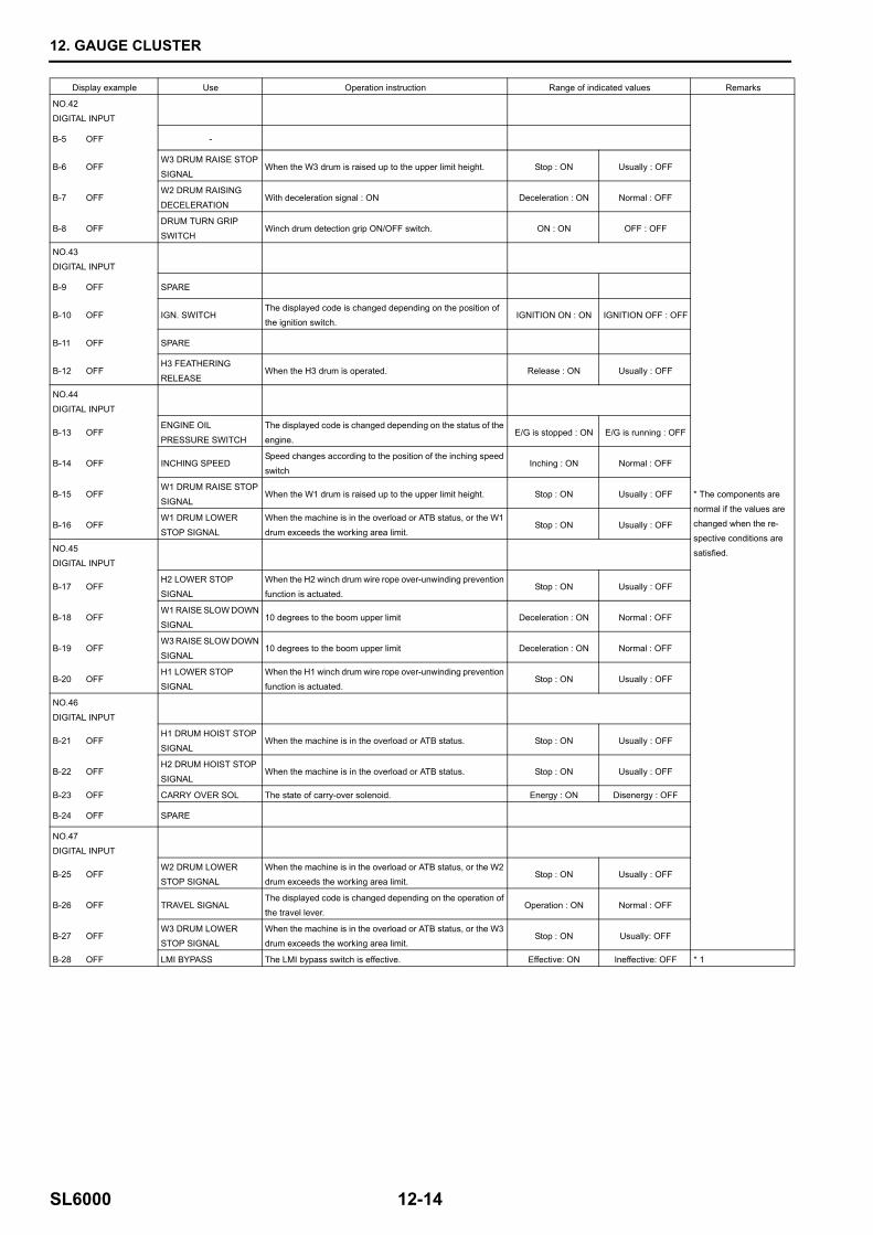
NO.42
DIGITAL INPUT
* The components are
normal if the values are
changed when the re-spective conditions are
satisfied.
B-5 OFF -
B-6 OFFW3 DRUM RAISE STOP
SIGNALWhen the W3 drum is raised up to the upper limit height. Stop : ON Usually : OFF
B-7 OFFW2 DRUM RAISING
DECELERATIONWith deceleration signal : ON Deceleration : ON Normal : OFF
B-8 OFFDRUM TURN GRIP
SWITCHWinch drum detection grip ON/OFF switch. ON : ON OFF : OFF
NO.43
DIGITAL INPUT
B-9 OFF SPARE
B-10 OFF IGN. SWITCHThe displayed code is changed depending on the position of the ignition switch.
IGNITION ON : ON IGNITION OFF : OFF
B-11 OFF SPARE
B-12 OFFH3 FEATHERING
RELEASEWhen the H3 drum is operated. Release : ON Usually : OFF
NO.44
DIGITAL INPUT
B-13 OFFENGINE OIL
PRESSURE SWITCH
The displayed code is changed depending on the status of the
engine.E/G is stopped : ON E/G is running : OFF
B-14 OFF INCHING SPEEDSpeed changes according to the position of the inching speed
switchInching : ON Normal : OFF
B-15 OFFW1 DRUM RAISE STOP
SIGNALWhen the W1 drum is raised up to the upper limit height. Stop : ON Usually : OFF
B-16 OFFW1 DRUM LOWER
STOP SIGNAL
When the machine is in the overload or ATB status, or the W1
drum exceeds the working area limit.Stop : ON Usually : OFF
NO.45
DIGITAL INPUT
B-17 OFFH2 LOWER STOP
SIGNAL
When the H2 winch drum wire rope over-unwinding prevention
function is actuated.Stop : ON Usually : OFF
B-18 OFFW1 RAISE SLOW DOWN
SIGNAL10 degrees to the boom upper limit Deceleration : ON Normal : OFF
B-19 OFFW3 RAISE SLOW DOWN
SIGNAL10 degrees to the boom upper limit Deceleration : ON Normal : OFF
B-20 OFFH1 LOWER STOP
SIGNAL
When the H1 winch drum wire rope over-unwinding prevention
function is actuated.Stop : ON Usually : OFF
NO.46
DIGITAL INPUT
B-21 OFFH1 DRUM HOIST STOP
SIGNALWhen the machine is in the overload or ATB status. Stop : ON Usually : OFF
B-22 OFFH2 DRUM HOIST STOP
SIGNALWhen the machine is in the overload or ATB status. Stop : ON Usually : OFF
B-23 OFF CARRY OVER SOL The state of carry-over solenoid. Energy : ON Disenergy : OFF
B-24 OFF SPARE
NO.47DIGITAL INPUT
B-25 OFFW2 DRUM LOWER STOP SIGNAL
When the machine is in the overload or ATB status, or the W2 drum exceeds the working area limit.
Stop : ON Usually : OFF
B-26 OFF TRAVEL SIGNALThe displayed code is changed depending on the operation of the travel lever.
Operation : ON Normal : OFF
B-27 OFFW3 DRUM LOWER STOP SIGNAL
When the machine is in the overload or ATB status, or the W3 drum exceeds the working area limit.
Stop : ON Usually: OFF
B-28 OFF LMI BYPASS The LMI bypass switch is effective. Effective: ON Ineffective: OFF * 1
12. GAUGE CLUSTER
12-15 SL6000
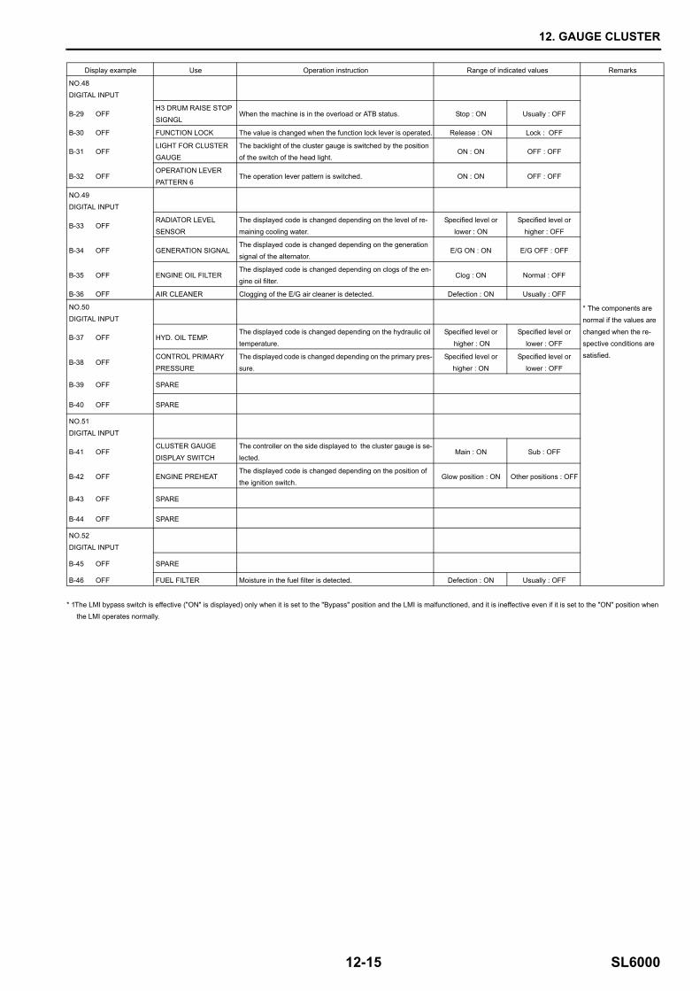
* 1The LMI bypass switch is effective ("ON" is displayed) only when it is set to the "Bypass" position and the LMI is malfunctioned, and it is ineffective even if it is set to the "ON" position when the LMI operates normally.
Display example Use Operation instruction Range of indicated values Remarks
NO.48
DIGITAL INPUT
* The components are
normal if the values are
changed when the re-spective conditions are
satisfied.
B-29 OFFH3 DRUM RAISE STOP
SIGNGLWhen the machine is in the overload or ATB status. Stop : ON Usually : OFF
B-30 OFF FUNCTION LOCK The value is changed when the function lock lever is operated. Release : ON Lock : OFF
B-31 OFFLIGHT FOR CLUSTER GAUGE
The backlight of the cluster gauge is switched by the position of the switch of the head light.
ON : ON OFF : OFF
B-32 OFFOPERATION LEVER PATTERN 6
The operation lever pattern is switched. ON : ON OFF : OFF
NO.49DIGITAL INPUT
B-33 OFFRADIATOR LEVEL SENSOR
The displayed code is changed depending on the level of re-maining cooling water.
Specified level or lower : ON
Specified level or higher : OFF
B-34 OFF GENERATION SIGNALThe displayed code is changed depending on the generation signal of the alternator.
E/G ON : ON E/G OFF : OFF
B-35 OFF ENGINE OIL FILTERThe displayed code is changed depending on clogs of the en-gine oil filter.
Clog : ON Normal : OFF
B-36 OFF AIR CLEANER Clogging of the E/G air cleaner is detected. Defection : ON Usually : OFF
NO.50
DIGITAL INPUT
B-37 OFF HYD. OIL TEMP.The displayed code is changed depending on the hydraulic oil
temperature.
Specified level or
higher : ON
Specified level or
lower : OFF
B-38 OFFCONTROL PRIMARY
PRESSURE
The displayed code is changed depending on the primary pres-
sure.
Specified level or
higher : ON
Specified level or
lower : OFF
B-39 OFF SPARE
B-40 OFF SPARE
NO.51
DIGITAL INPUT
B-41 OFFCLUSTER GAUGE
DISPLAY SWITCH
The controller on the side displayed to the cluster gauge is se-
lected. Main : ON Sub : OFF
B-42 OFF ENGINE PREHEATThe displayed code is changed depending on the position of the ignition switch.
Glow position : ON Other positions : OFF
B-43 OFF SPARE
B-44 OFF SPARE
NO.52
DIGITAL INPUT
B-45 OFF SPARE
B-46 OFF FUEL FILTER Moisture in the fuel filter is detected. Defection : ON Usually : OFF
12. GAUGE CLUSTER
SL6000 12-16
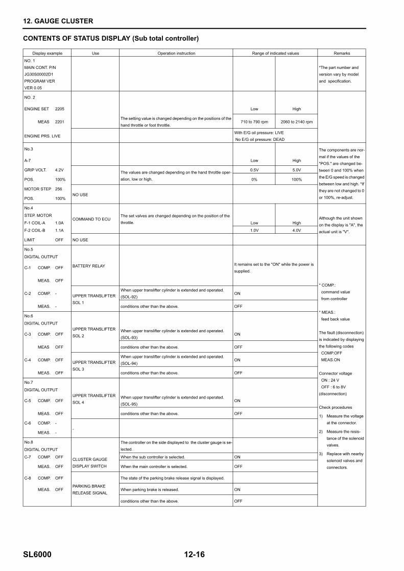
CONTENTS OF STATUS DISPLAY (Sub total controller)
Display example Use Operation instruction Range of indicated values Remarks
NO. 1
MAIN CONT. P/NJG30S00002D1
PROGRAM VER
VER 0.05
*The part number and version vary by model
and specification.
NO. 2
ENGINE SET 2205 Low High
MEAS 2201The setting value is changed depending on the positions of the hand throttle or foot throttle.
710 to 790 rpm 2060 to 2140 rpm
ENGINE PRS. LIVEWith E/G oil pressure: LIVE No E/G oil pressure: DEAD
No.3 The components are nor-
mal if the values of the
"POS." are changed be-tween 0 and 100% when
the E/G speed is changed
between low and high. *If they are not changed to 0
or 100%, re-adjust.
A-7 Low High
GRIP VOLT. 4.2V The values are changed depending on the hand throttle oper-
ation, low or high.
0.5V 5.0V
POS. 100% 0% 100%
MOTOR STEP 256NO USE
POS. 100%
No.4
COMMAND TO ECUThe set valves are changed depending on the position of the
throttle. Low HighAlthough the unit shown
on the display is "A", the
actual unit is "V".
STEP. MOTOR
F-1 COIL-A 1.0A
F-2 COIL-B 1.1A 1.0V 4.0V
LIMIT OFF NO USE
No.5
BATTERY RELAY
* COMP.:
command value
from controller
* MEAS.:
feed back value
The fault (disconnection)
is indicated by displaying
the following codes COMP.OFF
MEAS.ON
Connector voltage
ON : 24 V
OFF : 6 to 8V(disconnection)
Check procedures
1) Measure the voltage at the connector.
2) Measure the resis-
tance of the solenoid valves.
3) Replace with nearby
solenoid valves and
connectors.
DIGITAL OUTPUT
C-1 COMP. OFFIt remains set to the "ON" while the power is supplied.
MEAS. OFF
C-2 COMP. - UPPER TRANSLIFTER
SOL 1
When upper translifter cylinder is extended and operated. (SOL-92)
ON
MEAS. - conditions other than the above. OFF
No.6
UPPER TRANSLIFTER
SOL 2
DIGITAL OUTPUT
C-3 COMP. OFFWhen upper translifter cylinder is extended and operated. (SOL-93)
ON
MEAS OFF conditions other than the above. OFF
C-4 COMP. OFF UPPER TRANSLIFTER SOL 3
When upper translifter cylinder is extended and operated.
(SOL-94)ON
MEAS. OFF conditions other than the above. OFF
No.7
UPPER TRANSLIFTER
SOL 4
DIGITAL OUTPUT
C-5 COMP. OFFWhen upper translifter cylinder is extended and operated.
(SOL-95)ON
MEAS. OFF conditions other than the above. OFF
C-6 COMP. --
MEAS. -
No.8 The controller on the side displayed to the cluster gauge is se-
lected. DIGITAL OUTPUT
C-7 COMP. OFF CLUSTER GAUGE DISPLAY SWITCH
When the sub controller is selected. ON
MEAS. OFF When the main controller is selected. OFF
C-8 COMP. OFF
PARKING BRAKE RELEASE SIGNAL
The state of the parking brake release signal is displayed.
MEAS. OFF When parking brake is released. ON
conditions other than the above. OFF
12. GAUGE CLUSTER
12-17 SL6000
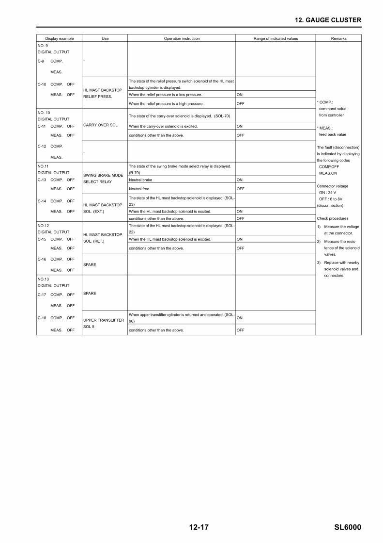
Display example Use Operation instruction Range of indicated values Remarks
NO. 9
DIGITAL OUTPUT
-
* COMP.:
command value from controller
* MEAS.: feed back value
The fault (disconnection) is indicated by displaying
the following codes
COMP.OFF MEAS.ON
Connector voltage ON : 24 V
OFF : 6 to 8V
(disconnection)
Check procedures
1) Measure the voltage
at the connector.
2) Measure the resis-tance of the solenoid
valves.
3) Replace with nearby
solenoid valves and connectors.
C-9 COMP.
MEAS.
C-10 COMP. OFFHL MAST BACKSTOP
RELIEF PRESS.
The state of the relief pressure switch solenoid of the HL mast backstop cylinder is displayed.
MEAS. OFF When the relief pressure is a low pressure. ON
When the relief pressure is a high pressure. OFF
NO. 10
DIGITAL OUTPUTCARRY OVER SOL
The state of the carry-over solenoid is displayed. (SOL-70)
C-11 COMP. OFF When the carry-over solenoid is excited. ON
MEAS. OFF conditions other than the above. OFF
C-12 COMP. -
MEAS.
NO.11
DIGITAL OUTPUTSWING BRAKE MODE SELECT RELAY
The state of the swing brake mode select relay is displayed.
(R-79)
C-13 COMP. OFF Neutral brake ON
MEAS. OFF Neutral free OFF
C-14 COMP. OFFHL MAST BACKSTOP
SOL. (EXT.)
The state of the HL mast backstop solenoid is displayed. (SOL-
23)
MEAS. OFF When the HL mast backstop solenoid is excited. ON
conditions other than the above. OFF
NO.12DIGITAL OUTPUT
HL MAST BACKSTOP
SOL. (RET.)
The state of the HL mast backstop solenoid is displayed. (SOL-22)
C-15 COMP. OFF When the HL mast backstop solenoid is excited. ON
MEAS. OFF conditions other than the above. OFF
C-16 COMP. OFFSPARE
MEAS. OFF
NO.13DIGITAL OUTPUT
SPAREC-17 COMP. OFF
MEAS. OFF
C-18 COMP. OFF UPPER TRANSLIFTER SOL 5
When upper translifter cylinder is returned and operated. (SOL-
96)ON
MEAS. OFF conditions other than the above. OFF
12. GAUGE CLUSTER
SL6000 12-18
Display example Use Operation instruction Range of indicated values Remarks
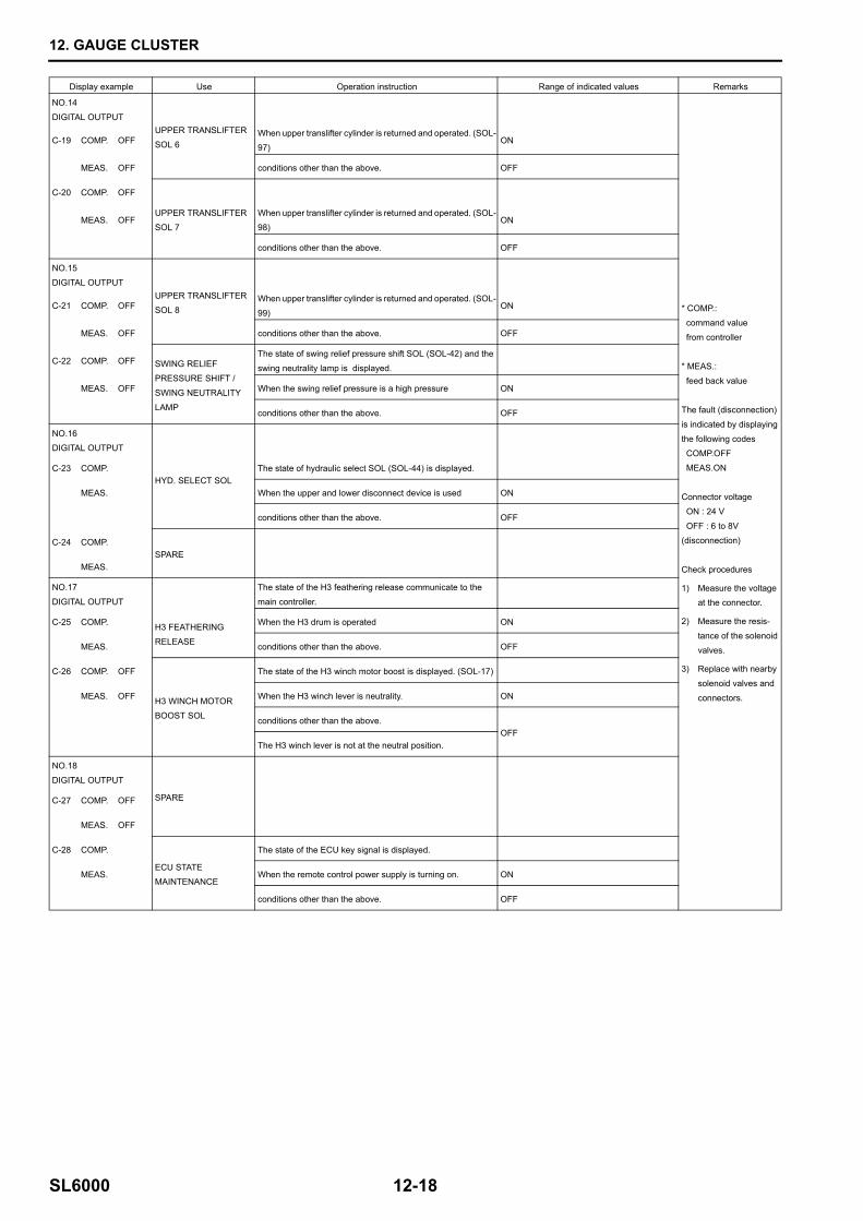
NO.14
DIGITAL OUTPUTUPPER TRANSLIFTER SOL 6
* COMP.: command value
from controller
* MEAS.:
feed back value
The fault (disconnection)
is indicated by displaying
the following codes COMP.OFF
MEAS.ON
Connector voltage
ON : 24 V
OFF : 6 to 8V(disconnection)
Check procedures
1) Measure the voltage at the connector.
2) Measure the resis-
tance of the solenoid
valves.
3) Replace with nearby
solenoid valves and
connectors.
C-19 COMP. OFFWhen upper translifter cylinder is returned and operated. (SOL-
97)ON
MEAS. OFF conditions other than the above. OFF
C-20 COMP. OFF
UPPER TRANSLIFTER SOL 7
MEAS. OFFWhen upper translifter cylinder is returned and operated. (SOL-98)
ON
conditions other than the above. OFF
NO.15
DIGITAL OUTPUTUPPER TRANSLIFTER SOL 8C-21 COMP. OFF
When upper translifter cylinder is returned and operated. (SOL-
99)ON
MEAS. OFF conditions other than the above. OFF
C-22 COMP. OFF SWING RELIEF PRESSURE SHIFT /
SWING NEUTRALITY
LAMP
The state of swing relief pressure shift SOL (SOL-42) and the
swing neutrality lamp is displayed.
MEAS. OFF When the swing relief pressure is a high pressure ON
conditions other than the above. OFF
NO.16DIGITAL OUTPUT
C-23 COMP.HYD. SELECT SOL
The state of hydraulic select SOL (SOL-44) is displayed.
MEAS. When the upper and lower disconnect device is used ON
conditions other than the above. OFF
C-24 COMP.SPARE
MEAS.
NO.17
DIGITAL OUTPUT
The state of the H3 feathering release communicate to the
main controller.
C-25 COMP. H3 FEATHERING
RELEASE
When the H3 drum is operated ON
MEAS. conditions other than the above. OFF
C-26 COMP. OFF
H3 WINCH MOTOR BOOST SOL
The state of the H3 winch motor boost is displayed. (SOL-17)
MEAS. OFF When the H3 winch lever is neutrality. ON
conditions other than the above.OFF
The H3 winch lever is not at the neutral position.
NO.18
DIGITAL OUTPUT
SPAREC-27 COMP. OFF
MEAS. OFF
C-28 COMP.
ECU STATE MAINTENANCE
The state of the ECU key signal is displayed.
MEAS. When the remote control power supply is turning on. ON
conditions other than the above. OFF
12. GAUGE CLUSTER
12-19 SL6000
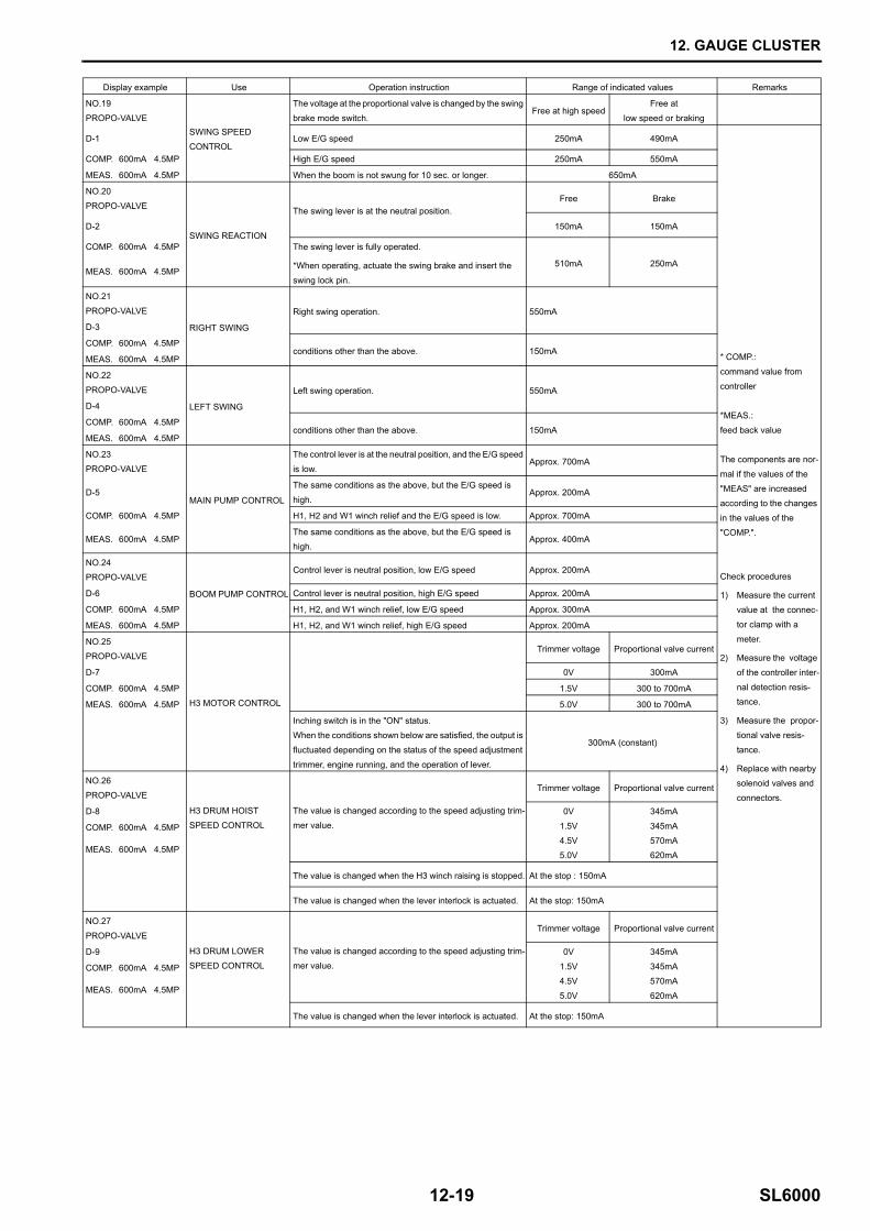
Display example Use Operation instruction Range of indicated values Remarks
NO.19
PROPO-VALVESWING SPEED
CONTROL
The voltage at the proportional valve is changed by the swing
brake mode switch.Free at high speed
Free at
low speed or braking
D-1 Low E/G speed 250mA 490mA
* COMP.:
command value from
controller
*MEAS.:
feed back value
The components are nor-
mal if the values of the
"MEAS" are increased according to the changes
in the values of the
"COMP.".
Check procedures
1) Measure the current
value at the connec-
tor clamp with a
meter.
2) Measure the voltage
of the controller inter-
nal detection resis-tance.
3) Measure the propor-
tional valve resis-
tance.
4) Replace with nearby solenoid valves and
connectors.
COMP. 600mA 4.5MP High E/G speed 250mA 550mA
MEAS. 600mA 4.5MP When the boom is not swung for 10 sec. or longer. 650mA
NO.20
PROPO-VALVE
SWING REACTION
The swing lever is at the neutral position.Free Brake
D-2 150mA 150mA
COMP. 600mA 4.5MP The swing lever is fully operated.
*When operating, actuate the swing brake and insert the
swing lock pin.
510mA 250mAMEAS. 600mA 4.5MP
NO.21
PROPO-VALVE
RIGHT SWING
Right swing operation. 550mA
D-3
COMP. 600mA 4.5MPconditions other than the above. 150mA
MEAS. 600mA 4.5MP
NO.22
PROPO-VALVE
LEFT SWING
Left swing operation. 550mA
D-4
COMP. 600mA 4.5MPconditions other than the above. 150mA
MEAS. 600mA 4.5MP
NO.23
PROPO-VALVE
MAIN PUMP CONTROL
The control lever is at the neutral position, and the E/G speed
is low.Approx. 700mA
D-5The same conditions as the above, but the E/G speed is
high.Approx. 200mA
COMP. 600mA 4.5MP H1, H2 and W1 winch relief and the E/G speed is low. Approx. 700mA
MEAS. 600mA 4.5MPThe same conditions as the above, but the E/G speed is high.
Approx. 400mA
NO.24PROPO-VALVE
BOOM PUMP CONTROL
Control lever is neutral position, low E/G speed Approx. 200mA
D-6 Control lever is neutral position, high E/G speed Approx. 200mA
COMP. 600mA 4.5MP H1, H2, and W1 winch relief, low E/G speed Approx. 300mA
MEAS. 600mA 4.5MP H1, H2, and W1 winch relief, high E/G speed Approx. 200mA
NO.25PROPO-VALVE
H3 MOTOR CONTROL
Trimmer voltage Proportional valve current
D-7 0V 300mA
COMP. 600mA 4.5MP 1.5V 300 to 700mA
MEAS. 600mA 4.5MP 5.0V 300 to 700mA
Inching switch is in the "ON" status. When the conditions shown below are satisfied, the output is
fluctuated depending on the status of the speed adjustment
trimmer, engine running, and the operation of lever.
300mA (constant)
NO.26
PROPO-VALVE
H3 DRUM HOIST
SPEED CONTROL
The value is changed according to the speed adjusting trim-
mer value.
Trimmer voltage Proportional valve current
D-8 0V
1.5V
4.5V5.0V
345mA
345mA
570mA620mA
COMP. 600mA 4.5MP
MEAS. 600mA 4.5MP
The value is changed when the H3 winch raising is stopped. At the stop : 150mA
The value is changed when the lever interlock is actuated. At the stop: 150mA
NO.27
PROPO-VALVE
H3 DRUM LOWER SPEED CONTROL
The value is changed according to the speed adjusting trim-mer value.
Trimmer voltage Proportional valve current
D-9 0V
1.5V4.5V
5.0V
345mA
345mA570mA
620mA
COMP. 600mA 4.5MP
MEAS. 600mA 4.5MP
The value is changed when the lever interlock is actuated. At the stop: 150mA
12. GAUGE CLUSTER
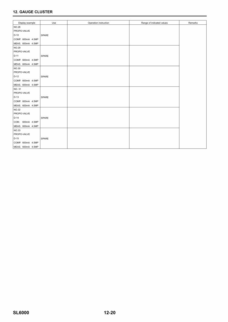
SL6000 12-20
Display example Use Operation instruction Range of indicated values Remarks
NO.28
PROPO-VALVE
SPARED-10
COMP. 600mA 4.5MP
MEAS. 600mA 4.5MP
NO.29
PROPO-VALVE
SPARED-11
COMP. 600mA 4.5MP
MEAS. 600mA 4.5MP
NO.30
PROPO-VALVE
SPARED-12
COMP. 600mA 4.5MP
MEAS. 600mA 4.5MP
NO. 31
PROPO-VALVE
SPARED-13
COMP. 600mA 4.5MP
MEAS. 600mA 4.5MP
NO.32
PROPO-VALVE
SPARED-14
COM. 600mA 4.5MP
MEAS. 600mA 4.5MP
NO.33
PROPO-VALVE
SPARED-15
COMP. 600mA 4.5MP
MEAS. 600mA 4.5MP
12. GAUGE CLUSTER
12-21 SL6000
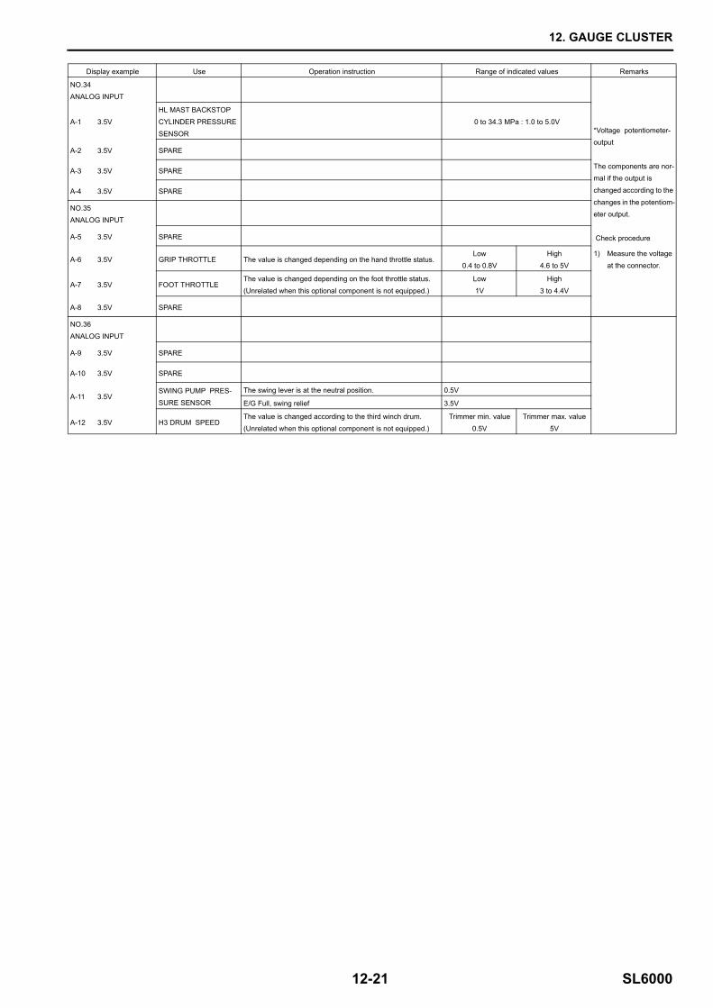
Display example Use Operation instruction Range of indicated values Remarks
NO.34
ANALOG INPUT
*Voltage potentiometer-output
The components are nor-mal if the output is
changed according to the
changes in the potentiom-eter output.
Check procedure
1) Measure the voltage at the connector.
A-1 3.5V
HL MAST BACKSTOP
CYLINDER PRESSURE
SENSOR
0 to 34.3 MPa : 1.0 to 5.0V
A-2 3.5V SPARE
A-3 3.5V SPARE
A-4 3.5V SPARE
NO.35ANALOG INPUT
A-5 3.5V SPARE
A-6 3.5V GRIP THROTTLE The value is changed depending on the hand throttle status.Low
0.4 to 0.8VHigh
4.6 to 5V
A-7 3.5V FOOT THROTTLEThe value is changed depending on the foot throttle status.
(Unrelated when this optional component is not equipped.)
Low
1V
High
3 to 4.4V
A-8 3.5V SPARE
NO.36
ANALOG INPUT
A-9 3.5V SPARE
A-10 3.5V SPARE
A-11 3.5VSWING PUMP PRES-
SURE SENSOR
The swing lever is at the neutral position. 0.5V
E/G Full, swing relief 3.5V
A-12 3.5V H3 DRUM SPEEDThe value is changed according to the third winch drum.
(Unrelated when this optional component is not equipped.)
Trimmer min. value
0.5V
Trimmer max. value
5V
12. GAUGE CLUSTER
SL6000 12-22
Display example Use Operation instruction Range of indicated values Remarks
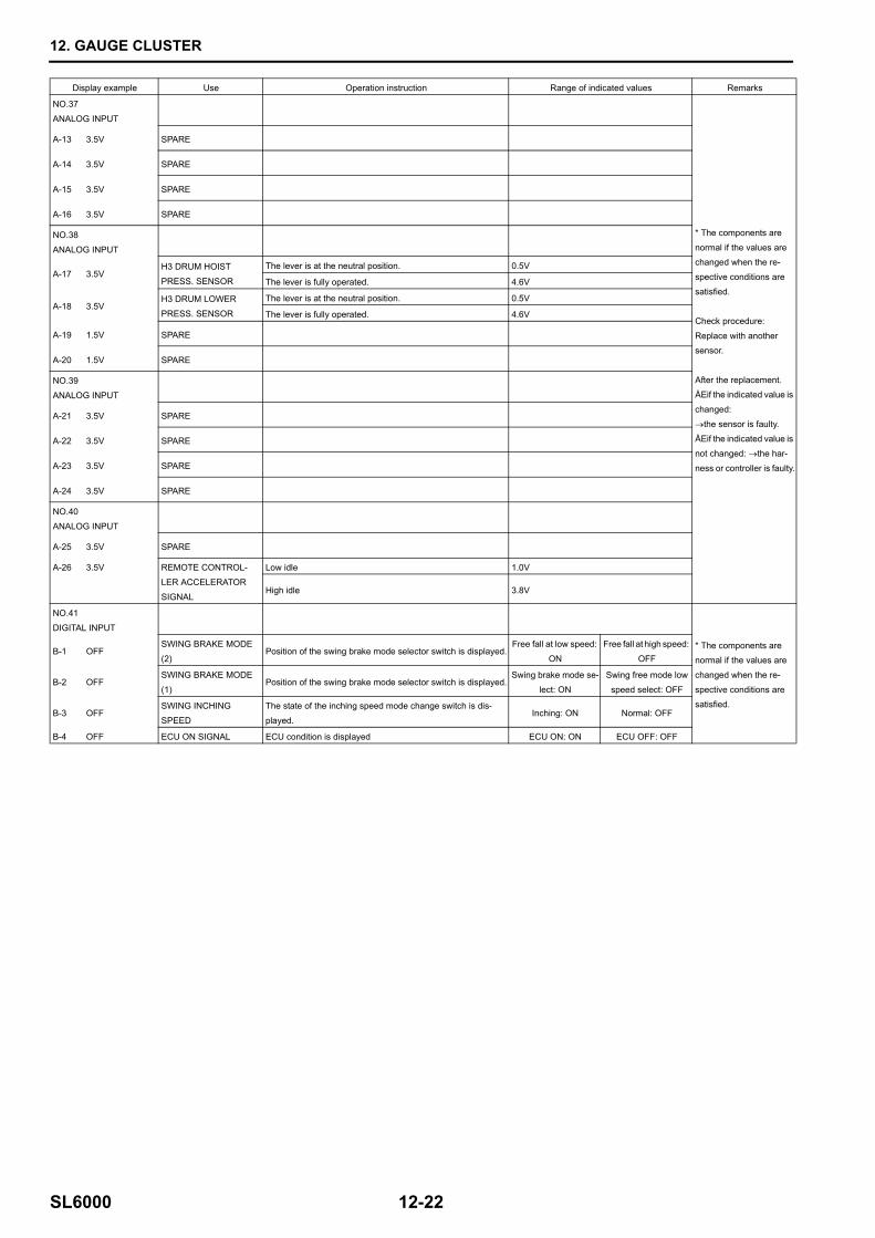
NO.37
ANALOG INPUT
* The components are
normal if the values are changed when the re-
spective conditions are
satisfied.
Check procedure:
Replace with another sensor.
After the replacement.ÅEif the indicated value is
changed:
→the sensor is faulty. ÅEif the indicated value is
not changed: →the har-
ness or controller is faulty.
A-13 3.5V SPARE
A-14 3.5V SPARE
A-15 3.5V SPARE
A-16 3.5V SPARE
NO.38
ANALOG INPUT
A-17 3.5VH3 DRUM HOIST
PRESS. SENSOR
The lever is at the neutral position. 0.5V
The lever is fully operated. 4.6V
A-18 3.5VH3 DRUM LOWER
PRESS. SENSOR
The lever is at the neutral position. 0.5V
The lever is fully operated. 4.6V
A-19 1.5V SPARE
A-20 1.5V SPARE
NO.39
ANALOG INPUT
A-21 3.5V SPARE
A-22 3.5V SPARE
A-23 3.5V SPARE
A-24 3.5V SPARE
NO.40
ANALOG INPUT
A-25 3.5V SPARE
A-26 3.5V REMOTE CONTROL-
LER ACCELERATOR
SIGNAL
Low idle 1.0V
High idle 3.8V
NO.41
DIGITAL INPUT
* The components are normal if the values are
changed when the re-
spective conditions are satisfied.
B-1 OFFSWING BRAKE MODE
(2)Position of the swing brake mode selector switch is displayed.
Free fall at low speed:
ON
Free fall at high speed:
OFF
B-2 OFFSWING BRAKE MODE
(1)Position of the swing brake mode selector switch is displayed.
Swing brake mode se-
lect: ON
Swing free mode low
speed select: OFF
B-3 OFFSWING INCHING
SPEED
The state of the inching speed mode change switch is dis-
played.Inching: ON Normal: OFF
B-4 OFF ECU ON SIGNAL ECU condition is displayed ECU ON: ON ECU OFF: OFF
12. GAUGE CLUSTER
12-23 SL6000
Display example Use Operation instruction Range of indicated values Remarks
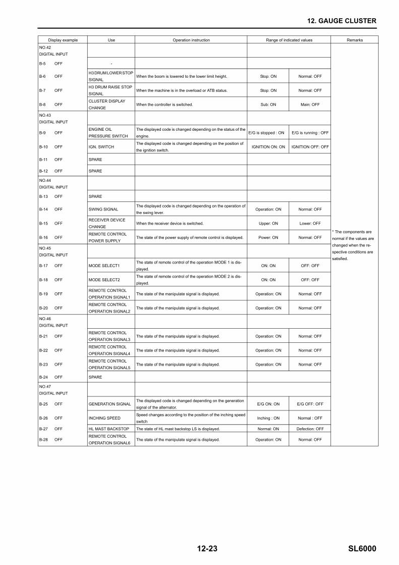
NO.42
DIGITAL INPUT
* The components are
normal if the values are changed when the re-
spective conditions are
satisfied.
B-5 OFF -
B-6 OFFH3 DRUM LOWER STOP
SIGNALWhen the boom is lowered to the lower limit height. Stop: ON Normal: OFF
B-7 OFFH3 DRUM RAISE STOP
SIGNALWhen the machine is in the overload or ATB status. Stop: ON Normal: OFF
B-8 OFFCLUSTER DISPLAY
CHANGEWhen the controller is switched. Sub: ON Main: OFF
NO.43
DIGITAL INPUT
B-9 OFFENGINE OIL
PRESSURE SWITCH
The displayed code is changed depending on the status of the
engine.E/G is stopped : ON E/G is running : OFF
B-10 OFF IGN. SWITCHThe displayed code is changed depending on the position of
the ignition switch.IGNITION ON: ON IGNITION OFF: OFF
B-11 OFF SPARE
B-12 OFF SPARE
NO.44
DIGITAL INPUT
B-13 OFF SPARE
B-14 OFF SWING SIGNALThe displayed code is changed depending on the operation of
the swing lever.Operation: ON Normal: OFF
B-15 OFFRECEIVER DEVICE
CHANGEWhen the receiver device is switched. Upper: ON Lower: OFF
B-16 OFFREMOTE CONTROL
POWER SUPPLYThe state of the power supply of remote control is displayed. Power: ON Normal: OFF
NO.45
DIGITAL INPUT
B-17 OFF MODE SELECT1The state of remote control of the operation MODE 1 is dis-
played.ON: ON OFF: OFF
B-18 OFF MODE SELECT2The state of remote control of the operation MODE 2 is dis-
played.ON: ON OFF: OFF
B-19 OFFREMOTE CONTROL
OPERATION SIGNAL1The state of the manipulate signal is displayed. Operation: ON Normal: OFF
B-20 OFFREMOTE CONTROL
OPERATION SIGNAL2The state of the manipulate signal is displayed. Operation: ON Normal: OFF
NO.46
DIGITAL INPUT
B-21 OFFREMOTE CONTROL
OPERATION SIGNAL3The state of the manipulate signal is displayed. Operation: ON Normal: OFF
B-22 OFFREMOTE CONTROL
OPERATION SIGNAL4The state of the manipulate signal is displayed. Operation: ON Normal: OFF
B-23 OFFREMOTE CONTROL
OPERATION SIGNAL5The state of the manipulate signal is displayed. Operation: ON Normal: OFF
B-24 OFF SPARE
NO.47DIGITAL INPUT
B-25 OFF GENERATION SIGNALThe displayed code is changed depending on the generation signal of the alternator.
E/G ON: ON E/G OFF: OFF
B-26 OFF INCHING SPEEDSpeed changes according to the position of the inching speed switch
Inching : ON Normal : OFF
B-27 OFF HL MAST BACKSTOP The state of HL mast backstop LS is displayed. Normal: ON Defection: OFF
B-28 OFFREMOTE CONTROL
OPERATION SIGNAL6The state of the manipulate signal is displayed. Operation: ON Normal: OFF
12. GAUGE CLUSTER
SL6000 12-24
Display example Use Operation instruction Range of indicated values Remarks
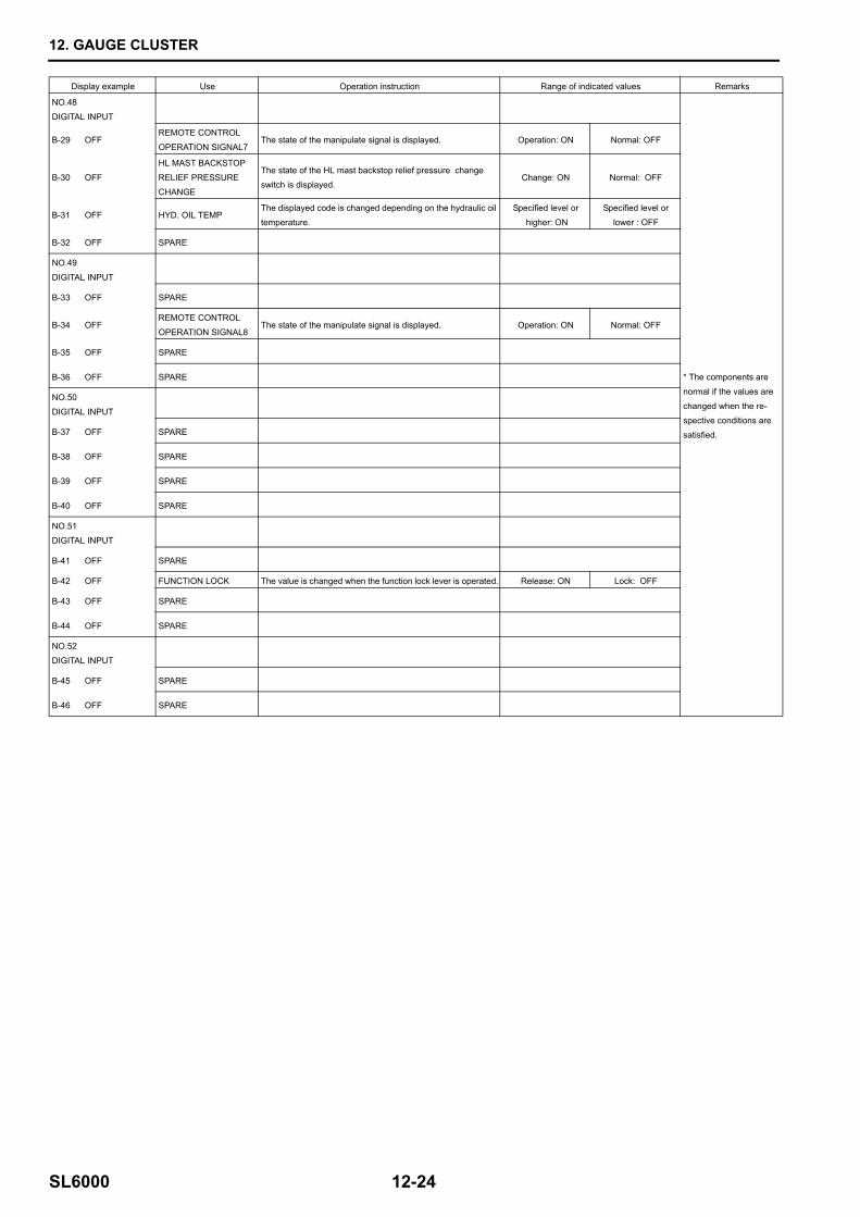
NO.48
DIGITAL INPUT
* The components are
normal if the values are
changed when the re-spective conditions are
satisfied.
B-29 OFFREMOTE CONTROL
OPERATION SIGNAL7The state of the manipulate signal is displayed. Operation: ON Normal: OFF
B-30 OFF
HL MAST BACKSTOP
RELIEF PRESSURE
CHANGE
The state of the HL mast backstop relief pressure change switch is displayed.
Change: ON Normal: OFF
B-31 OFF HYD. OIL TEMPThe displayed code is changed depending on the hydraulic oil
temperature.
Specified level or
higher: ON
Specified level or
lower : OFF
B-32 OFF SPARE
NO.49
DIGITAL INPUT
B-33 OFF SPARE
B-34 OFFREMOTE CONTROL
OPERATION SIGNAL8The state of the manipulate signal is displayed. Operation: ON Normal: OFF
B-35 OFF SPARE
B-36 OFF SPARE
NO.50
DIGITAL INPUT
B-37 OFF SPARE
B-38 OFF SPARE
B-39 OFF SPARE
B-40 OFF SPARE
NO.51DIGITAL INPUT
B-41 OFF SPARE
B-42 OFF FUNCTION LOCK The value is changed when the function lock lever is operated. Release: ON Lock: OFF
B-43 OFF SPARE
B-44 OFF SPARE
NO.52
DIGITAL INPUT
B-45 OFF SPARE
B-46 OFF SPARE
12. GAUGE CLUSTER
12-25 SL6000
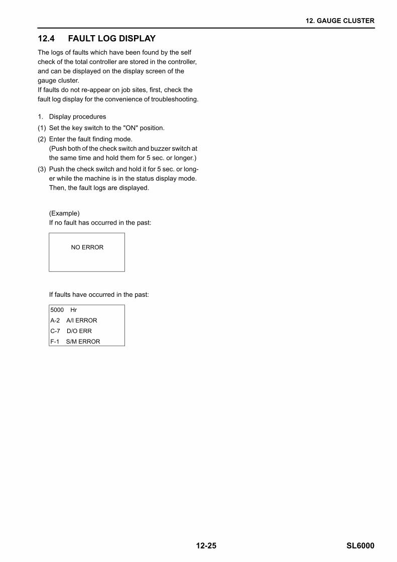
12.4 FAULT LOG DISPLAY
(Example)If no fault has occurred in the past:
If faults have occurred in the past:
The logs of faults which have been found by the self check of the total controller are stored in the controller, and can be displayed on the display screen of the gauge cluster. If faults do not re-appear on job sites, first, check the fault log display for the convenience of troubleshooting.
1. Display procedures
(1) Set the key switch to the "ON" position.
(2) Enter the fault finding mode.(Push both of the check switch and buzzer switch at the same time and hold them for 5 sec. or longer.)
(3) Push the check switch and hold it for 5 sec. or long-er while the machine is in the status display mode. Then, the fault logs are displayed.
NO ERROR
5000 Hr
A-2 A/I ERROR
C-7 D/O ERR
F-1 S/M ERROR
12. GAUGE CLUSTER
SL6000 12-26
(Example) (a)
(b)
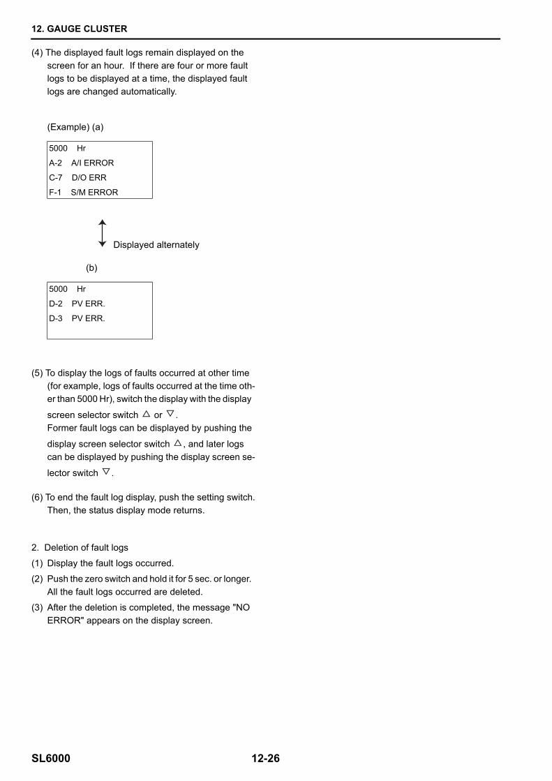
(4) The displayed fault logs remain displayed on the screen for an hour. If there are four or more fault logs to be displayed at a time, the displayed fault logs are changed automatically.
5000 Hr
A-2 A/I ERROR
C-7 D/O ERR
F-1 S/M ERROR
Displayed alternately
5000 Hr
D-2 PV ERR.
D-3 PV ERR.
(5) To display the logs of faults occurred at other time (for example, logs of faults occurred at the time oth-er than 5000 Hr), switch the display with the display
screen selector switch or .Former fault logs can be displayed by pushing the
display screen selector switch , and later logs can be displayed by pushing the display screen se-
lector switch .
(6) To end the fault log display, push the setting switch.Then, the status display mode returns.
2. Deletion of fault logs
(1) Display the fault logs occurred.
(2) Push the zero switch and hold it for 5 sec. or longer. All the fault logs occurred are deleted.
(3) After the deletion is completed, the message "NO ERROR" appears on the display screen.
12. GAUGE CLUSTER
12-27 SL6000
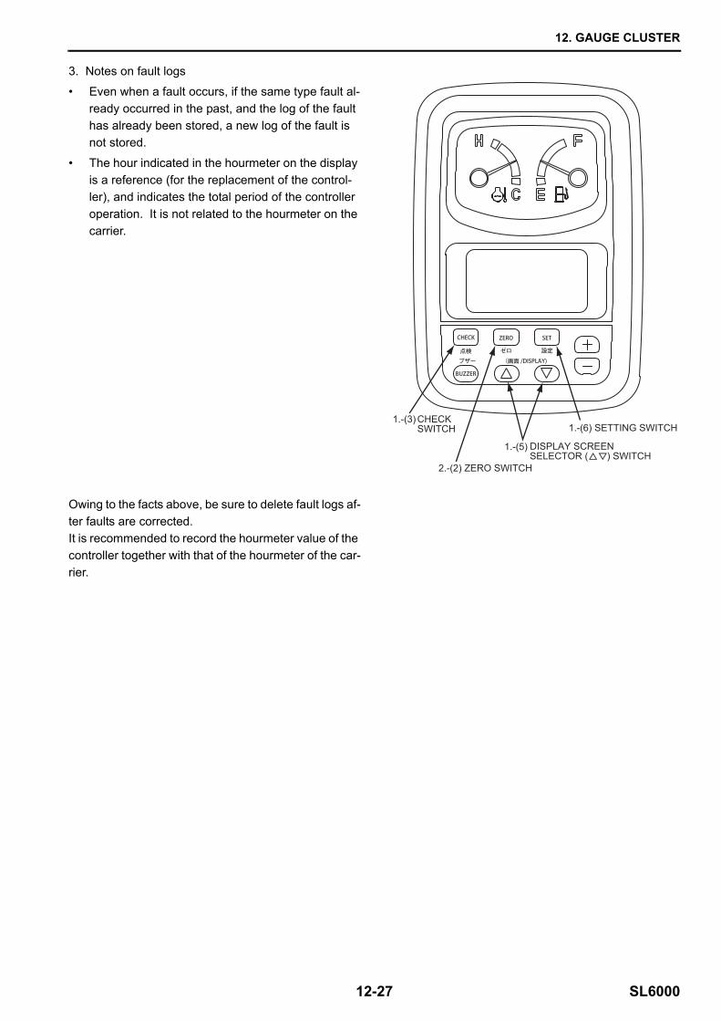
3. Notes on fault logs
• Even when a fault occurs, if the same type fault al-ready occurred in the past, and the log of the fault has already been stored, a new log of the fault is not stored.
• The hour indicated in the hourmeter on the display is a reference (for the replacement of the control-ler), and indicates the total period of the controller operation. It is not related to the hourmeter on the carrier.
Owing to the facts above, be sure to delete fault logs af-ter faults are corrected.It is recommended to record the hourmeter value of the controller together with that of the hourmeter of the car-rier.
1.-(6) SETTING SWITCHCHECKSWITCH
1.-(3)
2.-(2) ZERO SWITCH
DISPLAY SCREENSELECTOR ( ) SWITCH
1.-(5)
12. GAUGE CLUSTER
SL6000 12-28
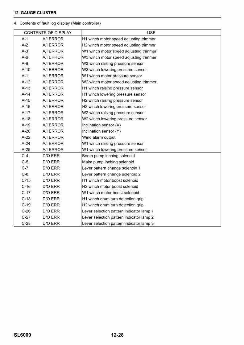
4. Contents of fault log display (Main controller)
CONTENTS OF DISPLAY USEA-1 A/I ERROR H1 winch motor speed adjusting trimmerA-2 A/I ERROR H2 winch motor speed adjusting trimmerA-3 A/I ERROR W1 winch motor speed adjusting trimmerA-6 A/I ERROR W3 winch motor speed adjusting trimmerA-9 A/I ERROR W3 winch raising pressure sensorA-10 A/I ERROR W3 winch lowering pressure sensorA-11 A/I ERROR W1 winch motor pressure sensorA-12 A/I ERROR W2 winch motor speed adjusting trimmerA-13 A/I ERROR H1 winch raising pressure sensorA-14 A/I ERROR H1 winch lowering pressure sensorA-15 A/I ERROR H2 winch raising pressure sensorA-16 A/I ERROR H2 winch lowering pressure sensorA-17 A/I ERROR W2 winch raising pressure sensorA-18 A/I ERROR W2 winch lowering pressure sensorA-19 A/I ERROR Inclination sensor (X)A-20 A/I ERROR Inclination sensor (Y)A-22 A/I ERROR Wind alarm outputA-24 A/I ERROR W1 winch raising pressure sensorA-25 A/I ERROR W1 winch lowering pressure sensorC-4 D/O ERR Boom pump inching solenoidC-5 D/O ERR Maim pump inching solenoidC-7 D/O ERR Lever pattern change solenoid 1C-8 D/O ERR Lever pattern change solenoid 2C-15 D/O ERR H1 winch motor boost solenoidC-16 D/O ERR H2 winch motor boost solenoidC-17 D/O ERR W1 winch motor boost solenoidC-18 D/O ERR H1 winch drum turn detection gripC-19 D/O ERR H2 winch drum turn detection gripC-26 D/O ERR Lever selection pattern indicator lamp 1C-27 D/O ERR Lever selection pattern indicator lamp 2C-28 D/O ERR Lever selection pattern indicator lamp 3
12. GAUGE CLUSTER
12-29 SL6000
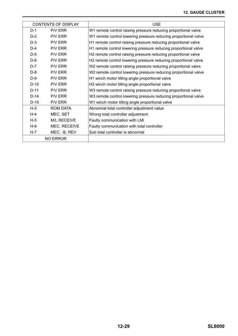
CONTENTS OF DISPLAY USED-1 P/V ERR W1 remote control raising pressure reducing proportional valveD-2 P/V ERR W1 remote control lowering pressure reducing proportional valveD-3 P/V ERR H1 remote control raising pressure reducing proportional valveD-4 P/V ERR H1 remote control lowering pressure reducing proportional valveD-5 P/V ERR H2 remote control raising pressure reducing proportional valveD-6 P/V ERR H2 remote control lowering pressure reducing proportional valveD-7 P/V ERR W2 remote control raising pressure reducing proportional valveD-8 P/V ERR W2 remote control lowering pressure reducing proportional valveD-9 P/V ERR H1 winch motor tilting angle proportional valveD-10 P/V ERR H2 winch motor tilting angle proportional valveD-11 P/V ERR W3 remote control raising pressure reducing proportional valveD-14 P/V ERR W3 remote control lowering pressure reducing proportional valveD-15 P/V ERR W1 winch motor tilting angle proportional valveH-3 ROM DATA Abnormal total controller adjustment valueH-4 MEC. SET Wrong total controller adjustmentH-5 M/L RECEIVE Faulty communication with LMiH-6 MEC. RECEIVE Faulty communication with total controllerH-7 MEC. -B. REV Sub total controller is abnormal
NO ERROR
12. GAUGE CLUSTER
SL6000 12-30
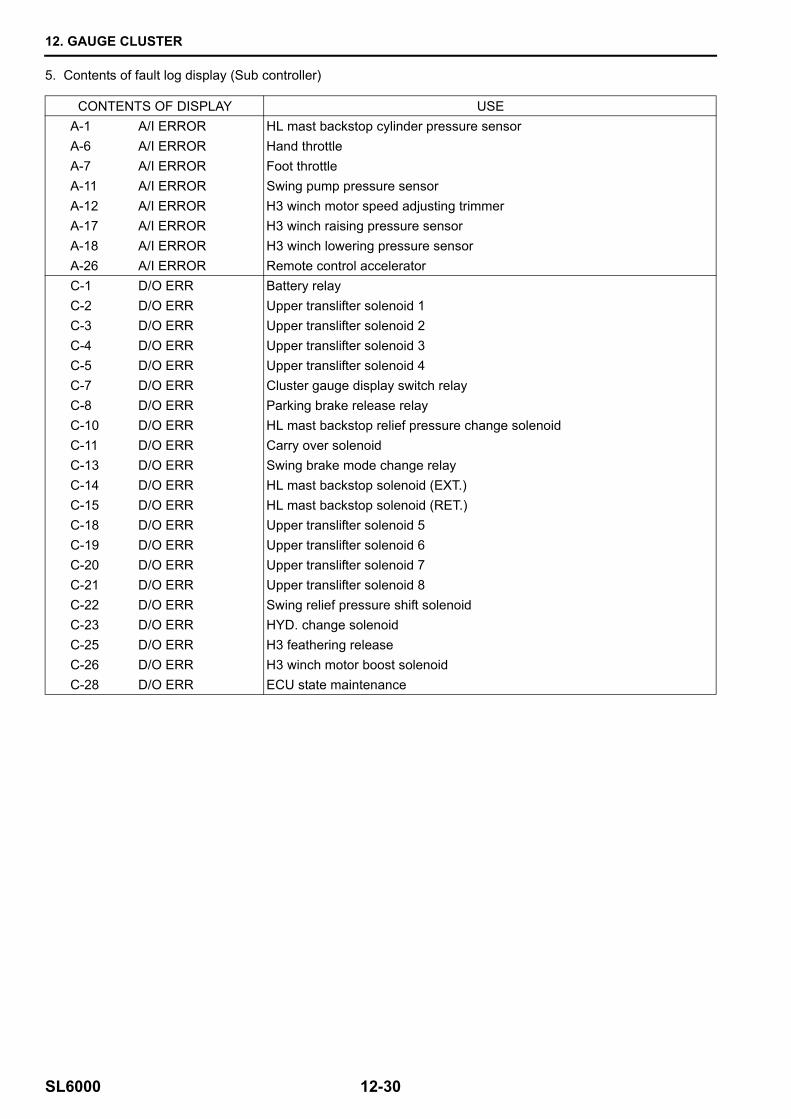
5. Contents of fault log display (Sub controller)
CONTENTS OF DISPLAY USEA-1 A/I ERROR HL mast backstop cylinder pressure sensorA-6 A/I ERROR Hand throttleA-7 A/I ERROR Foot throttleA-11 A/I ERROR Swing pump pressure sensorA-12 A/I ERROR H3 winch motor speed adjusting trimmerA-17 A/I ERROR H3 winch raising pressure sensorA-18 A/I ERROR H3 winch lowering pressure sensorA-26 A/I ERROR Remote control acceleratorC-1 D/O ERR Battery relayC-2 D/O ERR Upper translifter solenoid 1C-3 D/O ERR Upper translifter solenoid 2C-4 D/O ERR Upper translifter solenoid 3C-5 D/O ERR Upper translifter solenoid 4C-7 D/O ERR Cluster gauge display switch relayC-8 D/O ERR Parking brake release relayC-10 D/O ERR HL mast backstop relief pressure change solenoidC-11 D/O ERR Carry over solenoidC-13 D/O ERR Swing brake mode change relayC-14 D/O ERR HL mast backstop solenoid (EXT.)C-15 D/O ERR HL mast backstop solenoid (RET.)C-18 D/O ERR Upper translifter solenoid 5C-19 D/O ERR Upper translifter solenoid 6C-20 D/O ERR Upper translifter solenoid 7C-21 D/O ERR Upper translifter solenoid 8C-22 D/O ERR Swing relief pressure shift solenoidC-23 D/O ERR HYD. change solenoidC-25 D/O ERR H3 feathering releaseC-26 D/O ERR H3 winch motor boost solenoidC-28 D/O ERR ECU state maintenance
12. GAUGE CLUSTER
12-31 SL6000
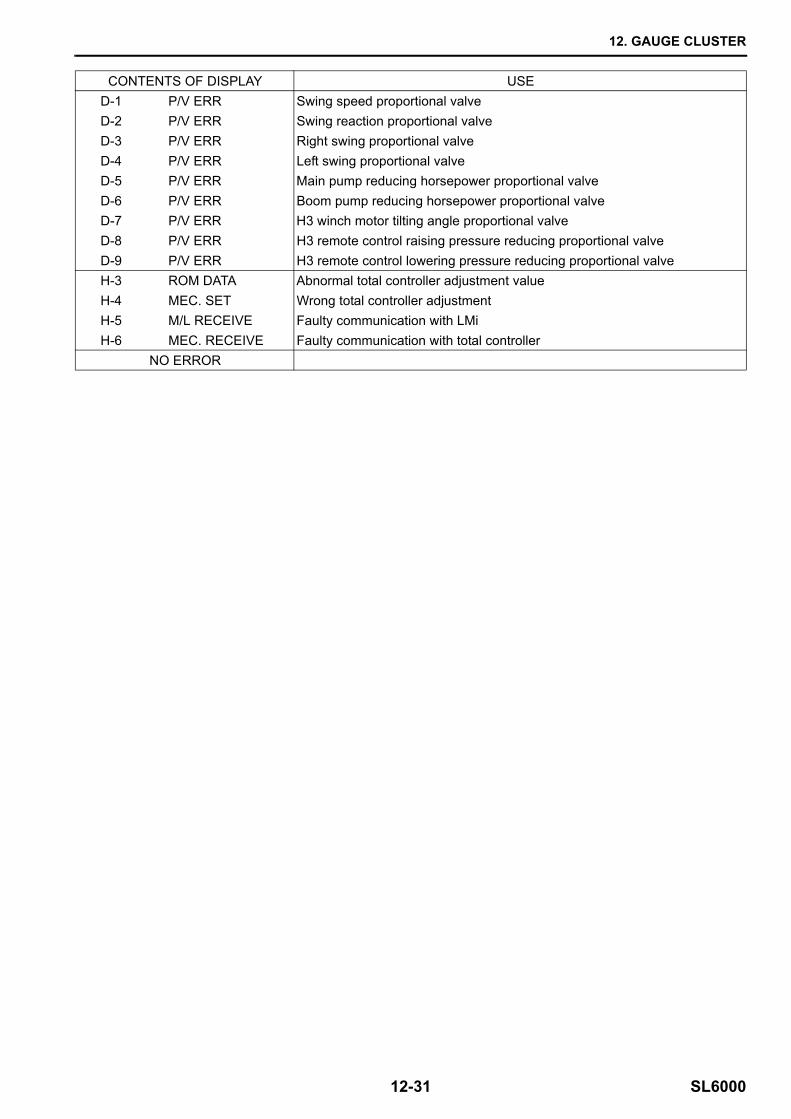
CONTENTS OF DISPLAY USED-1 P/V ERR Swing speed proportional valveD-2 P/V ERR Swing reaction proportional valveD-3 P/V ERR Right swing proportional valveD-4 P/V ERR Left swing proportional valveD-5 P/V ERR Main pump reducing horsepower proportional valveD-6 P/V ERR Boom pump reducing horsepower proportional valveD-7 P/V ERR H3 winch motor tilting angle proportional valveD-8 P/V ERR H3 remote control raising pressure reducing proportional valveD-9 P/V ERR H3 remote control lowering pressure reducing proportional valveH-3 ROM DATA Abnormal total controller adjustment valueH-4 MEC. SET Wrong total controller adjustmentH-5 M/L RECEIVE Faulty communication with LMiH-6 MEC. RECEIVE Faulty communication with total controller
NO ERROR
12. GAUGE CLUSTER
SL6000 12-32
Top Related