


Languages
Pages
Legal

Skinning Characters using Surface-Oriented Free-Form Deformations
Karan [email protected]
Evangelos [email protected]
Alias|wavefront210 King St. E., Toronto, Canada M5A 1J7
AbstractSkinning geometry effectively continues to be one of
the more challenging and time consuming aspects ofcharacter setup. While anatomic and physically basedapproaches to skinning have been investigated, manyskinned objects have no physical equivalents. Geomet-ric approaches, which are more general and provide finercontrol, are thus predominantly used in the animationindustry. Free-form deformations (FFD) are a power-ful paradigm for the manipulation of deformable objects.Skinning objects indirectly using an FFD lattice reducesthe geometric complexity that needs to be controlled bya skeleton. Many techniques have extended the origi-nal box-shaped FFD lattices to more general control lat-tice shapes and topologies, while preserving the notionof embedding objects within a lattice volume. This pa-per in contrast, proposes a surface-oriented FFD, wherethe space deformed by the control surface is defined bya distance function around the surface. Surface-orientedcontrol structures bear a strong visual semblance to thegeometry they deform and can be constructed from thedeformable geometry automatically. They also allow lo-calization of control lattice complexity and deformationdetail, making them ideally suited to the automated skin-ning of characters. This approach has been successfullyimplemented within theMaya2.0animation system.
Key words: Character animation, skinning, deformers,free-form deformations.
1 Introduction
A layered approach [1] to the modeling and animationof articulated figures is a widely adopted methodology.The layers may be broadly classified into skeletal, mus-cle, underlying tissue and skin. These layers are largelysymbolic of their contribution to the visual appearanceof the animated character, since physical equivalents ofbones or muscles for characters modeled from inanimateobjects such as a lamp, need not exist. Hair, clothes andaccessories form further layers on many characters. Lay-ers are often omitted, collapsed together, or further clas-sified depending on the sophistication of the application.
The skin is particularly important since it largely es-tablishes the visual appearance of a character. A num-ber of techniques for the modeling and animation of themuscleandskin layers have been investigated [1, 5, 10,11, 13, 16, 17, 18]. The typical workflow for setting upan articulated character involves building a model repre-senting the geometric skin of the character in some pose.An underlying skeletal structure comprising of referenceframes at joints is also constructed to control the move-ment of the articulations. More sophisticated methodolo-gies sometimes also model underlying bones and musclesusing geometry. The skinning algorithm is responsiblefor deforming the geometric skin to respond to the motionof the underlying skeleton. Skinning approaches can beclassified as geometric or physically based. While a num-ber of physical models for muscle and skin [4, 11, 16, 18]exist, techniques used in the animation industry continueto be predominantly geometric [1, 5], because of theirgenerality and control.
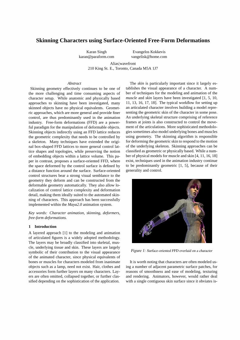
Figure 1: Surface-oriented FFD overlaid on a character
It is worth noting that characters are often modeled us-ing a number of adjacent parametric surface patches, forreasons of smoothness and ease of modeling, texturingand rendering. Animators, however, would rather dealwith a single contiguous skin surface since it obviates is-
sues of continuity between adjacent pieces of skin duringanimation. A geometric skinning approach that presentsa single skin interface for setup and animation is thus de-sirable. Subdivision surfaces provide the smoothness andparameterization characteristics of surface patches whilepresenting a single control mesh as an animation inter-face [5]. We aim to provide the animation interface andcontrol of a subdivision surface to an underlying skin ofarbitrary geometric representation.
A good skinning algorithm needs to provide an auto-mated attachment of points representing the skin surfaceof a character to an underlying skeletal and muscle struc-ture. Subsequently, it should be easy for an animator toedit the default attachments, as it is difficult to univer-sally predict how an arbitrarily shaped object is intendedto be controlled by its skeleton. Once pieces of skin areattached to corresponding pieces of muscle and bone, thestrength with which pieces of the skin are deformed byparts of the skeleton should be easy to control. The ef-fect on skin from changes in underlying layers, such asmuscle shape or bone position should be easy to over-lay. We avoid an explicit bone and muscle model sincethe range of articulated deformable objects and skin de-formation effects is as vast as the animator’s imagination.Instead we emphasize a system where any localized de-formation can be easily specified and controlled by un-derlying skeletal motion. The resulting skin deformationshould be smooth and predictable. Finally, the approachshould be efficient allowing real-time interactivity for atleast a low resolution model of the geometric skin. Em-pirical geometric approaches to skinning [1, 10, 13, 17]have shown realistic results at interactive rates.
A number of techniques have advanced the box-shapedlattices of the original FFD formulation [12], to allowfor greater generality in the shapes and topologies of thecontrol lattice. This is in accordance with the generaltrend for the control structures of higher level deforma-tion techniques to bear a visual correlation to the geome-try they deform [5, 14]. Most FFD approaches, however,preserve the notion of a volume enclosed by the controllattice, within which objects are embedded.
In contrast, we propose here a deformation techniquethat is surface-oriented. The region of space deformed bythe control point structure is not the volume enclosed bythe control points but is based on a distance metric froma surface defined by the control point structure. Surface-oriented deformation control structures provide a bettervisual representation of the geometry they deform andcan typically be constructed from the deformable geom-etry itself (See Figure 1). They allow better localizationof control lattice complexity and deformation detail as il-lustrated by the results in our implementation.
Our surface-oriented FFD thus aims to represent andcontrol any underlying object by a single control poly-mesh. Unlike subdivision surfaces the control polymeshdoes not have a limit surface that represents the object.Our goal instead is to allow the advantages of a singlecontrol mesh to represent and control an object that has analternate surface model (such as a set of surface patches,a different control mesh or even a subdivision surface).The control mesh can be used to both visually representthe surface model and to drive the deformation of the ob-ject. The control mesh can be user created or automat-ically synthesized from data, for example by tesselatingand stitching various surface patches that define the de-formed skin. In addition to their application in skinningcharacters, surface-oriented FFDs are a useful tool for themulti-resolution modeling and animation of objects.
The remainder of this paper is organized as fol-lows: Section 2 describes characteristics of existingfree-form deformation techniques and motivates thesurface-oriented free-form deformation approach. Sec-tion 3 presents the surface-oriented deformation algo-rithm. Section 4 provides an analysis of the propertiesof the algorithm and describes an extension of it. Sec-tion 5 describes the implementation of an automated skin-ning workflow based on surface-oriented free-form de-formations, within the modeling and animation systemMaya2.0. Section 6 concludes with a discussion of theresults obtained.
2 Free-form Deformation Techniques
In this section we present an overview of a number ofexisting free-form deformation techniques and contrasttheir properties with the characteristics of our surface-oriented deformation algorithm described in Section 3.
Free-form deformations (FFD) were originally intro-duced by Sederberg and Parry [12] as a general tech-nique where objects are deformed by warping a volumeof space within which the objects are embedded. The vol-ume of space is typically defined using a structure con-necting a set of control points. Spatial deformations arethen accomplished by the manipulation of these controlpoints. A one-to-one correspondence is established be-tween points within the original and deformed volumesof space. Objects embedded within the original volumeare thus deformed by mapping the point-set representingthe object to their corresponding points in the deformedvolume. This process typically involves calculating a pa-rameterization of the volume based on the topology of itscontrol point structure. The actual mapping of an unde-formed point to a point in the deformed volume is then afunction of the deformed positions of the control pointsfor the given parameterization. Continuity of the corre-

spondence function is crucial to the smoothness proper-ties of the deformed object.
Sederberg and Parry [12] used a parallelopiped latticeof control points to define a trivariate Bezier volume. Themapping of points within the parallelopiped volume toa trivariate basis is straightforward. Evaluating the de-formed point is simply a matter of evaluating the Bezierequation for the deformed set of control points. Griess-mair and Purgathofer [6] extended this technique to em-ploy a trivariate B-spline basis. While these methods aresimple, efficient and in popular use they suffer from thedrawback of a restrictive original volume shape. Paral-lelopiped volumes rarely bear any visual correlation tothe objects they deform and typically have a globally uni-form lattice point structure that is larger than is requiredfor the deformations to which they are applied.
Coquillart [3] extended the box-shaped lattices to al-low for a richer set of shapes (EFFD), constructed by joinoperations applied to paralleloped lattices. The parame-terization of a point within the original trivariate volumeis calculated numerically, making the technique less sta-ble than the original FFD [12] in the general case.
Chang and Rockwood [2] present an approach where adeCasteljau approach of repeated affine transformationsdefines the deformable space around a Bezier curve. Theapproach is intuitive and fast but restricted in the rangeand local control of the deformations it can capture.
MacCracken and Joy [7] use a volume equivalent of theCatmull-Clark subdivision scheme for surfaces to itera-tively define a volume of space based on a control pointstructure of arbitrary topology. This is a significant stepin increasing the admissible set of control lattice shapes.The technique is powerful and its only real shortcom-ing are the potential continuity problems of the mappingfunction (a combination of subdivision and interpolation)of points within the volume. The approach also suffersfrom the same discontinuity problems as Catmull-Clarksurfaces at extraordinary vertices.
Dirichlet free-form deformations [9] is an approachbased on the Voronoi structure defined within the convexhull of a set of points. While there is no restriction onthe shape of the volume, the deformations are controlledsolely by the parameterization defined by natural neigh-bour interpolants. These interpolating functions have sin-gularities that result in unwanted deformation artifacts.
All the above approaches are strongly volume-oriented. The structure of the control points explicitlydefines a volume of deformable space. The deformationfunctionD(P ) for a pointP can be typically representedbyD(P ) =
∑ni=1Wi(P )Pi, wherePi is a control point
andWi a function that maps a pointP to a weight valuefor the control pointPi. For FFDsWi(P ) = Bi(s, t, u),
whereB is the Bezier basis function ands, t, u the pa-rameterization ofP within the parallelopiped volume.
The property that affine transformations to the controllattice are transmitted as such to the deformed points isdesirable. Suppose an affine transformationM were ap-plied to the lattice.D(P ) = PM =
∑ni=1Wi(P )(PiM)
or P =∑ni=1Wi(P )Pi, wherePi are the positions
of the control points in the original lattice. Thus foraffine transformations to be captured by the deforma-tion, the weighted average of control points for any pointin space point should be the point itself. Additionally∑ni=1Wi(P ) = 1 for the convex hull property of the de-
formation to hold. These properties can be verified forthe approaches described thus far.
Singh and Fiume [14] provided a different direc-tion to free-form deformations by making them surface-oriented, in that there was no explicit mapping of pointsbetween two deformable volumes. Instead points in spacewere associated with surface elements, parametric curvescalled wires. Transformation of these associated surfaceelements result in a deformation of space surroundingthe surface element. The control structure of a surface-oriented deformer typically bears a strong visual corre-lation to the object it deforms. Local control over thedeformation is easier and the arbitrary nature of the con-trol point structure makes it possible to introduce detaillocally without a global change to the object. At thesame time it is harder to ensure continuity properties andperfectly transmitted affine transformations for surface-oriented deformations. This paper addresses these issuesfor a polygon based deformer.
3 Surface-oriented deformations
The surface-oriented deformation algorithm described inthis paper, binds the surfaceS of a deformable object toa deformer objectO. Manipulation ofO is then trackedby S. Formally, we define the deformerO as a triple〈D,R, local〉 whereD andR are surfaces, referred to asthedriver surfaceandreference surfaceandlocal a scalarvalue.R is a congruent copy of the deformer surfaceD,that is made when surfaceS is bound toO. Subsequentmanipulation ofD causes a deviation relative toR thatdrives the deformation of surfaceS. The parameterlocalprovides control over the locality of the deformation.
For the purpose of our algorithm we need to be able tocompute localized orientation and scaling information atpoints on the surfacesD andR. We also require a uniqueand intuitive correspondence between points onD andR.This section treatsD andR to be polygon based surfacesof matching topology, for which these calculations arestraightforward and efficient.

3.1 Overview of the AlgorithmThere are three phases to the deformation process: Thebind phase, the registration phase and the deformationphase. The bind phase takes place once whereas the reg-istration and deformation phases are repeated as needed.During the bind phase, the user-specified deformer sur-face becomes the driver surfaceD. An identical copy ofit becomes the reference surfaceR, which along with auser-specifiedlocal value define the deformer objectO.
Let the driverD, and reference surfaceR of a deformerobject be represented by a collection of enumeratedcon-trol elements. These control elements are the triangularfacets of polygon based surfacesD andR (non-triangularfaces ofD are triangulated before the creation ofR dur-ing the bind phase). There is thus a simple bijective cor-respondence between the control elements ofD andRbased on element index.
The registration phase computes how much each con-trol element of the deformer object affects the deforma-tion of each pointP representing the surfaceS. Thisscalar value, referred to as theinfluence weightof thecontrol element forP , is calculated using a distance met-ric. Control elements closer toP have a higher influ-ence weight, and therefore affect the deformation ofPmore than elements further away fromP . The registra-tion phase typically takes place once, right after the bindphase and needs to be repeated only if the position of thereference surfaceR changes relative to the surfaceS.
The deformation phase follows the registration and isrepeated every time the deformer object’s driver surfaceD is manipulated. The influence weights calculated inthe registration phase as well as the spatial difference be-tween the control elements of the reference and driversurfaces are used to determine the deformation of eachpointP on the surfaceS.
The registration and deformation phases are now de-scribed in greater detail.
3.2 RegistrationDuring the registration phase, the influence weights forall the control elements and pointsP of the deformablesurfaceS are computed. Typically, the surfaceS is repre-sented by the set of pointsPS that are necessary to con-struct or approximateS. PS could therefore be a set ofvertices in a polygonal mesh, a set of control vertices ina free form surface or an unstructured set of points inspace. The deformation is applied to pointsP of thisset. Of the two surfaces of the deformer objectO, onlythe reference surfaceR is used in this phase. In our im-plementation, a distance metric represented as a scalarfunction f(d, local), is employed to compute the influ-ence weights. The first parameter,d, is the distance ofPfrom the control element. The second parameter,local,
controls the rate at which the functionf decays in valuewith an increase in distanced. We define the functionf(d, local) for anyd, local ≥ 0 to be:
f(d, local) =1
1 + dlocal. (1)
We define the distance of pointP from a triangularfacet to be the length of the vector
−−→PP ′ whereP ′ is the
point on the surface of the facet that is the closest topoint P . For each pointP and each control elementkof the deformer object’s reference surfaceR we definethe corresponding weightwPk = f(dPk , local), wheredPkis the distance of pointP from control elementk. Theinfluence weights for a pointP are normalized to pre-serve the convex hull property described in Section 2.The normalized weight vector for pointP is defined asUP = {uP1 , uP2 , . . . , uPn }, wheren is the number of con-trol elements of the influence object’s surfaces anduPkis the normalized weight of control elementk for point
P defined asuPk = wPk∑n
1wPk
. Section 5 will show that in
practiceuPk is set to zero for all but a few control elementsmaking the approach quite efficient.
The control elements as used for this algorithm definenot only a local position in space but also a local coordi-nate frame with axes−→e1 ,−→e2 ,−→e3 . In other words, each con-trol element defines its own coordinate system that can berepresented compactly with a4×4 transformation matrixQ. We denote transformation matrices of elements on thedriver and reference surface asQD andQR respectively.
Figure 2: The coordinate system of a polymesh face.
The position vector and the attached coordinate systemof a control element corresponding to a triangular facet ofa polygonal surface are derived directly from the verticesand edges of the facet (See Figure 2). An arbitrary order-ing may be assigned to the three vertices of the triangularfacet. Referring to these three vertices as verticesA, BandC we define the coordinate system for the control

element with its origin atA and axes as :
−→e1 = −→B −−→A,−→e2 = −→C −−→A,−→e3 =−→e 1 ×−→e 2
||−→e 1 ×−→e 2||. (2)
In addition to the influence weights, the registrationphase computes a representation of undeformed pointsP of surfaceS in the coordinate system defined by eachcontrol elementk of the reference surfaceR. This opera-tion can be easily carried out by inverting the transforma-tion matrix QRk of the control element.PRk = P (QRk )−1,wherePRk is the representation of the pointP in the localcoordinate system of control elementk of the referencesurfaceR.
During the deformation phase the pointP is deformedto preserve its local position,PRk , in the coordinate frameof the control elementk of the driver surfaceD.
3.3 DeformationThe deformation procedure maps each pointP in the setof pointsPS defining the undeformed surfaceS to a pointPdef . The setPSdef of all pointsPdef defines the de-formed object surface.
As the user manipulates the driver surfaceD of the de-former object, control elements onD change shape, po-sition and orientation. Comparing the coordinate systemdefined by the elementk on the reference surface and theelementk on the driver surface makes it possible to cal-culate the deformation effect of elementk on a pointP .The effect of each control elementk is weighted by thecorresponding normalized weight factoruPk and is addedto the contributions of all the other control elements.
During the registration phase, the representation ofpointP in the local coordinate system of the control ele-mentk on reference surfaceR was calculated to bePRk .In the deformation phase, we deform the point to have thesame local representation in the coordinate system of thecorresponding driver surface control element. The worldspace position of the pointP as deformed by control el-ementk is thus,P defk = PRk QDk , where QDk is the trans-formation matrix corresponding to the local coordinatesystem of the control elementk of the driver surface. Theeffect on pointP of each control element is weighted bythe corresponding normalized weight value stored in vec-tor UP . The weighted effects are added to compute theresulting pointPdef on the deformed surface:
Pdef =n∑k=1
uPk Pdefk . (3)
The algorithm can be adapted to allow parametric sur-face patches to represent the driver and reference surfaceby specifying control elements as a parametric samplingof points. The sampling density is a trade-off between
computational efficiency and the fidelity with which thesurface is represented. Sampling at knot vector param-eter values provides good local control on manipulationof the control vertices of the driver surface. The localcoordinate system in Equation 2 at a sample pointG, isdefined as−→e1 = −→tu ,−→e2 = −→tv ,−→e3 = −→n , where−→tu and−→tvare the tangents atG along two parameter curves, and−→nis the surface normal atG.
4 Algorithm Analysis
The algorithm imposes no restriction on the topologyof the deformer object or its position relative to the de-formable surfaceS. There are, however, implicit assump-tions that greatly influence the quality and control that thedeformer object has over the resulting deformation.
For a control element to provide good local control ofthe deformation of a region of the surfaceS, its spatialposition on the reference surfaceR should be closer tothe surfaceS than other control elements ofR.
Also for the deformation of the region of surfaceS toappear intuitive it should be proximal to the control ele-ment in absolute terms. Non-intuitive behavior may beobserved for points whose projection onto the plane ofthe triangle does not lie within the triangle. A pointPon the deformed surface can be visualised as being an-chored to its projection pointP projk on the plane of thetrianglek offset at a fixed distance, normal to the plane.The deformation ofP thus has a clear visual correlationto the deformation of the triangle if and only ifP projk lieswithin this triangle.
These observations place an implicit assumption on thenature ofR relative toS, in that every pointP of S shouldbe proximal to some trianglek of R and have its projec-tion onto the plane of trianglek lie within it. This is in ac-cordance with the motivation for our deformer to providea lower resolution visual model of our original surfaceS.
4.1 Algorithm Properties• The surfaceS does not deform upon being bound to
a deformer object. Since the driver and the referencesurfaces of the deformer object are spatially identi-cal when bound,Pdef = P defk = P for all controlelementsk.
• The deformation of space defined by the algorithm iscontinuous and intuitive. The parameterlocal pro-vides good control over the localization of deforma-tion effects.
• Rotations and translations applied to the entiredriver surface are imparted precisely to the surfaceS, since the weight values used in equation 3 arenormalized.

• Warping of space normal to the plane of the con-trol elements is captured as a constant offset fromthe control element, since−→e3 is a normalized vector,normal to the plane of the triangle in bothR andD.
4.2 Extending the AlgorithmWe now look at shortcomings of the approach describedthus far. The first deals with non-intuitive deformationsresulting from a pointP being anchored to its projectionP projk on the plane of a trianglek of the reference sur-face, whereP projk does not lie within the triangle. It isconceivable to clampP projk to the closest point on the tri-angle boundaryP closek and calculate the deformed pointas two offsets from the point corresponding toP closek onthe driver surface. The first offset isP projk −P closek in theplane of the triangle and the second,P −P projk normal tothe plane of the triangle. While this addresses the short-coming, the change introduces a first order discontinuityof deformation asP projk for pointsP transitions acrossthe triangle boundary.
The second shortcoming deals with the fact that the al-gorithm does not capture the warping of space in a direc-tion normal to the plane of its control elements. Uniformscaling of the driver surfaceD, for example will scale theobject precisely in the plane of the control elements ofD, but maintain a constant distance from the elements ina direction perpendicular to them.
Both of these shortcomings can be attributed to the am-biguities in the perception of the behavior of space aroundthe deformer object on manipulation of the driver surface.There are infinitely many ways by which a user can de-form space such that the discrete set of points of a driversurface are manipulated to the same position. In eachcase, however, the behavior of the spatial neighbourhoodof the points of the driver surface is different.
This ambiguity can be reduced by defining a coordi-nate system by introducing three additional points for ev-ery given point on the deformer surface. These pointsform mutually independent axes with the point on the de-former surface as the origin. The three points are subse-quently subjected to the same manipulation function asthe corresponding point on the deformer surface. Whilethis coordinate system represents the space of a locallinear transformation accurately, non-linear deformationsare once again only approximated. This gives us some in-sight into the nature of spatial deformations and solutionsto them by providing the user with additional control.
Every trianglek in our extended model has three localcoordinate systems instead of one, centered at each ver-tex of the triangle and constructed during the bind phase.We register the pointP by computing the local positionof the point within each of the three coordinate system as
described in Section 3.2. We also generate a deformedpoint with respect to each of the three coordinate sys-tems of trianglek. The three deformed points are thenweight averaged to a single resultantP defk . The weightsin this case are provided by the barycentric coordinatesof P closek (the closest point toP from trianglek). Thedeformed result of the various control elements are com-bined as in Section 3 to determine the final position of apoint. It is straightforward to see that the range of defor-mation behavior captured above encompasses that of thethe algorithm in Section 3.
5 Skinning Workflow
It is a fairly common practice in the animation industryto model articulated figures using a number of surfacepatches. Joint regions such as the shoulder in Figure 3are particularly problematic to skin. This is because therange and degrees of freedom of the joint cause large vari-ations in the motion of points. It is also the case that of-ten a number of patches converge in the region arounda joint, making the problem of skinning the geometrywhile maintaining smoothness and continuity across thepatches a formidable task.
Figure 3: Shirt skinned using surface-oriented FFDs
A single surface-oriented deformer can abstract thisunderlying patch complexity so the user has to deal withthe more tractable problem of skinning a single lower res-olution object that bears a close visual semblance to theactual geometry. We prescribe a simple workflow thatlargely automates the entire skinning process. The shirtin Figure 3 was skinned with such a deformer.
The basic skinning workflow involves the constructionof a single surface-oriented deformer around a character.This deformer is essentially a low-resolution representa-tion of the character (See Figure 1). More importantlythe resolution is adaptive, to allow a greater resolution ofcontrol points in the region of character joints.

Figure 4: Skinning workflow: polyhedral deformerbound to skeleton(left), deformed surface (right)
Geometric representations such as parametric surfacepatches and implicit functions have well established tes-selation algorithms. Polymesh decimation algorithmshave also been well studied [8, 15]. For the commoncase where the underlying geometric skin comprises ofa number of surface patches, the patches are tesselatedindependently and then stitched together to form a singledeformer object. The stitched mesh represents all or alarge section of the skin of an articulated character. Theunderlying geometry is bound to and controlled by thedeformer object using the algorithm described in Section3. The deformer object is bound to the underlying skele-ton using any number of techniques [1, 14, 18]. We findthat in practice it is often worthwhile to define the motionof individual points by keyposing them against variousjoint angle positions. The reduced point complexity ofthe deformer object makes this a reasonable task that al-lows complete customizability to be layered over the ba-sic motion of the points of the deformer object as dictatedby the basic binding technique used (See Figure 4). Finerlocal control may also be achieved at any point of time bysubdividing triangles in a problematic region to generatea larger number of control elements. Non-triangular de-former polymeshes are internally triangulated, so as notto subject a user to unnecessary visual clutter.
A common problem with techniques that use Eu-clidean distance to determine correspondence betweenthe deformed and deformer object, is that quite often re-gions of the deformer object will strongly influence re-gions of the deformable surface which happen to be spa-tially proximal but are quite distinct in the eyes of theuser. A clear example of this can be seen in Figure 5where the deformer region of the right thigh pulls on partof the left thigh geometry even though it should not affect
it at all. Our implementation, therefore constructs, foreach pointP , a subset of contributing control elementsCP , from the set of control elements of the deformer ob-ject for a given point. As can be seen from Equation 1 thefunctionf rapidly decays in value with distance such thatthe normalized influence weights are likely to be signifi-cantly larger than zero for only a small number of controlelements. By default the control elements with a signif-icant non-zero influence defineCP . The set, however, isunder user control and may be edited if necessary. Thusby removing the control elements of the right thigh fromthe contributing control element sets for points of the leftleg we can get the desired behavior.
Figure 5: Deformation using a surface-oriented FFD
The algorithm described in this paper has been imple-mented as a general deformation technique within ourmodeling and animation systemMaya2.0. The skinningof geometry has been automated as summarized below.
1. Polygonize surface patches or other geometric rep-resentation of objects to be skinned. Decimate andweld polygon objects as required to generate a fewlow resolution deformer objects.
2. Bind the deformer driver surface points to the skele-ton. Points are rigidly attached to the Euclideanclosest limb by default.
3. The control points of the deformer can be then key-posed against various skeletal and muscle attributesto generate custom skinning behavior.
4. The various parameters of the surface-oriented free-form deformation and the contributing element setsfor various points may also be edited.

6 Results and Conclusion
We find in practice that surface-oriented free-form defor-mations address many requirements of geometric skin-ning. The deformer object itself provides a reasonably ac-curate low resolution representation of the skinned geom-etry, making it perfectly suitable as a stand-in for highlyinteractive animation tasks. The process is largely auto-mated and may be all an animator needs for a quick setup.More importantly, however, the animator still has controlat the finest level, through increasing degrees of detail.An analysis of the algorithms in Section 3 and 4, showthem to be robust, efficient and of predictable deforma-tion behavior and continuity. This is corroborated by thepractical results shown in this paper and on a few of thecharacters of the animation short Bingo.
Our implementation combines multiple deformers onan object as described by Singh and Fiume [14]. Surface-oriented FFDs have also been used as a compelling mod-eling and animation tool with much of the appeal andcontrol of a subdivision surface. Figure 6 shows the phys-ical simulation of a polymesh deformer draping over atable top controlling a NURBS surface rendered with achecker texture.
Figure 6: Physical simulation of a polyhedral mesh con-trolling a superposed NURBS tablecloth
While the extended algorithm in Section 4 gives usgreater control and the property that all affine transforma-tions to the deformer object are imparted perfectly to theunderlying geometry, we find the algorithm of Section 3to be simpler for an animator to understand and sufficientfor the skinning application discussed in this paper.
Acknowledgements
We thank Barbara Balents and theMaya team for theirhelp in the design and implementation of this techniqueand Paul Thuriot for providing us with invaluable casestudies of character setup using surface-oriented FFDs.
References
[1] J. Chadwick, D. Haumann and R. Parent. Lay-ered construction for deformable animated charac-ters.Computer Graphics, 23(3):234–243, 1989.
[2] Y.K. Chang and A.P. Rockwood. A generalizedde Casteljau approach to 3D free-form deformation.Computer Graphics, 28(4):257–260, 1994.
[3] S. Coquillart. Extended free-form deformations: Asculpting tool for 3D geometric modeling.ComputerGraphics, 24(4):187–196, 1990.
[4] D. Chen and D. Zeltzer. Pump it up: Computer ani-mation of a biomechanically based model of muscleusing the finite element method.Computer Graphics,26:89–98, 1992.
[5] T. DeRose, M. Kass and T. Truong. Subdivision sur-face for character animation.Computer Graphics,85–94, 1998.
[6] J. Griessmair and W. Purgathofer. Deformation ofsolids with trivariate B-splines. Eurographics 89,137–148.
[7] R. MacCracken and K. Joy. Free-form deformationswith lattices of arbitrary topology.Computer Graph-ics, 181–189, 1996.
[8] A. Lee, W. Sweldens, P. Schroder, L. Cowsarand D. Dobkin. MAPS: Multiresolution adaptiveparametrization of surfaces.Computer Graphics, 95–105, 1998.
[9] L. Moccozet and N. Magnenat Thalmann. Dirichletfree-form deformations and their application to handsimulation.Computer Animation, 93–102, 1997.
[10] N. Magnetat-Thalmann, D. Thalmann. Humanbody deformations using Joint Dependent Local Op-erators and Finite Element Theory.Making ThemMove, Morgan Kaufmann, 243–262.
[11] F. Scheepers and R. Parent and W. Carlson and S.May Anatomy-Based Modeling of the Human Mus-culature.Computer Graphics, 163–172, 1997.
[12] T. Sederberg and S. Parry. Free-form deforma-tion of solid geometric models.Computer Graphics,20:151–160, 1986.
[13] K. Singh, J. Ohya and R. Parent. Human figure syn-thesis and animation for virtual space teleconferenc-ing. IEEE VRAIS, 118–126, 1995.
[14] K. Singh and E. Fiume Wires: A geometric de-formation technique.Computer Graphics, 405–414,1998.
[15] G. Taubin, A. Gueziec, W. Horn and F. Lazarus Pro-gressive forest split compression.Computer Graph-ics, 123–133, 1998.
[16] Y. Lee, D. Terzopoulos and K. Waters. Realisticmodeling for facial animation.Computer Graphics,55–62, 1995.
[17] M. Walter and A. Fournier. Growing and animatingpolygonal models of animals.Eurographics, 151–158, 1997.
[18] J. Wilhelms and A. Van Gelder. AnatomicallyBased Modeling. Computer Graphics, 173–180,1997.