


Languages
Pages
Legal


DE2HS
COMPACT “TRUE” TWO HAND “NON TIE DOWN” SAFETY CONTROLS
3
SUB-BASE MOUNTEDSOLENOID VALVES FORQUICK REPLACEMENT WITHOUTDISTURBING ORIGINAL PIPING
RAM LOCKDOWN VALVE
Series ‘N‘
Hydro Pneumatic Press Cylinder
Series ‘A‘

Q (NL)AIR. CONSU. @ 5 BARS
@ 5 BARS
HYDRO PNEUMATIC PRESS DIMENSIONS
622722
808080
6.17.5
4
Output Forces (Kgf.) at Inlet Air Pressure of 5 Bars.
Tonnage AH21/24 A026 A046
Approach
Power
Return
90
2495
140
120 140
1970 3900
210 290
A016
90
140
975
A081/084
140
7750
290
A041/044
120
4000
210
2.52.5
2.52.5
2.52.52.5
Example :- A 4Tonne,50mm stroke with 6mm power stroke press is used at 5 bars to cut Aluminium ‘washer from a sheet of 10 pieces per minute.1) From above chart model A41-50 cylinder consumes 6.7 NL of air per cycle2) @ 10 strokes/min air consumption = 6.7 X 10 = 67.0 NLPM3) Electric Power Used = 67.0 120 =0.56 HP 0.42 KW4) Cost of electricity @ Rs 10.0 per KWH =0.42 X 10 = Rs 4.205) Cost of electricity per cut piece = 4.20 10 60 = 0.007 Rs i.e 0.70 paisa per piece
15T 30T
435
29175
1160
680
44950
1300
AH 21-50AH 21-75AH 21-100AH 21-150AH 24-75AH 24-100AH 24-150
495545595695641691791628678778
712
708808713763863
97979797104104104757575128128128128444444636363154154154154
4.14.85.57.06.97.69.010.111.213.56.67.7
8.911.211.112.314.618.119.823.211.413.214.918.319.621.3
24.8
14750
825
435
45T

6
C2
C2
190
180
217
166
175
190

Plain Anti Rotation Guide Guided Moving Platen
N Series
A Series
N Series
A SeriesN Series
A Series
5

7

8
Compact ‘C’ Frame Presses
Shaft Straightening Press Manually Operated Press Hexagonal Marking Machine
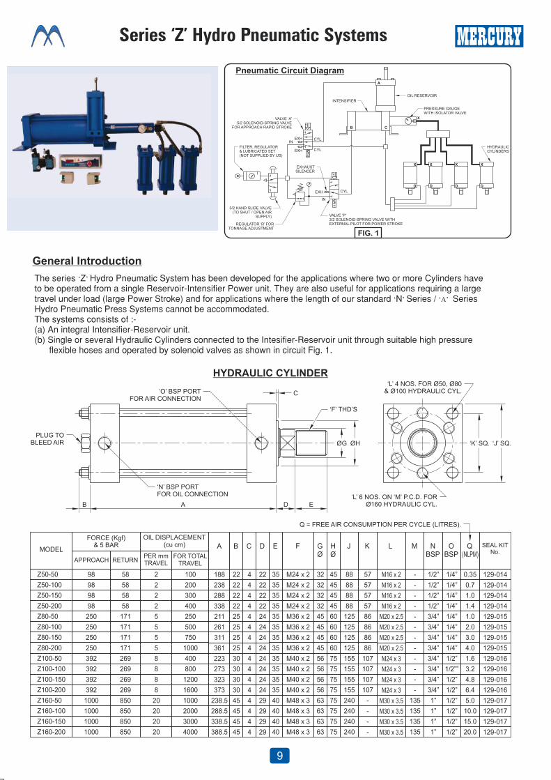
The series ‘Z’ Hydro Pneumatic System has been developed for the applications where two or more Cylinders haveto be operated from a single Reservoir-Intensifier Power unit. They are also useful for applications requiring a largetravel under load (large Power Stroke) and for applications where the length of our standard ‘N’ Series / ‘A’ Series Hydro Pneumatic Press Systems cannot be accommodated.The systems consists of :-(a) An integral Intensifier-Reservoir unit.(b) Single or several Hydraulic Cylinders connected to the Intesifier-Reservoir unit through suitable high pressure flexible hoses and operated by solenoid valves as shown in circuit Fig. 1.
9

10
12.5
12.5
3.8
3.8
12.5
12.5
3.8
3.8
15.3
15.3

Mercury Website About Us All Products Contact Us
1 Jaipur 1 Kochi 1 Kolhapur 1 Kolkata 1 Mumbai 1 Nasik 1 New Delhi 1 Lucknow 1 Pune
1 Ahmedabad 1 Aurangabad 1 Bangalore 1 Chandigarh 1 Chennai 1 Coimbatore 1 Hyderabad 1 Indore
Lucknow
Top Related