
![Ø 0.2 Dumet Wire Glass bead...Ø 0.2 Dumet Wire Glass bead 3 max UNITS: [mm] TEWA TEMPERATURE SENSORS HIGH PRECISION NTC THERMISTORS AND TEMPERATURE SENSORS Tewa Temperature Sensors](https://static.fdocuments.in/doc/165x107/60aaa6b97178df7b551a322a/-02-dumet-wire-glass-bead-02-dumet-wire-glass-bead-3-max-units-mm.jpg)


Languages
Pages
Legal


ii
Simulation of 1-Wire Sensors
SALWAN NAJAR
Master of Science Thesis in Medical Engineering
Stockholm 2012

ii
iii
This master thesis project was performed in collaboration with
Karolinska University Hospital.
Supervisors at Karolinska University Hospital: Daniel Blom and Pierre
Foglöv, in Medical Technology department (MT).
Simulation of 1-Wire Sensors
Simulering av 1-Wire sensorer
SALWAN NAJAR
Master of Science Thesis in Medical Engineering.
Advanced level (Second cycle), 30credits.
Supervisor at KTH: Stefan Karnebäck.
Examiner: Kaj Lindecrantz
School of Technology and Health
TRITA-STH. EX 2011:21
Royal Institute of Technology
KTH STH
SE-141 86 Flemingsberg, Sweden
http://www.kth.se/sth

iv

Royal Institute of Technology Simulation of 1-Wire Sensors
Master Degree of Medical Engineering
v
Acknowledgements
This thesis was written by the order of Karolinska University Hospital in Stockholm, an
institution well- known around the word for its active engagement in improving health
services. The realization of this thesis would not have been possible without the support
from some people and for this reason I would like to thank all of them.
I want especially to thank my supervisor Stefan Karnebäck at the school of Technology
and Health, Royal Institute of Technology STH, who was a great supporter through this
project. Also I want to thank my supervisors Daniel Blom, Pierre Foglöv and the
programmer Roger Blom in the Medical Technology department (MT) at Karolinska
University Hospital, who all answered my questions, queries and wonders with the
utmost integrity.
Last but not least I would like to thank my family and friends for their support and help.
Salwan Najar
Stockholm, 1st May, 2012

vi

Royal Institute of Technology Simulation of 1-Wire Sensors
Master Degree of Medical Engineering
vii
Abstract
The 1-wire bus is a communication bus system which is designed to provide data,
signals and power over a single signal with low data rates, a high resolution and a long
range. It is typically used to communicate with small inexpensive devices, as
temperature sensors, which is worked as a slave with the master computer (PC).
The 1-wire bus system provides the sufficient control and operation signal, a unique ID
serial number of each sensor and it supports multiple temperature sensors by a driving
power (Parasite Power) on single line.
On the 1-Wire bus system, temperature sensors are supplied by two types of power
supplies, external Power supply and Parasitic Power.
The aim of this project is to program the microprocessor (Arduino) by using Arduino
programming language to work as a temperature sensor type DS18B20 and also as a
slave on the 1-Wire bus system.
This report explains the 1-Wire bus system techniques and how the communication is
achieved between the master and the slave (sensors) to measure the temperature values.
The measured temperature values are collected from the output of each active sensor on
the 1-Wire bus. These data are displayed by the personal computer (PC) which is
worked as a master on the 1-Wire bus, and the data are represent the measured
temperature values from twelve active sensors on the bus system.
In this thesis, the temperature values from the 12 active sensors can be read and
displayed on the master (PC) by using the following programs: Open Logger One Wire
(OLOW) program, One Wire Viewer, DigiTemp and OWFS and I validated all the
temperature values from these active sensors which are read and monitored by the drive
bus programs. The comparison is done among the measured temperature values to see if
the active sensors are given accurate temperature values with different drive bus
programs.
The project shows that the sensors can be connected in a network with the master, by
using 1-Wire bus techniques. This thesis will be used by Karolinska University
Hospital, and it can also be developed for different requirements in the future.
Keywords: 1-wire bus, Parasite Power, External Power Supply, Sensor, Arduino.

viii

Royal Institute of Technology Simulation of 1-Wire Sensors
Master Degree of Medical Engineering
ix
Table of Contents
1. INTRODUCTION ......................................................................................................................1
1.1 Background ...................................................................................................................... 1
1.2 Assignment ...................................................................................................................... 1
1.3 Purpose ............................................................................................................................ 2
1.4 Method .............................................................................................................................. 2
2. 1-WIRE BUS SYSTEM ............................................................................................................3
3. MICROPROCESSOR (Arduino) .............................................................................................4
4. THE PERFORMANCE OF SIMULATION AND THE VALIDATION OF MEASURED
TEMPERATURE VALUES... .................................................................................................. 5
4.1 Logic Program ...................................................................................................................5
4.2 Open Logger One Wire Program (OLOW) ...................................................................6
4.3 Open Logger ....................................................................................................................7
4.4 One Wire Viewer ..............................................................................................................9
4.5 DigiTemp …………………………………………………………………………………………………………….…...10
4.6 OWFS ……………………………………………………………………….…………………….………………………..12
4.6.1 Owserver….......................................................................................................12
4.6.2 Owhttp.…..........................................................................................................13
5. EXPLANATION THE CONNECTION AND THE SIMULATION of ARDUINO ON THE
1-WIRE BUS SYSTEM ……….……………………….………………………………………………………………......14
6. RESULTS ................................................................................................................................ 36
7. CONCLUSIONS ..................................................................................................................... 37
REFERENCES ............................................................................................................................ 39
APPENDICES ............................................................................................................................. 40
Appendix A. The Hard Code Program of Arduino................................................................. 41
Appendix B. Graphics the Measured Temperature Values by Four Different Drive Bus
Programs ……………………….………………………………………………………………….………………65

x

Royal Institute of Technology Simulation of 1-Wire Sensors
Master Degree of Medical Engineering
1
1. INTRODUCTION
1.1 Background
This thesis has been completed in the Medical Technology department (MT) at
Karolinska University Hospital within the field of medical technology, commissioned by
Daniel Blom (supervisor in Medical Technology department (MT)) and Stefan
Karnebäck, (lecturer at school of Technology and Health, KTH-STH). The experiments
upon which this thesis (30 credits) is based were intended to simulate temperature sensors
(DS18B20) on the 1- Wire bus system. This thesis will be used at Karolinska University
Hospital because they use temperature sensors in many places (e.g.: refrigerators,
freezers, oven, incubators, cold rooms, etc.), all of which are controlled by 1- Wire
technology.
In this project, I have chosen the microprocessor (Arduino) and it is simulated to be a
slave and to work as a temperature sensor type (DS18B20) and this microprocessor is
connected with the master by using 1-Wire bus technology. The precondition for a
reliable 1-Wire operation is a correct match among network components (i.e., master,
network cabling, and Wire slave devices, "slaves"), and the satisfactory performance of
the 1-Wire cannot always be expected when the bus masters are improperly designed or
implemented, or when masters intended for short line use are passed into service with
greatly extended communications lines.
1.2 Assignment
The aim of this project is to find the solutions of the different tasks which lead to the best
results. The main topic is to find out how the protocol, the procedures of the
microprocessor, and its hard code are made to work as a slave on the 1- Wire bus system
and as 12 temperature sensors, which are called DS18B20, with best performance. This
can be done by using the PC computer as a master with different drive bus programs as
an Open Logger program, One Wire Viewer, DigiTemp and OWFS which are used in the
Medical Technology (MT) department.
The adjustable parameters within this project are amplitude and time-both of which are
important when controlling the measured temperature value.
The important in this project are to simulate multiple sensors on the 1- Wire bus to work
simultaneously and to find the number of sensors that can be programmed in the
microprocessor. I also need to specify a reference temperature value to every active
sensor on the 1-wire bus system in order for there to be a difference between each sensor.

Royal Institute of Technology Simulation of 1-Wire Sensors
Master Degree of Medical Engineering
2
1.3 Purpose
To understand how the advances of the technology in the 1- Wire bus system and in the
microprocessor (Arduino) are possible to be used in different areas of our life, in many
opportunities, such as medical and scientific researches, and for these reasons my project
focuses on the given benefit from these techniques.
The purpose of this layout as I will show in the following chapters is to give all the
readers the sufficient acknowledgment to understand how the most common and popular
techniques are built, and how the sensors are worked within the 1-wire bus system when
the microprocessor is used as a temperature sensors to measure temperature values.
The objective of this thesis is to simulate some sensors on 1-wire communication and to
validate the measured temperature values to ensure that these temperature values are in a
correct set by using different drive bus programs which are using in different master
computers and monitoring the measured temperature values.
1.4 Method
To search on the purpose of this project and to get a better understanding of the
technology for getting better results, this project followed good steps to reach its aim by
using the microprocessor (Arduino) as a slave to work on the 1-Wire bus. The slave is
worked as a temperature sensor (DS18B20) with a computer (PC) which is used as a
master, with different drive bus programs such as an Open Logger One Wire (OLOW),
DigiTemp, One Wire Viewer and OWFS in order to communicate with slave(s). The
drive bus programs are used to monitor and draw the temperature values which are
measured by the active sensor(s).
The goal of the project is achieved from the information which is searched in different
references such as web sites from internet that discuss 1- wire communication and
sensors, and from sensors specifications which are offered by the manufacture companies
on their web sites. Although there are other techniques to be used as slaves for working as
temperature sensors (e.g.: programming the PC that simulates an adjustable number of
sensors to be distinguished between each other). I found out that the best way for
simulating sensors on a 1- Wire bus system during use the microprocessor (Arduino) and
it is programmed to be used as a slave and worked as a temperature sensor (DS18B20).
The microprocessor is better to work as temperature sensor for the following reasons:
Arduino is an open source microprocessor.
It’s electronic prototyping platform based on flexible software and hardware.
The microcontroller on the board is programmed by using Arduino programming
language.
Can communicate with software running on the PC and it can work stand- alone.
The microprocessor is manufactured to work in 1- Wire Bus system.[2]

Royal Institute of Technology Simulation of 1-Wire Sensors
Master Degree of Medical Engineering
3
2. 1-WIRE BUS SYSTEM
1-Wire products support combinations of mixed signal, memory and secure
authentication functions via a single contact serial interface. It is delivered over the serial
protocol both power and communication, 1-Wire devices are unmatched in their ability to
provide key functions to systems where interconnect must be minimized. [1]
The 1-Wire bus system is used a single bus master to control on one or more slave
device. The temperature sensor is always a slave device. When there is only one slave
device on the bus, the system is referred to as a “single-drop” system; and the system is
“multi-drop” if there are multiple slaves on the bus.
All data and commands are transmitted from least significant bit first, over the 1-Wire
bus. The 1-Wire bus system is consisted of three topics: hardware configuration,
transaction sequence, and 1-Wire signaling (signal types and timing).
The benefits of the 1-Wire bus system [1]:
Single Contact Sufficient for Control and Operation
Unique ID Factory-Levered in Each Device
Power Derived from Signal Bus ("Parasitically Powered")
Multi-drop Capable: Supports Multiple Devices on Single Line
Exceptional ESD Performance (Electrostatic Discharge).
Some applications of the 1-Wire bus [1]:
Print Cartridge ID
Medical Consumable ID
Rack Card Calibration and Control
Accessory/Peripheral Identification and Control
IP Protection, Secure Feature Control, Clone Prevention
Temperature and voltage sensor.

Royal Institute of Technology Simulation of 1-Wire Sensors
Master Degree of Medical Engineering
4
3. MICROPROCESSOR (Arduino).
Arduino is an open-source electronics prototyping platform, easy to use hardware and
software. It's suitable to be used for artists, designers, hobbyists, and anyone interested in
creating interactive projects or environments and the microcontroller with its electronic
circuit are explained as shown in Fig.3.1.
The microprocessor can sense the environment by receiving input from different types of
sensors and can affect its surroundings by controlling lights, motors, and other actuators,
when it is working as a master in the communication systems. The microcontroller on the
board is programmed by using the Arduino programming language and its projects can
communicate with software running on a computer. [2]
Arduino can work as a master or a slave; it depends on the task of the microprocessor to
work in the 1- wire communication system.
When it works as slave, it has ability to simulate for working as a temperature sensor
DS18B20, where this sensor communicates over a 1-Wire bus (only one data line and
ground) with the master. Sensor is a digital thermometer which provides 9-bit to 12 bit
Celsius temperature measurements and has also an alarm function with nonvolatile user
programmable upper and lower trigger points. The overview of the temperature sensor
(DS18B20) is in the following website: http://datasheets.maxim-
ic.com/en/ds/DS18B20.pdf
Fig.3.1 Microprocessor (Arduino)
Royal Institute of Technology Simulation of 1-Wire Sensors
Master Degree of Medical Engineering
5
4. THE PERFORMANCE OF SIMULATION AND THE
VALIDATION OF MEASURED TEMPERATURE
VALUES.
In this chapter, I discussed the performance of simulation and validation of the measured
temperature values which are measured by the active sensors on the 1- Wire bus by using
different drive bus programs such as Open Logger One Wire Program (OLOW), Open
Logger, One Wire Viewer, DigiTemp and OWFS which are used in the master device in
order to communicate with the sensors. The measured temperature values from each
active sensor which is addressed on the 1-Wire bus corresponding to the planning results
of this project are discussed and validated.
4.1 Logic Program
The Logic program is software built in the Logic Analyzer which is used to show us the
IO waveforms on the device (microprocessor) which connected with the Logic Analyzer.
USB Logic Analyzer is a powerful logic analyzer for the signals in a very small
aluminum package design from Saleae Logic. Before running the Logic program must be
set the number of sample and the frequency value that will the analyzer use it to analyze
the signals where the maximum sampling rate up to 24MHz@8bits and 10000Msamples.
Each channel has trigger up and trigger down as shown in Fig.4.1.
This device connects by USB with the computer and it can analyze and monitor up to 8
different digital waveforms at once and timing information on your analogue and digital
IO lines with easily decode data automatically.
This analyzer is great for debugging logic timing issues and signaling problems. The
ability to see when the logic states are really changing and to be able to measure the
timing between them makes simple work of finding tough problems. [3]
In this thesis, the USB Logic Analyzer is connected with the microprocessor (Arduino) to
analyze all IO pins where channel 1 in analyzer is connected to the pin2 (Sense PinIn)
INT0 also with Pin3 (Sense PinOut) to see and analyze all IO signals of the
microprocessor.

Royal Institute of Technology Simulation of 1-Wire Sensors
Master Degree of Medical Engineering
6
Fig. 4.1 Logic Program
4.2 Open Logger One Wire Program (OLOW)
Open Logger One Wire program (OLOW) communicates with the sensors and sends all
the commands (Rom Commands and Function Commands) to communicate with the
sensors in the 1- Wire Bus to get the measured temperature from the sensors.
The Open Logger Wire Program (OLOW) is run to get the measured temperature values
which are measured by temperature sensors (DS18B20).
OLOW brings a measured temperature value from each active sensor every 1 minute and
there are 12 sensors on the 1-Wire bus, so that the needed time to get the temperature
values from all active sensors is 12 minutes. When OLOW program runs, we will get the
following values:
Serial number of the sensor that measures temperature value.
The temperature value in decimal and in hex every minute from each sensor.
The sensor’s status (if it has error or not).
The maximum and minimum alarm flag value in Hex.
Which master’s port is connecting with the 1-Wire Bus (e.g. port devttyS1).

Royal Institute of Technology Simulation of 1-Wire Sensors
Master Degree of Medical Engineering
7
4.3 Open Logger
Open Logger is designed to log and monitor the various ranges of equipment at the
Karolinska University Hospital. In the first instance, the temperatures
will be measured when the sensor is designed to work in equipment to be monitored as
shown in Fig.4.2, for example, refrigerators, freezers, oven, incubators, cold rooms, etc.
It is can monitor the voltage when the sensor is designed to work in a battery charger and
meter for Li-batteries.
Open Logger is an actual measurement process which is communicated with the active
sensors and the test of the hardware and software that are examined to test the reliability
of the microprocessor.
Open logger program works together with Open Logger One Wire program (OLOW) in
the master (PC) and there are several other drive bus programs such as One Wire Viewer,
OWFS and DigiTemp. These programs can also be used in the PC to work as master and
to communicate with slaves.
Open Logger also reads the measured temperature values from all active sensors every
minute.
When the simulation was run and I saw the results of the measured temperature values by
Open Logger of every active sensor on the 1-Wire bus, I noticed that the temperature
values with the period of each sensor was identical to the results which are based on the
scientific and theoretical results of the microprocessor on a 1-Wire bus.
In the Fig.4.2, Open Logger shows us the name and the actual temperature value in this
minute for all sensors which are active on the bus.
In the system menu of the Open Logger, we can see the following: active sensors, a status
of the sensor, the master’s port which is connected with sensors (devtyttS1), and a last
temperature value which is measured as shown in Fig.4.3.
I noticed in the figures of the measured temperature with respect to the time of all active
sensors on the 1-Wire bus as shown in Appendix B, that all sensors work effectively and
are sensitive to thermal values. Each sensor has a reference temperature and the
difference between the reference temperatures of each sensor is 1°C and the amplitude of
the measured temperature values is equal ± 4 degrees from the reference temperature
value with a specific period for each sensor. These features are easy to change at any time
and there are 5 types of simulation and each one of them represents a specific shape of a
graph (sinusoidal, ramp up, ramp down, triangle, pulse and normal). There are five
equations of simulation in the hard code and if the user needs to change some
specifications in a graph of temperature values, he/she can make some changes in the
amplitude, period, or in a reference temperature value of an active sensor as shown in the
main program in Appendix A.

Royal Institute of Technology Simulation of 1-Wire Sensors
Master Degree of Medical Engineering
8
Fig.4.2 Main page of Open Logger
Fig.4.3 Specifications of the active sensors on the 1-Wire bus with measured values.

Royal Institute of Technology Simulation of 1-Wire Sensors
Master Degree of Medical Engineering
9
4.4 One Wire Viewer
The One Wire Viewer is a program which is designed to log and monitor the various
ranges of the devices on 1- Wire bus system as shown in Fig.4.4. It’s a Java application
for the microprocessor on 1-Wire system from PC. It automatically finds all the active 1-
wire devices on the 1-Wire network, and then displays their serial numbers. The One
Wire Viewer supports the features of most 1-Wire devices, including temperature,
humidity, data logging, switch, analog-to-digital conversion, and memory features. [4]
The screenshot below is shown the sample of One Wire Viewer interface and the
temperature log viewer of one active sensor on 1-Wire bus system.
Fig.4.4 One Wire Viewer.

Royal Institute of Technology Simulation of 1-Wire Sensors
Master Degree of Medical Engineering
10
4.5 DigiTemp
DigiTemp software is licensed under the OSI Certified open source Linux, and it is free
for use and redistribution. [5] It is used to log and monitor the active sensor on a 1-Wire bus system and to display the
measured temperature values which are measured by the active sensor. DigiTemp
program can be able to determine the features of the active sensor on the 1- Wire bus
system. We can get the measured temperature values which are measured by all active
sensors on the bus or by a specific active sensor(s) and we can decide how many times
the DigiTemp will display the temperature values which are measured by a specific active
sensor on the bus and the delay time between measured temperature values. The following instruction is shown us the Digitemp interface and monitor temperature
values of a specific and all active sensors on the 1- Wire Bus system:
mtaana@mtaresurs20:~$ /home/mtaana/digitemp-3.6.0/digitemp_DS9097U -
s /dev/ttyS1 –i
Searching the 1-Wire LAN
2800080000010258 : DS18B20 Temperature Sensor
2800040000010279 : DS18B20 Temperature Sensor
28001C4500000022 : DS18B20 Temperature Sensor
28000600000102FA : DS18B20 Temperature Sensor
28000500000102B4 : DS18B20 Temperature Sensor
2800030000010228 : DS18B20 Temperature Sensor
2800070000010237 : DS18B20 Temperature Sensor
28F448540100001A : DS18B20 Temperature Sensor
284A5954010000BF : DS18B20 Temperature Sensor
2849485401000057 : DS18B20 Temperature Sensor
282B58A4010000F7 : DS18B20 Temperature Sensor
28173DA8010000B6 : DS18B20 Temperature Sensor
ROM #0 : 2800080000010258
ROM #1 : 2800040000010279
ROM #2 : 28001C4500000022
ROM #3 : 28000600000102FA
ROM #4 : 28000500000102B4
ROM #5 : 2800030000010228
ROM #6 : 2800070000010237
ROM #7 : 28F448540100001A
ROM #8 : 284A5954010000BF
ROM #9 : 2849485401000057
ROM #10 : 282B58A4010000F7
ROM #11 : 28173DA8010000B6
Wrote .digitemprc

Royal Institute of Technology Simulation of 1-Wire Sensors
Master Degree of Medical Engineering
11
The instruction below is used to read measured temperature values from all active sensors
on the 1-Wire bus and the time delay of measured temperature value of all active sensors
is 59 sec. (d = 59 sec.) and the active sensor is needed at least 600 msec. to measure the
temperature value and this process is repeated 300 times for every sensor on the 1-Wire
bus system (300 min. = 5 hours), so that I got measured temperature values from all
active sensors within 5 hours. DigiTemp is received measured temperature values from
every active sensor almost every one second; this means that every one time, DigiTemp is
needed 12 seconds to read all measured temperature values from attached 12 active
sensors on 1-Wire bus system, as shown in the sample below.
mtaana@mtaresurs20:~$ /home/mtaana/digitemp-3.6.0/digitemp_DS9097U -
s /dev/ttyS1 -a -o"%H:%M:%S %R %.3C" -d 59 -n 300
13:46:57 2800080000010258 23.750
13:46:58 2800040000010279 25.188
13:46:59 28001C4500000022 24.688
13:47:00 28000600000102FA 23.000
13:47:01 28000500000102B4 18.688
13:47:02 2800030000010228 27.500
13:47:03 2800070000010237 28.000
13:47:04 28F448540100001A 29.000
13:47:05 284A5954010000BF 30.000
13:47:06 2849485401000057 32.000
13:47:07 282B58A4010000F7 26.500
13:47:08 28173DA8010000B6 31.000
It took 12 seconds to read the sensors.
13:47:57 2800080000010258 23.750
13:47:58 2800040000010279 25.250
13:47:59 28001C4500000022 24.688
13:47:00 28000600000102FA 23.000
13:47:01 28000500000102B4 18.625
13:47:02 2800030000010228 27.438
13:47:03 2800070000010237 28.000
13:47:04 28F448540100001A 29.000
13:47:05 284A5954010000BF 30.000
13:47:06 2849485401000057 32.000
13:47:07 282B58A4010000F7 26.500
13:47:08 28173DA8010000B6 31.000
It took 13 seconds to read the sensors.

Royal Institute of Technology Simulation of 1-Wire Sensors
Master Degree of Medical Engineering
12
4.6 OWFS
OWFS is a simple and flexible program to monitor and control the physical environment.
The underlying principle is to create a file system, with the unique ID being the directory;
it is run on linux, freebsd and Mac OS X and the individual properties of the device are
represented as simple files that can be read and written. The aim of OWFS is to provide
an easy set of tools for a software designer to create monitoring or control applications.
There are some performance enhancements in the implementation, including data
caching, parallel access to bus masters, and aggregation of device communication. [6]
OWFS is consisting of two components, owserver and owhttp:
4.6.1 Owserver
Owserver is the backend component of the OWFS 1-wire bus control system and the
physical bus is usually connected to a serial or USB port. It is the most flexible part of the
entire OWFS. [7]
The following instruction is used to find all the active temperature sensors on the 1-Wire
bus system:
mtaana@mtaresurs20:~$ /opt/owfs/bin/owdir localhost:8080
//28.000800000102
//28.000400000102
//28.001C45000000
//28.000600000102
//28.000500000102
//28.000300000102
//28.000700000102
//28.F44854010000
//28.4A5954010000
//28.494854010000
//28.2B58A4010000
//28.173DA8010000
//09.5FC9C8010000
//bus.0
//bus.1
//settings
//system
//statistics
//structure
//simultaneous
//alarm
Owserver uses to log and monitor the measured temperature value of the active sensor on
1- Wire bus; owserver sends a command to the active sensor on the bus to ask it about the
type of its drive power (parasite power or external power supply).
In my project, I specified some temperature sensors to drive by power from a 1-Wire bus
(parasite power) and other sensors are derived their power from external power supply.
Royal Institute of Technology Simulation of 1-Wire Sensors
Master Degree of Medical Engineering
13
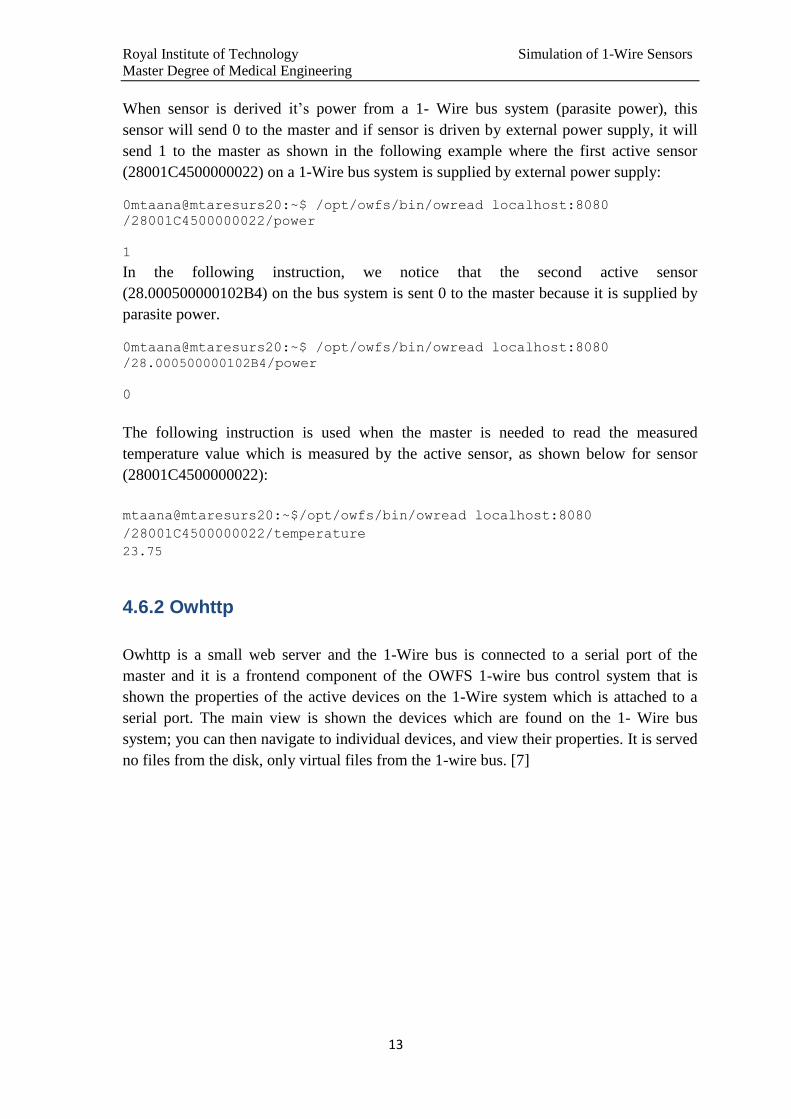
When sensor is derived it’s power from a 1- Wire bus system (parasite power), this
sensor will send 0 to the master and if sensor is driven by external power supply, it will
send 1 to the master as shown in the following example where the first active sensor
(28001C4500000022) on a 1-Wire bus system is supplied by external power supply:
0mtaana@mtaresurs20:~$ /opt/owfs/bin/owread localhost:8080
/28001C4500000022/power
1
In the following instruction, we notice that the second active sensor
(28.000500000102B4) on the bus system is sent 0 to the master because it is supplied by
parasite power.
0mtaana@mtaresurs20:~$ /opt/owfs/bin/owread localhost:8080
/28.000500000102B4/power
0
The following instruction is used when the master is needed to read the measured
temperature value which is measured by the active sensor, as shown below for sensor
(28001C4500000022):
mtaana@mtaresurs20:~$/opt/owfs/bin/owread localhost:8080
/28001C4500000022/temperature
23.75
4.6.2 Owhttp
Owhttp is a small web server and the 1-Wire bus is connected to a serial port of the
master and it is a frontend component of the OWFS 1-wire bus control system that is
shown the properties of the active devices on the 1-Wire system which is attached to a
serial port. The main view is shown the devices which are found on the 1- Wire bus
system; you can then navigate to individual devices, and view their properties. It is served
no files from the disk, only virtual files from the 1-wire bus. [7]
Royal Institute of Technology Simulation of 1-Wire Sensors
Master Degree of Medical Engineering
14
5. EXPLANATION THE CONNECTION AND THE
SIMULATION of ARDUINO ON THE 1-WIRE BUS
SYSTEM.
In this chapter, I will explain the types of connections and the simulation of the micro-
processor (Arduino) on the 1-Wire bus system as shown in the hard code in Appendix A.
Arduino is programmed to work as a temperature sensor (DS18B20) and this sensor is a
digital temperature sensor. Its resolution, which is programmed in the microprocessor, is
12 bits in order to get the minimum increment in the measured temperature value
0.0625°C.
There are two types of connection to connect the microprocessor to the 1- wire bus as
shown in Fig. 5.1. By following the hard code steps shown on page 15, we see which pin
has become the output pin of the sensor while the diode is used or the transistor is
connected with the microprocessor to be used as a switch between the input and the
output pin of the sensor to prevent any conflict between them.
1. Connecting the diode between the input pin (pin 2) and the output pin (pin 3) of the
microprocessor as a switch to prevent the conflict between the input and the output
signal.
These two pins (pin 2) and (pin 3) are connected to the 1-wire bus and represent the sense
pin input and sense pin output respectively.
When the sense pin output (pin 3) is high, the 1-wire bus is high also (+5V.) and vice
versa.
2. Connecting the transistor to work as a switch between the input pin (pin 2) and the
output pin (pin 6) of the microprocessor and representing the sense pin input and sense
pin output respectively.
If the sense output pin is high, the signal from the microprocessor is driven through the
base to the emitter of the transistor which is connected to the ground so that the 1-wire
bus signal is driven from the collector to the emitter and the bus becomes low.
However, if the sense output pin is low, the transistor is not working (open circuit) and
there is no signal from the sense output pin to the ground so that the 1-wire bus is high
(+5V.) = power supply.

Royal Institute of Technology Simulation of 1-Wire Sensors
Master Degree of Medical Engineering
15
+5V.
R
SensePinIn 1-Wire bus
SensePinOut
+5V.
R
SensePinIn 1-Wire bus
R
SensePinOut
Fig.5.1. Connections types of the microprocessor with the 1-Wire bus.
There are different 1-Wire bus commands which defined in this work thesis as the
following:
#define READ_ROM 0x33 // De olika 1-wire kommandona
#define MATCH_ROM 0x55
#define SEARCH_ROM 0xF0
#define ALARM_SEARCH_ROM 0xEC
#define SKIP_ROM 0xCC
#define READ_DEVICETYPE 0x03
#define WRITE_DEVICEID 0x04
#define WRITE_TIMESLOT 0x05
#define WRITE_SCRATCHPAD 0x4E
#define READ_SCRATCHPAD 0xBE
#define COPY_SCRATCHPAD 0x48
#define CONVERT_T 0x44
#define RECALL 0xB8
#define READ_POWER_SUPPLY 0xB4
#define REMOVE_NODE 0x06
In this work thesis, I specified some pins of microprocessor to work as the input and
output pin during writing the hard code and these pins are used to connect the micro-
processor on a 1-Wire bus system and to control all the signals from and to the micro-
processor. I noticed that there is one pin as an input pin (sensePinIn) and there are two
2
µP
3
2
µP
6
6

Royal Institute of Technology Simulation of 1-Wire Sensors
Master Degree of Medical Engineering
16
pins as an output pin (sensePinOut and ledPin) where ledPin is a pin no.13 and
sensePinOut is depended on the types of connection, pin ledPin2 is used to connect with
the Logic program to see the input and output signals of the microprocessor. We qualified
the variables by using VOLATILE instruction before specification the data types to these
variables, as show below.
// LED connected to digital pin 13
volatile int ledPin = 13;
volatile int ledPin2 = 5;
// This is the INT0 Pin of the ATMega8
volatile int sensePinIn = 2;
volatile int sensePinOut = SENSE_PORT_OUT;
There are different states which used in the different parts of 1-wire program.
volatile enum states {
WAITING_FOR_RESET=0,
RESET,
GET_CMD,
SEARCH_ROM_BIT,
SEARCH_ROM_CMP_BIT,
SEARCH_ROM_READ_BIT, One wire states
MATCH_ROM_READ,
ANSWARE_READ,
GET_DATA,
READ_SCRATCHPAD_READ,
READ_POWER_SUPPLY_READ
The ROM_id of each sensor is a sensor ID, that contains the serial number of the sensor
and the size of ROM_id is 64 byte although the serial number of sensor is 64 bit, because
each bit of the serial number is become one byte during programming the slave. It has
been more easily and quickly during shift one bit of the ROM_id to the right side when
the slave is sent data to the master as shown below in the sample code of the first bit in
ROM_id of one sensor.
volatile byte ROM_id_01[64];
In this thesis, I specified the reference temperature, amplitude, period, types of power and
the shape of graph for measured temperature values (simulating) of 12 active sensors on a
1- Wire bus system as shown in following sample for sensor no. 1.
referenstemp [1] = 21.0;
parasitepower[1] = 0xff;
simulering [1] = 2; // Sinus
amplitud [1] = 8.0;

Royal Institute of Technology Simulation of 1-Wire Sensors
Master Degree of Medical Engineering
17
There are three timers and each timer is worked as Interrupt Service Routine (ISR) as
shown in following explanations.
The interrupt configuration of the Timer 1:
The Timer/ Counter1 Control Register A is in its normal port operation mode, when
COM1A1 is 0 (clear) and the COM1A1 controls the Output Compare pins OC1A
behavior so that OC1A pin is disconnected from timer operation (breaking PWM).
Where COM1A1 is a Compare Output Mode for Channel A and it is a bit 7 in the
TCCR1A.
bitClear(TCCR1A, COM1A1);
bitClear(TCCR1A, COM1A1);
bitClear(TCCR1A, COM1A1);
bitClear(TCCR1A, COM1A1);
The Timer/ Counter Mode of Operation is CTC (mode 4) with TOP set by register
OCR1A, allow us to set variable timing for the interrupt by writing new values to
OCR1A immediate,
Where WGM 10 = WGM11 = WGM13 = 0 and WGM 12 = 1
WGM10 and WGM11 are Waveform Generation Modes represents bit 0 and 1 of the
TCCR1A register and these two bits are combined with the WGM13 and WGM12 bits
found in the TCCR1B register, these bits control the counting sequence of the counter.
bitClear(TCCR1A, WGM10);
bitClear(TCCR1A, WGM11);
bitSet(TCCR1B, WGM12);
bitClear(TCCR1B, WGM13);
In the Timer / Counter1 Control Register C (TCCR1C),
The FOC1A/FOC1B bits are bit 7 and bit 6 respectively in TCCR1C and these bits are
only active when the WGM13:0 bits specifies a non-PWM mode.
Note that the FOC1A/FOC1B bits are implemented as strobes. Therefore it is the value
present in the COM1x1:0 bits that is determine the effect of the forced compare.
A FOC1A/FOC1B strobe will not generate any interrupt nor will it clear the timer in
Clear Timer on Compare match (CTC) mode using OCR1A as TOP.
The FOC1A/FOC1B bits are always read as zero (Disable).
/* Disable Force Output Compare for Channels A and B. */
bitClear(TCCR1C, FOC1A);
bitClear(TCCR1C, FOC1B);

Royal Institute of Technology Simulation of 1-Wire Sensors
Master Degree of Medical Engineering
18
Timer/Counter1, Input Capture Interrupt Disable.
The Timer/Counter1 Input Capture Interrupt is a bit 5 of the Timer/Counter1Interrupt
Mask Register (TIMSK1).
The Timer/Counter1 Input Capture Interrupt (ICIE1) is disabled when this bit is written
to zero, and the I-flag in the Status Register is reset (interrupts globally disable).The
Timer/Counter1 Input Capture Interrupt Disable.
bitClear(TIMSK1, ICIE1);
Timer/Counter1, Output Compare B Match Interrupt Disable.
Output Compare B Match Interrupt is a bit 2 of the Timer/Counter1 Interrupt Mask
Register (TIMSK1). When this bit is written to zero, and the I-flag in the Status Register
is reset (interrupts globally disabled), the Timer/Counter1 Output Compare B Match
interrupt is disabled.
bitClear(TIMSK1, OCIE1B);
Timer/Counter1, Output Compare A Match Interrupt disable.
Output Compare A Match Interrupt is a bit 1 of the Timer/Counter1Interrupt Mask
Register (TIMSK1). When this bit is written to disable, and the I-flag in the Status
Register is reset, the Timer/ Counter 1 Output Compare A Match interrupt is disabled.
bitClear(TIMSK1, OCIE1A);
Timer/Counter1, Overflow Interrupt Disable.
The Timer/Counter1, Overflow Interrupt (TOIE1) is a bit 0 of Timer/Counter1Interrupt
Mask Register (TIMSK1). When this bit is written to zero, and the I-flag in the Status
Register is reset, the Timer/Counter1 Overflow interrupt is disabled.
bitClear(TIMSK1, TOIE1);
To stop the Timer/Counter, we must clear all the Clock Select (CS12:0) bits where the
Timer/Counter can be clocked by an internal or an external clock source. The clock
source is selected by the Clock Select logic which is controlled by the Clock Select
(CS12:0) bits are located in the Timer/ Counter control Register B (TCCR1B).The Clock
Select (CS12:0) are bit 0 to 2 of Timer/Counter1 Control Register B (TCCR1B).
/* no clock */
bitClear(TCCR1B, CS10);
bitClear(TCCR1B, CS11);
bitClear(TCCR1B, CS12);

Royal Institute of Technology Simulation of 1-Wire Sensors
Master Degree of Medical Engineering
19
Timer 2: In this timer, the interrupt registers have been set and the interrupt configuration
is become able, as the following:
The Wave Generation Mode is in mode two, where WGM20 = WGM22 = 0 and WGM21
=1 and the Clock select (CS12:0) bits are set (High).
The Timer/Counter mode of operation is a pulse width modulation (PWM) and the
Output Compare Register (OCR2A) is equal TOP. The counter value (TCNT2) is
increased until it is matched OCR2A, and then the counter (TCNT2) is cleared.
TCCR2A = (1<<WGM21); // WGM22=0 + WGM21=1 + WGM20=0 = Mode2 (CTC)
bitSet(TCCR2B, CS20); // set prescaler to /1024
bitSet(TCCR2B, CS21);
bitSet(TCCR2B, CS22);
TCNT2 = 0; //clear counter
OCR2A = 0xf3; // set TOP (divisor)
Now, the Interrupt Service Routine (ISR) starts as shown below.
I have set interrupts to be enabled, calls ISR (TIMER2_COMPA_Vect), the OCEI2A is
High so that TIMSK2 is become High also and the slave is sent interrupt to the master
and the 1-Wire Bus is become High (+5V.) where ledPin (pin 13) is the output pin of the
sensor and it is connected to the LED, and ledPin2 (pin 5) is connected to the Logic
program to see all the signals which are driven on the 1-Wire bus between the master and
the slave.
// Starts the ISR
TIMSK2=(1<<OCIE2A); // set interrupts=enabled (calls ISR(TIMER2_COMPA_vect)
sei();
digitalWrite(ledPin,HIGH);
digitalWrite(ledPin2,HIGH);
The next code steps are to generate the CRC as in Appendix A.
The CRC is provided the bus master with a method to check the data validation when the
data is read from the sensor. The bus master could re-calculate the CRC and compared it
to the CRC (Rom or Scratchpad) from the sensor by using the polynomial generator as
the following:
CRC = X8 + X5 + X4 + 1

Royal Institute of Technology Simulation of 1-Wire Sensors
Master Degree of Medical Engineering
20
The slave is sent the Cyclic Redundancy Check (CRC) to the master when it is provided
the master with the contents of the ROM code or the contents of the Scratchpad memory
as the following:
The ROM code CRC is calculated from the first 56 bits of the ROM code and is
contained in the most significant byte of the ROM. The scratchpad CRC is calculated
from the data stored in the scratchpad, and therefore its value is changed when the data in
the scratchpad is also changed. To verify that the data has been read correctly from the
slave, the bus master must re-calculate the CRC from the received data and then
compares this value to either the CRC value of ROM code for ROM reads or to the CRC
value of scratchpad for scratchpad reads. If the calculated CRC matches the read CRC,
the received data will be correct.
byte crc8(volatile byte *addr, byte len) {
byte crc = 0;
while (len--) {
byte inbyte = *addr++;
for (byte i = 8; i; i--) {
byte mix = (crc ^ inbyte) & 0x01;
crc >>= 1;
if (mix) crc ^= 0x8C;
inbyte >>= 1;
}
}
return crc;
}
int incomingByte = 0; // for incoming serial data

Royal Institute of Technology Simulation of 1-Wire Sensors
Master Degree of Medical Engineering
21
The diagram below consists of a shift register and XOR gates, and the shift register bits
are initialized to 0. Starting with the least significant bit of the ROM code or the least
significant bit of byte 0 in the scratchpad, one bit at a time should shifted into the shift
register. After shifting in the 56th bit from the ROM or the most significant bit of byte 7
from the scratchpad, the polynomial generator will contain the re-calculated CRC, then
the 8-bit ROM code or scratchpad CRC from the DS18B20 must be shifted into the
circuit. At this point, if the re-calculated CRC is correct, all contents of the shift register
will be 0s.
Input
XOR XOR
MSB LSB
Fig.5.2 CRC Generator.
The sensors on the bus are powered by parasite powered or by external power supply, and
the program steps in Appendix A are to check if the sensor is powered by 1-wire bus
(parasite power) or its powered by the external power supply and explain how the master
is communicated with the sensors to read the measured temperature value from the
actives sensors.
When the active sensor is powered by parasite powered, the master must transmit
Convert T [44h] and convert_t == 1 to one sensor only and the master must wait at least
600 msec. and convert_t_cnt == 0. The master is sent Read Scratchpad command to the
active sensor to bring the measured temperature value and all contains of the 9 bytes of
the sensor’s Scratchpad memory. If the master did not wait 600msec. before sending
command (e.g. Read Scratchpad) to the slave, the master will get 85°C (0550h) and this
value represents error in the measured temperature value because the sensor did not finish
compute the temperature value.
However, when the sensor is powered by external power supplies, the master is
transmited Convert_T to all sensors on the 1- Wire Bus at the same time and also the
master must wait at least 600 msec before sending any command from the master to the
slave and the counter of Convert_T is become 0 (convert_t_cnt = 0). If the master did not
wait 600msec. before sending command (e.g. Read Scratchpad) to the slave, the master
will get 85°C (0550h) and when this sensor did not has an old temperature value but if
the sensor has an old temperature value, the master will get this old temperature value
which is saved in the memory of this sensor and this temperature value did not represent

Royal Institute of Technology Simulation of 1-Wire Sensors
Master Degree of Medical Engineering
22
a real temperature value at this time because the sensor is not finished for computing the
temperature value.
The period of the measured temperature values are compared with timer (myTimer2) to
draw the temperature value, and the period of this timer is 4 hours (FFFFh).
The measured temperature value from the active sensor is in decimal (f) and it’s divided
on the temperature resolution (0.0625) to find the temperature value in bits (x) as shown
in the following sample of one sensor.
if (parasitepower[active_sensor] == 0) {
if (convert_t[active_sensor] == 1 && convert_t_cnt[active_sensor] == 0) {
// Sinus
if (simulering[active_sensor] == 2) {
f= (sin((2 * PI/ (float(period[active_sensor]) + 1)) * (myTimer2 & period
[active_sensor])) * amplitud[active_sensor] / 2) + referenstemp[active_sensor];
x = f / 0.0625;
Temperatur[active_sensor] = x
The measured temperature values were drawn in different shapes (sinus, ramp up, ramp
down, triangle, pulse and normal curves) and every sensor has a specific reference
temperature value, simulation, period and the amplitude of the measured temperature
values of active sensor on the bus are ±4 degree from the reference temperature value as
shown in Appendix B.
After finished one period of measured values of each sensor, and the graphic of the
measured temperature values is drawn by Open Logger program and by others drive bus
programs then convert_t of this active sensor is become 0.
convert_t[active_sensor] = 0;
The needed time for the convert_t_cnt to be equal 0 is 600 msec. in order to the master
begin read the temperature values which are measured by the active sensor then these
measured temperature are drawn by Open Logger program and by others drive bus
programs in the master computer.
We have three counters (myFac), (myTimer2) and (convert_t_cnt) in the interrupt routine
(TIMER2_COMPA_vect) to compute the time that is need for the master to wait before
get a measured temperature value which is measured by the active sensor.
myFac counter is equal to 15 after 250 msec. then the myTimer2 is begun increase and
myFac is become equal 0. When (convert_t_cnt > 0), this counter is begun decrease from
36 to 0 and it is needed 600 msec. (16, 6667 msec. * 36 = 600 msec.).

Royal Institute of Technology Simulation of 1-Wire Sensors
Master Degree of Medical Engineering
23
// Install the interrupt routine.
ISR (TIMER2_COMPA_vect) {
myFac++;
if (myFac > 15) {
myTimer2++; //250ms /15= 16ms
myFac = 0;
}
if (convert_t_cnt[active_sensor] > 0) {
convert_t_cnt[active_sensor] --;
}
}
When the master is got a measured temperature value from the slave, the INT0 will be
disabled (pin 2 = 0) where pin 2 is the sense port input (sensePinIn) and the 1-Wire Bus is
become low and Convert_t = 0 only when the sensor is powered by parasite power.
Case GET_CMD is to send command to the master from the slave. The olow_cmd is
shifted one bit to the right and then it waits 10 msec. to see the value of the sensePinIn
(Pin 2). If the sensePinIn is High, the olow_cmd will be read high. The olow_cmd is
shifted to the next bit and the bit_index is increased until it is become more than 7, so the
command is become complete and in this time the byte_index and bit_index = 0, where
the slave is sent one bit in each time slot on the 1-Wire Bus. In this case, the master is
received the complete command from the slave.
switch(onewire_state) {
case GET_CMD:
/ / Step olow_cmd one step to the right
olow_cmd >>= 1; // master bus command
delayMicroseconds(10);
if (digitalRead(sensePinIn)) {
// Läst en etta
olow_cmd |= 0x80;
}
bit_index++;
if (bit_index > 7) {
Royal Institute of Technology Simulation of 1-Wire Sensors
Master Degree of Medical Engineering
24
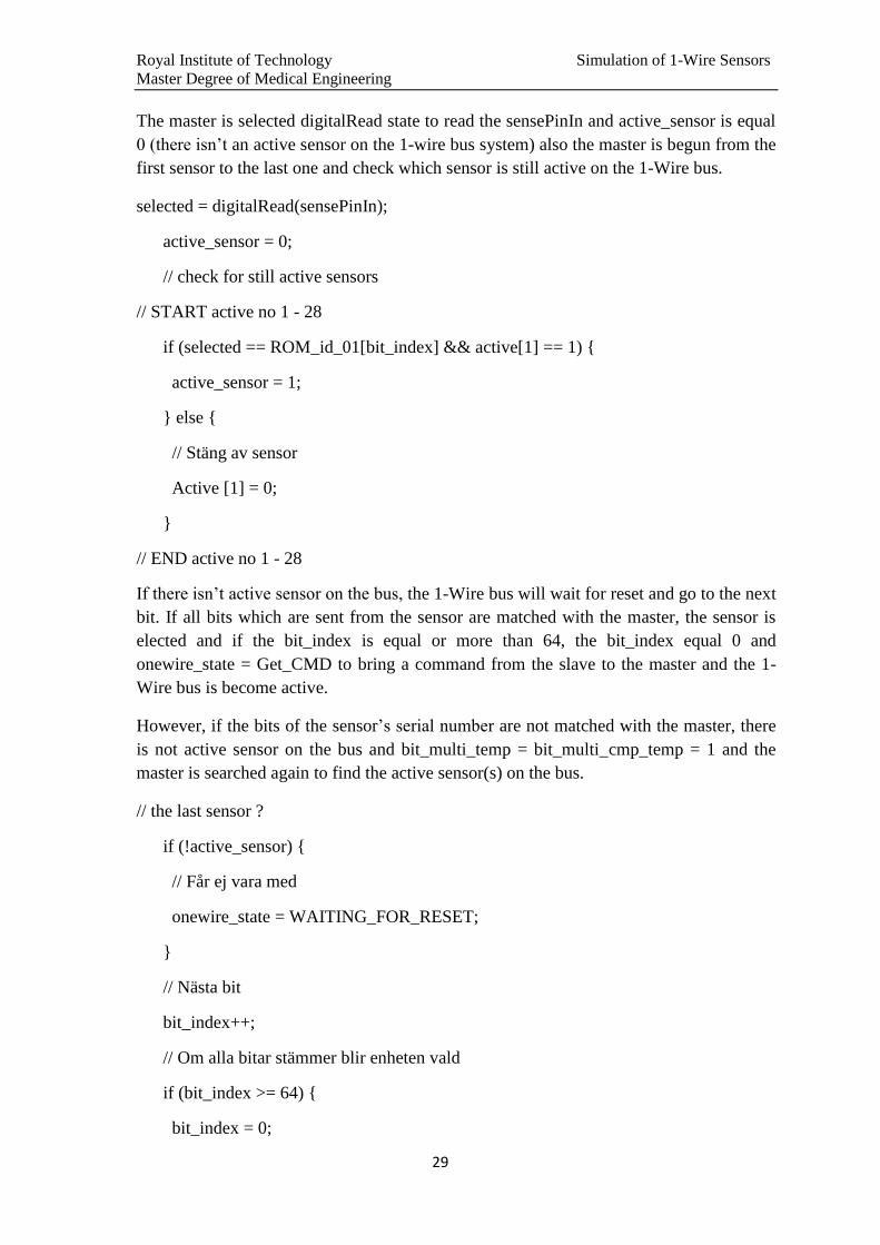
// Commando komplett
byte_index = 0;
bit_index = 0;
break;
If the 1-Wire bus is High, it means that it is active, the switch is become olow_cmd and
the master is issued Read Scratchpad to read the measured value (1st and 2
nd bytes of the
scratchpad) and CRC code (9th
byte of the scratchpad of DS18B20). The onewire _state =
Read_Scratchpad_Read. The bit _temp is the first bit of the Scratchpad [byte_index]
where the Scratchpad [byte_index] is shifted before to the right depending on the value of
bit_index.
if (ow_active) {
switch (olow_cmd) {
case READ_SCRATCHPAD:
SCRATCHPAD[0] = Temperatur[active_sensor] & 0x00FF;
SCRATCHPAD[1] = (Temperatur[active_sensor] >> 8) & 0x00FF;
crc8_temp = crc8(SCRATCHPAD, 8);
SCRATCHPAD[8] = crc8_temp;
onewire_state = READ_SCRATCHPAD_READ;
bit_temp = (SCRATCHPAD[byte_index] >> bit_index) & 0b00000001;
break;
In the case of READ_POWER_SUPPLY, the 1-Wire bus state is become
READ_POWER_SUPPLY_READ
The bit _temp is a first bit of the shifted parasitepower[byte_index] where the
parasitepower[byte_index] is shifted to the right depending on the value of bit_index.
Case READ_POWER_SUPPLY:
onewire_state = READ_POWER_SUPPLY_READ;
bit_temp = (parasitepower[active_sensor] >> bit_index) & 0b00000001;
break;
Case CONVERT_T:
if (parasitepower[active_sensor] == 0){
Temperatur[active_sensor] = 0x0550;

Royal Institute of Technology Simulation of 1-Wire Sensors
Master Degree of Medical Engineering
25
}
power_off[active_sensor] = 0;
convert_t[active_sensor] = 1;
convert_t_cnt[active_sensor] = 36;
TemperaturCnt[active_sensor]++;
break;
If the 1-Wire Bus is not active (there isn’t any active sensor on the 1-Wire Bus), the
master will send Search Rom to identify the Rom codes of all the slave devices on the bus
and it allows the master to determine the number of salves and their slave types. The state
of the 1-Wire Bus is Search Rom Bit and the sensors are prepare answer to the master
where bit_multi_temp = bit_multi_cmp_temp = 1.
// Not selected on 1-wire
switch (olow_cmd) {
case SEARCH_ROM:
onewire_state = SEARCH_ROM_BIT;
// Förbered svaret
//digitalWrite(ledPin2,LOW);
bit_multi_temp = 1;
bit_multi_cmp_temp = 1;
// START no 1 - 28
if (active[1]) {
if (ROM_id_01[bit_index]) {
bit_multi_cmp_temp = 0;
} else {
bit_multi_temp = 0;
}
}
If the sensor is active, it will send bit_multi_temp or bit-multi to the master depending on
the value of the ROM_id [bit_index] of this active sensor.
If the Rom_id [bit_index] of this sensor is High (“1”) and the bit_multi_temp is High
(“1”), the complement value of this bit will be Low (“0”) (bit_multi_cmp_temp = 0), and
if the Rom_id [bit_index] is Low (“0”) that the bit_multi_temp will become low (“0”)

Royal Institute of Technology Simulation of 1-Wire Sensors
Master Degree of Medical Engineering
26
and the sensor will send (“0”) on the 1-Wire Bus. The following code is for first sensor
on a 1-wire bus and it is same code for all sensors on the 1-Wire bus system.
// START no 1 - 28
if (active[1]) {
if (ROM_id_01[bit_index]) {
bit_multi_cmp_temp = 0;
} else {
bit_multi_temp = 0;
}
}
// END no 1 – 28
After finished the master for finding active sensor(s) on the 1-Wire bus, ledPin2 (pin 5) is
become high and the 1-Wire bus is become in Match_Rom_read and it is prepared the
response from the sensor and the LedPin2 is become “Low”. The bit_multi_temp =
bit_multi_cmp_temp=1 and the master is begun again to check which sensor is active on
the 1-Wire bus system.
//digitalWrite(ledPin2,HIGH);
break;
case SKIP_ROM:
break;
case MATCH_ROM:
onewire_state = MATCH_ROM_READ;
// Förbered svaret
//digitalWrite(ledPin2,LOW);
bit_multi_temp = 1;
bit_multi_cmp_temp = 1;
// START no 1 - 28
if (active[1]) {
if (ROM_id_01[bit_index]) {
bit_multi_cmp_temp = 0;
} else {

Royal Institute of Technology Simulation of 1-Wire Sensors
Master Degree of Medical Engineering
27
bit_multi_temp = 0;
}
}
// END no 1 – 28
break;
onewire_state = WAITING_FOR_RESET;
break;
If the bit_multi_temp is High (“1”), this mean there is sensor active on the bus and this
active sensor is sent respond by put its value in a bit on the bus. If its value is Low (“0”),
there isn’t an active sensor on the bus is sent a respond to the master. If the sensor is
connected within a transistor on the bus, the SENSE_PORT_OUT is High (“1”) and
PORTD is Low (“0”) and if the sensor is connected within diode on the bus, the
SENE_PORT_OUT is Low (“0”) and PORTD is become Low (“0”) and the master must
be waited 20 µsec. to become the 1-Wire bus High (“1”). The state of the bus is become
Search Rom on the Complement Bit (SERACH_ROM_CMP_BIT), then the sensor
should respond with contrary to the concerned bits on the bus and the same procedure
steps of the SEARCH_ROM_BIT state is repeated. The 1-Wire bus state is become
(SEARCH_ROM_READ_BIT) and the master is waited 10µsec. to become the bus
(SEARCH_ROM_BIT) and OLOW is typed which bit that the sensor is had to continue
answering. The master is selected digitalRead state to read the sensePinIn and
active_sensor is equal 0 (there isn’t an active sensor on the 1-wire bus) also it is begun
from the first sensor to the last one and it is checked which sensor is stilled active on the
1-Wire bus as shown in the following hard code:
// Then the device should respond with the opposite of the bit on the bus in case
SEARCH_ROM_BIT:
/ / At SEARCH_ROM the device should put its value at the bit on the bus
if (bit_multi_temp) {
} else {
#if defined (TRANSISTOR)
PORTD = PORTD | SENSE_PORT_OUT_HIGH;
#else
PORTD = PORTD & SENSE_PORT_OUT_LOW;
#endif
delayMicroseconds(20);
#if defined (TRANSISTOR)

Royal Institute of Technology Simulation of 1-Wire Sensors
Master Degree of Medical Engineering
28
PORTD = PORTD & SENSE_PORT_OUT_LOW;
#else
PORTD = PORTD | SENSE_PORT_OUT_HIGH;
#endif
}
onewire_state = SEARCH_ROM_CMP_BIT;
break;
case SEARCH_ROM_CMP_BIT:
if (bit_multi_cmp_temp) {
} else {
#if defined(TRANSISTOR)
PORTD = PORTD | SENSE_PORT_OUT_HIGH;
#else
PORTD = PORTD & SENSE_PORT_OUT_LOW;
#endif
delayMicroseconds(20);
#if defined (TRANSISTOR)
PORTD = PORTD & SENSE_PORT_OUT_LOW;
#else
PORTD = PORTD | SENSE_PORT_OUT_HIGH;
#endif
}
onewire_state = SEARCH_ROM_READ_BIT;
break;
case SEARCH_ROM_READ_BIT:
delayMicroseconds(10);
//--digitalWrite(ledPin2,LOW);
onewire_state = SEARCH_ROM_BIT;
Royal Institute of Technology Simulation of 1-Wire Sensors
Master Degree of Medical Engineering
29
The master is selected digitalRead state to read the sensePinIn and active_sensor is equal
0 (there isn’t an active sensor on the 1-wire bus system) also the master is begun from the
first sensor to the last one and check which sensor is still active on the 1-Wire bus.
selected = digitalRead(sensePinIn);
active_sensor = 0;
// check for still active sensors
// START active no 1 - 28
if (selected == ROM_id_01[bit_index] && active[1] == 1) {
active_sensor = 1;
} else {
// Stäng av sensor
Active [1] = 0;
}
// END active no 1 - 28
If there isn’t active sensor on the bus, the 1-Wire bus will wait for reset and go to the next
bit. If all bits which are sent from the sensor are matched with the master, the sensor is
elected and if the bit_index is equal or more than 64, the bit_index equal 0 and
onewire_state = Get_CMD to bring a command from the slave to the master and the 1-
Wire bus is become active.
However, if the bits of the sensor’s serial number are not matched with the master, there
is not active sensor on the bus and bit_multi_temp = bit_multi_cmp_temp = 1 and the
master is searched again to find the active sensor(s) on the bus.
// the last sensor ?
if (!active_sensor) {
// Får ej vara med
onewire_state = WAITING_FOR_RESET;
}
// Nästa bit
bit_index++;
// Om alla bitar stämmer blir enheten vald
if (bit_index >= 64) {
bit_index = 0;

Royal Institute of Technology Simulation of 1-Wire Sensors
Master Degree of Medical Engineering
30
ow_active = 1;
onewire_state = GET_CMD;
} else {
bit_multi_temp = 1;
bit_multi_cmp_temp = 1;
// START no 1 - 28
if (active[1]) {
if (ROM_id_01[bit_index]) {
bit_multi_cmp_temp = 0;
} else {
bit_multi_temp = 0;
}
}
// END no 1 - 28
The master bus is in MATCH_ROM_READ to see if the active sensor on the bus is
matched with master or not and the master is waited 15 µsec. to write which bit that the
sensor is had to continue the answer. If the Sense_Pin_In (pin 2) is High (“1”), a selected
is become equal 1, this mean that the master is finished from this sensor and the
active_sensor is become equal 0 (there isn’t active sensor) and the master is checked
again on an active sensor among all sensors on the 1-Wire bus and the code steps are
repeated again same before.
case MATCH_ROM_READ:
delayMicroseconds(15);
//--digitalWrite(ledPin2,LOW);
/ / Olow then writes the bit that entity must have in order to continue to respond
// selected = digitalRead(sensePinIn);
selected = PIND & 0x04; //Pin 2 (INT0) is High
if (selected > 0) {
selected = 1;
}
active_sensor = 0;

Royal Institute of Technology Simulation of 1-Wire Sensors
Master Degree of Medical Engineering
31
// check for still active sensors
// START active no 1 - 28
if (selected == ROM_id_01[bit_index] && active[1] == 1) {
active_sensor = 1;
} else {
// Stäng av sensor
active[1] = 0;
}
// END active no 1 - 28
when the byte_index is not equal 8, the SCRATCHPAD [bit_index] is shifted to the right
with a value equal to the bit_index and compare with 0b00000001 to get the first bit only
and this value is represented the bit_temp, then a state of the bus is become
WAIT_FOR_RESET state.
case READ_SCRATCHPAD_READ:
if (bit_temp) {
} else {
#if defined (TRANSISTOR)
PORTD = PORTD | SENSE_PORT_OUT_HIGH;
#else
PORTD = PORTD & SENSE_PORT_OUT_LOW;
#endif
}
delayMicroseconds(20);
#if defined(TRANSISTOR)
PORTD = PORTD & SENSE_PORT_OUT_LOW;
#else
PORTD = PORTD | SENSE_PORT_OUT_HIGH;
#endif
bit_index++;
if (bit_index > 7) {

Royal Institute of Technology Simulation of 1-Wire Sensors
Master Degree of Medical Engineering
32
bit_index = 0;
byte_index++;
}
if (byte_index > 8) {
bit_index = 0;
ow_active = 1;
onewire_state = GET_CMD;
} else {
bit_temp = (SCRATCHPAD[byte_index] >> bit_index) & 0b00000001;
}
break;
The master bus is in READ_POWER_SUPPLY_READ to see if the sensor is powered by
parasite power or by external power supply.
When the sensor is powered by parasite power, it is sent 0 to the master and if the sensor
is powered by external power supply, it is sent 1 to master, so that the master is known a
type of the power supply for every active sensor on the 1-Wire bus system.
case READ_POWER_SUPPLY_READ:
if (bit_temp) {
} else {
#if defined(TRANSISTOR)
PORTD = PORTD | SENSE_PORT_OUT_HIGH;
#else
PORTD = PORTD & SENSE_PORT_OUT_LOW;
#endif
}
delayMicroseconds(20);
#if defined(TRANSISTOR)
PORTD = PORTD & SENSE_PORT_OUT_LOW;
#else
PORTD = PORTD | SENSE_PORT_OUT_HIGH;

Royal Institute of Technology Simulation of 1-Wire Sensors
Master Degree of Medical Engineering
33
#endif
bit_index++;
if (bit_index > 7) {
bit_index = 0;
byte_index++;
}
if (byte_index > 0) { //Read Power Supply is one byte.
bit_index = 0;
ow_active = 1;
onewire_state = GET_CMD;
} else {
bit_temp = (parasitepower[active_sensor] >> bit_index) & 0b00000001;
}
break;
When the bus is reset, the External Interrupt Control Register A (EICRA) and The
External Interrupt 0 is activated by the external pin INT0. If the I-flag and the
corresponding interrupt mask are set, the level and edges on the external INT0 pin that is
activated the interrupt where the interrupt is an Interrupt Sense Control (ISC) and I set
ISC00 and ISC01 to High (“1”) so that the rising edge of INT0 is generated an interrupt
request and the EICRA = 1, active_sensor = 0 and bit_index = 0 and active
[active_sensor] =1 for all 12 sensors
case RESET:
// External Interrupt Control Register A - The falling edge of INT0 generates an
interrupt request
EICRA |= (1 << ISC01); // 1
EICRA |= (1 << ISC00); // 1
active_sensor = 0;
bit_index = 0;
active[1] = 1;
active[2] = 1;

Royal Institute of Technology Simulation of 1-Wire Sensors
Master Degree of Medical Engineering
34
active[3] = 1;
active[4] = 1;
active[5] = 1;
active[6] = 1;
active[7] = 1;
active[8] = 1;
active[9] = 1;
active[10] = 1;
active[11] = 1;
active[12] = 1;
Also I must be checked the connection of the slave when I used a transistor or diode
during the connection of the microprocessor on the 1-Wire bus to find the state of
PORTD.
#if defined(TRANSISTOR)
PORTD = PORTD | SENSE_PORT_OUT_HIGH;
#else
PORTD = PORTD & SENSE_PORT_OUT_LOW;
#endif
delayMicroseconds(100);
#if defined (TRANSISTOR)
PORTD = PORTD & SENSE_PORT_OUT_LOW;
#else
PORTD = PORTD | SENSE_PORT_OUT_HIGH;
#endif
When the bus is become High (“1”), the state of the1-Wire bus is become on GET_CMD
to get a command (the measured temperature value) from a slave to the master.
onewire_state = GET_CMD;
The clock select bits (CS) is selected a clock source to be used by Timer/ Counter1 and
the clock is set on the clkI/O/8(from prescaler), where CS10 = CS12 = 0(reset) and CS11
= 1(set) in the Timer/counter1 Control Register B (TCCR1B).

Royal Institute of Technology Simulation of 1-Wire Sensors
Master Degree of Medical Engineering
35
In the Timer/Counter1 Interrupt mask Register (TIMSK1), the Output Compare A Match
interrupt enable (OCIE1A) is set and the Timer/Counter (TCNT1) is cleared because its
value reached to the maximum value.
In the External Interrupt Control Register A, the Interrupt Sense Control = 0, ISC00 = 0
and ISC01 = 1 where the falling edge of INT0 is generated an interrupt request and the
low level interrupt must be held until the completion of the currently executing
instruction to generate an interrupt and The value of the INT0 pin is sampled before
detecting edges.
The External Interrupt Flag Register (EIFR), the flag is cleared when INTF0 = 1 because
INT0 is configured as a level interrupt and the External interrupt Mask register (EIMSK)
is enable (“1”) When the INT0 bit is set (“1”) then the Timer/ Counter (TCNT1) is reset
(“0”).
/* set the clock prescaler to /8. */
bitClear(TCCR1B, CS10); // CS10 = 0
bitSet(TCCR1B, CS11); //CS 11= 1
bitClear(TCCR1B, CS12); //CS12 = 0
//Compare A Match Interrupt
bitSet(TIMSK1, OCIE1A);
TCNT1 = 0x0000;
// External Interrupt Control Register A - The falling edge of INT0 generates an
interrupt request
EICRA |= (1 << ISC01); // 1
EICRA &= ~(1 << ISC00); // 0
// External Interrupt Flag Register - clear int0 flag INTF0
EIFR |= (1 << INTF0);
// External Interrupt Mask Register - enable INT0
EIMSK |= (1 << INT0);
TCNT1 = 0x0000;

Royal Institute of Technology Simulation of 1-Wire Sensors
Master Degree of Medical Engineering
36
6. RESULTS
In this project, the microprocessor (Arduino) was programmed to work as a 12
temperature sensors type (DS18B20). These sensors were designed to work as slaves on a
1-Wire bus system; the microprocessor was connected to the serial port of the master
(PC).
The measured temperature values of the12 sensors were validated by using the following
four different drive bus programs: OLOW, One Wire Viewer, Digitemp and OWFS.
After the validation test for the measured temperature values of 12 sensors, I noticed that
the master is displayed the measured values from the active sensor every one minute and
these values are very similar in the four drive buss programs as shown in Appendix B.
During the validation test, I noticed that the sensors are driven by an external power
supply. The master will receive measured temperature values from these sensors faster
than if sensors which are driven by parasite power, because the master sends convert_T to
all active sensors on the 1-Wire bus system. Then these sensors begin to compute the
temperature values during 600 msec. and these values are sent to the master to read and
be monitored. But if many sensors are driven by parasite power on the 1-Wire bus, the
master sends convert_T to only one active sensor on the 1-Wire bus system and the
master must wait 600 msec. until the sensors have finished measuring temperature values.
Then the master sends convert-T to another active sensor and the procedure will repeat
itself with all active sensors which are driven by parasite power. In the both types of
power supply, the master displays the measured temperature values of all active sensors
every one minute.
In the validation test of the measured temperature values, the microprocessor (Aduino) is
tested with different drive bus programs which are used in the master computers at the
Karolinska University Hospital. This test is completed to see if this type of
microprocessor can be enabled to work as a temperature sensor (DS18B20) with the same
efficiency and get same measured temperature values during same time intervals with
different drive bus programs such as DigiTemp, One Wire Viewer, OLOW and OWFS.

Royal Institute of Technology Simulation of 1-Wire Sensors
Master Degree of Medical Engineering
37
7. CONCLUSIONS
This thesis was started to find out how we can program the microprocessor (Arduino) to
work as the temperature sensor (DS18B20) and to be connected as a slave on the 1- Wire
bus with the master. The work was carried out with the programs and methods introduced
during the Master program. The research had a practical approach. On the one hand, we
used the Arduino data sheet and its open source programming language to write the hard
code for the microprocessor and also used a data sheet of the temperature sensor
(DS18B20) to use as reference, and on the other hand participated observations were
necessary, a big volume of field work was conducted by my supervisor.
During the work thesis, we concluded that the microprocessor (Arduino) is a suitable
microprocessor to work as a temperature sensor on 1- Wire bus system and it has an open
source code and it can be easily programmed and flexible to use hardware with it, to
create the interactive objects and the user can develop this project depending on the
requirements of his/ her work in the future.
The 1-Wire interface is interesting because it allows the user to connect a number of
sensors by using a single wire technology (plus a ground return), where the sensors are
"addressable" and each sensor is assigned a unique (world-wide) 64-bit code. This means
even if multiple sensors are connected to the same pair of wires they can be addressed
individually.
In the 1-Wire bus there are two types of powering, the first is when the sensor is powered
by the 1-Wire bus (parasite power) and the second is when it is powered from the
external power supply and the master bus may not know what type of powering the
sensor is using. The master requires specific information about the powering state of the
sensors to determine whether the strong bus pull-up should be used during temperature
conversions during the read time slot or not. Parasite powered sensors will lower the bus
and the master knows that it must supply the strong pull-up on the 1-Wire bus to make
the bus high during temperature conversion, and externally powered sensors will let the
bus remain high.
The process is to simulate the microprocessor to work as the temperature sensor type
(DS18B20) with a master on a 1-Wire bus which is presented by the hard code as shown
in Appendix A. We found also the best prototype of 1- Wire simulator and associated
components to get the best measured data by the sensors.
In the project, the important task is to simulate many sensors simultaneously and to find
the optimal number of temperature sensors on the 1-Wire bus. The most effective
numbers of sensors in the microprocessor are twelve, with high performance and more
reliability and high sensitive to measure different temperature values, but when the

Royal Institute of Technology Simulation of 1-Wire Sensors
Master Degree of Medical Engineering
38
number of sensors is more than twelve, the microprocessor cannot measure any
temperature value.
The temperature values which are measured by the sensors are based on a scientifically
and practically proved method of the microprocessor on the 1-Wire bus corresponding on
the properties of temperature sensor (DS18B20).
The measured values are drawn in different shapes of curves with different period of time
(e.g.: sinusoidal, ramp up, ramp down, saw tooth, square, linear). The user can make
some changes easily within the program to change the reference temperature, period and
the shape of the curve for each sensor.
In the validation test, I noticed that the microprocessor is worked very well to get the
same measured temperature values during the same time intervals for the same
temperature sensor, when this sensor is in communication with different drive bus
programs. This process was repeated with all 12 active sensors so that we were able to
validate all the measured temperature values by these 12 active sensors.
Arduino is suitable to work and communicate with different drive bus programs and
measure correct/accurate temperature values with different programs of master computers
which are using now in the Medical Technical Department at Karolinska University
Hospital.

Royal Institute of Technology Simulation of 1-Wire Sensors
Master Degree of Medical Engineering
39
REFERENCES
[1] http://www.maxim-ic.com/products/1-wire/, Maxim Integrated Products.
[Viewed on 30 – May - 2011 at 13:05].
[2] http://arduino.cc/, Arduino Co.
[Viewed on 1 – June - 2011 at 10:15].
[3] http://www.saleae.com/logic16/ , Saleae Logic.
[Viewed on 7 – June - 2011 at 09:00].
[4] http://www.maximic.com/products/ibutton/software/1wire/OneWireViewer.cfm,
Maxim Integrated Products. [Viewed on 17 – March - 2012 at 10:00].
[5] http://www.digitemp.com/ , Brian C. Lane. [Viewed on 20 – March - 2012 at 10:30]
[6] http://owfs.org/index.php?page=owfs, Mike Kalist.
[Viewed on 01 - April - 2012 at 11:00].
[7] http://owfs.org/index.php?page=owserver, Mike Kalist.
[Viewed on 05 - April - 2012 at 08:00].

Royal Institute of Technology Simulation of 1-Wire Sensors
Master Degree of Medical Engineering
40
APPENDICES

Royal Institute of Technology Simulation of 1-Wire Sensors
Master Degree of Medical Engineering
41
Appendix A. The Hard Code Program of Arduino.
extern "C" {
#include "WConstants.h"
// Definition of interrupt names
#include <avr/io.h>
// ISR interrupt service routine
#include <avr/interrupt.h>
#include <avr/pgmspace.h>
}
#define DIODE
//#define TRANSISTOR
#if defined(DIODE)
#define SENSE_PORT_OUT 3
#define SENSE_PORT_OUT_LOW 0xf7;
#define SENSE_PORT_OUT_HIGH 0x08;
#else
#define SENSE_PORT_OUT 6
#define SENSE_PORT_OUT_LOW 0xbf;
#define SENSE_PORT_OUT_HIGH 0x40;
#endif
// The various 1-wire commands
#define READ_ROM 0x33
#define MATCH_ROM 0x55
#define SEARCH_ROM 0xF0
#define ALARM_SEARCH_ROM 0xEC
#define SKIP_ROM 0xCC
#define READ_DEVICETYPE 0x03
#define WRITE_DEVICEID 0x04
#define WRITE_TIMESLOT 0x05
#define WRITE_SCRATCHPAD 0x4E
#define READ_SCRATCHPAD 0xBE
#define COPY_SCRATCHPAD 0x48
#define CONVERT_T 0x44
#define RECALL 0xB8
#define READ_POWER_SUPPLY 0xB4
#define REMOVE_NODE 0x06
// LED connected to digital pin 13
volatile int ledPin = 13;
volatile int ledPin2 = 5;
// This is the INT0 Pin of the ATMega8
volatile int sensePinIn = 2;
volatile int sensePinOut = SENSE_PORT_OUT;
volatile enum states {
WAITING_FOR_RESET=0,
RESET,
GET_CMD,
SEARCH_ROM_BIT,
SEARCH_ROM_CMP_BIT,
SEARCH_ROM_READ_BIT,
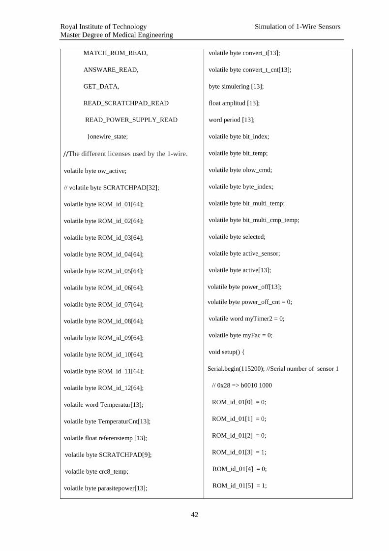
Royal Institute of Technology Simulation of 1-Wire Sensors
Master Degree of Medical Engineering
42
MATCH_ROM_READ,
ANSWARE_READ,
GET_DATA,
READ_SCRATCHPAD_READ
READ_POWER_SUPPLY_READ
}onewire_state;
//The different licenses used by the 1-wire.
volatile byte ow_active;
// volatile byte SCRATCHPAD[32];
volatile byte ROM_id_01[64];
volatile byte ROM_id_02[64];
volatile byte ROM_id_03[64];
volatile byte ROM_id_04[64];
volatile byte ROM_id_05[64];
volatile byte ROM_id_06[64];
volatile byte ROM_id_07[64];
volatile byte ROM_id_08[64];
volatile byte ROM_id_09[64];
volatile byte ROM_id_10[64];
volatile byte ROM_id_11[64];
volatile byte ROM_id_12[64];
volatile word Temperatur[13];
volatile byte TemperaturCnt[13];
volatile float referenstemp [13];
volatile byte SCRATCHPAD[9];
volatile byte crc8_temp;
volatile byte parasitepower[13];
volatile byte convert_t[13];
volatile byte convert_t_cnt[13];
byte simulering [13];
float amplitud [13];
word period [13];
volatile byte bit_index;
volatile byte bit_temp;
volatile byte olow_cmd;
volatile byte byte_index;
volatile byte bit_multi_temp;
volatile byte bit_multi_cmp_temp;
volatile byte selected;
volatile byte active_sensor;
volatile byte active[13];
volatile byte power_off[13];
volatile byte power_off_cnt = 0;
volatile word myTimer2 = 0;
volatile byte myFac = 0;
void setup() {
Serial.begin(115200); //Serial number of sensor 1
// 0x28 => b0010 1000
ROM_id_01[0] = 0;
ROM_id_01[1] = 0;
ROM_id_01[2] = 0;
ROM_id_01[3] = 1;
ROM_id_01[4] = 0;
ROM_id_01[5] = 1;
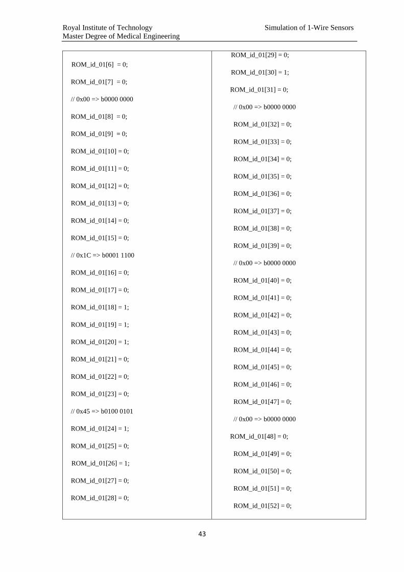
Royal Institute of Technology Simulation of 1-Wire Sensors
Master Degree of Medical Engineering
43
ROM_id_01[6] = 0;
ROM_id_01[7] = 0;
// 0x00 => b0000 0000
ROM_id_01[8] = 0;
ROM_id_01[9] = 0;
ROM_id_01[10] = 0;
ROM_id_01[11] = 0;
ROM_id_01[12] = 0;
ROM_id_01[13] = 0;
ROM_id_01[14] = 0;
ROM_id_01[15] = 0;
// 0x1C => b0001 1100
ROM_id_01[16] = 0;
ROM_id_01[17] = 0;
ROM_id_01[18] = 1;
ROM_id_01[19] = 1;
ROM_id_01[20] = 1;
ROM_id_01[21] = 0;
ROM_id_01[22] = 0;
ROM_id_01[23] = 0;
// 0x45 => b0100 0101
ROM_id_01[24] = 1;
ROM_id_01[25] = 0;
ROM_id_01[26] = 1;
ROM_id_01[27] = 0;
ROM_id_01[28] = 0;
ROM_id_01[29] = 0;
ROM_id_01[30] = 1;
ROM_id_01[31] = 0;
// 0x00 => b0000 0000
ROM_id_01[32] = 0;
ROM_id_01[33] = 0;
ROM_id_01[34] = 0;
ROM_id_01[35] = 0;
ROM_id_01[36] = 0;
ROM_id_01[37] = 0;
ROM_id_01[38] = 0;
ROM_id_01[39] = 0;
// 0x00 => b0000 0000
ROM_id_01[40] = 0;
ROM_id_01[41] = 0;
ROM_id_01[42] = 0;
ROM_id_01[43] = 0;
ROM_id_01[44] = 0;
ROM_id_01[45] = 0;
ROM_id_01[46] = 0;
ROM_id_01[47] = 0;
// 0x00 => b0000 0000
ROM_id_01[48] = 0;
ROM_id_01[49] = 0;
ROM_id_01[50] = 0;
ROM_id_01[51] = 0;
ROM_id_01[52] = 0;

Royal Institute of Technology Simulation of 1-Wire Sensors
Master Degree of Medical Engineering
44
ROM_id_01[53] = 0;
ROM_id_01[54] = 0;
ROM_id_01[55] = 0;
// 0x22 => b0010 0010
ROM_id_01[56] = 0;
ROM_id_01[57] = 1;
ROM_id_01[58] = 0;
ROM_id_01[59] = 0;
ROM_id_01[60] = 0;
ROM_id_01[61] = 1;
ROM_id_01[62] = 0;
ROM_id_01[63] = 0;
Temperatur[1] = 0x0150; // 21,0 °C
Temperatur[2] = 0x0160; // 22,0 °C
Temperatur[3] = 0x0170; // 23,0 °C
Temperatur[4] = 0x0180; // 24,0 °C
Temperatur[5] = 0x0190; // 25,0 °C
Temperatur[6] = 0x01A0; // 26,0 °C
Temperatur[7] = 0x01B0; // 27,0 °C
Temperatur[8] = 0x01C0; // 28,0 °C
Temperatur[9] = 0x01D0; // 29,0 °C
Temperatur[10] = 0x01E0; // 30,0 °C
Temperatur[11] = 0x01F0; // 31,0 °C
Temperatur[12] = 0x0200; // 32,0 °C
// Parasite Power
parasitepower[1] = 0xff;
parasitepower[2] = 0;
parasitepower[3] = 0;
parasitepower[4] = 0;
parasitepower[5] = 0;
parasitepower[6] = 0xff;
parasitepower[7] = 0xff;
parasitepower[8] = 0;
parasitepower[9] = 0;
parasitepower[10] = 0;
parasitepower[11] = 0;
parasitepower[12] = 0xff;
// Simulering
simulering [1] = 2; // Sinus
simulering [2] = 2; // Sinus
simulering [3] = 2; // Sinus
simulering [4] = 3; // Ramp upp
simulering [5] = 4; // Ramp ner
simulering [6] = 5; // Triangel
simulering [7] = 6; // Puls
simulering [8] = 1; // Normal
simulering [9] = 1; // Normal
simulering [10] = 1; // Normal
simulering [11] = 1; // Normal
simulering [12] = 1; // Normal
// Reference temperature
referenstemp [1] = 21.0;
referenstemp [2] = 22.0;
referenstemp [3] = 23.0;

Royal Institute of Technology Simulation of 1-Wire Sensors
Master Degree of Medical Engineering
45
referenstemp [4] = 24.0;
referenstemp [5] = 25.0;
referenstemp [6] = 26.0;
referenstemp [7] = 27.0;
referenstemp [8] = 28.0;
referenstemp [9] = 29.0;
referenstemp [10] = 30.0;
referenstemp [11] = 31.0;
referenstemp [12] = 32.0;
amplitud [1] = 8.0;
amplitud [2] = 8.0;
amplitud [3] = 8.0;
amplitud [4] = 8.0;
amplitud [5] = 8.0;
amplitud [6] = 8.0;
amplitud [7] = 8.0;
amplitud [8] = 8.0;
amplitud [9] = 8.0;
amplitud [10] = 8.0;
amplitud [11] = 8.0;
amplitud [12] = 8.0;
period [1] = 0x3fff; // ~ 1h
period [2] = 0x7fff; // ~ 2h
period [3] = 0xffff; // ~ 4h
period [4] = 0x7fff; // ~ 2h
period [5] = 0x7fff; // ~ 2h
period [6] = 0x7fff; // ~ 2h
period [7] = 0x3fff; // ~ 1h
period [8] = 0x7fff; // ~ 2h
period [9] = 0x3fff; // ~ 1h
period [10] = 0x3fff; // ~ 1h
period [11] = 0x3fff; // ~ 1h
period [12] = 0x3fff; // ~ 1h
/ / The power has been off
power_off[1] = 1;
power_off[2] = 1;
power_off[3] = 1;
power_off[4] = 1;
power_off[5] = 1;
power_off[6] = 1;
power_off[7] = 1;
power_off[8] = 1;
power_off[9] = 1;
power_off[10] = 1;
power_off[11] = 1;
power_off[12] = 1;
// Convert_t command counter
convert_t[1] = 0;
convert_t[2] = 0;
convert_t[3] = 0;
convert_t[4] = 0;
convert_t[5] = 0;
convert_t[6] = 0;
convert_t[7] = 0;
convert_t[8] = 0;

Royal Institute of Technology Simulation of 1-Wire Sensors
Master Degree of Medical Engineering
46
convert_t[9] = 0;
convert_t[10] = 0;
convert_t[11] = 0;
convert_t[12] = 0;
/ / Sets the start condition for the 1-wire
onewire_state = WAITING_FOR_RESET;
SCRATCHPAD[0] = 0x50; // Temp LSB
SCRATCHPAD[1] = 0x05; // Temp MSB
SCRATCHPAD[2] = 0x4B; // TH
SCRATCHPAD[3] = 0x46; // TL
SCRATCHPAD[4] = 0x7F; // Config
SCRATCHPAD[5] = 0xFF;
SCRATCHPAD[6] = 0xFF;
SCRATCHPAD[7] = 0x10;
SCRATCHPAD[8] = 0xD0; // CRC
pinMode(sensePinIn, INPUT);
#if defined(TRANSISTOR)
digitalWrite(sensePinIn, HIGH); // turn on pullup
resistors
#else
digitalWrite(sensePinIn, LOW); // turn off pullup
resistors
#endif
pinMode(sensePinOut, OUTPUT);
pinMode(ledPin, OUTPUT);
pinMode(ledPin2, OUTPUT);
digitalWrite(sensePinIn, HIGH);
#if defined(TRANSISTOR)
PORTD = PORTD & SENSE_PORT_OUT_LOW;
#else
PORTD = PORTD | SENSE_PORT_OUT_HIGH;
#endif
//disable interrupts while registers are configured
cli();
// External Interrupt Mask Register - disable INT0
EIMSK &= ~(1 << INT0);
// External Interrupt Flag Register - clear int0 flag
INTF0
EIFR |= (1 << INTF0);
// External Interrupt Control Register A – The falling
edge of INT0 generates an interrupt request
EICRA |= (1 << ISC01); // 1
EICRA &= ~(1 << ISC00); // 0
// External Interrupt Mask Register - enable INT0
EIMSK |= (1 << INT0);
/*************************
Timer 1 interrupt configuration
*************************/
/* Normal port operation, pins disconnected
from timer operation (breaking pwm) */
bitClear(TCCR1A, COM1A1);
bitClear(TCCR1A, COM1A1);
bitClear(TCCR1A, COM1A1);
bitClear(TCCR1A, COM1A1);
/* Mode 4, CTC with TOP set by register

Royal Institute of Technology Simulation of 1-Wire Sensors
Master Degree of Medical Engineering
47
OCR1A. Allows us to set variable timing for
the interrupt by writing new values to
OCR1A. */
bitClear(TCCR1A, WGM10);
bitClear(TCCR1A, WGM11);
bitSet(TCCR1B, WGM12);
bitClear(TCCR1B, WGM13);
/* Disable Force Output Compare for
Channels A and B. */
bitClear(TCCR1C, FOC1A);
bitClear(TCCR1C, FOC1B);
/* Initializes Output Compare
Register A at 784 to set the
initial pitch */
OCR1A = 0x0310;
//disable input capture interrupt
bitClear(TIMSK1, ICIE1);
//disable Output
//Compare B Match Interrupt
bitClear(TIMSK1, OCIE1A);
//disable Overflow Interrupt
bitClear(TIMSK1, TOIE1);
/* no clock */
bitClear(TCCR1B, CS10);
bitClear(TCCR1B, CS11);
bitClear(TCCR1B, CS12);
// enable interrupts now that
// registers have been set
/*************************
Timer 2 interrupt configuration
*************************/
TCCR2A = (1<<WGM21);
// WGM22=0 + WGM21=1 + WGM20=0 = Mode2
(CTC)
bitSet(TCCR2B, CS20); // set prescaler to /1024
bitSet(TCCR2B, CS21);
bitSet(TCCR2B, CS22);
bitClear(TIMSK1, OCIE1B);
//disable Output Compare A Match Interrupt
TCNT2 = 0; //clear counter
OCR2A = 0xf3; // set TOP (divisor)
// Starts the ISR
TIMSK2=(1<<OCIE2A);
// set interrupts=enabled
(calls ISR(TIMER2_COMPA_vect)
sei();
digitalWrite(ledPin,HIGH);
digitalWrite(ledPin2,HIGH);
}
byte crc8(volatile byte *addr, byte len) {
byte crc = 0;
while (len--) {

Royal Institute of Technology Simulation of 1-Wire Sensors
Master Degree of Medical Engineering
48
byte inbyte = *addr++;
for (byte i = 8; i; i--) {
byte mix = (crc ^ inbyte) & 0x01;
crc >>= 1;
if (mix) crc ^= 0x8C;
inbyte >>= 1;
}
}
return crc;
}
int incomingByte = 0; // for incoming serial data
float f;
float r;
int x;
//int i;
void loop() {
//check if there is character in the serial buffer
if(Serial.available()>0) {
incomingByte = Serial.read();
Serial.print("EIMSK: ");
Serial.println(EIMSK, BIN);
Serial.print("EIFR: ");
Serial.println(EIFR, BIN);
Serial.print("EICRA: ");
Serial.println(EICRA, BIN);
Serial.print("INTF0: ");
Serial.println(INTF0, BIN);
Serial.print("SREG: ");
Serial.println(SREG, BIN);
Serial.print("TCNT1: ");
Serial.println(TCNT1, BIN);
Serial.print("TCCR1A: ");
Serial.println(TCCR1A, BIN);
Serial.print("TCCR1B: ");
Serial.println(TCCR1B, BIN);
Serial.print("OCR1A: ");
Serial.println(OCR1A, BIN);
}
if (parasitepower[active_sensor] == 0) {
if (convert_t[active_sensor]== 1 &&
convert_t_cnt[active_sensor] == 0) {
// Normal
if (simulering[active_sensor] == 1) {
Temperatur[active_sensor] =
referenstemp[active_sensor] / 0.0625;
}
// Sinus
if (simulering[active_sensor] == 2) {
f= (sin((2 * PI/ (float(period[active_sensor]) + 1)) *
(myTimer2 & period [active_sensor])) *
amplitud[active_sensor] / 2) +
referenstemp[active_sensor];
x = f / 0.0625;
Temperatur[active_sensor] = x;
}

Royal Institute of Technology Simulation of 1-Wire Sensors
Master Degree of Medical Engineering
49
// Ramp upp
if (simulering[active_sensor] == 3) {
f = (myTimer2 & period[active_sensor]) / float
(period[active_sensor]);
f = (f * amplitud[active_sensor])
+referenstemp[active_sensor] -
(amplitud[active_sensor] / 2);
x = f / 0.0625;
Temperatur[active_sensor] = x;
}
// Ramp ner
if (simulering[active_sensor] == 4) {
f = abs(((myTimer2 & period[active_sensor]) /
float (period[active_sensor])) - 1);
f = (f * amplitud[active_sensor]) +
referenstemp[active_sensor] -
(amplitud[active_sensor] / 2);
x = f / 0.0625;
Temperatur[active_sensor] = x;
}
// Triangel
if (simulering[active_sensor] == 5) {
if ((myTimer2 & period[active_sensor]) >
((float(period[active_sensor]) / 2) + 1)) {
f = abs(((myTimer2 & period[active_sensor]) /
float (period[active_sensor])) - 1);
} else {
f = (myTimer2 & period[active_sensor]) / float
(period[active_sensor]); }
f = ((f * (amplitud[active_sensor] * 2)) +
referenstemp[active_sensor]) -
(amplitud[active_sensor] / 2);
x = f / 0.0625;
x = f / 0.0625;
Temperatur[active_sensor] = x;
}
// Plus
if (simulering[active_sensor] == 6) {
if (float(myTimer2 & period[active_sensor]) >
(float(period[active_sensor] / 2) + 1)){
r = 1.0;
} else {
r = 0.0;
}
f = (r * amplitud[active_sensor]) +
referenstemp[active_sensor] -
(amplitud[active_sensor] / 2);
x = f / 0.0625;
Temperatur[active_sensor] = x;
}
convert_t[active_sensor] = 0;
}
} else {
if (convert_t_cnt[active_sensor] == 0) {
// Normal
if (simulering[active_sensor] == 1) {
Temperatur[active_sensor] =
referenstemp[active_sensor] / 0.0625;
}
// Sinus
f= (sin((2 * PI/ (float(period[active_sensor]) + 1))
* (myTimer2 & period [active_sensor])) *
amplitud[active_sensor] / 2) +
referenstemp[active_sensor];

Royal Institute of Technology Simulation of 1-Wire Sensors
Master Degree of Medical Engineering
50
Temperatur[active_sensor] = x;
}
// Ramp upp
if (simulering[active_sensor] == 3) {
f = (myTimer2 & period[active_sensor]) / float
(period[active_sensor]);
f = (f * amplitud[active_sensor]) +
referenstemp[active_sensor] -
(amplitud[active_sensor] / 2);
x = f / 0.0625;
Temperatur[active_sensor] = x;
}
// Ramp ner
if (simulering[active_sensor] == 4) {
f = abs(((myTimer2 & period[active_sensor]) /
float (period[active_sensor])) - 1);
f = (r * amplitud[active_sensor]) +
referenstemp[active_sensor] -
(amplitud[active_sensor] / 2);
x = f / 0.0625;
Temperatur[active_sensor] = x;
}
// Triangel
if (simulering[active_sensor] == 5) {
if ((myTimer2 & period[active_sensor]) >
((float(period[active_sensor]) / 2) + 1)) {
f = abs(((myTimer2 & period[active_sensor]) / float
(period[active_sensor])) - 1);
} else {
f = (myTimer2 & period[active_sensor]) / float
(period[active_sensor]);
}
f = (f * amplitud[active_sensor]) +
referenstemp[active_sensor] -
(amplitud[active_sensor] / 2);
x = f / 0.0625;
Temperatur[active_sensor] = x;
}
// Plus
if (simulering[active_sensor] == 6) {
if (float(myTimer2 & period[active_sensor]) >
(float(period[active_sensor] / 2) + 1)){
r = 1.0;
} else {
r = 0.0;
}
f = (r * amplitud[active_sensor]) +
referenstemp[active_sensor] -
(amplitud[active_sensor] / 2);
x = f / 0.0625;
Temperatur[active_sensor] = x;
}
}
}
}
// Install the interrupt routine.
ISR (TIMER1_COMPA_vect) {
// disable Compare A Match Interrupt
bitClear(TIMSK1, OCIE1A);
// no clock

Royal Institute of Technology Simulation of 1-Wire Sensors
Master Degree of Medical Engineering
51
bitClear(TCCR1B, CS10);
bitClear(TCCR1B, CS11);
bitClear(TCCR1B, CS12);
if(!digitalRead(sensePinIn)) {
ow_active = 0;
onewire_state = RESET;
}
TCNT1 = 0x0000;
}
// Install the interrupt routine.
ISR (TIMER2_COMPA_vect) {
myFac++;
if (myFac > 15) {
myTimer2++; //250ms /15= 16ms
myFac = 0;
}
PORTD = PORTD | 0x20;
if (PIND & 0x04) {
// kraft finns
power_off_cnt = 0;
} else {
power_off_cnt++;
// Läst 0 på 1-wire 3 gånger. 3*16,69ms =
(250,3024ms)
if (power_off_cnt >= 3) {
power_off[1] = 1;
power_off[2] = 1;
power_off[3] = 1;
power_off[4] = 1;
power_off[5] = 1;
power_off[6] = 1;
power_off[7] = 1;
power_off[8] = 1;
power_off[9] = 1;
power_off[10] = 1;
power_off[11] = 1;
power_off[12] = 1;
power_off_cnt = 0;
PORTD = PORTD & 0xdf;
if (convert_t_cnt[active_sensor] > 0) {
convert_t_cnt[active_sensor] --; // decrease
}
}
}
}
// Install the interrupt routine.
ISR (INT0_vect) {
// External Interrupt Mask Register - disable INT0
EIMSK &= ~(1 << INT0);
if (parasitepower[active_sensor] = 0) {
convert_t[active_sensor] = 0;
}
switch(onewire_state) {
case GET_CMD://Step olow_cmd one step to the
right
olow_cmd >>= 1; // master bus command
Royal Institute of Technology Simulation of 1-Wire Sensors
Master Degree of Medical Engineering
52
delayMicroseconds(10);
if (digitalRead(sensePinIn)) {
// Läst en etta
olow_cmd |= 0x80;
}
bit_index++;
if (bit_index > 7) {
// Commando komplett
byte_index = 0;
bit_index = 0;
if (ow_active) {
switch (olow_cmd) {
case READ_SCRATCHPAD:
SCRATCHPAD[0] = Temperatur[active_sensor]
& 0x00FF;
SCRATCHPAD[1] =(Temperatur[active_sensor]
>> 8) & 0x00FF;
crc8_temp = crc8(SCRATCHPAD, 8);
SCRATCHPAD[8] = crc8_temp;
onewire_state = READ_SCRATCHPAD_READ;
bit_temp = (SCRATCHPAD[byte_index] >>
bit_index) & 0b00000001;
break;
case READ_DEVICETYPE:
break;
case WRITE_DEVICEID:
break;
case WRITE_TIMESLOT:
break;
case RECALL:
break;
case READ_POWER_SUPPLY:
onewire_state =READ_POWER_SUPPLY_READ;
bit_temp = (parasitepower[active_sensor] >>
bit_index) & 0b00000001;
break;
case REMOVE_NODE:
break;
case CONVERT_T:
if (parasitepower[active_sensor] == 0){
Temperatur[active_sensor] = 0x0550
power_off[active_sensor] = 0;
convert_t[active_sensor] = 1;
convert_t_cnt[active_sensor] = 36;
TemperaturCnt[active_sensor]++;
break;
default:
break;
}
} else {
// Not selected on 1-wire
switch (olow_cmd) {
case SEARCH_ROM:
onewire_state = SEARCH_ROM_BIT;
bit_multi_temp = 0;

Royal Institute of Technology Simulation of 1-Wire Sensors
Master Degree of Medical Engineering
53
/ / Prepare the response
//digitalWrite(ledPin2,LOW);
bit_multi_temp = 1;
bit_multi_cmp_temp = 1;
// START no 1 - 28
if (active[1]) {
if (ROM_id_01[bit_index]) {
bit_multi_cmp_temp = 0;
} else {
bit_multi_temp = 0;
}
}
// END no 1 - 28
// START no 2 - 28
if (active[2]) {
if (ROM_id_02[bit_index]) {
bit_multi_cmp_temp = 0;
} else {
bit_multi_temp = 0;
}
}
// END no 2 - 28
// START no 3 - 28
if (active[3]) {
if (ROM_id_03[bit_index]) {
bit_multi_cmp_temp = 0;
} else {
}
}
// END no 3 - 28
// START no 4 - 28
if (active[4]) {
if (ROM_id_04[bit_index]) {
bit_multi_cmp_temp = 0;
} else {
bit_multi_temp = 0;
}
}
// END no 4 - 28
// START no 5 - 28
if (active[5]) {
if (ROM_id_05[bit_index]) {
bit_multi_cmp_temp = 0;
} else {
bit_multi_temp = 0;
}
}
// END no 5 - 28
// START no 6 - 28
if (active[6]) {
if (ROM_id_06[bit_index]) {
bit_multi_cmp_temp = 0;
} else {

Royal Institute of Technology Simulation of 1-Wire Sensors
Master Degree of Medical Engineering
54
bit_multi_temp = 0;
}
}
// END no 6 - 28
// START no 7 - 28
if (active[7]) {
if (ROM_id_07[bit_index]) {
bit_multi_cmp_temp = 0;
} else {
bit_multi_temp = 0;
}
}
// END no 7 - 28
// START no 8 - 28
if (active[8]) {
if (ROM_id_08[bit_index]) {
bit_multi_cmp_temp = 0;
} else {
bit_multi_temp = 0;
}
}
// END no 8 - 28
// START no 9 - 28
if (active[9]) {
if (ROM_id_09[bit_index]) {
bit_multi_cmp_temp = 0;
} else {
bit_multi_temp = 0;
}
}
// END no 9 - 28
// START no 10 - 28
if (active[10]) {
if (ROM_id_10[bit_index]) {
bit_multi_cmp_temp = 0;
} else {
bit_multi_temp = 0;
}
}
// END no 10 - 28
// START no 11 - 28
if (active[11]) {
if (ROM_id_11[bit_index]) {
bit_multi_cmp_temp = 0;
} else {
bit_multi_temp = 0;
}
}
// END no 11 - 28
// START no 12 - 28
if (active[12]) {
if (ROM_id_12[bit_index]) {
Royal Institute of Technology Simulation of 1-Wire Sensors
Master Degree of Medical Engineering
55
bit_multi_cmp_temp = 0;
} else {
bit_multi_temp = 0;
}
}
// END no 12 – 28
break;
case READ_ROM:
break;
default:
onewire_state = WAITING_FOR_RESET;
break;
}
}
}
break;
case SEARCH_ROM_BIT:
/ / At SEARCH_ROM the device should put its
value at the bit on the bus
if (bit_multi_temp) {
} else {
#if defined(TRANSISTOR)
PORTD = PORTD | SENSE_PORT_OUT_HIGH;
#else
PORTD = PORTD & SENSE_PORT_OUT_LOW;
#endif
delayMicroseconds(20);
#if defined(TRANSISTOR)
PORTD = PORTD & SENSE_PORT_OUT_LOW;
#else
PORTD = PORTD | SENSE_PORT_OUT_HIGH;
#endif
}
onewire_state = SEARCH_ROM_CMP_BIT;
break;
case SEARCH_ROM_CMP_BIT:
/ / ... then the device should respond with the
opposite of the bit on the bus
if (bit_multi_cmp_temp) {
} else {
#if defined(TRANSISTOR)
PORTD = PORTD | SENSE_PORT_OUT_HIGH;
#else
PORTD = PORTD & SENSE_PORT_OUT_LOW;
#endif
delayMicroseconds(20);
#if defined(TRANSISTOR)
PORTD = PORTD & SENSE_PORT_OUT_LOW;
#else
PORTD = PORTD | SENSE_PORT_OUT_HIGH;
#endif
}
onewire_state = SEARCH_ROM_READ_BIT;
break;
case SEARCH_ROM_READ_BIT:
delayMicroseconds(10);
//--digitalWrite(ledPin2,LOW);

Royal Institute of Technology Simulation of 1-Wire Sensors
Master Degree of Medical Engineering
56
onewire_state = SEARCH_ROM_BIT;
//Olow then writes the bit that entity must have in
order to continue responding.
selected = digitalRead(sensePinIn);
active_sensor = 0;
// check for still active sensors
// START active no 1 – 28
if (selected == ROM_id_01[bit_index] &&
active[1] == 1) {
active_sensor = 1;
} else {
// Stäng av sensor
active[1] = 0;
}
// END active no 1 - 28
// START active no 2 - 28
if (selected == ROM_id_02[bit_index] &&
active[2] == 1) {
active_sensor = 2;
} else {
// Stäng av sensor
active[2] = 0;
}
// END active no 2 - 28
// START active no 3 - 28
if (selected == ROM_id_03[bit_index] &&
active[3] == 1) {
active_sensor = 3;
} else {
// Stäng av sensor
active[3] = 0;
}
// END active no 3 - 28
// START active no 4 - 28
if (selected == ROM_id_04[bit_index] &&
active[4] == 1) {
active_sensor = 4;
} else {
// Stäng av sensor
active[4] = 0;
}
// END active no 4 - 28
// START active no 5 - 28
if (selected == ROM_id_05[bit_index] &&
active[5] == 1) {
active_sensor = 5;
} else {
// Stäng av sensor
active[5] = 0;
}
// END active no 5 - 28
// START active no 6 - 28
if (selected == ROM_id_06[bit_index] &&
active[6] == 1) {
active_sensor = 6;
} else {
// Stäng av sensor
active[6] = 0;
}
// END active no 6 - 28
// START active no 7 - 28
if (selected == ROM_id_07[bit_index] &&
active[7] == 1) {
active_sensor = 7;
} else {
// Stäng av sensor
active[7] = 0;
}
// END active no 7 - 28
} else {
// Stäng av sensor
active[12] = 0;

Royal Institute of Technology Simulation of 1-Wire Sensors
Master Degree of Medical Engineering
57
// START active no 8 - 28
if (selected == ROM_id_08[bit_index] &&
active[8] == 1) {
active_sensor = 8;
} else {
// Stäng av sensor
active[8] = 0;
}
// END active no 8 - 28
// START active no 9 - 28
if (selected == ROM_id_09[bit_index] &&
active[9] == 1) {
active_sensor = 9;
} else {
// Stäng av sensor
active[9] = 0;
}
// END active no 9 - 28
// START active no 10 - 28
if (selected == ROM_id_10[bit_index] &&
active[10] == 1) {
active_sensor = 10;
} else {
// Stäng av sensor
active[10] = 0;
}
// END active no 10 - 28
// START active no 11 - 28
if (selected == ROM_id_11[bit_index] &&
active[11] == 1) {
active_sensor = 11;
} else {
// Stäng av sensor
active[11] = 0;
}
// END active no 11 - 28
// START active no 12 - 28
if (selected == ROM_id_12[bit_index] &&
active[12] == 1) {
active_sensor = 12;
}
// END active no 12 - 28
// the last sensor ?
if (!active_sensor) {
// Får ej vara med
onewire_state = WAITING_FOR_RESET;
}
// Nästa bit
bit_index++;
// Om alla bitar stämmer blir enheten vald
if (bit_index >= 64) {
bit_index = 0;
ow_active = 1;
onewire_state = GET_CMD;
} else {
bit_multi_temp = 1;
bit_multi_cmp_temp = 1;
// START no 1 - 28
if (active[1]) {
if (ROM_id_01[bit_index]) {
bit_multi_cmp_temp = 0;
} else {
bit_multi_temp = 0;
}
}
// END no 1 - 28
// START no 2 - 28
if (active[2]) {
if (ROM_id_02[bit_index]) {
bit_multi_cmp_temp = 0;

Royal Institute of Technology Simulation of 1-Wire Sensors
Master Degree of Medical Engineering
58
} else {
bit_multi_temp = 0;
}
}
// END no 2 - 28
// START no 3 - 28
if (active[3]) {
if (ROM_id_03[bit_index]) {
bit_multi_cmp_temp = 0;
} else {
bit_multi_temp = 0;
}
}
// END no 3 - 28
// START no 4 - 28
if (active[4]) {
if (ROM_id_04[bit_index]) {
bit_multi_cmp_temp = 0;
} else {
bit_multi_temp = 0;
}
}
// END no 4 – 28
// START no 5 - 28
if (active[5]) {
if (ROM_id_05[bit_index]) {
bit_multi_cmp_temp = 0;
} else {
bit_multi_temp = 0;
}
}
// END no 5 - 28
// START no 6 - 28
if (active[6]) {
if (ROM_id_06[bit_index]) {
bit_multi_cmp_temp = 0;
} else {
bit_multi_temp = 0;
}
}
// END no 6 - 28
// START no 7 - 28
if (active[7]) {
if (ROM_id_07[bit_index]) {
bit_multi_cmp_temp = 0;
} else {
bit_multi_temp = 0;
}
}
// END no 7 - 28
// START no 8 - 28
if (active[8]) {

Royal Institute of Technology Simulation of 1-Wire Sensors
Master Degree of Medical Engineering
59
if (ROM_id_08[bit_index]) {
bit_multi_cmp_temp = 0;
} else {
bit_multi_temp = 0;
}
}
// END no 8 – 28
// START no 9 - 28
if (active[9]) {
if (ROM_id_09[bit_index]) {
bit_multi_cmp_temp = 0;
} else {
bit_multi_temp = 0;
}
}
// END no 9 – 28
// START no 10 - 28
if (active[10]) {
if (ROM_id_10[bit_index]) {
bit_multi_cmp_temp = 0;
} else {
bit_multi_temp = 0;
}
}
// END no 10 - 28
// START no 11 - 28
if (active[11]) {
if (ROM_id_11[bit_index]) {
bit_multi_cmp_temp = 0;
} else {
bit_multi_temp = 0;
}
}
// END no 11 - 28
// START no 12 - 28
if (active[12]) {
if (ROM_id_12[bit_index]) {
bit_multi_cmp_temp = 0;
} else {
bit_multi_temp = 0;
}
}
// END no 12 – 28
}
//--digitalWrite(ledPin2,HIGH);
break;
case GET_DATA:
break;
case MATCH_ROM_READ:
delayMicroseconds(15);
//--digitalWrite(ledPin2,LOW);
// OLOW skriver sedan vilken bit som enheten
skall ha för att fortsätta svara
// selected = digitalRead(sensePinIn);
selected = PIND & 0x04;
if (selected > 0) {
active[4] = 0;
Royal Institute of Technology Simulation of 1-Wire Sensors
Master Degree of Medical Engineering
60
selected = 1;
}
active_sensor = 0;
// check for still active sensors
// START active no 1 - 28
if (selected == ROM_id_01[bit_index] &&
active[1] == 1) {
active_sensor = 1;
} else {
// Stäng av sensor
active[1] = 0;
}
// END active no 1 - 28
// START active no 2 - 28
if (selected == ROM_id_02[bit_index] &&
active[2] == 1) {
active_sensor = 2;
} else {
// Stäng av sensor
active[2] = 0;
}
// END active no 2 - 28
// START active no 3 - 28
if (selected == ROM_id_03[bit_index] &&
active[3] == 1) {
active_sensor = 3;
} else {
// Stäng av sensor
active[3] = 0;
}
// END active no 3 - 28
// START active no 4 - 28
if (selected == ROM_id_04[bit_index] &&
active[4] == 1) {
active_sensor = 4;
} else {
// Stäng av sensor
}
// END active no 4 - 28
// START active no 5 - 28
if (selected == ROM_id_05[bit_index] &&
active[5] == 1) {
active_sensor = 5;
} else {
// Stäng av sensor
active[5] = 0;
}
// END active no 5 - 28
// START active no 6 - 28
if (selected == ROM_id_06[bit_index] &&
active[6] == 1) {
active_sensor = 6;
} else {
// Stäng av sensor
active[6] = 0;
}
// END active no 6 - 28
// START active no 7 - 28
if (selected == ROM_id_07[bit_index] &&
active[7] == 1) {
active_sensor = 7;
} else {
// Stäng av sensor
active[7] = 0;
}
// END active no 7 - 28
// START active no 8 - 28
if (selected == ROM_id_08[bit_index] &&
active[8] == 1) {
active_sensor = 8;
} else {
// Stäng av sensor
active[8] = 0;
}
// END active no 8 - 28
// START active no 9 - 28
// Får ej vara med

Royal Institute of Technology Simulation of 1-Wire Sensors
Master Degree of Medical Engineering
61
if (selected == ROM_id_09[bit_index] &&
active[9] == 1) {
active_sensor = 9;
} else {
// Stäng av sensor
active[9] = 0;
}
// END active no 9 - 28
// START active no 10 - 28
if (selected == ROM_id_10[bit_index] &&
active[10] == 1) {
active_sensor = 10;
} else {
// Stäng av sensor
active[10] = 0;
}
// END active no 10 – 28
// START active no 11 - 28
if (selected == ROM_id_11[bit_index] &&
active[11] == 1) {
active_sensor = 11;
} else {
// Stäng av sensor
active[11] = 0;
}
// END active no 11 - 28
// START active no 12 - 28
if (selected == ROM_id_12[bit_index] &&
active[12] == 1) {
active_sensor = 12;
} else {
// Stäng av sensor
active[12] = 0;
}
// END active no 12 - 28
// the last sensor ?
if (!active_sensor) {
onewire_state = WAITING_FOR_RESET;
}
// Nästa bit
bit_index++;
// Om alla bitar stämmer blir enheten vald
if (bit_index >= 64) {
bit_index = 0;
ow_active = 1;
onewire_state = GET_CMD;
} else {
bit_multi_temp = 1;
bit_multi_cmp_temp = 1;
// START no 1 - 28
if (active[1]) {
if (ROM_id_01[bit_index]) {
bit_multi_cmp_temp = 0;
} else {
bit_multi_temp = 0;
}
}
// END no 1 - 28
// START no 2 - 28
if (active[2]) {
if (ROM_id_02[bit_index]) {
bit_multi_cmp_temp = 0;
} else {
bit_multi_temp = 0;
}
}
// END no 2 - 28
// START no 3 - 28
if (active[3]) {
if (ROM_id_03[bit_index]) {
bit_multi_cmp_temp = 0;
} else {
bit_multi_temp = 0;
}
}
// END no 3 - 28
if (ROM_id_08[bit_index]) {

Royal Institute of Technology Simulation of 1-Wire Sensors
Master Degree of Medical Engineering
62
// START no 4 - 28
if (active[4]) {
if (ROM_id_04[bit_index]) {
bit_multi_cmp_temp = 0;
} else {
bit_multi_temp = 0;
}
}
// END no 4 - 28
// START no 5 - 28
if (active[5]) {
if (ROM_id_05[bit_index]) {
bit_multi_cmp_temp = 0;
} else {
bit_multi_temp = 0;
}
}
// END no 5 – 28
// START no 6 - 28
if (active[6]) {
if (ROM_id_06[bit_index]) {
bit_multi_cmp_temp = 0;
} else {
bit_multi_temp = 0;
}
}
// END no 6 - 28
// START no 7 - 28
if (active[7]) {
if (ROM_id_07[bit_index]) {
bit_multi_cmp_temp = 0;
} else {
bit_multi_temp = 0;
}
}
// END no 7 - 28
// START no 8 - 28
if (active[8]) {
bit_multi_cmp_temp = 0;
} else {
bit_multi_temp = 0;
}
}
// END no 8 - 28
// START no 9 - 28
if (active[9]) {
if (ROM_id_09[bit_index]) {
bit_multi_cmp_temp = 0;
} else {
bit_multi_temp = 0;
}
}
// END no 9 - 28
// START no 10 - 28
if (active[10]) {
if (ROM_id_10[bit_index]) {
bit_multi_cmp_temp = 0;
} else {
bit_multi_temp = 0;
}
}
// END no 10 – 28
// START no 11 - 28
if (active[11]) {
if (ROM_id_11[bit_index]) {
bit_multi_cmp_temp = 0;
} else {
bit_multi_temp = 0;
}
}
// END no 11 - 28
// START no 12 – 28
if (active[12]) {
if (ROM_id_12[bit_index]) {
bit_multi_cmp_temp = 0;
} else {
bit_multi_temp = 0;

Royal Institute of Technology Simulation of 1-Wire Sensors
Master Degree of Medical Engineering
63
}
}
// END no 12 - 28
}
break;
case ANSWARE_READ:
break;
case READ_SCRATCHPAD_READ:
if (bit_temp) {
} else {
#if defined(TRANSISTOR)
PORTD = PORTD |
SENSE_PORT_OUT_HIGH;
#else
PORTD = PORTD &
SENSE_PORT_OUT_LOW;
#endif
}
delayMicroseconds(20);
#if defined(TRANSISTOR)
PORTD = PORTD &
SENSE_PORT_OUT_LOW;
#else
PORTD = PORTD |
SENSE_PORT_OUT_HIGH;
#endif
bit_index++;
if (bit_index > 7) {
bit_index = 0;
byte_index++;
}
if (byte_index > 8) {
bit_index = 0;
ow_active = 1;
onewire_state = GET_CMD;
} else {
bit_temp = (SCRATCHPAD[byte_index] >>
bit_index) & 0b00000001;
}
break;
case READ_POWER_SUPPLY_READ:
if (bit_temp) {
} else {
#if defined(TRANSISTOR)
PORTD = PORTD | SENSE_PORT_OUT_HIGH;
#else
PORTD = PORTD &
SENSE_PORT_OUT_LOW;
#endif
}
delayMicroseconds(20);
#if defined(TRANSISTOR)
PORTD = PORTD &
SENSE_PORT_OUT_LOW;
#else
PORTD = PORTD | SENSE_PORT_OUT_HIGH;
#endif
bit_index++;
if (bit_index > 7) {
bit_index = 0;
byte_index++;
}
if (byte_index > 0) {
bit_index = 0;
ow_active = 1;
onewire_state = GET_CMD;
} else {
bit_temp = (parasitepower[active_sensor] >>
bit_index) & 0b00000001;
}
break;
case WAITING_FOR_RESET:
break;
case RESET:
// External Interrupt Control Register A - The
falling edge of INT0 generates an interrupt request.

Royal Institute of Technology Simulation of 1-Wire Sensors
Master Degree of Medical Engineering
64
EICRA |= (1 << ISC01); // 1
EICRA |= (1 << ISC00); // 1
active_sensor = 0;
bit_index = 0;
active[1] = 1;
active[2] = 1;
active[3] = 1;
active[4] = 1;
active[5] = 1;
active[6] = 1;
active[7] = 1;
active[8] = 1;
active[9] = 1;
active[10] = 1;
active[11] = 1;
active[12] = 1;
#if defined(TRANSISTOR)
PORTD = PORTD |
SENSE_PORT_OUT_HIGH;
#else
PORTD = PORTD &
SENSE_PORT_OUT_LOW;
#endif
delayMicroseconds(100);
#if defined(TRANSISTOR)
PORTD = PORTD &
SENSE_PORT_OUT_LOW;
#else
PORTD = PORTD |
SENSE_PORT_OUT_HIGH;
#endif
onewire_state = GET_CMD;
//SCRATCHPAD[0] = 0x50;
//SCRATCHPAD[1] = 0x05;
break;
default:
break;
}
/* set the clock prescaler to /8. */
bitClear(TCCR1B, CS10);
bitSet(TCCR1B, CS11);
bitClear(TCCR1B, CS12);
//Compare A Match Interrupt
bitSet(TIMSK1, OCIE1A);
TCNT1 = 0x0000;
// External Interrupt Control Register A - The falling
edge of INT0 generates an interrupt request
EICRA |= (1 << ISC01); // 1
EICRA &= ~(1 << ISC00); // 0
// External Interrupt Flag Register - clear int0 flag
INTF0
EIFR |= (1 << INTF0);
// External Interrupt Mask Register - enable INT0
EIMSK |= (1 << INT0);
TCNT1 = 0x0000;
}

Royal Institute of Technology Simulation of 1-Wire Sensors
Master Degree of Medical Engineering
65
Appendix B. Graphics the Measured Temperature Values by Four Different Drive Bus Programs.
Fig.B.1 Measured temperature values by sensor 28 001C45000000 22.
Fig.B.2 measured temperature values by sensor 28 000500000102 B4.
0
5
10
15
20
25
30
0 100 200 300 400
Tem
pe
ratu
re °
C
Time (min.) Min.temp.=17°CRef.Temp.=21°CMax.temp.=25°C
DigiTemp
One Wire Viewer
OLOW
OWFS

Royal Institute of Technology Simulation of 1-Wire Sensors
Master Degree of Medical Engineering
66
Fig.B.3 Measured temperature values by sensor 28 2B58A4010000 F7.
Fig.B.4 Measured temperature values by sensor 28 000400000102 79.

Royal Institute of Technology Simulation of 1-Wire Sensors
Master Degree of Medical Engineering
67
Fig.B.5 Measured temperature values by sensor 28 000800000102 58.
Fig.B.6 Measured temperature values by sensor 28 000300000102 28.

Royal Institute of Technology Simulation of 1-Wire Sensors
Master Degree of Medical Engineering
68
Fig.B.7 Measured temperature values by sensor 28 000600000102 FA.
Fig.B.8 Measured temperature values by sensor 28 000700000102 37.

Royal Institute of Technology Simulation of 1-Wire Sensors
Master Degree of Medical Engineering
69
Fig.B.9 Measured temperature values by sensor 28 F44854010000 1A.
Fig.B.10 Measured temperature values by sensor 28 4A5954010000 BF.

Royal Institute of Technology Simulation of 1-Wire Sensors
Master Degree of Medical Engineering
70
Fig.B.11 Measured temperature values by sensor 28 173DA8010000 B6.
Fig.B.12 Measured temperature values by sensor 28 494854010000 57.
Top Related