


Languages
Pages
Legal


BERMAD WaterworksTechnical Specifications
700 MetricSISeries Patterns and Sizes■ 700-ES Series – "Y" Pattern – DN40-500■ 700-EN Series – "Y" Pattern – DN50-300■ 700 Series – "Y" Pattern – DN40-500■ 700 Series – Angle – DN40-450■ 700-M6 Series – Globe – DN600-900Connection Standard■ Flanged: ISO 7005-2 (ISO 10, 16 & 25) ■ Threaded: BSP (Rp ISO 7/1) or NPT (DN 40 - DN 80)Water Temperature■ Up to 80ºCWorking pressure■ ISO PN 16: 16 bar■ ISO PN 25: 25 bar Standard Materials
q Main valve body and cover Ductile Iron to EN 1563
q Main valve internals Stainless Steel, Bronze & Epoxy coated Steel
q Control Trim Brass, Bronze accessories Stainless Steel 316 fittings & tubing or forged Brass fittings & Copper tubing
q Elastomers NBR
q Coating Blue fusion bonded Epoxy Optional Materials
q Main valve body and cover Carbon Steel to EN 10083-1 Stainless Steel 316 to EN 10088-1 Nickel Aluminum Bronze to BS-EN 1400 AB-2 Other materials on request
q Control Trim Stainless Steel 316, Nickel Aluminum Bronze, Hastalloy C-276 accessories Monel fittings & tubing
q Elastomers EPDM FPM
700 Series
i n f o @ b e r m a d . c o m • w w w . b e r m a d . c o mThe information herein is subject to change without notice. BERMAD shall not be held liable forany errors. All rights reserved. © Copyright by BERMAD. PT7XE01-04 09

BERMAD Waterworks700 SeriesDimensions & Weights
700 MetricSI
700 Angle DN 40 50 65 80 100 150 200 250 300 350 400 450
W
H
h
LR
PN
10
; 16
L (mm) 124 124 149 152 190 225 265 320 396 400 450 450W (mm) 155 155 178 200 222 320 390 480 550 550 740 740R (mm) 78 83 95 100 115 143 172 204 248 264 299 320h (mm) 85 85 109 102 127 152 203 219 273 279 369 370H (mm) 227 227 251 281 342 441 545 633 777 781 1,082 1,082
Weight (Kg) 9.5 10 12 21.5 35 71 118 205 350 370 800 820
PN
25
L (mm) 124 124 149 159 200 234 277 336 415 419 467 467W (mm) 165 165 185 207 250 320 390 480 550 550 740 740R (mm) 78 85 95 105 127 159 191 223 261 293 325 358h (mm) 85 85 109 109 135 165 216 236 294 299 386 386H (mm) 227 227 251 287 350 454 558 649 796 801 1,099 1,099
Weight (Kg) 11 11.5 13.5 23 41 81 138 233 390 425 855 870
700 Angle DN 50 65 80
H
LR
h
W BS
P ;
NP
T
L (mm) 121 140 159W (mm) 122 122 163R (mm) 40 48 55h (mm) 83 102 115H (mm) 225 242 294
Weight (Kg) 5.5 7 15
700 "Y" Pattern DN 40 50 65 80
L
W
H
h
BS
P ;
NP
T
L (mm) 155 155 212 250W (mm) 122 122 122 163
h (mm) 40 40 48 56H (mm) 201 202 209 264
Weight (Kg) 5.5 5.5 8 17
Threaded
Flanged
700-M6 DN 600 700 750 800 900
W
L
H
h
ISO
PN
10
; 16 L (mm) 1,450 1,650 1,750 1,850 1,850
W (mm) 1,250 1,250 1,250 1,250 1,250h (mm) 470 490 520 553 600H (mm) 1,965 1,985 2,015 2,048 2,095
Weight (Kg) 3,250 3,700 3,900 4,100 4,250
ISO
PN
20
; 25 L (mm) 1,500 1,650 1,750 1,850 1,850
W (mm) 1,250 1,250 1,250 1,250 1,250h (mm) 470 490 520 553 600H (mm) 1,965 1,985 2,015 2,048 2,095
Weight (Kg) 3,500 3,700 3,900 4,100 4,250
700-ES DN 40 50 65 80 100 125 150 200 250 300 400 500
PN
10;
16;
25 L (mm) 230 230 290 310 350 400 480 600 730 850 1,1001,250
W (mm) 150 165 185 200 235 270 300 360 425 530 626 838h (mm) 80 90 100 105 125 142 155 190 220 250 320 385H (mm) 240 250 250 260 320 375 420 510 605 725 895 1,185
Weight (Kg) 10 10.8 13.2 15 26 40 55 95 148 255 436 1,061
W
L
H
h
700-EN DN 50 80 100 150 200 250 300
PN
10;
16;
25 L (mm) 230 310 350 480 600 730 850
W (mm) 165 200 235 320 390 480 550h (mm) 82.5 100 118 150 180 213 243H (mm) 244 305 369 500 592 733 841
Weight (Kg) 9.7 21 31 70 115 198 337
HW
h
L
i n f o @ b e r m a d . c o m • w w w . b e r m a d . c o mThe information herein is subject to change without notice. BERMAD shall not be held liable forany errors. All rights reserved. © Copyright by BERMAD. PT7XE01-08 09

BERMAD Waterworks700 SeriesDimensions & Weights
700 Y Pattern DN 40 50 65 80 100 150 200 250 300 350 400 450 500
H
h
L
W
ISO
PN
10
; 16 L (mm) 205 210 222 250 320 415 500 605 725 733 990 1,000 1,100
W (mm) 155 165 178 200 223 320 390 480 550 550 740 740 740h (mm) 78 83 95 100 115 143 172 204 242 268 300 319 358H (mm) 239 244 257 305 366 492 584 724 840 866 1,108 1,127 1,167
Weight (Kg) 9.1 10.6 13 22 37 75 125 217 370 381 846 945 962
ISO
PN
20
; 25 L (mm) 205 210 222 264 335 433 524 637 762 767 1,024 1,030 1,136
W (mm) 155 165 185 207 250 320 390 480 550 570 740 740 750h (mm) 78 83 95 105 127 159 191 223 261 295 325 357 389H (mm) 239 244 257 314 378 508 602 742 859 893 1,133 1,165 1,197
Weight (Kg) 10 12.2 15 25 43 85 146 245 410 434 900 967 986
700-M6 DN 600 700 750 800 900
W
L
H
h
ISO
PN
10
; 16 L (mm) 1,450 1,650 1,750 1,850 1,850
W (mm) 1,250 1,250 1,250 1,250 1,250h (mm) 470 490 520 553 600H (mm) 1,965 1,985 2,015 2,048 2,095
Weight (Kg) 3,250 3,700 3,900 4,100 4,250
ISO
PN
20
; 25 L (mm) 1,500 1,650 1,750 1,850 1,850
W (mm) 1,250 1,250 1,250 1,250 1,250h (mm) 470 490 520 553 600H (mm) 1,965 1,985 2,015 2,048 2,095
Weight (Kg) 3,500 3,700 3,900 4,100 4,250
700 Angle DN 40 50 65 80 100 150 200 250 300 350 400 450
W
H
h
LR
ISO
PN
10
; 16 L (mm) 124 124 149 152 190 225 265 320 396 400 450 450
W (mm) 155 155 178 200 222 320 390 480 550 550 740 740R (mm) 78 83 95 100 115 143 172 204 248 264 299 320h (mm) 85 85 109 102 127 152 203 219 273 279 369 370H (mm) 227 227 251 281 342 441 545 633 777 781 1,082 1,082
Weight (Kg) 9.5 10 12 21.5 35 71 118 205 350 370 800 820
ISO
PN
10
; 16 L (mm) 124 124 149 159 200 234 277 336 415 419 467 467
W (mm) 165 165 185 207 250 320 390 480 550 550 740 740R (mm) 78 85 95 105 127 159 191 223 261 293 325 358h (mm) 85 85 109 109 135 165 216 236 294 299 386 386H (mm) 227 227 251 287 350 454 558 649 796 801 1,099 1,099
Weight (Kg) 11 11.5 13.5 23 41 81 138 233 390 425 855 870
700 MetricSIFlanged
700 Y Pattern DN 40 50 65 80
L
W
H
h
BS
P ;
NP
T
L (mm) 155 155 212 250W (mm) 122 122 122 163
h (mm) 40 40 48 56H (mm) 201 202 209 264
Weight (Kg) 5.5 5.5 8 17
700 Angle DN 50 65 80
H
LR
h
W BS
P ;
NP
T
L (mm) 121 140 159W (mm) 122 122 163R (mm) 40 48 55h (mm) 83 102 115H (mm) 225 242 294
Weight (Kg) 5.5 7 15
Threaded
i n f o @ b e r m a d . c o m • w w w . b e r m a d . c o mThe information herein is subject to change without notice. BERMAD shall not be held liable forany errors. All rights reserved. © Copyright by BERMAD. PT7XE01-06 09

BERMAD Waterworks700 Series
100 125 150 200 250 300 400 5006580
4050
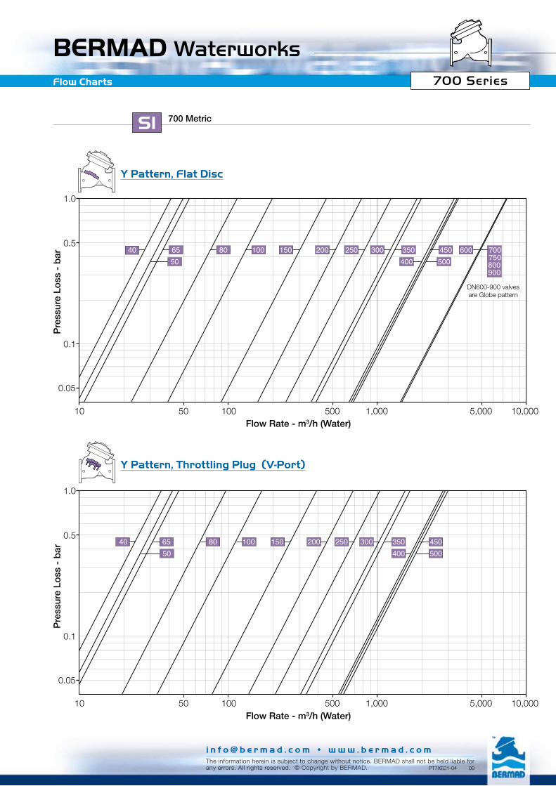
0.1
1.0
10 100 1,000 10,000
0.5
50 500 5,000
0.05
0.1
1.0
10 100 1,000 10,000
0.5
50 500 5,000
0.05
100 125 150 200 250 300 400 5004050
6580
Flow Charts
Pre
ssur
e Lo
ss -
bar
Pre
ssur
e Lo
ss -
bar
Flow Rate - m3/h (Water)
Flow Rate - m3/h (Water)
"Y" Pattern, Throttling Plug (V-Port)
700-ES MetricSI
"Y" Pattern, Flat Disc
i n f o @ b e r m a d . c o m • w w w . b e r m a d . c o mThe information herein is subject to change without notice. BERMAD shall not be held liable forany errors. All rights reserved. © Copyright by BERMAD. PT7XE01-ES 09
BERMAD Waterworks
0.05
0.1
1.0
10 100 1,000 10,000
0.5
50 500 5,000
50040 65
5080 100 150 200 250 300 350 450
400
500100 150 200 250 300 350 450 600 700
750800900
4006550
8040
0.1
1.0
10 100 1,000 10,000
0.5
50 500 5,000
0.05
Flow Charts
Pre
ssur
e Lo
ss -
bar
Pre
ssur
e Lo
ss -
bar
Flow Rate - m3/h (Water)
Flow Rate - m3/h (Water)
700 MetricSI
DN600-900 valves are Globe pattern
700 Series
Y Pattern, Throttling Plug (V-Port)
Y Pattern, Flat Disc
i n f o @ b e r m a d . c o m • w w w . b e r m a d . c o mThe information herein is subject to change without notice. BERMAD shall not be held liable forany errors. All rights reserved. © Copyright by BERMAD. PT7XE01-04 09

i n f o @ b e r m a d . c o m • w w w . b e r m a d . c o mThe information herein is subject to change without notice. BERMAD shall not be held liable forany errors. All rights reserved. © Copyright by BERMAD.
BERMAD WaterworksFlow Charts
PT7XE01-11 09
0.05
6550
80 100 150 200 250 300 350 450400
40
0.1
1.0
10 100 1,000 10,000
0.5
50 500 5,000
0.05
0.1
1.0
10 100 1,000 10,000
0.5
50 500 5,000
6550
250 300 350 450400
40 80 100 150 200
Pre
ssur
e Lo
ss -
bar
Pre
ssur
e Lo
ss -
bar
Flow Rate - m3/h (Water)
Flow Rate - m3/h (Water)
700 MetricSI
700 Series
Angle Pattern, Throttling Plug (V-Port)
Angle Pattern, Flat Disc
BERMAD WaterworksFlow Properties
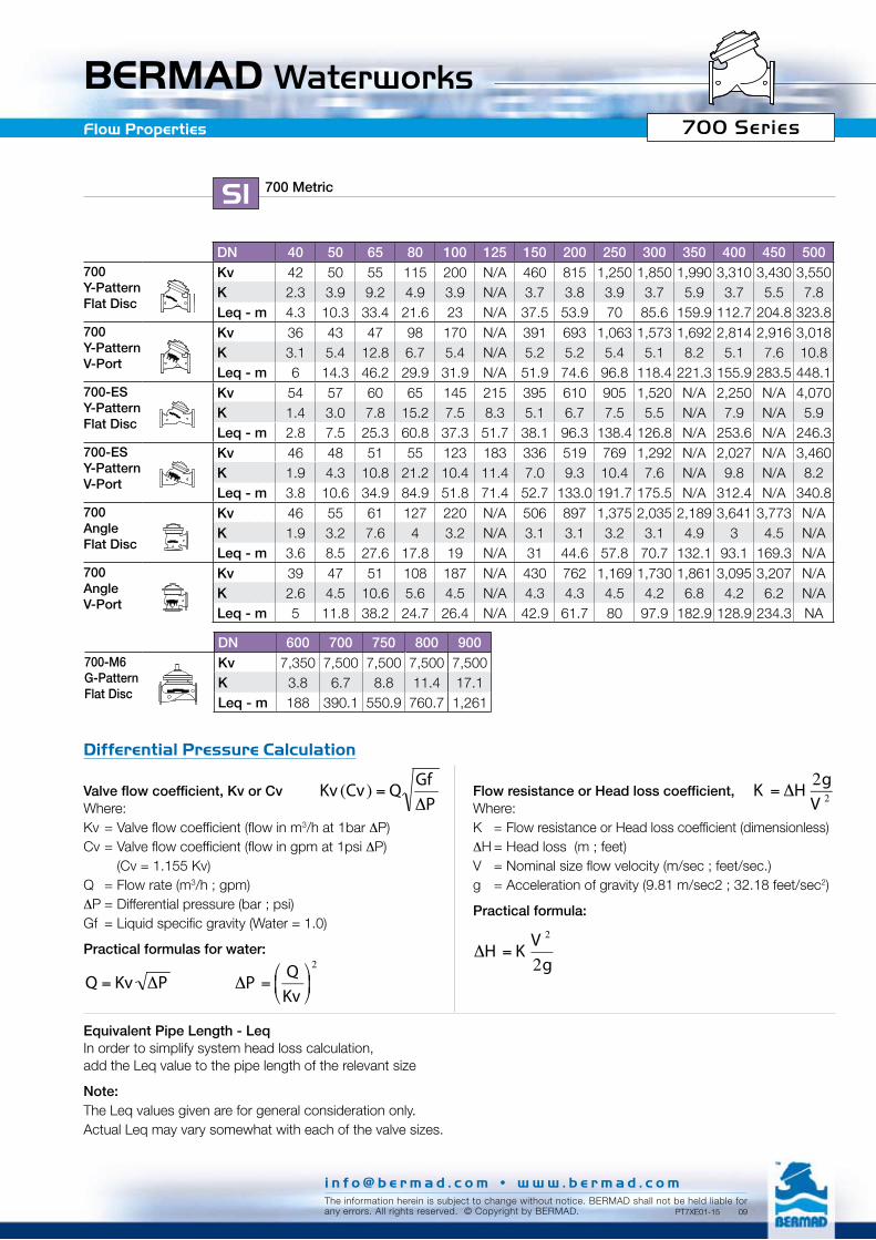
DN 40 50 65 80 100 125 150 200 250 300 350 400 450 500700 Y-PatternFlat Disc
Kv 42 50 55 115 200 N/A 460 815 1,250 1,850 1,990 3,310 3,430 3,550K 2.3 3.9 9.2 4.9 3.9 N/A 3.7 3.8 3.9 3.7 5.9 3.7 5.5 7.8Leq - m 4.3 10.3 33.4 21.6 23 N/A 37.5 53.9 70 85.6 159.9 112.7 204.8 323.8
700Y-PatternV-Port
Kv 36 43 47 98 170 N/A 391 693 1,063 1,573 1,692 2,814 2,916 3,018K 3.1 5.4 12.8 6.7 5.4 N/A 5.2 5.2 5.4 5.1 8.2 5.1 7.6 10.8Leq - m 6 14.3 46.2 29.9 31.9 N/A 51.9 74.6 96.8 118.4 221.3 155.9 283.5 448.1
700-ESY-PatternFlat Disc
Kv 54 57 60 65 145 215 395 610 905 1,520 N/A 2,250 N/A 4,070K 1.4 3.0 7.8 15.2 7.5 8.3 5.1 6.7 7.5 5.5 N/A 7.9 N/A 5.9Leq - m 2.8 7.5 25.3 60.8 37.3 51.7 38.1 96.3 138.4 126.8 N/A 253.6 N/A 246.3
700-ESY-PatternV-Port
Kv 46 48 51 55 123 183 336 519 769 1,292 N/A 2,027 N/A 3,460K 1.9 4.3 10.8 21.2 10.4 11.4 7.0 9.3 10.4 7.6 N/A 9.8 N/A 8.2Leq - m 3.8 10.6 34.9 84.9 51.8 71.4 52.7 133.0 191.7 175.5 N/A 312.4 N/A 340.8
700Angle Flat Disc
Kv 46 55 61 127 220 N/A 506 897 1,375 2,035 2,189 3,641 3,773 N/AK 1.9 3.2 7.6 4 3.2 N/A 3.1 3.1 3.2 3.1 4.9 3 4.5 N/ALeq - m 3.6 8.5 27.6 17.8 19 N/A 31 44.6 57.8 70.7 132.1 93.1 169.3 N/A
700AngleV-Port
Kv 39 47 51 108 187 N/A 430 762 1,169 1,730 1,861 3,095 3,207 N/AK 2.6 4.5 10.6 5.6 4.5 N/A 4.3 4.3 4.5 4.2 6.8 4.2 6.2 N/ALeq - m 5 11.8 38.2 24.7 26.4 N/A 42.9 61.7 80 97.9 182.9 128.9 234.3 NA
700 MetricSI
DN 600 700 750 800 900700-M6G-PatternFlat Disc
Kv 7,350 7,500 7,500 7,500 7,500K 3.8 6.7 8.8 11.4 17.1Leq - m 188 390.1 550.9 760.7 1,261
Valve flow coefficient, Kv or CvWhere:Kv = Valve flow coefficient (flow in m3/h at 1bar ∆P)Cv = Valve flow coefficient (flow in gpm at 1psi ∆P) (Cv = 1.155 Kv)Q = Flow rate (m3/h ; gpm)∆P = Differential pressure (bar ; psi) Gf = Liquid specific gravity (Water = 1.0)
Practical formulas for water:
Flow resistance or Head loss coefficient, Where:K = Flow resistance or Head loss coefficient (dimensionless)∆H = Head loss (m ; feet)V = Nominal size flow velocity (m/sec ; feet/sec.)g = Acceleration of gravity (9.81 m/sec2 ; 32.18 feet/sec2)
Practical formula:
€
∆P =QKv
⎛ ⎝ ⎜
⎞ ⎠ ⎟
2
€
Q = Kv ∆P
€
∆H = KV 2
2g
€
Kv (Cv) = QGf∆P
Equivalent Pipe Length - LeqIn order to simplify system head loss calculation, add the Leq value to the pipe length of the relevant size
Note:The Leq values given are for general consideration only.Actual Leq may vary somewhat with each of the valve sizes.
€
K = ∆H2gV 2
Differential Pressure Calculation
700 Series
i n f o @ b e r m a d . c o m • w w w . b e r m a d . c o mThe information herein is subject to change without notice. BERMAD shall not be held liable forany errors. All rights reserved. © Copyright by BERMAD. PT7XE01-15 09

BERMAD WaterworksCavitation
Cavitation
The cavitation phenomenon has a significant affect on control valve and system performance.Cavitation may damage the valve and piping by the affects of erosion and vibration. Cavitation also generates noise and may limit and ultimately choke the flow. As the pressure differential across the valve increases, the static pressure of the flow passing through the throttling area of the valve (Vena Contracta) drops sharply. When the fluid’s static pressure reaches liquid vapor pressure, vapor cavities (bubbles) form and grow until they violently implode by the recovered pressure downstream to the valve seat. The implosion of these cavities generates high-pressure surges, micro jets and intensive heat, which erode valve components and downstream piping. In its final stage, cavitation flashes and chokes the flow.The above Cavitation Guides for Bermad 700 Series valves are based on the formula commonly used in the valve industry: σ = (P2-Pv) / (P1-P2)
Where:σ = Sigma, cavitation index, dimensionless P1 = Upstream pressure, absoluteP2 = Downstream pressure, absolutePv = Liquid vapor pressure, absolute (Water, 18ºC = 0.02 bar-a ; 65ºF = 0.3 psi-a)
Use these guides and your applications upstream and downstream pressures to determine whether their intersection lies in or out of the cavitation damage zone.Considerations to avoid cavitation damage:A) Reduce system pressure in stages designing each
pressure stage to be above cavitation conditions.B) Consider using other valve selection criteria a. Valve body and plug type b. Valve size c. Valve material
Notes:1. An alternate cavitation index formula introduced by
ISA is: σISA = (P1-Pv) / (P1-P2) which equals σ+1
2. The above charts should be considered only as a general guide.
3. For optimum system and control valve application please consult Bermad.
Cavitation Guide
8
7
6
5
4
3
2
1
00 2 4 6 8 10 12 14 16 18 20 22 24
8
7
6
5
4
3
2
1
00 2 4 6 8 10 12 14 16 18 20 22 24
Do
wns
trea
m p
ress
ure
- b
ar
Do
wns
trea
m p
ress
ure
- b
ar
Upstream pressure - barUpstream pressure - bar
700
/ 700
-EN
700-ES
Cavitation Damage Zone
Cavitation Damage Zone
MetricSI
700 Series
i n f o @ b e r m a d . c o m • w w w . b e r m a d . c o mThe information herein is subject to change without notice. BERMAD shall not be held liable forany errors. All rights reserved. © Copyright by BERMAD. PT7XE01-13 09
BERMAD WaterworksTechnical Specifications 700 Series
i n f o @ b e r m a d . c o m • w w w . b e r m a d . c o mThe information herein is subject to change without notice. BERMAD shall not be held liable forany errors. All rights reserved. © Copyright by BERMAD.
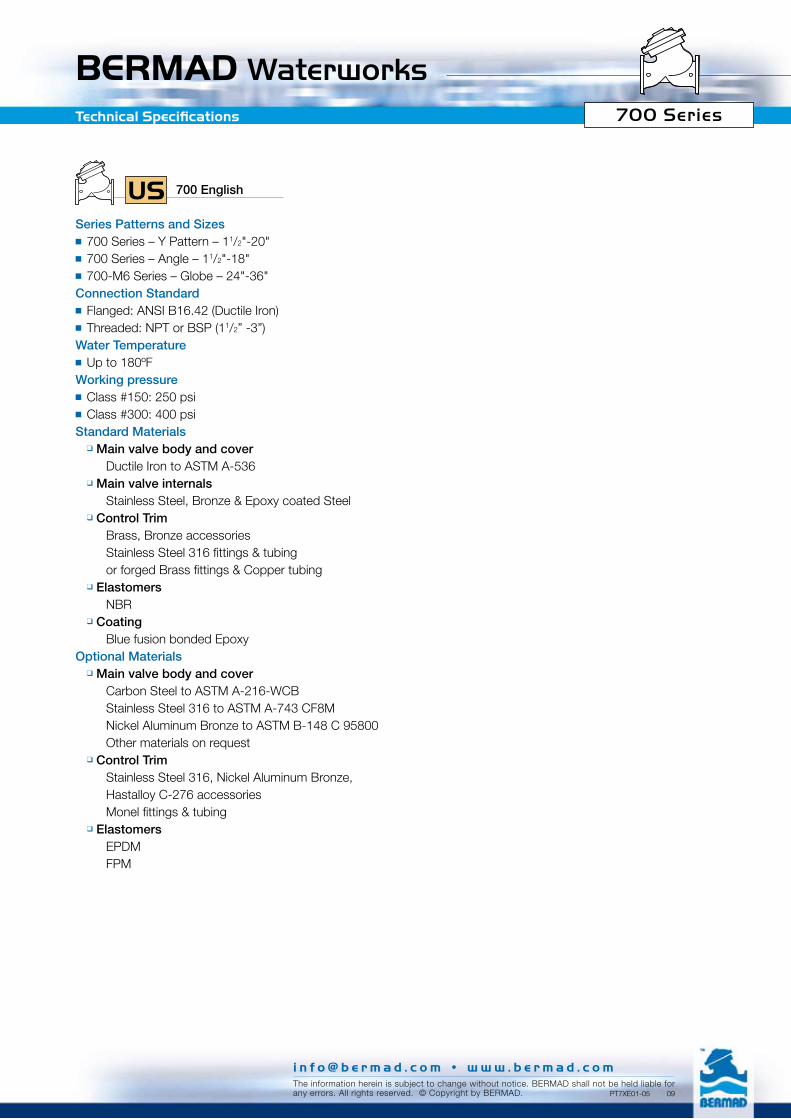
700 EnglishUSSeries Patterns and Sizes ■ 700 Series – Y Pattern – 11/2"-20" ■ 700 Series – Angle – 11/2"-18"■ 700-M6 Series – Globe – 24"-36"Connection Standard■ Flanged: ANSI B16.42 (Ductile Iron)■ Threaded: NPT or BSP (11/2” -3”)Water Temperature■ Up to 180ºFWorking pressure■ Class #150: 250 psi■ Class #300: 400 psi Standard Materials
q Main valve body and cover Ductile Iron to ASTM A-536
q Main valve internals Stainless Steel, Bronze & Epoxy coated Steel
q Control Trim Brass, Bronze accessories Stainless Steel 316 fittings & tubing or forged Brass fittings & Copper tubing
q Elastomers NBR
q Coating Blue fusion bonded Epoxy Optional Materials
q Main valve body and cover Carbon Steel to ASTM A-216-WCB Stainless Steel 316 to ASTM A-743 CF8M Nickel Aluminum Bronze to ASTM B-148 C 95800 Other materials on request
q Control Trim Stainless Steel 316, Nickel Aluminum Bronze, Hastalloy C-276 accessories Monel fittings & tubing
q Elastomers EPDM FPM
PT7XE01-05 09

BERMAD Waterworks700 SeriesDimensions & Weights
Globe Pattern inch 24” 28” 30” 32” 36”
H
h
L
W
AN
SI 1
50
L 57 65 70 73 73W 49 49 49 49 49h 18.5 19 20.5 21.8 23.6H 77 78 79.3 80.6 82.5
Weight (lb) 7,150 8,140 8,580 9,020 9,350
AN
SI 3
00
L 59 65 70 73 73W 49 49 49 49 49h 18.5 19 20.5 21.8 23.6H 77 78 79.3 80.6 82.5
Weight (lb) 7,700 8,140 8,580 9,020 9,370
Angle Pattern inch 11/2” 2” 21/2” 3” 4” 6” 8” 10” 12” 14” 16” 18”
AN
SI 1
50
L 4.9 4.9 5.9 6 7.5 8.9 10.4 12.6 15.6 15.7 17.7 17.7W 6.1 6.1 7 7.9 8.7 12.6 15.4 18.9 21.7 21.7 29.1 29.1R 3.1 3.3 3.7 3.9 4.5 5.6 6.8 8 9.8 10.4 11.8 12.6h 3.3 3.3 4.3 4 5 6 8 8.6 10.7 11 14.5 14.5H 8.9 8.9 9.9 11.1 13.5 17.4 21.5 24.9 30.6 30.7 42.6 42.6
Weight (lb) 21 22 27 47 77 157 260 452 772 816 1,764 1,808
AN
SI 3
00
L 4.9 4.9 5.9 6.3 7.9 9.2 10.9 13.2 16.3 16.5 18.4 18.4W 6.5 6.5 7.3 8.1 9.8 12.6 15.4 18.9 21.7 21.7 29.1 29.1R 3.1 3.3 3.7 4.1 5 6.3 7.5 8.8 10.3 11.5 12.8 14h 3.3 3.3 4.3 4.3 5.3 6.5 8.5 9.3 11.6 11.8 15.2 15.2H 8.9 8.9 9.9 11.3 13.8 17.9 22.0 25.6 31.3 31.5 43.3 43.3
Weight (lb) 24 25 30 51 90 17.9 304 514 860 937 1,885 1,918
W
H
h
LR
Y Pattern inch 11/2” 2” 21/2” 3” 4” 6” 8” 10” 12” 14” 16” 18” 20”A
NS
I 150
L 8.1 8.3 8.7 9.8 12.6 16.3 19.7 23.8 28.5 28.9 39 39.4 43.3W 6.1 6.5 7 7.9 8.8 12.6 15.4 18.9 21.7 21.7 29.1 29.1 29.1h 3.1 3.3 3.7 3.9 4.5 5.6 6.8 8 9.5 10.6 11.8 12.6 14.1H 9.4 9.6 10.1 12 14.4 19.4 23 28.5 33.1 34.1 43.6 44.4 45.9
Weight (lb) 20 23 29 49 82 165 276 478 816 840 1,865 2,083 2,121
AN
SI 3
00
L 8.1 8.3 8.7 10.4 13.2 17 20.6 25.1 30 30.2 40.3 40.6 44.7W 6.1 6.5 7.3 8.1 9.8 12.6 15.4 18.9 21.7 22.4 29.1 29.1 29.5h 3.1 3.3 3.7 4.1 5 6.3 7.5 8.8 10.3 11.6 12.8 14.1 15.3H 9.4 9.6 10.1 12.4 14.9 20 23.7 29.2 33.8 35.2 44.6 45.9 47.1
Weight (lb) 22 27 33 55 95 187 322 540 904 957 1,984 2,132 2,174
H
h
L
W
Flanged
Angle Pattern inch 2” 21/2” 3”
BS
P ;
NP
T
L 4.8 5.5 6.3W 4.8 4.8 6.4R 1.6 1.9 2.2h 3.3 4 4.5H 8.9 9.5 11.6
Weight (lb) 12 15 33
H
LR
h
W
Y Pattern inch 11/2” 2” 21/2” 3”
BS
P ;
NP
T
L 6.1 6.1 8.3 9.8W 4.8 4.8 4.8 6.4
h 1.6 1.6 1.9 2.2H 7.9 8 8.2 10.4
Weight (lb) 12 12 18 37L
W
H
h
Threaded
700 EnglishUS
Control Chamber Displacement Volume (gallon)
Sizes 11/2”-21/2” 3” 4” 6” 8” 10” 12”-14” 16”-20” 24”-36”700 Series 0.04 0.08 0.12 0.57 1.19 2.25 3.28 7.88 25.9800 Series 0.01 0.03 0.08 0.29 0.61 1.06 2.12 4.95 -
i n f o @ b e r m a d . c o m • w w w . b e r m a d . c o mThe information herein is subject to change without notice. BERMAD shall not be held liable forany errors. All rights reserved. © Copyright by BERMAD. PT7XE01-09 09
BERMAD Waterworks
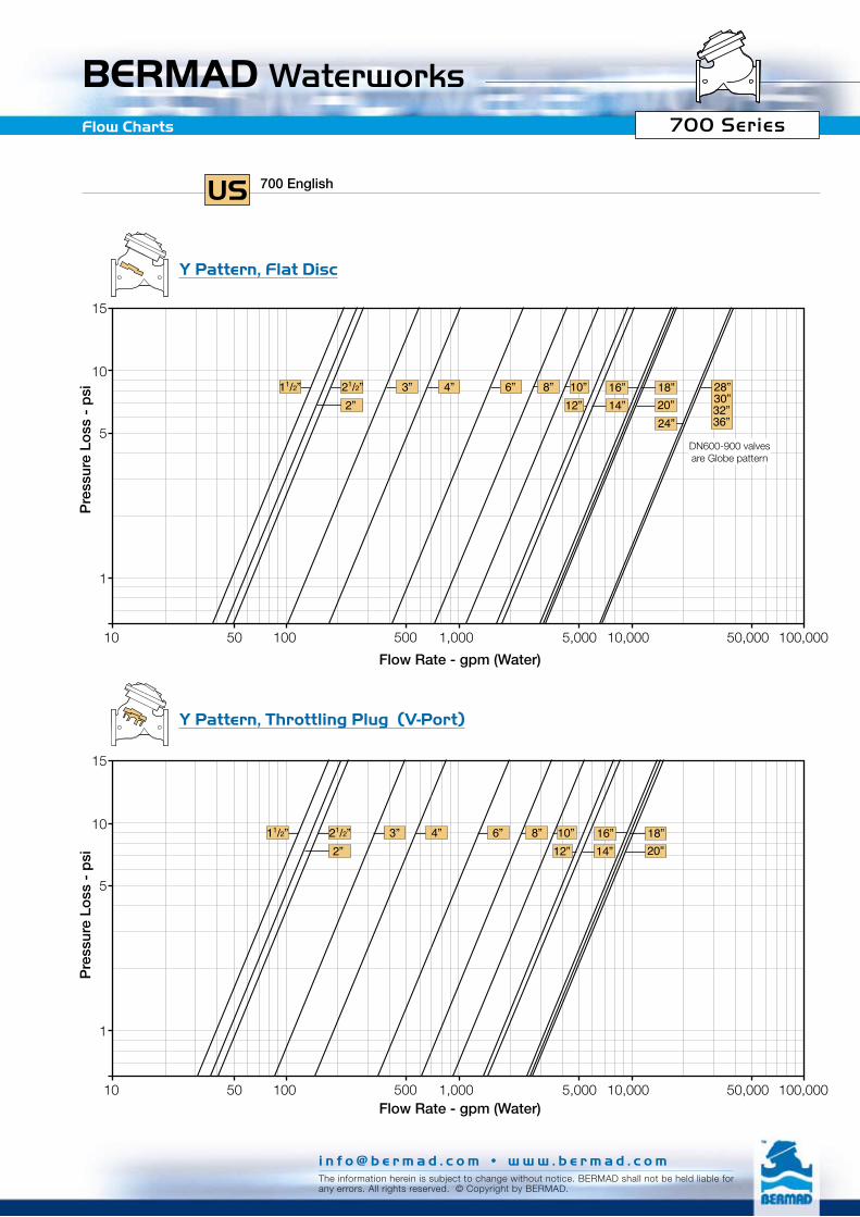
1
10
15
5
10 100 1,000 10,000 100,00050 500 5,000 50,000
3” 4” 6” 8” 18”12”
11/2”2”
21/2”14”16”
20”10”
1
10
15
5
10 100 1,000 10,000 100,00050 500 5,000 50,000
10”
24”
3” 4” 6” 8” 18”12”
11/2”2”
21/2”14”16”
20”28”30”32”36”
Flow Charts
700 EnglishUS
Pre
ssur
e Lo
ss -
psi
Pre
ssur
e Lo
ss -
psi
Flow Rate - gpm (Water)
Flow Rate - gpm (Water)
DN600-900 valves are Globe pattern
700 Series
Y Pattern, Throttling Plug (V-Port)
Y Pattern, Flat Disc
i n f o @ b e r m a d . c o m • w w w . b e r m a d . c o mThe information herein is subject to change without notice. BERMAD shall not be held liable forany errors. All rights reserved. © Copyright by BERMAD.

i n f o @ b e r m a d . c o m • w w w . b e r m a d . c o mThe information herein is subject to change without notice. BERMAD shall not be held liable forany errors. All rights reserved. © Copyright by BERMAD. PT7XE01-12 09
BERMAD Waterworks
1
10
15
5
10 100 1,000 10,000 100,00050 500 5,000 50,000
12”3” 4” 6” 8” 18”11/2”
2”21/2”
14”16”10”
1
10
15
5
10 100 1,000 10,000 100,00050 500 5,000 50,000
3” 4” 6” 8” 18”12”
11/2”2”
21/2”14”16”10”
Flow Charts
700 EnglishUS
Pre
ssur
e Lo
ss -
psi
Pre
ssur
e Lo
ss -
psi
Flow Rate - gpm (Water)
Flow Rate - gpm (Water)
700 Series
Angle Pattern, Flat Disc
Angle Pattern, Throttling Plug (V-Port)
BERMAD WaterworksFlow Properties
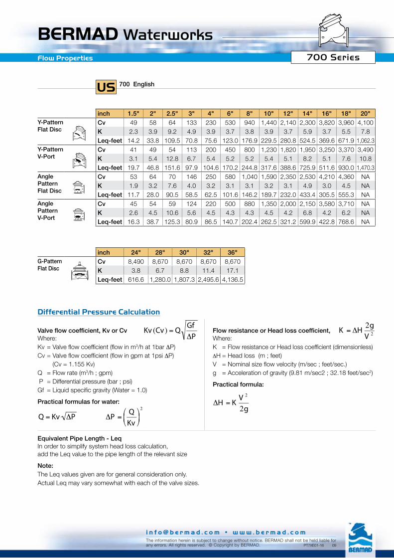
inch 1.5" 2" 2.5" 3" 4" 6" 8" 10" 12" 14" 16" 18" 20"Y-PatternFlat Disc
Cv 49 58 64 133 230 530 940 1,440 2,140 2,300 3,820 3,960 4,100K 2.3 3.9 9.2 4.9 3.9 3.7 3.8 3.9 3.7 5.9 3.7 5.5 7.8Leq-feet 14.2 33.8 109.5 70.8 75.6 123.0 176.9 229.5 280.8 524.5 369.6 671.9 1,062.3
Y-PatternV-Port
Cv 41 49 54 113 200 450 800 1,230 1,820 1,950 3,250 3,370 3,490K 3.1 5.4 12.8 6.7 5.4 5.2 5.2 5.4 5.1 8.2 5.1 7.6 10.8Leq-feet 19.7 46.8 151.6 97.9 104.6 170.2 244.8 317.6 388.6 725.9 511.6 930.0 1,470.3
Angle PatternFlat Disc
Cv 53 64 70 146 250 580 1,040 1,590 2,350 2,530 4,210 4,360 NAK 1.9 3.2 7.6 4.0 3.2 3.1 3.1 3.2 3.1 4.9 3.0 4.5 NALeq-feet 11.7 28.0 90.5 58.5 62.5 101.6 146.2 189.7 232.0 433.4 305.5 555.3 NA
Angle PatternV-Port
Cv 45 54 59 124 220 500 880 1,350 2,000 2,150 3,580 3,710 NAK 2.6 4.5 10.6 5.6 4.5 4.3 4.3 4.5 4.2 6.8 4.2 6.2 NALeq-feet 16.3 38.7 125.3 80.9 86.5 140.7 202.4 262.5 321.2 599.9 422.8 768.6 NA
inch 24" 28" 30" 32" 36"G-PatternFlat Disc
Cv 8,490 8,670 8,670 8,670 8,670K 3.8 6.7 8.8 11.4 17.1Leq-feet 616.6 1,280.0 1,807.3 2,495.6 4,136.5
700 EnglishUS
Valve flow coefficient, Kv or CvWhere:Kv = Valve flow coefficient (flow in m3/h at 1bar ∆P)Cv = Valve flow coefficient (flow in gpm at 1psi ∆P) (Cv = 1.155 Kv)Q = Flow rate (m3/h ; gpm)∆P = Differential pressure (bar ; psi) Gf = Liquid specific gravity (Water = 1.0)
Practical formulas for water:
Flow resistance or Head loss coefficient, Where:K = Flow resistance or Head loss coefficient (dimensionless)∆H = Head loss (m ; feet)V = Nominal size flow velocity (m/sec ; feet/sec.)g = Acceleration of gravity (9.81 m/sec2 ; 32.18 feet/sec2)
Practical formula:
€
∆P =QKv
⎛ ⎝ ⎜
⎞ ⎠ ⎟
2
€
Q = Kv ∆P
€
∆H = KV 2
2g
€
Kv (Cv) = QGf∆P
Equivalent Pipe Length - LeqIn order to simplify system head loss calculation, add the Leq value to the pipe length of the relevant size
Note:The Leq values given are for general consideration only.Actual Leq may vary somewhat with each of the valve sizes.
€
K = ∆H2gV 2
Differential Pressure Calculation
700 Series
i n f o @ b e r m a d . c o m • w w w . b e r m a d . c o mThe information herein is subject to change without notice. BERMAD shall not be held liable forany errors. All rights reserved. © Copyright by BERMAD. PT7XE01-16 09

BERMAD WaterworksCavitation
Cavitation
The cavitation phenomenon has a significant affect on control valve and system performance.Cavitation may damage the valve and piping by the affects of erosion and vibration. Cavitation also generates noise and may limit and ultimately choke the flow. As the pressure differential across the valve increases, the static pressure of the flow passing through the throttling area of the valve (Vena Contracta) drops sharply. When the fluid’s static pressure reaches liquid vapor pressure, vapor cavities (bubbles) form and grow until they violently implode by the recovered pressure downstream to the valve seat. The implosion of these cavities generates high-pressure surges, micro jets and intensive heat, which erode valve components and downstream piping. In its final stage, cavitation flashes and chokes the flow.The above Cavitation Guide for Bermad 700 Series valves are based on the formula commonly used in the valve industry: σ = (P2-Pv) / (P1-P2)
Where:σ = Sigma, cavitation index, dimensionless P1 = Upstream pressure, absoluteP2 = Downstream pressure, absolutePv = Liquid vapor pressure, absolute (Water, 18ºC = 0.02 bar-a ; 65ºF = 0.3 psi-a)
Use these guide and your applications upstream and downstream pressures to determine whether their intersection lies in or out of the cavitation damage zone.Considerations to avoid cavitation damage:A) Reduce system pressure in stages designing each
pressure stage to be above cavitation conditions.B) Consider using other valve selection criteria a. Valve body and plug type b. Valve size c. Valve material
Notes:1. An alternate cavitation index formula introduced by
ISA is: σISA = (P1-Pv) / (P1-P2) which equals σ+1
2. The above charts should be considered only as a general guide.
3. For optimum system and control valve application please consult Bermad.
120
100
80
60
40
30
20
10
0
110
90
70
50
0 30 60 90 120 150 180 210 240 270 300 330 360
Cavitation Guide
Do
wns
trea
m p
ress
ure
- p
si
Upstream pressure - psi
Flat Disc
V-Port Plug
Cavitation Damage Zone
EnglishUS
700 Series
i n f o @ b e r m a d . c o m • w w w . b e r m a d . c o mThe information herein is subject to change without notice. BERMAD shall not be held liable forany errors. All rights reserved. © Copyright by BERMAD. PT7XE01-14 09

BERMAD Waterworks700 Series700 Valve - Exploded View
For spare parts ordering, please use BERMAD “Spare Parts Ordering Guide.”
Lifting eye nut
Cover bolt & disc
Indicator nut
Shaft
Separating partition
Lifting eye bolt
Cover nut & disc
Stud
Spring
O-ring
Seal disc
Seal disc nut
Seal
Seal disc screws
Seat screw
Nut & disc
Valve body
Control hub
Drain
Cover plug
O-ring
Cover
Shaft nut
Diaphragm washerSpacer disc
Diaphragm
Diaphragm washer
Bearing screw
O-ring Bearing disc
Bearing
O-rings
Shaft locking screw
Seal disc washer
V-Port throttling plug - option
Seat
Control hub
i n f o @ b e r m a d . c o m • w w w . b e r m a d . c o mThe information herein is subject to change without notice. BERMAD shall not be held liable forany errors. All rights reserved. © Copyright by BERMAD. PT7XE01-04 09

BERMAD WaterworksPressure Rating
Standard Operation Pressure – Materials DataEnd Connections Standards / Pressure Ratings / Materials / Max. Operating Pressure
BermadCode
End Connections
Standard
Pressure Class
Ductile Iron to ASTM A-536 or EN 1563
Carbon Steel to ASTM A-216-WCB
or EN 10083-1
Stainless Steel 316 to ASTM A-743 CF8M
or EN 10088-1
Nickel Aluminum Bronze to
ASTM B-148 C 95800or BS-EN 1400 AB-2
10 or E1 I S O PN 10 + + + +
16 or E6 I S O PN 16 + + + 16 bar
25 or E5 I S O PN 25 25 bar 25 bar 25 bar 25 bar
40 I S O PN 40 * – 40 bar 40 bar –
A5 A N S I # 150 250 psi 285 psi 285 psi 250 psi
A3 A N S I # 300 400 psi 400 psi 400 psi 400 psi
A4 A N S I # 400 * – 600 psi 600 psi –
BD BS 10 Table D + + + +
BH BS 10 Table H 400 psi 400 psi 400 psi 400 psi
J1 J I S 10 K + + + +
J6 J I S 16 K 27 bar 27 bar 27 bar 27 bar
J2 J I S 20 K 28 bar 28 bar 28 bar 28 bar
J3 J I S 30 K * – 40 bar 40 bar –
B1 A B N T 10 + + + +
B6 A B N T 16 + + + 16 bar
B2 A B N T 25 25 bar 25 bar 25 bar 25 bar
Threads
BP B S P (Rp ISO 7/1)
PH B S P (Rp ISO 7/1) 25 bar 25 bar 25 bar 25 bar
NP N P T
NH N P T 400 psi 400 psi 400 psi 400 psi
External flange diameter might vary from the standard.* Can be used in 800 series only.+ Available, Not required by the standard pressure class– Not available
700 Series
i n f o @ b e r m a d . c o m • w w w . b e r m a d . c o mThe information herein is subject to change without notice. BERMAD shall not be held liable forany errors. All rights reserved. © Copyright by BERMAD. PT7XE01-03 09

BERMAD Waterworks
Valve Plugs CharacteristicsKv ; Cv to Valve Opening Chart
Typical Pressure Reducing Performance ChartActual Hydraulic Laboratory Results
0
10
20
30
40
50
60
70
80
90
100
0 10 20 30 40 50 60 70 80 90 100
15
14
13
12
11
10
9
8
7
6
5
4
3
2
1
00 100 200 300 400 500 600 700 800 900 1,000 1,100 1,200
700
600
500
400
300
200
100
0
V-Port Plug
Flat Disc
Valv
e Tr
avel
%
Kv ; Cv %
Pre
ssur
e -
bar
Flo
w -
m3 /
h
Upstream Pressure
Flow Rate
Downstream Pressure
Time - sec
700 Series
i n f o @ b e r m a d . c o m • w w w . b e r m a d . c o mThe information herein is subject to change without notice. BERMAD shall not be held liable forany errors. All rights reserved. © Copyright by BERMAD. PT7XE01-17 09
Top Related