


Languages
Pages
Legal

Reference numberISO 606:2004(E)
© ISO 2004
INTERNATIONAL STANDARD
ISO606
Third edition2004-03-15
Short-pitch transmission precision roller and bush chains, attachments and associated chain sprockets
Chaînes de transmission de précision à rouleaux et à douilles, plaques-attaches et roues dentées correspondantes

ISO 606:2004(E)
PDF disclaimer This PDF file may contain embedded typefaces. In accordance with Adobe's licensing policy, this file may be printed or viewed but shall not be edited unless the typefaces which are embedded are licensed to and installed on the computer performing the editing. In downloading this file, parties accept therein the responsibility of not infringing Adobe's licensing policy. The ISO Central Secretariat accepts no liability in this area.
Adobe is a trademark of Adobe Systems Incorporated.
Details of the software products used to create this PDF file can be found in the General Info relative to the file; the PDF-creation parameters were optimized for printing. Every care has been taken to ensure that the file is suitable for use by ISO member bodies. In the unlikely event that a problem relating to it is found, please inform the Central Secretariat at the address given below.
© ISO 2004 All rights reserved. Unless otherwise specified, no part of this publication may be reproduced or utilized in any form or by any means, electronic or mechanical, including photocopying and microfilm, without permission in writing from either ISO at the address below or ISO's member body in the country of the requester.
ISO copyright office Case postale 56 • CH-1211 Geneva 20 Tel. + 41 22 749 01 11 Fax + 41 22 749 09 47 E-mail [email protected] Web www.iso.org
Published in Switzerland
ii © ISO 2004 – All rights reserved

ISO 606:2004(E)
© ISO 2004 – All rights reserved iii
Contents Page
Foreword............................................................................................................................................................ iv Introduction ........................................................................................................................................................ v 1 Scope...................................................................................................................................................... 1 2 Normative references ........................................................................................................................... 1 3 Chains .................................................................................................................................................... 1 4 Attachments ........................................................................................................................................ 11 5 Chain sprockets .................................................................................................................................. 15 Annex A (normative) Pitch-circle diameters.................................................................................................. 22 Annex B (informative) Equivalent chain designations ................................................................................. 24 Annex C (informative) Method of calculating chain minimum dynamic strength...................................... 25 Annex D (informative) Method of determining maximum test force Fmax when conducting dynamic
strength conformance test................................................................................................................. 27 Bibliography ..................................................................................................................................................... 28

ISO 606:2004(E)
iv © ISO 2004 – All rights reserved
Foreword
ISO (the International Organization for Standardization) is a worldwide federation of national standards bodies (ISO member bodies). The work of preparing International Standards is normally carried out through ISO technical committees. Each member body interested in a subject for which a technical committee has been established has the right to be represented on that committee. International organizations, governmental and non-governmental, in liaison with ISO, also take part in the work. ISO collaborates closely with the International Electrotechnical Commission (IEC) on all matters of electrotechnical standardization.
International Standards are drafted in accordance with the rules given in the ISO/IEC Directives, Part 2.
The main task of technical committees is to prepare International Standards. Draft International Standards adopted by the technical committees are circulated to the member bodies for voting. Publication as an International Standard requires approval by at least 75 % of the member bodies casting a vote.
Attention is drawn to the possibility that some of the elements of this document may be the subject of patent rights. ISO shall not be held responsible for identifying any or all such patent rights.
ISO 606 was prepared by Technical Committee ISO/TC 100, Chains and chain wheels for power transmission and conveyors.
This third edition cancels and replaces the second edition (ISO 606:1994) and ISO 1395:1977, of which it constitutes a technical revision.
ISO 606:2004(E)
© ISO 2004 – All rights reserved v
Introduction
The provisions of this revised International Standard have been established by including sizes of chains used by the majority of countries in the world, and by unifying dimensions, strengths and other data which differed in current national standards, while eliminating those for which it was considered a universal usage had not been established.
The whole field of application open to this medium of transmission has been covered by the ranges of chains already established. To achieve this, the sizes of 6,35 mm pitch to 76,2 mm pitch inclusive have been duplicated, on the one hand, by the inclusion of chains derived from standards originating and centred around ANSI (denoted by suffix A), and on the other by chains representing the unification of the principal standards originating in Europe (suffix B), the two being complementary for the coverage of the widest possible field of application.
The ANSI chain reference numbers (25, 35, 40, 50, etc.) are used world-wide and, to assist in cross-referencing the ISO and ANSI numbers, details are now included in Annex C of this International Standard.
The ANSI heavy series of chains (suffix H) are also included. The ANSI heavy series of chains differ from the ANSI standard series in that thicker plates are used. As there are no existing ISO numbers for these chains, the ANSI numbering system has been adopted.
Clause 4 covers specification details for K and M attachments, and extended pin attachments for use with short-pitch transmission roller and bush chains conforming with this International Standard.
Clause 5, covering chain sprockets, represents the unification of all the relevant national standards in the world and includes, in particular, complete tolerances relating to tooth form.
The inclusion of the dimensions of the chains specified ensures complete interchangeability of any given size and provides interchangeability of individual links of chains.
This edition also includes short-pitch bush transmission chains previously covered in ISO 1395:1977.

INTERNATIONAL STANDARD ISO 606:2004(E)
© ISO 2004 – All rights reserved 1
Short-pitch transmission precision roller and bush chains, attachments and associated chain sprockets
1 Scope
This International Standard specifies the characteristics of short-pitch precision roller and bush chains with associated sprockets suitable for the mechanical transmission of power and allied applications. It covers dimensions, tolerances, length measurement, preloading, minimum tensile strengths and minimum dynamic strength.
Although Clause 5 applies to chain sprockets for cycles and motor cycles, this International Standard is not applicable to their chains, which are covered by ISO 9633 and ISO 10190, respectively.
2 Normative references
The following referenced documents are indispensable for the application of this document. For dated references, only the edition cited applies. For undated references, the latest edition of the referenced document (including any amendments) applies.
ISO 286-2:1988, ISO system of limits and fits — Part 2: Tables of standard tolerance grades and limit deviations for holes and shafts
ISO 15654, Fatigue test method for transmission precision roller chains 1)
3 Chains
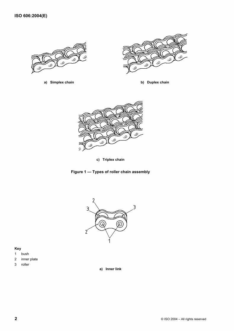
3.1 Nomenclature of assemblies and components
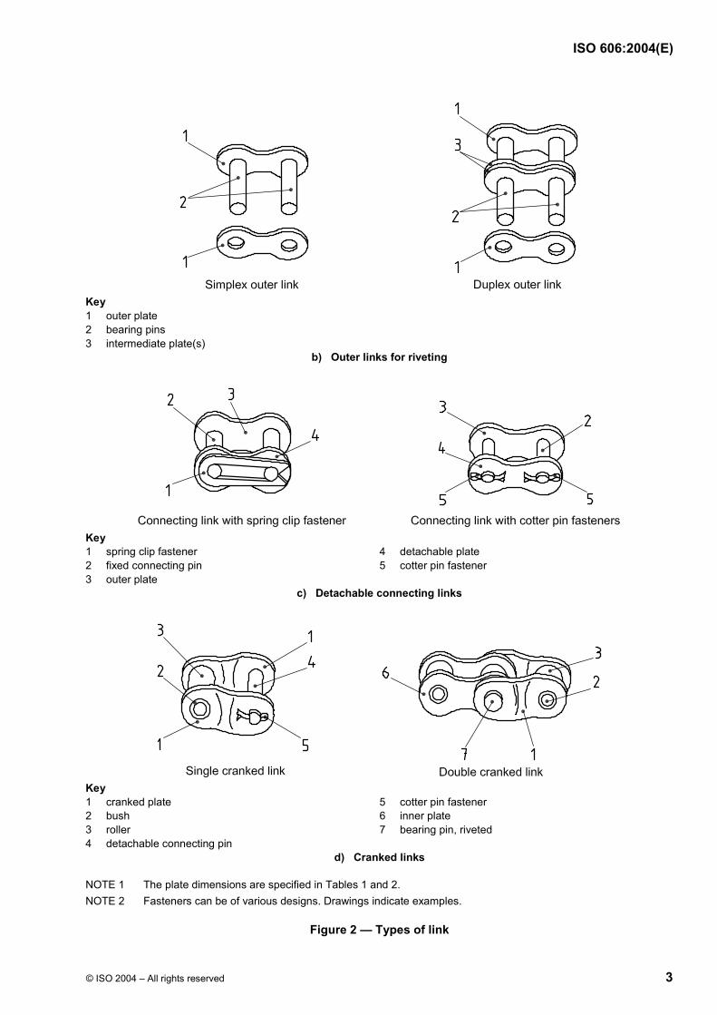
The nomenclature of chain assemblies and their component parts is shown in Figures 1 and 2 (which do not define the actual form of the chain plates).
1) To be published.
ISO 606:2004(E)
2 © ISO 2004 – All rights reserved
a) Simplex chain b) Duplex chain
c) Triplex chain
Figure 1 — Types of roller chain assembly
Key 1 bush 2 inner plate 3 roller
a) Inner link
ISO 606:2004(E)
© ISO 2004 – All rights reserved 3
Key 1 outer plate 2 bearing pins 3 intermediate plate(s)
b) Outer links for riveting
Key 1 spring clip fastener 4 detachable plate 2 fixed connecting pin 5 cotter pin fastener 3 outer plate
c) Detachable connecting links
Key 1 cranked plate 5 cotter pin fastener 2 bush 6 inner plate 3 roller 7 bearing pin, riveted 4 detachable connecting pin
d) Cranked links
NOTE 1 The plate dimensions are specified in Tables 1 and 2. NOTE 2 Fasteners can be of various designs. Drawings indicate examples.
Figure 2 — Types of link

ISO 606:2004(E)
4 © ISO 2004 – All rights reserved
3.2 Designation
Chains are designated by the standard ISO chain number given in Tables 1 and 2. The ISO chain numbers in Table 1 are supplemented by a hyphenated suffix 1 for simplex chain, 2 for duplex chain and 3 for triplex chain, for example, 16B-1, 16B-2, 16B-3. Chains 081, 083, 084 and 085 do not follow this procedure since they are normally available in simplex form only.
The chains designated in Table 2 are the ANSI heavy series, which are also supplemented by a hyphenated suffix 1 for simplex chain, 2 for duplex chain and 3 for triplex chain, for example, 80H-1, 80H-2, 80H-3.
3.3 Dimensions
Chains shall conform to the dimensions shown in Figure 3 and given in Tables 1 and 2. Maximum and minimum dimensions are specified to ensure interchangeability of links produced by different makers of chain. They represent limits for interchangeability, but are not the manufacturing tolerances.
Key c clearance between cranked link plates and straight plates available during articulation p pitch
1 outer plate 2 cranked plate 3 inner plate
NOTE For the symbols, see Table 1.
a) Cranked link

ISO 606:2004(E)
© ISO 2004 – All rights reserved 5
NOTE For the symbols, see Table 1.
a Clearance between the cranked link plates and the straight plates available during articulation.
b) Sections through chain
NOTE For the symbols, see Table 1.
c) Types of chain
Figure 3 — Chains

ISO 606:2004(E)
6 © ISO 2004 – All rights reserved
The overall width of a simplex, duplex or triplex chain with a joint fastener is given by
a) for riveted pin end chains if the fastener is on one side only:
(b4 + b7) or (b5 + b7) or (b6 + b7);
b) for riveted pin end chains if the fastener is on two sides:
[b4 + (2b7)] or [b5 + (2b7)] or [b6 + (2b7)];
c) for headed pin end chains if the fastener is on one side only:
[b4 + (1,6b7)] or [b5 + (1,6b7)] or [b6 + (1,6b7)];
d) for headed pin end chains if the fastener is on two sides:
[b4 + (3,2b7)] or [b5 + (3,2b7)] or [b6 + (3,2b7)];
The overall width of chains wider than triplex is given by
b4 + [pt × (number of strands in chain − 1)].
3.4 Performance requirements
3.4.1 General
WARNING — The test requirements are not to be taken as working loads. These loads could be selected, indirectly, using ISO 10823. The test results shall be invalid if the chain has previously been in service or stressed in any way (other than by preloading in accordance with 3.4.3).
The tests given in 3.4.2 to 3.4.5 shall only be performed on unused, undamaged chain to determine whether the subject chain complies with the minimum requirements specified in Tables 1 and 2.
3.4.2 Tensile testing
3.4.2.1 The minimum tensile strength is that value which shall be exceeded when a tensile force is applied to a sample tested to destruction in accordance with 3.4.2.2.
NOTE This minimum tensile strength is not a working load, but is intended primarily as a comparative figure between chains of various constructions.
3.4.2.2 Apply a tensile force slowly to the ends of a chain length containing at least five free pitches by means of fixtures permitting free movement on both sides of the chain centreline, in the normal plane of articulation.
Failure shall be considered to have occurred at the first point where increasing extension is no longer accompanied by increasing force, i.e. the summit of the force/extension diagram. The force at this point shall exceed the minimum tensile strength stated in Tables 1 and 2.
Tests in which failures occur adjacent to the shackles shall be disregarded.
3.4.2.3 The tensile test shall be considered as a destructive test. Even though a chain may not visibly fail when subjected to a force equivalent to the minimum tensile strength, it will have been stressed beyond the yield point and will be unfit for service.
3.4.2.4 These requirements do not apply to cranked links, connecting links or chains with attachments, as their tensile strength could be reduced.

ISO 606:2004(E)
© ISO 2004 – All rights reserved 7
3.4.3 Preloading
Chains manufactured in conformance with this International Standard shall be preloaded by applying a minimum tensile force equivalent to 30 % of the minimum tensile strength given in Tables 1 and 2.
3.4.4 Length validation
Measurement of chains shall take place after preloading but before lubrication.
The standard length for measurement shall be a minimum of
a) 610 mm for ISO chain numbers 04C to 12B and 081 to 085 inclusive, or
b) 1 220 mm for ISO chain numbers 16A to 72B inclusive.
The chain shall be supported throughout its entire length and the measuring force specified in Tables 1 and 2 shall be applied.
The measured length shall be the nominal length 0,15 %0
+ except for chains with attachments, when it shall be the nominal length 0,30 %
0+ .
The length accuracy of chains which have to work in parallel may be matched within closer tolerances.
3.4.5 Dynamic testing
Chains in conformance with this International Standard shall survive a conformance test, as specified in ISO 15654, using the dynamic strength values given in Tables 1 or 2 for the particular chain. These requirements do not apply to cranked links, connecting links or chains with attachments, as their dynamic strength could be reduced. The methods used for calculating the minimum dynamic strength are given in Annex C. The method for determining the maximum test force for the conformance test is given in Annex D.
3.5 Marking
The chain shall be marked with the manufacturer's name or trademark. The chain number quoted in Tables 1 or 2 should be marked on the chain.
3.6 Cranked links
Cranked links should not be used with the heavy series chains or on chains which are intended for highly stressed applications. Where a cranked link is used a reduction in performance will occur.

ISO 606:2004(E)
8 © ISO 2004 – All rights reserved
Tabl
e 1
— P
rinci
pal c
hain
dim
ensi
ons,
mea
surin
g fo
rces
, ten
sile
str
engt
hs a
nd d
ynam
ic s
tren
gth
valu
es (s
ee F
igur
es 1
and
3)
Max
imum
wid
th o
ver
bear
ing
pins
M
easu
ring
forc
e M
inim
um te
nsile
stre
ngth
ISO Chain number a
Pitch
Maximum roller diameter
Minimum width between inner plates
Maximum bearing pin body diameter
Minimum bush bore
Minimum chain path depth
Maximum inner plate depth
Maximum outer or intermediate plate depth
Min
imum
cra
nked
lin
k di
men
sion
s b
Transverse pitch
Maximum width over inner link
Minimum width between outer plates
Cha
in
Maximum additional width for joint fastener c
Cha
in
Cha
in
Minimum dynamic strength Simplex d, e, f
Sim
plex
Dup
lex
Trip
lex
Si
mpl
exD
uple
x Tr
iple
x Si
mpl
exD
uple
x Tr
iple
x
p d 1
b 1
d 2
d 3
h 1
h 2
h 3
l 1
l 2
c
p t
b 2
b 3
b 4
b 5
b 6
b 7
F u
F d
mm
N
kN
N
04C
6,35
3,
30 g
3,10
2,
31
2,34
6,
27
6,02
5,
21
2,65
3,
08
0,10
6,40
4,
80
4,85
9,
1 15
,5
21,8
2,
5 50
10
0 15
0 3,
5 7,
0 10
,5
630
06C
9,52
5 5,
08 g
4,68
3,
60
3,62
9,
30
9,05
7,
81
3,97
4,
60
0,10
10,1
3 7,
46
7,52
13
,2
23,4
33
,5
3,3
70
140
210
7,9
15,8
23
,7
1410
05
B 8,
00
5,00
3,
00
2,31
2,
36
7,37
7,
11
7,11
3,
71
3,71
0,
085,
64
4,77
4,
90
8,6
14,3
19
,9
3,1
50
100
150
4,4
7,8
11,1
82
0 06
B 9,
525
6,35
5,
72
3,28
3,
33
8,52
8,
26
8,26
4,
32
4,32
0,
0810
,24
8,53
8,
66
13,5
23
,8
34,0
3,
3 70
14
0 21
0 8,
9 16
,9
24,9
1
290
08A
12,7
0 7,
92
7,85
3,
98
4,00
12
,33
12,0
7 10
,42
5,29
6,
10
0,08
14,3
8 11
,17
11,2
3 17
,8
32,3
46
,7
3,9
120
250
370
13,9
27
,8
41,7
2
480
08B
12,7
0 8,
51
7,75
4,
45
4,50
12
,07
11,8
1 10
,92
5,66
6,
12
0,08
13,9
2 11
,30
11,4
3 17
,0
31,0
44
,9
3,9
120
250
370
17,8
31
,1
44,5
2
480
081
12,7
0 7,
75
3,30
3,
66
3,71
10
,17
9,91
9,
91
5,36
5,
36
0,08
—
5,80
5,
93
10,2
—
—
1,
5 12
5 —
—
8,
0 —
—
—
08
3 12
,70
7,75
4,
88
4,09
4,
14
10,5
6 10
,30
10,3
0 5,
36
5,36
0,
08—
7,
90
8,03
12
,9
—
—
1,5
125
—
—
11,6
—
—
—
08
4 12
,70
7,75
4,
88
4,09
4,
14
11,4
1 11
,15
11,1
5 5,
77
5,77
0,
08—
8,
80
8,93
14
,8
—
—
1,5
125
—
—
15,6
—
—
—
08
5 12
,70
7,77
6,
25
3,60
3,
62
10,1
7 9,
91
8,51
4,
35
5,03
0,
08—
9,
06
9,12
14
,0
—
—
2,0
80
—
—
6,7
—
—
1 34
0
10
A 15
,875
10
,16
9,40
5,
09
5,12
15
,35
15,0
9 13
,02
6,61
7,
62
0,10
18,1
1 13
,84
13,8
9 21
,8
39,9
57
,9
4,1
200
390
590
21,8
43
,6
65,4
3
850
10B
15,8
75
10,1
6 9,
65
5,08
5,
13
14,9
9 14
,73
13,7
2 7,
11
7,62
0,
1016
,59
13,2
8 13
,41
19,6
36
,2
52,8
4,
1 20
0 39
0 59
0 22
,2
44,5
66
,7
3 33
0 12
A 19
,05
11,9
1 12
,57
5,96
5,
98
18,3
4 18
,10
15,6
2 7,
90
9,15
0,
1022
,78
17,7
5 17
,81
26,9
49
,8
72,6
4,
6 28
0 56
0 84
0 31
,3
62,6
93
,9
5 49
0 12
B 19
,05
12,0
7 11
,68
5,72
5,
77
16,3
9 16
,13
16,1
3 8,
33
8,33
0,
1019
,46
15,6
2 15
,75
22,7
42
,2
61,7
4,
6 28
0 56
0 84
0 28
,9
57,8
86
,7
3 72
0
16
A 25
,40
15,8
8 15
,75
7,94
7,
96
24,3
9 24
,13
20,8
3 10
,55
12,2
00,
1329
,29
22,6
0 22
,66
33,5
62
,7
91,9
5,
4 50
0 1
000
1 49
0 55
,6
111,
2 16
6,8
9 55
0 16
B 25
,40
15,8
8 17
,02
8,28
8,
33
21,3
4 21
,08
21,0
8 11
,15
11,1
50,
1331
,88
25,4
5 25
,58
36,1
68
0 99
,9
5,4
500
1 00
0 1
490
60,0
10
6,0
160,
0 9
530
20A
31,7
5 19
,05
18,9
09,
54
9,56
30
,48
30,1
7 26
,04
13,1
615
,24
0,15
35,7
6 27
,45
27,5
1 41
,1
77,0
11
3,0
6,1
780
1 56
0 2
340
87,0
17
4,0
261,
0 14
600
20
B 31
,75
19,0
5 19
,56
10,1
910
,24
26,6
8 26
,42
26,4
2 13
,89
13,8
90,
1536
,45
29,0
1 29
,14
43,2
79
,7
116,
1 6,
1 78
0 1
560
2 34
0 95
,0
170,
0 25
0,0
13 5
00
24A
38,1
0 22
,23
25,2
211
,11
11,1
4 36
,55
36,2
31
,24
15,8
018
,27
0,18
45,4
4 35
,45
35,5
1 50
,8
96,3
14
1,7
6,6
1 11
0 2
220
3 34
0 12
5,0
250,
0 37
5,0
20 5
00
24B
38,1
0 25
,40
25,4
014
,63
14,6
8 33
,73
33,4
33
,40
17,5
517
,55
0,18
48,3
6 37
,92
38,0
5 53
,4
101,
8 15
0,2
6,6
1 11
0 2
220
3 34
0 16
0,0
280,
0 42
5,0
19 7
00
28A
44,4
5 25
,40
25,2
212
,71
12,7
4 42
,67
42,2
3 36
,45
18,4
221
,32
0,20
48,8
7 37
,18
37,2
4 54
,9
103,
6 15
2,4
7,4
1 51
0 3
020
4 54
0 17
0,0
340,
0 51
0,0
27 3
00
ISO 606:2004(E)
© ISO 2004 – All rights reserved 9
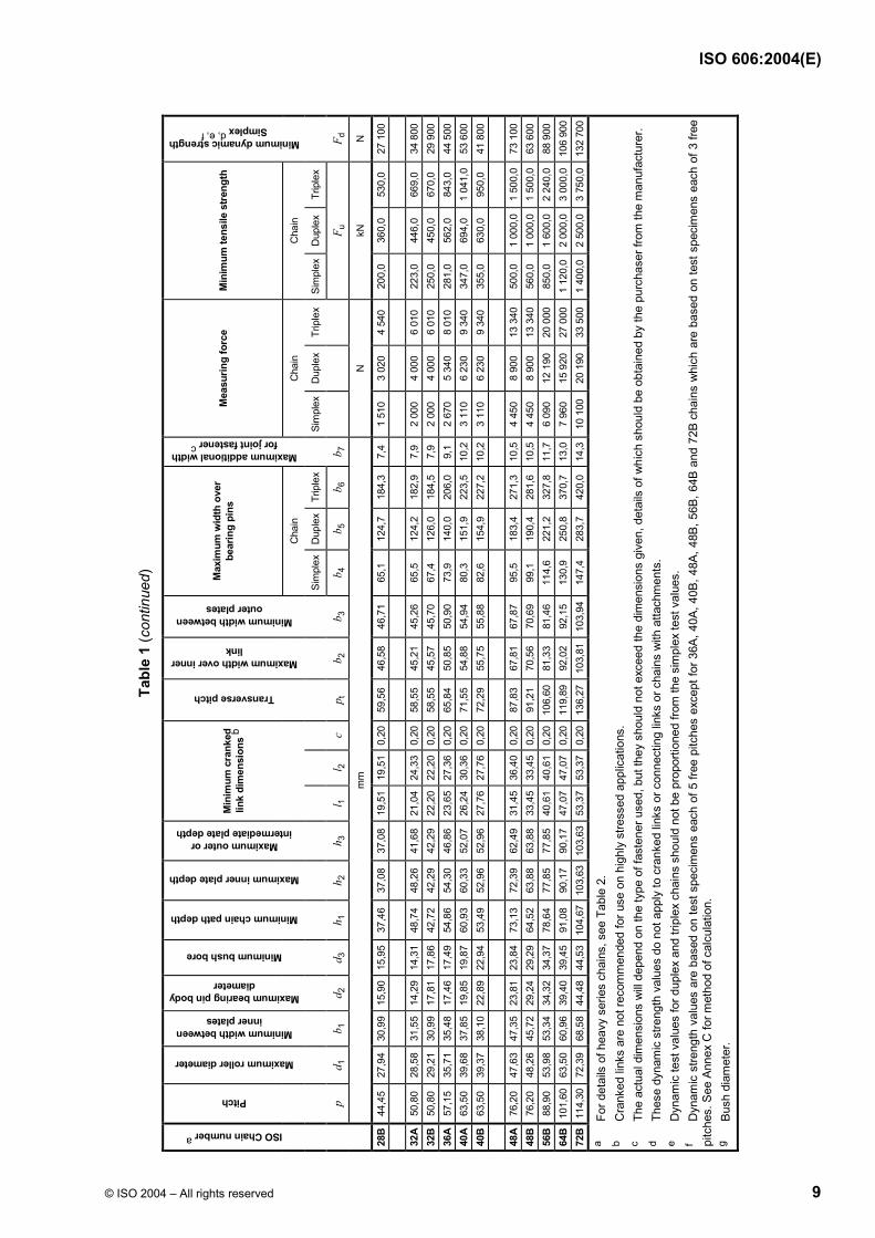
Tabl
e 1
(con
tinue
d)
Max
imum
wid
th o
ver
bear
ing
pins
M
easu
ring
forc
e M
inim
um te
nsile
stre
ngth
ISO Chain number a
Pitch
Maximum roller diameter
Minimum width between inner plates
Maximum bearing pin body diameter
Minimum bush bore
Minimum chain path depth
Maximum inner plate depth
Maximum outer or intermediate plate depth
Min
imum
cra
nked
lin
k di
men
sion
s b
Transverse pitch
Maximum width over inner link
Minimum width between outer plates
Cha
in
Maximum additional width for joint fastener c
Cha
in
Cha
in
Minimum dynamic strength Simplex d, e, f
Sim
plex
Dup
lex
Trip
lex
Si
mpl
exD
uple
x Tr
iple
x Si
mpl
exD
uple
x Tr
iple
x
p d 1
b 1
d 2
d 3
h 1
h 2
h 3
l 1
l 2
c
p t
b 2
b 3
b 4
b 5
b 6
b 7
F u
F d
mm
N
kN
N
28B
44,4
5 27
,94
30,9
915
,90
15,9
5 37
,46
37,0
8 37
,08
19,5
119
,51
0,20
59,5
6 46
,58
46,7
1 65
,1
124,
7 18
4,3
7,4
1 51
0 3
020
4 54
0 20
0,0
360,
0 53
0,0
27 1
00
32A
50,8
0 28
,58
31,5
514
,29
14,3
1 48
,74
48,2
6 41
,68
21,0
424
,33
0,20
58,5
5 45
,21
45,2
6 65
,5
124,
2 18
2,9
7,9
2 00
0 4
000
6 01
0 22
3,0
446,
0 66
9,0
34 8
00
32B
50,8
0 29
,21
30,9
917
,81
17,8
6 42
,72
42,2
9 42
,29
22,2
022
,20
0,20
58,5
5 45
,57
45,7
0 67
,4
126,
0 18
4,5
7,9
2 00
0 4
000
6 01
0 25
0,0
450,
0 67
0,0
29 9
00
36A
57,1
5 35
,71
35,4
817
,46
17,4
9 54
,86
54,3
0 46
,86
23,6
527
,36
0,20
65,8
4 50
,85
50,9
0 73
,9
140,
0 20
6,0
9,1
2 67
0 5
340
8 01
0 28
1,0
562,
0 84
3,0
44 5
00
40A
63,5
0 39
,68
37,8
519
,85
19,8
7 60
,93
60,3
3 52
,07
26,2
430
,36
0,20
71,5
5 54
,88
54,9
4 80
,3
151,
9 22
3,5
10,2
3 11
0 6
230
9 34
0 34
7,0
694,
0 1
041,
0 53
600
40
B 63
,50
39,3
7 38
,10
22,8
922
,94
53,4
9 52
,96
52,9
6 27
,76
27,7
60,
2072
,29
55,7
5 55
,88
82,6
15
4,9
227,
2 10
,23
110
6 23
0 9
340
355,
0 63
0,0
950,
0 41
800
48
A 76
,20
47,6
3 47
,35
23,8
123
,84
73,1
3 72
,39
62,4
9 31
,45
36,4
00,
2087
,83
67,8
1 67
,87
95,5
18
3,4
271,
3 10
,54
450
8 90
0 13
340
50
0,0
1 00
0,0
1 50
0,0
73 1
00
48B
76,2
0 48
,26
45,7
229
,24
29,2
9 64
,52
63,8
8 63
,88
33,4
533
,45
0,20
91,2
1 70
,56
70,6
9 99
,1
190,
4 28
1,6
10,5
4 45
0 8
900
13 3
40
560,
0 1
000,
0 1
500,
0 63
600
56
B 88
,90
53,9
8 53
,34
34,3
234
,37
78,6
4 77
,85
77,8
5 40
,61
40,6
10,
2010
6,60
81,3
3 81
,46
114,
6 22
1,2
327,
8 11
,76
090
12 1
90
20 0
00
850,
0 1
600,
0 2
240,
0 88
900
64
B 10
1,60
63
,50
60,9
639
,40
39,4
5 91
,08
90,1
7 90
,17
47,0
747
,07
0,20
119,
8992
,02
92,1
5 13
0,9
250,
8 37
0,7
13,0
7 96
0 15
920
27
000
1
120,
0 2
000,
0 3
000,
0 10
6 90
0 72
B 11
4,30
72
,39
68,5
844
,48
44,5
3 10
4,67
10
3,63
10
3,63
53,3
753
,37
0,20
136,
2710
3,81
103,
9414
7,4
283,
7 42
0,0
14,3
10 1
00
20 1
90
33 5
00
1 40
0,0
2 50
0,0
3 75
0,0
132
700
a Fo
r det
ails
of h
eavy
ser
ies
chai
ns, s
ee T
able
2.
b C
rank
ed li
nks
are
not r
ecom
men
ded
for u
se o
n hi
ghly
stre
ssed
app
licat
ions
. c
The
actu
al d
imen
sion
s w
ill de
pend
on
the
type
of f
aste
ner u
sed,
but
they
sho
uld
not e
xcee
d th
e di
men
sion
s gi
ven,
det
ails
of w
hich
sho
uld
be o
btai
ned
by th
e pu
rcha
ser f
rom
the
man
ufac
ture
r. d
Thes
e dy
nam
ic s
treng
th v
alue
s do
not
app
ly to
cra
nked
link
s or
con
nect
ing
links
or c
hain
s w
ith a
ttach
men
ts.
e D
ynam
ic te
st v
alue
s fo
r dup
lex
and
tripl
ex c
hain
s sh
ould
not
be
prop
ortio
ned
from
the
sim
plex
test
val
ues.
f
Dyn
amic
stre
ngth
val
ues
are
base
d on
test
spe
cim
ens
each
of 5
free
pitc
hes
exce
pt fo
r 36A
, 40A
, 40B
, 48A
, 48B
, 56B
, 64B
and
72B
cha
ins
whi
ch a
re b
ased
on
test
spe
cim
ens
each
of 3
free
pi
tche
s. S
ee A
nnex
C fo
r met
hod
of c
alcu
latio
n.
g Bu
sh d
iam
eter
.
ISO 606:2004(E)
10 © ISO 2004 – All rights reserved
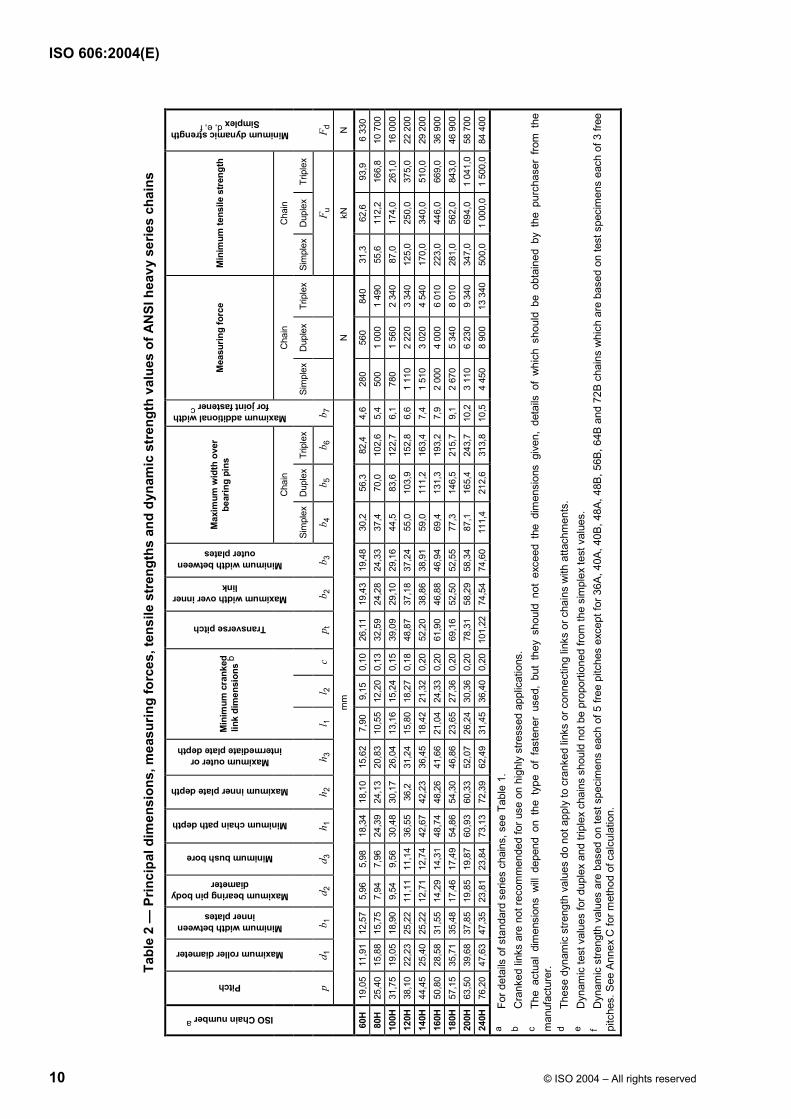
Tabl
e 2
— P
rinci
pal d
imen
sion
s, m
easu
ring
forc
es, t
ensi
le s
tren
gths
and
dyn
amic
str
engt
h va
lues
of A
NSI
hea
vy s
erie
s ch
ains
Max
imum
wid
th o
ver
bear
ing
pins
M
easu
ring
forc
e M
inim
um te
nsile
stre
ngth
ISO Chain number a
Pitch
Maximum roller diameter
Minimum width between inner plates
Maximum bearing pin body diameter
Minimum bush bore
Minimum chain path depth
Maximum inner plate depth
Maximum outer or intermediate plate depth
Min
imum
cra
nked
lin
k di
men
sion
s b
Transverse pitch
Maximum width over inner link
Minimum width between outer plates
Cha
in
Maximum additional width for joint fastener c
Cha
in
Cha
in
Minimum dynamic strength Simplex d, e, f
Sim
plex
Dup
lex
Trip
lex
Si
mpl
exD
uple
x Tr
iple
x Si
mpl
exD
uple
x Tr
iple
x
p d 1
b 1
d 2
d 3
h 1
h 2
h 3
l 1
l 2
c
p t
b 2
b 3
b 4
b 5
b 6
b 7
F u
F d
mm
N
kN
N
60H
19,0
5 11
,91
12,5
75,
96
5,98
18
,34
18,1
0 15
,62
7,90
9,
15
0,10
26,1
1 19
,43
19,4
8 30
,2
56,3
82
,4
4,6
280
560
840
31,3
62
,6
93,9
6
330
80H
25,4
0 15
,88
15,7
57,
94
7,96
24
,39
24,1
3 20
,83
10,5
512
,20
0,13
32,5
9 24
,28
24,3
3 37
,4
70,0
10
2,6
5,4
500
1 00
0 1
490
55,6
11
2,2
166,
8 10
700
10
0H
31,7
5 19
,05
18,9
09,
54
9,56
30
,48
30,1
7 26
,04
13,1
615
,24
0,15
39,0
9 29
,10
29,1
6 44
,5
83,6
12
2,7
6,1
780
1 56
0 2
340
87,0
17
4,0
261,
0 16
000
12
0H
38,1
0 22
,23
25,2
211
,11
11,1
4 36
,55
36,2
31
,24
15,8
018
,27
0,18
48,8
7 37
,18
37,2
4 55
,0
103,
9 15
2,8
6,6
1 11
0 2
220
3 34
0 12
5,0
250,
0 37
5,0
22 2
00
140H
44
,45
25,4
0 25
,22
12,7
1 12
,74
42,6
7 42
,23
36,4
5 18
,42
21,3
20,
2052
,20
38,8
6 38
,91
59,0
11
1,2
163,
4 7,
4 1
510
3 02
0 4
540
170,
0 34
0,0
510,
0 29
200
16
0H
50,8
0 28
,58
31,5
514
,29
14,3
1 48
,74
48,2
6 41
,66
21,0
424
,33
0,20
61,9
0 46
,88
46,9
4 69
,4
131,
3 19
3,2
7,9
2 00
0 4
000
6 01
0 22
3,0
446,
0 66
9,0
36 9
00
180H
57
,15
35,7
1 35
,48
17,4
6 17
,49
54,8
6 54
,30
46,8
6 23
,65
27,3
60,
2069
,16
52,5
0 52
,55
77,3
14
6,5
215,
7 9,
1 2
670
5 34
0 8
010
281,
0 56
2,0
843,
0 46
900
20
0H
63,5
0 39
,68
37,8
519
,85
19,8
7 60
,93
60,3
3 52
,07
26,2
430
,36
0,20
78,3
1 58
,29
58,3
4 87
,1
165,
4 24
3,7
10,2
3 11
0 6
230
9 34
0 34
7,0
694,
0 1
041,
0 58
700
24
0H
76,2
0 47
,63
47,3
523
,81
23,8
4 73
,13
72,3
9 62
,49
31,4
536
,40
0,20
101,
2274
,54
74,6
0 11
1,4
212,
6 31
3,8
10,5
4 45
0 8
900
13 3
40
500,
0 1
000,
0 1
500,
0 84
400
a Fo
r det
ails
of s
tand
ard
serie
s ch
ains
, see
Tab
le 1
. b
Cra
nked
link
s ar
e no
t rec
omm
ende
d fo
r use
on
high
ly s
tress
ed a
pplic
atio
ns.
c Th
e ac
tual
dim
ensi
ons
will
depe
nd o
n th
e ty
pe o
f fa
sten
er u
sed,
but
the
y sh
ould
not
exc
eed
the
dim
ensi
ons
give
n, d
etai
ls o
f w
hich
sho
uld
be o
btai
ned
by t
he p
urch
aser
fro
m t
he
man
ufac
ture
r. d
Thes
e dy
nam
ic s
treng
th v
alue
s do
not
app
ly to
cra
nked
link
s or
con
nect
ing
links
or c
hain
s w
ith a
ttach
men
ts.
e D
ynam
ic te
st v
alue
s fo
r dup
lex
and
tripl
ex c
hain
s sh
ould
not
be
prop
ortio
ned
from
the
sim
plex
test
val
ues.
f
Dyn
amic
stre
ngth
val
ues
are
base
d on
test
spe
cim
ens
each
of 5
free
pitc
hes
exce
pt fo
r 36A
, 40A
, 40B
, 48A
, 48B
, 56B
, 64B
and
72B
cha
ins
whi
ch a
re b
ased
on
test
spe
cim
ens
each
of 3
free
pi
tche
s. S
ee A
nnex
C fo
r met
hod
of c
alcu
latio
n.

ISO 606:2004(E)
© ISO 2004 – All rights reserved 11
4 Attachments
4.1 Nomenclature
The nomenclature for chain attachments is given in Figures 4, 5, 6 and 7, and in Tables 1, 3, 4 and 5.
NOTE 1 For d4, h4 and f, see Table 3; for p, see Table 1. NOTE 2 K attachment plates can be positioned on either outer or inner links. NOTE 3 K1 plates could be identical to K2 plates except that they have one hole located centrally. NOTE 4 The assembly of K2 plates on adjacent links is not possible.
Figure 4 — K attachment plates
NOTE 1 For d4 and h5, see Table 4; for p, see Table 1. NOTE 2 M attachment plates can be positioned on either outer or inner links. NOTE 3 M1 plates could be identical to M2 plates except that they have one hole located centrally. NOTE 4 The assembly of M2 plates on adjacent links is not recommended.
Figure 5 — M attachment plates
NOTE For b4 and p, see Table 1; for b5, b8 and d2, see Table 5.
Figure 6 — Extended bearing pins (based on duplex pin) — Type X
ISO 606:2004(E)
12 © ISO 2004 – All rights reserved
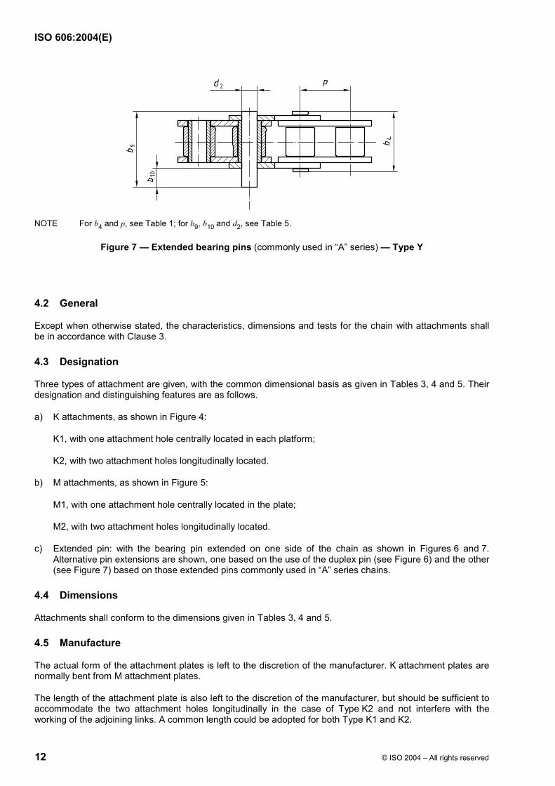
NOTE For b4 and p, see Table 1; for b9, b10 and d2, see Table 5.
Figure 7 — Extended bearing pins (commonly used in “A” series) — Type Y
4.2 General
Except when otherwise stated, the characteristics, dimensions and tests for the chain with attachments shall be in accordance with Clause 3.
4.3 Designation
Three types of attachment are given, with the common dimensional basis as given in Tables 3, 4 and 5. Their designation and distinguishing features are as follows.
a) K attachments, as shown in Figure 4:
K1, with one attachment hole centrally located in each platform;
K2, with two attachment holes longitudinally located.
b) M attachments, as shown in Figure 5:
M1, with one attachment hole centrally located in the plate;
M2, with two attachment holes longitudinally located.
c) Extended pin: with the bearing pin extended on one side of the chain as shown in Figures 6 and 7. Alternative pin extensions are shown, one based on the use of the duplex pin (see Figure 6) and the other (see Figure 7) based on those extended pins commonly used in “A” series chains.
4.4 Dimensions
Attachments shall conform to the dimensions given in Tables 3, 4 and 5.
4.5 Manufacture
The actual form of the attachment plates is left to the discretion of the manufacturer. K attachment plates are normally bent from M attachment plates.
The length of the attachment plate is also left to the discretion of the manufacturer, but should be sufficient to accommodate the two attachment holes longitudinally in the case of Type K2 and not interfere with the working of the adjoining links. A common length could be adopted for both Type K1 and K2.

ISO 606:2004(E)
© ISO 2004 – All rights reserved 13
4.6 Marking
It is not a requirement that K and M attachment plates be marked.
The marking of the extended pin chain shall be the same as that which would be shown on a chain with no attachments (see 3.5).
Table 3 — Attachment plate K — Dimensions (see Figure 4)
Platform height Minimum hole diameter Traverse distance between hole centres
h4 d4 f ISO chain number
mm mm mm
06C 6,4 2,6 19
08A 7,9 3,3 25,4
08B 8,9 4,3 25,4
10A 10,3 5,1 31,8
10B 10,3 5,3 31,8
12A 11,9 5,1 38,1
12B 13,5 6,4 38,1
16A 15,9 6,6 50,8
16B 15,9 6,4 50,8
20A 19,8 8,2 63,5
20B 19,8 8,4 63,5
24A 23 9,8 76,2
24B 26,7 10,5 76,2
28A 28,6 11,4 88,9
28B 28,6 13,1 88,9
32A 31,8 13,1 101,6
32B 31,8 13,1 101,6
40A 42,9 16,3 127

ISO 606:2004(E)
14 © ISO 2004 – All rights reserved
Table 4 — Attachment plate M — Dimensions (see Figure 5)
Height from chain centre line Minimum diameter of holes
h5 d4 ISO chain number
mm mm
06C 9,5 2,6 08A 12,7 3,3 08B 13 4,3 10A 15,9 5,1 10B 16,5 5,3 12A 18,3 5,1 12B 21 6,4 16A 24,6 6,6 16B 23 6,4 20A 31,8 8,2 20B 30,5 8,4 24A 36,5 9,8 24B 36 10,5 28A 44,4 11,4 32A 50,8 13,1 40A 63,5 16,3
Table 5 — Extended pin dimensions (see Figures 6 and 7)
Dimensions in millimetres
Pin extension Pin extension a Pin diameter
Type “X” Type “Y” Types “X” and “Y”
b8 b5 b10 b9 d2
ISO chain number
max. max. max. max. max.
05B 7,1 14,3 — — 2,31 06C 12,3 23,4 10,2 21,9 3,6 06B 12,2 23,8 — — 3,28 08A 16,5 32,3 10,2 26,3 3,98 08B 15,5 31 — — 4,45 10A 20,6 39,9 12,7 32,6 5,09 10B 18,5 36,2 — — 5,08 12A 25,7 49,8 15,2 40 5,96 12B 21,5 42,2 — — 5,72 16A 32,2 62,7 20,3 51,7 7,94 16B 34,5 68 — — 8,28 20A 39,1 77 25,4 63,8 9,54 20B 39,4 79,7 — — 10,19 24A 48,9 96,3 30,5 78,6 11,11 24B 51,4 101,8 — — 14,63 28A — — 35,6 87,5 12,71 32A — — 40,6 102,6 14,29
a The pin extensions of Type “Y” are given as alternatives, as they are commonly used in “A” series chains.
ISO 606:2004(E)
© ISO 2004 – All rights reserved 15
5 Chain sprockets
5.1 General
This clause gives specifications for chain sprockets for use with short-pitch transmission precision roller and bush chains conforming to Clause 3 and specifies general criteria for ensuring correct meshing, operation and transmission of load when used under normal operating conditions.
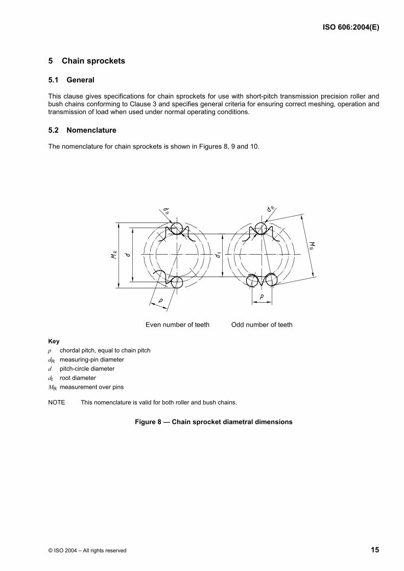
5.2 Nomenclature
The nomenclature for chain sprockets is shown in Figures 8, 9 and 10.
Key p chordal pitch, equal to chain pitch dR measuring-pin diameter d pitch-circle diameter df root diameter MR measurement over pins
NOTE This nomenclature is valid for both roller and bush chains.
Figure 8 — Chain sprocket diametral dimensions
ISO 606:2004(E)
16 © ISO 2004 – All rights reserved
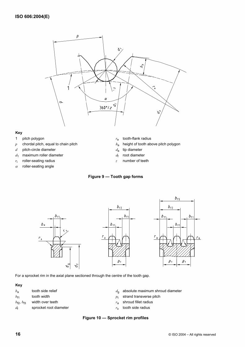
Key 1 pitch polygon re tooth-flank radius p chordal pitch, equal to chain pitch ha height of tooth above pitch polygon d pitch-circle diameter da tip diameter d1 maximum roller diameter df root diameter ri roller-seating radius z number of teeth α roller-seating angle
Figure 9 — Tooth gap forms
For a sprocket rim in the axial plane sectioned through the centre of the tooth gap.
Key ba tooth side relief dg absolute maximum shroud diameter bf1 tooth width pt strand transverse pitch bf2, bf3 width over teeth ra shroud fillet radius df sprocket root diameter rx tooth side radius
Figure 10 — Sprocket rim profiles

ISO 606:2004(E)
© ISO 2004 – All rights reserved 17
5.3 Diametral dimensions of sprocket rim
5.3.1 Nomenclature
See Figure 8.
5.3.2 Dimensions
5.3.2.1 Pitch-circle diameter, d
The chain sprocket pitch-circle diameter, d, is given by
180sin
pd
z
=°
Annex A gives the pitch-circle diameter for unit pitch as a function of the number of teeth.
5.3.2.2 Measuring-pin diameter, dR
The chain sprocket measuring-pin diameter dR is given by
dR = d1
(see Figure 9)
with a tolerance of 0,010
+ mm.
5.3.2.3 Root diameter, df
The chain sprocket root diameter df is given by
df = d − d1
with a tolerance in accordance with Table 6.
Table 6 — Root diameter tolerances Dimensions in millimetres
Root diameter df
Tolerance
df u 127 00,25−
127 < df u 250 00,3−
df > 250 h11 a
a See ISO 286-2.

ISO 606:2004(E)
18 © ISO 2004 – All rights reserved
5.3.2.4 Measurement over pins
For an even number of teeth, the measurement over pins is given by
R R, minM d d= +
For an odd number of teeth, the measurement over pins is given by
R R, min90 cosM d d
z°
= +
The measurement over pins of sprockets with an even number of teeth shall be carried out over pins inserted in opposite tooth gaps.
The measurement over pins of sprockets with an odd number of teeth shall be carried out over pins in the tooth gaps most nearly opposite.
The limits of tolerance for measurement over pins are identical to those for the corresponding root diameters.
5.4 Sprocket tooth gap forms
5.4.1 Nomenclature
See Figure 9.
5.4.2 Dimensions
5.4.2.1 General
The limits of the tooth gap form are determined by the minimum and maximum tooth gap forms. The actual tooth gap form, which is provided by cutting or an equivalent method, shall have tooth flanks of a form lying between the minimum and maximum flank radii and blending smoothly with the roller seating curve subtending the respective angles.
5.4.2.2 Minimum form
The corresponding values for re, ri and α are given by
re,max = 0,12d1 (z + 2)
ri,min = 0,505d1
αmax = 140°− 90z
°
5.4.2.3 Maximum form
The corresponding values for re, ri and α are given by
re,min = 0,008d1 (z2 + 180)
ri,max = 0,505d1 + 0,069 3 1d
αmin = 120° − 90z
°
ISO 606:2004(E)
© ISO 2004 – All rights reserved 19
5.5 Tooth heights and tip diameters
5.5.1 Nomenclature
See Figure 9.
5.5.2 Dimensions
The maximum and minimum values of the tip diameter da are given by
da,max = d + 1,25p − d1
da,min = d + p 11,61 dz
− −
NOTE da,min and da,max can be applied arbitrarily both to the minimum and maximum gap forms, subject to the limitations imposed on the maximum diameter by the cutter.
To facilitate the construction of the tooth gap form to a large scale, the tooth height above the pitch polygon can be obtained from the following formulae:
ha,max = 0,625p − 0,5d1 + 0,8 pz
ha,min = 0,5 (p − d1)
NOTE ha,max is related to da,max and ha,min to da,min.
5.6 Sprocket rim profiles
5.6.1 Nomenclature
See Figure 10.
5.6.2 Dimensions
5.6.2.1 Tooth width
Tooth width dimensions are given by the following.
a) For p u 12,7 mm:
bf1 = 0,93b1 : h14 2) for simplex chain sprockets;
bf1 = 0,91b1 : h14 for duplex and triplex chain sprockets;
bf1 = 0,88b1: h14 for quadruplex chain wheels and above.
b) For p > 12,7 mm:
bf1 = 0,95b1 : h14 for simplex chain sprockets;
bf1 = 0,93b1 : h14 for duplex and triplex chain sprockets.
2) See ISO 286-2.

ISO 606:2004(E)
20 © ISO 2004 – All rights reserved
The formulae given in a) for quadruplex chains and above may be used by agreement between user and manufacturer.
5.6.2.2 Other dimensions
For all chains: bf2 and bf3 = (number of strands − 1) × pt + bf1 (tolerance h14 3) on bf1)
For all chains: x,nomr p=
For chain numbers 081, 083, 084 and 085: a,nom 0,06b p=
For all other chains: a,nom 0,13b p=
For chain numbers 04C and 06C: g 2 a180cot 1,05 1,00 2d p h r
z= − − −
For all other chains: g 2180cot 1,04 (0,76 mm)d p h
z= − −
5.7 Radial run-out
Radial run-out between the bore and root diameter shall not exceed a total indicator reading of greater than the larger of the two following values:
(0,000 8 df + 0,08) mm, or
0,15 mm,
up to a maximum of 0,76 mm.
5.8 Axial run-out (wobble)
Axial run-out, measured with reference to the bore and the flat part of the side face of the teeth, shall not exceed a total indicator reading of
(0,000 9 df + 0,08) mm,
up to a maximum of 1,14 mm.
For fabricated (welded) sprockets, 0,25 mm is acceptable if the above formula gives smaller values.
5.9 Pitch accuracy of sprocket teeth
Pitch accuracy of sprocket teeth is important and chain manufacturers should be consulted for details.
5.10 Number of teeth
This International Standard primarily applies to a number of teeth from 9 to 150 inclusive.
The preferred numbers of teeth are 17, 19, 21, 23, 25, 38, 57, 76, 95 and 114.
5.11 Bore tolerance
Unless otherwise agreed between manufacturer and purchaser, bore tolerance shall be H8 3).
3) See ISO 286-2.

ISO 606:2004(E)
© ISO 2004 – All rights reserved 21
5.12 Marking
Sprockets shall be marked with the following:
a) manufacturer's name or trademark;
b) number of teeth;
c) chain designation (ISO chain number and/or manufacturer's equivalent).

ISO 606:2004(E)
22 © ISO 2004 – All rights reserved
Annex A (normative)
Pitch circle diameters
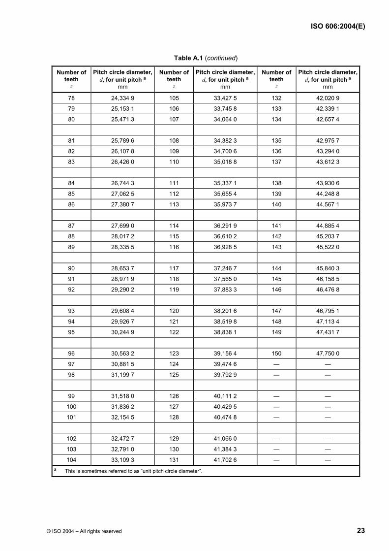
Table A.1 gives the correct pitch circle diameters for sprockets to suit a chain of unit pitch. The pitch circle diameters for sprockets to suit a chain of any other pitch are directly proportional to the pitch of the chain.
Table A.1 — Pitch circle diameters
Number of teeth
z
Pitch circle diameter, d, for unit pitch a
mm
Number of teeth
z
Pitch circle diameter, d, for unit pitch a
mm
Number of teeth
z
Pitch circle diameter, d, for unit pitch a
mm
9 2,923 8 32 10,202 3 55 17,516 6
10 3,236 1 33 10,520 1 56 17,834 7
11 3,549 4 34 10,838 0 57 18,152 9
12 3,863 7 35 11,155 8 58 18,471 0
13 4,178 6 36 11,473 7 59 18,789 2
14 4,494 0 37 11,791 6 60 19,107 3
15 4,809 7 38 12,109 6 61 19,425 5
16 5,125 8 39 12,427 5 62 19,743 7
17 5,442 2 40 12,745 5 63 20,061 9
18 5,758 8 41 13,063 5 64 20,380 0
19 6,075 5 42 13,381 5 65 20,698 2
20 6,392 5 43 13,699 5 66 21,016 4
21 6,709 5 44 14,017 6 67 21,334 6
22 7,026 6 45 14,335 6 68 21,652 8
23 7,343 9 46 14,653 7 69 21,971 0
24 7,661 3 47 14,971 7 70 22,289 2
25 7,978 7 48 15,289 8 71 22,607 4
26 8,296 2 49 15,607 9 72 22,925 6
27 8,613 8 50 15,926 0 73 23,243 8
28 8,931 4 51 16,244 1 74 23,562 0
29 9,249 1 52 16,562 2 75 23,880 2
30 9,566 8 53 16,880 3 76 24,198 5
31 9,884 5 54 17,198 4 77 24,516 7
ISO 606:2004(E)
© ISO 2004 – All rights reserved 23
Table A.1 (continued)
Number of teeth
z
Pitch circle diameter, d, for unit pitch a
mm
Number of teeth
z
Pitch circle diameter, d, for unit pitch a
mm
Number of teeth
z
Pitch circle diameter, d, for unit pitch a
mm
78 24,334 9 105 33,427 5 132 42,020 9
79 25,153 1 106 33,745 8 133 42,339 1
80 25,471 3 107 34,064 0 134 42,657 4
81 25,789 6 108 34,382 3 135 42,975 7
82 26,107 8 109 34,700 6 136 43,294 0
83 26,426 0 110 35,018 8 137 43,612 3
84 26,744 3 111 35,337 1 138 43,930 6
85 27,062 5 112 35,655 4 139 44,248 8
86 27,380 7 113 35,973 7 140 44,567 1
87 27,699 0 114 36,291 9 141 44,885 4
88 28,017 2 115 36,610 2 142 45,203 7
89 28,335 5 116 36,928 5 143 45,522 0
90 28,653 7 117 37,246 7 144 45,840 3
91 28,971 9 118 37,565 0 145 46,158 5
92 29,290 2 119 37,883 3 146 46,476 8
93 29,608 4 120 38,201 6 147 46,795 1
94 29,926 7 121 38,519 8 148 47,113 4
95 30,244 9 122 38,838 1 149 47,431 7
96 30,563 2 123 39,156 4 150 47,750 0
97 30,881 5 124 39,474 6 — —
98 31,199 7 125 39,792 9 — —
99 31,518 0 126 40,111 2 — —
100 31,836 2 127 40,429 5 — —
101 32,154 5 128 40,474 8 — —
102 32,472 7 129 41,066 0 — —
103 32,791 0 130 41,384 3 — —
104 33,109 3 131 41,702 6 — — a This is sometimes referred to as “unit pitch circle diameter”.

ISO 606:2004(E)
24 © ISO 2004 – All rights reserved
Annex B (informative)
Equivalent chain designations
See Table B.1.
Table B.1 — Equivalent chain designations
Chain pitch ISO chain number ANSI chain number
mm
6,35 04C 25
9,525 06C 35
12,7 08A 40
12,7 085 41
15,875 10A 50
19,05 12A 60
25,4 16A 80
31,75 20A 100
38,1 24A 120
44,45 28A 140
50,8 32A 160
57,15 36A 180
63,5 40A 200
76,2 48A 240

ISO 606:2004(E)
© ISO 2004 – All rights reserved 25
Annex C (informative)
Method of calculating chain minimum dynamic strength
C.1 “A” series chain
For 085 chain only: Fd = Ks × Ai × p(− 0,000 8 p).
For all other chains: Fd = Ks × 0,118 × p(2 − 0,000 8 p);
where
Fd is the chain minimum dynamic strength at 3 × 10⁶ cycles, in newtons (N);
Ai is 12,01 mm2 for 085 chain only;
Ks is
115 N/mm2 for 085 chain only,
134 N/mm2 for chains up to and including 32A,
139 N/mm2 for chains 36A and above 4);
p is the chain pitch, in millimetres (mm).
C.2 “A” series heavy chain
( )2 0,000 8d s 0,118 pF K p −= × × ×
0,5i heavy
i standard
bb
where
bi is the estimated inner plate thickness given by
( )2 12,11
b b− mm;
b2 is the maximum width over inner link, in millimetres (mm);
b1 is the minimum width between inner plates, in millimetres (mm);
4) Constant Ks is increased from 134 N/mm2 to 139 N/mm2 to allow for the reduction in the test specimen length from 5 free pitches to 3 free pitches when conducting the dynamic strength test.
ISO 606:2004(E)
26 © ISO 2004 – All rights reserved
Ks is
134 N/mm2 for chains up to and including 160H,
139 N/mm2 for chains 180H and above 5);
p is the chain pitch, in millimetres (mm).
C.3 “B” series chain
Fd = Ks × Ai × p(– 0,000 9p)
where
Ai is the sectional area of inner plate, given by
2bi × (0,99h2 − db) mm2;
bi is the estimated inner plate thickness, given by
( )2 1 mm;2,11
b b−
db is the estimated bush diameter, given by
0,4751
22
mm;ddd
×
b2 is the maximum width over the inner link, in millimetres (mm);
b1 is the minimum width between the inner plates, in millimetres (mm);
d2 is the maximum pin diameter, in millimetres (mm);
d1 is the maximum roller diameter, in millimetres (mm);
h2 is the maximum inner plate depth, in millimetres (mm);
Ks is
134 N/mm2 for chains up to and including 32B,
139 N/mm2 for chains 40B and above 5);
p is the chain pitch, in millimetres (mm).
5) Constant Ks is increased from 134 N/mm2 to 139 N/mm2 to allow for the reduction in the test specimen length from 5 free pitches to 3 free pitches when conducting the dynamic strength test.
ISO 606:2004(E)
© ISO 2004 – All rights reserved 27
Annex D (informative)
Method of determining maximum test force Fmax when conducting
dynamic strength conformance test
D.1 General
The maximum test force Fmax is given by
d u min u dmax
u
( )F F F F FF
F+ − =
where
Fmax is the maximum test force, in newtons (N);
Fd is the minimum dynamic strength as given in Table 1 or Table 2, in newtons (N);
Fu is the minimum tensile strength as given in Table 1 or Table 2, in newtons (N);
Fmin is the minimum test force, in newtons (N).
D.2 Example for Chain 16B
If the chain manufacturer were to choose a minimum test force (Fmin) of 2 700 N (i.e. 4,5 % of the minimum tensile strength according to Table 1). Then, the maximum test force Fmax would be determined as follows:
d u min u dmax
u
( )F F F F FF
F+ − =
and from Table 1
Fd = 9 530 N,
Fu = 60 000 N, and
Fmin = 2 700 N,
then
max(9 530 60 000) 2 700 (60 000 9 530)
11 800 N60 000
F× + × − = = .
ISO 606:2004(E)
28 © ISO 2004 – All rights reserved
Bibliography
[1] ISO 9633:2001, Cycle chains — Characteristics and test methods
[2] ISO 10190:1992, Motor cycle chains — Characteristics and test methods
[3] ISO 10823:1996, Guidance on the selection of roller chain drives
[4] ISO 13203, Chains, sprockets and accessories — Vocabulary 6)
6) To be published.


ISO 606:2004(E)
ICS 21.220.30 Price based on 28 pages
© ISO 2004 – All rights reserved
Top Related