


Languages
Pages
Legal


SGN-5406 Virtual Reality
Computer graphics & modeling
Olli Suominen

Topics
• Human Visual System
• 2D Graphics
– Raster graphics
– Vector graphics
• 3D Graphics
• Alternate approaches

Human Visual System
• Complex, camera-like eye
• Image formed on retina
• Retina covered with
photo receptors
• Photo receptors special kind of photo sensitive cells
• Light stimulus converted to bio electrical impulses,
processed by Central Nervous System

Properties of Light
• Visible light is electro-magnetic waves
• Two properties of light:
– Intensity
– Wavelength
• Limited range of wavelengths:
– 380nm – 740nm

Properties of Light
• Behavior of light depends on
– material
– wavelength
• When a ray of light hits an object, it gets partly:
– Reflected
– Refracted
– Absorbed
Surface normal
Medium 1
Medium 2

Properties of Light
• Opacity – percent of light that gets absorbed by object
• Transparency – inverse of opacity
• Intensity of reflected light is brightness of object
• Wavelengths of reflected light are perceived as the color
of the object
• Two type of photo receptor cells:
– Rods – sensitive only to intensity
– Cones – sensitive to intensity and wavelength of light

Perception of Color
• Three types of cone photo
receptors
• Three basic colors
• Each type most sensitive to
particular wavelength of light:
– Blue: 420–440 nm
– Green: 534–555 nm
– Red: 564–580 nm

Color Space
• Three basic color components
• All other colors are mixtures
• To represent color numerically we need
3 different values
• Color space – a 3D space
• A color is a point in 3D color space
• Intensities of three basic color components – coordinates in
3D space

RGB Color Space
• An additive color model involves
light emitted directly from a source
of illumination of some sort.
• Three basic light components with
three distinct wavelengths
corresponding to three types of
cone photoreceptors.
• All other colors perceived as a sum
of intensities of three basic
components.
• RGB – used for computer monitors
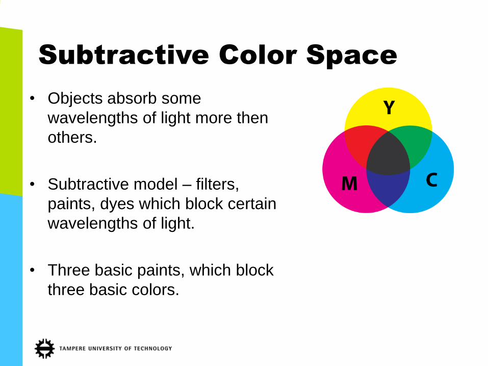
Subtractive Color Space
• Objects absorb some
wavelengths of light more then
others.
• Subtractive model – filters,
paints, dyes which block certain
wavelengths of light.
• Three basic paints, which block
three basic colors.
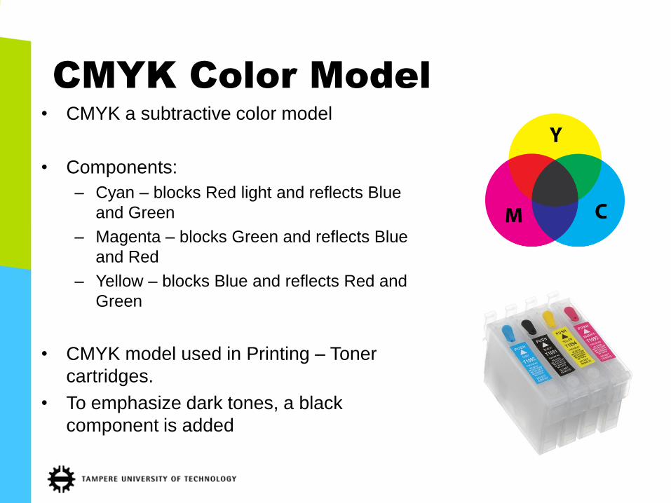
CMYK Color Model
• CMYK a subtractive color model
• Components:
– Cyan – blocks Red light and reflects Blue
and Green
– Magenta – blocks Green and reflects Blue
and Red
– Yellow – blocks Blue and reflects Red and
Green
• CMYK model used in Printing – Toner
cartridges.
• To emphasize dark tones, a black
component is added

Other Color Models
• RGB – Rectangular coordinates.
• HSV – Cylindrical coordinates.
• HSV, HSI, HSB…
– H – Hue (wavelength of color)
– S – Saturation
– B – Brightness – intensity of light
• HSV was designed for color TV, at the time of
transition from black and white TV to color TV.
• Signal needed to be encoded using 3
components to transfer color, but in a way that
black and white TV sets could use
• Black and white TVs would use only one
component (intensity) of light

2D vs. 3D graphics
• 3D – three dimensional graphics
• Physical world has 3 spatial dimensions
– Width
– Height
– Length
• 2D graphics – projection of 3D objects on planar space.
• Two dimensional graphic representations used in everyday communication: – Letters, Typography, 2D drawings and paintings, photography etc.
• Most display devices are (still) two dimensional.

2D vs. 3D computer graphics
• 2D graphics
– most of current GUIs
– photos and video
• 3D Graphics:
–video games
–VR
–augmented reality
–simulations
–military applications
stereoscopic/multiview 3D

Types of 2D Computer
Graphics
• Raster (Pixel, Bitmap) graphics
• Vector graphics

Raster 2D Graphics
• Image is a grid of pixels
• Pixels correspond to active cells on 2D screens
• A numerical value indicating intensity of light assigned
with each pixel.
• Values of individual pixels stored in a matrix
• Data structure – Matrix

Raster Graphics
• Most simple way of representing graphics
• Most widely used.
• Only way most displays can represent graphics
• All other types of graphics need to be converted
to raster graphics

Pixel depth
• Pixels – integer valued.
• Pixel depth, number of discrete values each pixel
can take.
• Pixel depth, expressed in bits needed to encode all
possible pixel values:
– 1bit – 2 values (Black and White)
– 2bit – 4 values
– 4bit – 16 values
– 8bit – 256 values

Pixel Depth
1-bit 2-bit 8-bit

Color Channels
• Grayscale – one matrix with light
intensity.
• Color image – three matrices
representing intensity of basic
colors Red, Green, Blue.
• Three Channels:
– Red
– Green
– Blue
• 3x8=24-bit graphics

Alpha Channel
• Opacity/Transparency – numerical value assigned to
each pixel
• Additional 4th channel

Image Resolution
• When visualized, pixels need to be converted into physical dots
• Size of physical dots depends on technology
– active elements on screen
– ink dots on paper
• Physical size of image not the same as size in pixels
• Resolution - number of pixels that can fit on certain physical area
• Printing resolution: Dots Per Inch (typical value: 300 DPI)
• Display resolution: Pixels Per Inch
– 42” HDTV: 20 PPI
– desktop monitors: 72 PPI
– new mobile displays: 300+ PPI

Data Compression
• ”Raw” raster images very large
• 24bit = 3 bytes x 16Mpixels = 48Mb.
• Two types of compression:
– Lossy
– Lossless
• Lossy – discard information that is not perceived by the human
observer
• Lossless – as any generic data compression

File Formats
• Several file formats with wide acceptance:
• JPG:
– lossy compression
– small file size
– can lead to visual artifacts
– does not support alpha channels
• GIF:
– lossless compression
– supports only 8-bit graphics
– 1-bit alpha channel
• PNG:
– lossless compression
– 24-bit graphics
– 8-bit alpha
• BMP, TIF, PSD…

File Format usage
File Usage
JPG Photos
GIF Short clips of cats
BMP Rarely used
PNG GUI elements, screenshots
TIFF Archival, medical images
RAW Unprocessed camera data
PSD Work in progress

Raster Graphics Software
• Industrial Standard:
– Adobe Photoshop
• Free Open Source:
– Gimp:
http://www.gimp.org/

Vector 2D Graphics
• Image described analytically.
• Image consists of elements.
• Elements – primitive objects,
lines, circles, squares, etc.

Vector Graphics
• Image consists of elements.
• Image a hierarchy of elements.
• Attributes assigned to elements.
• Attributes describe properties of
elements.
– Position
– Size
– Rotation
– Color
– Line width
– Etc.
Image
Circle
X=250mm
Y=150mm
Fill
Solid
Color=”Yellow”
Outline
Width = 1mm

Applications of Vector
Graphics
• Technical drawings – CAD
• Illustrations
• Typography – Fonts are almost always vector
images

Vector vs. Raster
• Vectors – resolution independent (scalable)
• Raster – resolution dependent (resampling)
• Vectors easier to manipulate logically
• Raster only way to represent photos
• Raster only way to display graphics on monitor

Conversion
• Rasterization – process of converting vector
graphics to raster graphics.
• Vectorization – process of converting raster
graphics to vector graphics.

Vectorization
http://research.microsoft.com/en-
us/um/people/kopf/pixelart/supplementary/comparison_bicubic.html
31.10.2012 32

Vector File Formats
• No universal standard
• Conversion hard, as different formats support different features
• SVG – XML based open source format
• AI – Adobe Illustrator format
• Many formats for CAD applications
• TTF – True Type Fonts

Vector Editing Software
• Commercial:
– Adobe Illustrator
– CorelDRAW
• Free Open Source:
– Inkscape
http://inkscape.org/
– xFig (Linux)

3D GRAPHICS
31.10.2012 35

3D Graphics
• Many ideas taken from Vector 2D
Graphics
• Scene described analytically
• Many types of 3D graphics

3D Scene
• 3D Scene, a hierarchy of elements.
• Scene:
– Geometry of objects:
• Position
• Size
• Shape
– Appearance of objects
• Color
• Texture
• Etc.

Scene Graph
• Scene Graph is a datastructure used to store
information about the state of 3D scene.
• Scene graph is a hierarchy of objects.
• Scene graph stores information about size,
position, orientation, shape and properties of
objects.
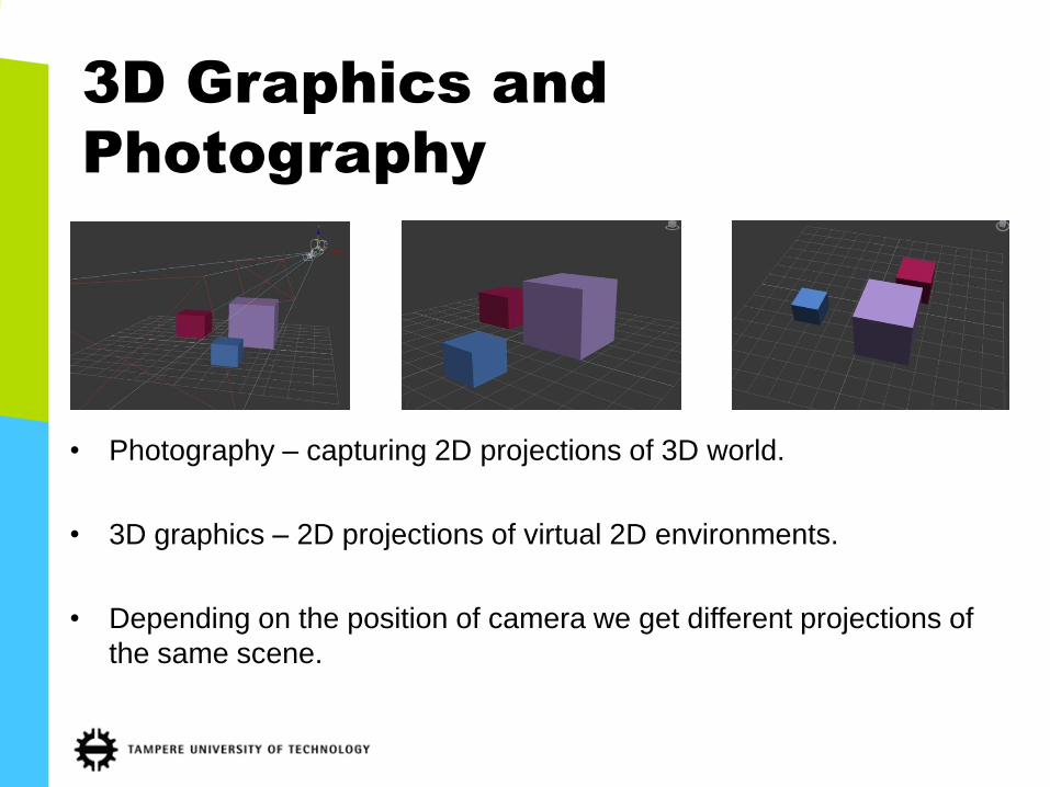
3D Graphics and
Photography
• Photography – capturing 2D projections of 3D world.
• 3D graphics – 2D projections of virtual 2D environments.
• Depending on the position of camera we get different projections of
the same scene.

Viewport
• To be displayed on screen 3D graphics needs to be projected
to 2D plane.
• Viewport is a 2D surface upon 3D scene is projected.

Projections
• Orthogonal projection:
– Parallel lines stay parallel
• Perspective projection:
– Parallel lines converge

Perspective

GEOMETRY
31.10.2012 43

Geometry Descriptions
• Several ways to describe the shape of 3D objects
• Most common in VR systems
• Polygonal mesh
• Other types:
– NURBS (non-uniform rational B-splines)
– Procedural
– Boolean operations
– Voxels (3D Pixels)

Polygonal Mesh
• Vertex – Point in 3D space
• Polygon – a plane bounded by a closed path
– Usually a triangle
• Mesh – description of an object surface consisting of a
series of polygons

Polygonal Mesh Example

Polygon Normals
• The normal is perpendicular to the surface
in 3D space in which the polygon lies
• Normal vector is defined for each polygon
• Used in many 3D algorithms to create
effects which depend on the orientation of
the surface
• Visibility to the camera, light behavior,
(physics simulation)

Level of Detail
• 3D surface – Approximation of a real surface using a finite number
of polygons
• More polygons – better approximation
• More polygons – higher level of detail
• More polygons – computationally heavy
• Great level of detail not always necessary, i.e. object distant from
viewer
• Adjustable level of detail – way to reduce the computational
requirements

Level of Detail

Z-buffer
• Visibility problem – which 3D
objects are visible in the given 2D
viewport, and which are occluded
• Z-buffer – distance of object from
the viewport plane
• Used for many algorithms
• Generated often in hardware

RENDERING
31.10.2012 51

Rendering
• Object = Geometry + Material
• Material properties describe how objects interact with
light
• Color, reflection, refraction, opacity/transparency,
texture, etc.
• Rendering – process of generating a 2D image from a
3D description of objects

Rendering Algorithms
• Rendering – trying to model optical properties of a
material:
– Reflected light
– Refracted light
• Several rendering algorithms
• Algorithms differ in how closely they approximate the
real physical process
• Algorithms differ in computational complexity

Lambertian Rendering
• Simplest rendering model
• Used to model diffuse light
• All incoming light gets reflected by object equally in all directions
• Appearance of object surface does not depend on position of the
virtual camera
• Appearance depends on position of light source

Phong Rendering
• More complex then Lambertian
• Empirical model of local illumination
(approximation)
• Reflected light = Diffuse component +
Specular component
• Diffuse component – same as in Lambertian
model
• Specular component – shiny areas
• Specular component depends both on the
position of virtual camera and light source

Gouraud shading
• Polygons – flat surfaces in 3D space
• Gouraud shading – used to give appearance of smooth surface to
polygonal mesh.
• Uses polygon normals
• Complements other rendering models, such as Phong

Gouraud shading
Flat Shaded
Low Detail Gouraud
Low Detail
Flat Shaded
High Detail
• Doesn’t increase number of polygons
• Computationally not heavy

Gouraud shading
• Normal at vertex V is calculated as an average of normals of
polygons which meet at V.
• Normals of pixels of polygon surface are calculated as linear
interpolations of normals at polygon vertices.

Texture mapping
• Method of adding detail to 3D objects
• Method of simulating surface textures
• Texture a – 2D raster image
• Mapping from 2D texture coordinates onto 3D object coordinates

Texture mapping

Texture Mapping
• X,Y – rectangular coordinates in 2D spaces are mapped to U,V
coordinates on the surface of object.
• Mapping – non-linear.
• We need to specify how this mapping is done.
• Planar, Spherical, etc.

Bump Mapping
• Special kind of texture mapping
• Doesn’t affect color of the object directly
• Adds detail to object surface without increasing the number of polygons
• Method of modeling small bumps on objects which would otherwise require
enormous number of polygons

Bump Mapping
• Bump map – a monochrome raster image
• For each pixel, a fake surface normal is computed based on the
bump map and the actual normal of the surface

Bump Mapping
• Has no effect on the actual geometry
Bump mapped Distorted mesh

Environment Mapping
• Fast solution for rendering approximate
reflections on shiny surfaces
• Render once the environment around the
object into an environment map
• Map this environment map onto the object
• Environment Maps – fast to compute, good for
real time
• Good enough visual impression
• Unrealistic

Radiosity
• Realistic distribution of light energy over surfaces
• Based on finite element numeric approximation method – Object surface is divided in many
small surfaces
• Traces light rays that originate at light sources as the reflected by objects – Opposite approach to ray tracing
• Number of ray bounces is limited to reduce computational complexity

Radiosity
• Complementary to ray tracing:
– Ray tracing for reflections and
refractions
– Radiosity for diffuse surfaces
• Light distribution via radiosity
can be computed only once
– Suitable for real time
applications
– Relies on static lighting
• Applications especially in
architecture

Image Based Lightning
• Evolution of Environment Mapping
• Environment map serves as a light
source
• Light Rays projected from map onto
the object
• Color of pixels on the map
determines the color and brightness
of regions on object
• Very realistic results
• Suitable for real time applications

Real time 3D graphics
• In practice, games
• Battlefield 3, 2011: youtu.be/8pNOxynC1Dc
• Crysis 3, 2013: youtu.be/JWvgETOo5ek
Upcoming
• Luminous Studio (Final Fantasy):
youtu.be/HdGxUyGc1tg
• Unreal Engine 4: youtu.be/dD9CPqSKjTU
31.10.2012 69

Ray Tracing
• “Traditional” rendering techniques explicitly model effects light
experiences in the scene
• Ray Tracing tries to simulate the behavior of individual light rays
– Shadows, reflections are produced implicitly
• In real life
– Ray of light starts from a light source
– Gets reflected and refracted many times on various objects
– Arrives at the eye of the observer
• Many rays get scattered and absorbed, never reaching an observer
• Ray tracing does the process in reverse
• Rays are shot from the observer to determine if they hit light sources

Ray Tracing
• A ray of light is shot from virtual camera through every pixel in view
port.
• Each time a ray hits a surface three new rays are generated:
– Shadow
– Reflection
– Refraction
Ray Tracing
• Shadow ray – from a point where incoming ray hits the object
directly to light source
– If there is another object in the path of shadow ray, object is in the
shadow
• Reflection ray – simulates reflected part of light of an original ray
• Refraction ray – simulates refracted part of light
– used only if object is semi-transparent

Ray Tracing
• Result depends on:
– Position of camera
– Position of light sources
– Position of objects
• Computationally very heavy
– Number of rays grows exponentially
– Needs to be done for every frame
– Most problems are solved and features added by shooting more and
more rays
• To reduce computational complexity, number of ray bounces is
limited (user defined parameter)

Ray Tracing
• Alex Roman
– Above Everything Else, 2010:
http://vimeo.com/15630517
– The Third & The Seventh, 2010:
http://vimeo.com/7809605
• Very realistic
• Very slow
• Real-time, practical implementations are starting to emerge
– Nvidia, 2010: http://vimeo.com/10686515
– Nvidia, 2012: http://youtu.be/w9SH8xlgzoI#t=126s

3D File Formats
• No universal standard
• Big differences in supported features
• Always problems in conversion
• Popular formats: – OBJ - Old Alias|Wavefront format - Structured ASCII
– 3DS - Old Autodesk 3D Studio for DOS format
– Collada
– FBX - modern exchange formats
– SKP - Google Sketchup Format - Many free 3D models

3D Software – General
Purpose
• Industrial Favorites:
– 3Ds Studio MAX
– Maya
– Softimage
• Available under academic license from Autodesk
• http://students.autodesk.com/
– Register using your TUT student email!

3D Software – General
Purpose
• Free:
– Google Sketchup
http://sketchup.google.com/
• Open Source:
– Blender
http://www.blender.org/

Specialized 3D software
• Character animation:
– Daz Studio:
http://www.daz3d.com/products/daz-studio/
– Version 4.5 is free
• Landscape:
– Vue
http://www.vue10.com/ple/
– Free as Personal Learning Edition

Free 3D Models
• Google 3D Warehouse:
– http://sketchup.google.com/3dwarehouse/
• Daz 3D Models
– http://www.daz3d.com/shop/free-3d-models-
and-content

GRAPHICS ARCHITECTURE
31.10.2012 80

Graphics System
Architecture
AMD Radeon, Nvidia GeForce,
PowerVR SGX, ARM Mali...
Always specific for the graphics card
OpenGL, Direct3D, (CUDA, OpenCL)…
Frostbite, Unreal Engine,Unity,
id Tech 4, OptiX…
Battlefield 3, Gears of War 3, Doom 3,
Design Garage…
Rasterized image
3D models, scene graph
Vertices, textures
Display
Graphics Card
Device drivers
Middleware
3D Engine
Applications

Graphic Hardware
• Graphics Processing Unit (GPU)
• Dedicated processor for graphics
manipulation
– Massive amounts of matrix operations
– low level of data dependency
– high data level parallelism

GPU vs. CPU
• CPU - Single Instruction Single Data architecture (SISD)
• GPU - Single Instruction Multiple Data (SIMD)
• GPU - Hundreds of processing units, which all perform the same
operation on varying data in parallel

GPU vs. CPU – Raw Power
• Most Powerful GPUs - Tesla S2050 - 4121.6 GFlops
• Two companies control most of the desktop market:
• Nvidia – (GeForce, Quadro, Tesla) • AMD/ATi (Radeon)

Graphics Memory
• Used on Graphics cards - GDDR
• Different properties to standard system memory
• Two notable properties:
– Big latency
– Big bandwidth

Middleware
• Libraries of programming functions that can be evoked by applications to render 3D graphics.
• Handling of geometry, lighting, textures, etc.
• Two competing platforms: – OpenGL
• Open Source
• Various OS, Windows, Linux, OSX, iOS, etc.
• Khronos Group
– Direct3D • Microsoft proprietary
• Windows, Xbox

3D Engine
• 3D Engine - built on top of middleware. Handles more high level
operations.
• Rendering of objects.
• Handling the scene graph.
• Collision detection.
• Physics Simulations.
• User Interaction.
• Sound.
• Artificial Intelligence.
• etc.

3D Engines
• Many free or commercial 3D engines of various quality
and with wide range of features:
• Free for personal use:
– Unreal Engine 3 - Unreal Development Kit
http://www.udk.com/
– Unity 3D Engine
http://unity3d.com/

ALTERNATE APPROACHES
31.10.2012 89

Representing realistic
scenes
10/31/2012 90
Explicit geometrical information
Amount
of data
Holography
Light field
Photograph
3D computer
graphics
Point cloud
Depth Image-
based rendering
Panorama

Depth Image based
rendering (DIBR)
• Inputs:
– 2D view of the scene
– Depth map of the scene
• Output:
– 2D view of the scene
from a ”virtual” viewpoint
31.10.2012 91

DIBR
• Could be achieved with 3D graphics:
– Create a mesh from the depth map
– Apply 2D view as texture
– Rotate/translate the scene in 3D space
– Rasterize
• Consider the difference between the
images from horizontally translated
cameras
– Things have moved in one direction
– No need to go through all the trouble
– Just find out how much things should move
31.10.2012 92

Disparity from depth
31.10.2012 93
fz
b
*
Lx *
Rx
**
RL xxd
)0,0(
),0( f ),( fb ),(' fxP RR ),(' fxP LL
),( zxP

Moving things
• As seen in the figure, the amount of moving (disparity)
depends on the depth of the thing
– Specifics are left for the bonus assignment
• Depth of each pixel is known, so ”thing” can be a single
pixel
• For each pixel, the disparity tells where its new location
in the virtual view is
• Virtual view is created by moving the pixels one by one
to their new locations
– Order of moving pixels is important, otherwise background could
occlude foreground
31.10.2012 94

Occlusions
• A single input view can’t have information on the
whole scene (in a general case)
• Changing viewpoint may reveal areas that are
blocked by other objects (occluded)
– Blank areas in the virtual view
• Blanks should be filled with something
– Interpolation from surrounding pixels
– Interpolation of structure
– Similar image patches etc.
31.10.2012 95

Use case: multiview display
• Encode view+depth (4/3 * 2D data)
• Receive & decode
• Apply DIBR with a different baseline setting for each
view required by the display
• Guess some content to the disoccluded areas
• Interleave views to match the pixel mask of the display
• Other possibility: encode & transmit all views
(e.g. 28 * 2D data)
31.10.2012 96

Point clouds
• A ”raw” method of representing geometry
• Consists only of points in 3D space (vertices)
– No connections between points
– Points usually lie on the surface of the object (but
could also represent volumetric information)
• When the density of the point cloud is high
enough, it looks like a surface
• Used often as an intermediary format of 3D
scanners, then converted/merged into a mesh
31.10.2012 97

Holography
• Light from the same source (laser) is
– reflected from the scene
– directed to the recording medium
• The interference pattern is recorded
• Each point on the holographic recording includes
information about light coming from every point in
the scene
• The scene is reconstructed by illuminating the
medium with light identical to the reference beam
31.10.2012 98

Image-based rendering
• “Unlike traditional 3D computer graphics in
which 3D geometry of the scene is known,
image-based rendering techniques render
novel views directly from input images.”
– Sing Bing Kang and Heung-Yeung Shum, A
Review of Image-based Rendering
Techniques
31.10.2012 99

Light fields
• Consider all light passing though space as individual
rays of light
• One parametrization of the 7D plenoptic function
• If all light rays traveling from the scene are known, a
view of the scene can be reconstructed from any point
• Each ray can be described by
intersections with two known planes
• Novel view generation becomes
a sampling problem
31.10.2012 100
Top Related