


Languages
Pages
Legal


135Sigma-II servo drive
SGDH-@
Sigma-II servo driveThe ideal servo family for motion control. Fast response, high speed, and high accuracy.• Online autotuning with 10 levels of rigidity• Peak torque 300% of nominal during 3 seconds• Automatic motor recognition• Analogue control for speed and torque• Pulse train control for positioning• Optional units offer network connectivity and flexible
system architecture • Smooth operation• Oscilloscope available via software tool• Windows based configuration and commissioning
software Ratings• 230 VAC Single-phase 30 W to 1.5 kW (4.77 Nm)• 400 VAC Three-phase 450 W to 55 kW (350 Nm)
System configuration
Cables Cables
CHARGE POWER
SERVOPACK
SGDH-
200VVer.
CN3
CN1
CN2
SGMGH, SGMUH, SGMSH, SGMBH Servo Motor
(Refer to chapter Sigma-II linear motors)
SGMAH, SGMPHServo Motor
Position controlunit
Terminal block position control
General purpose cable
Motion control unit
Digital operator
Option unit- 1 MECHATROLINK I/II- 2 DeviceNet- 3 PROFIBUS- 4 Motion controller- 5 Indexer
Battery for absolute encoder
Analog monitor cable
Filter
For higher drive size
External regenerative resistorDynamic brake resistor
Sigma-II series
Servo Drives
SGLT_ linearServo Motor
SGLG_ linearServo Motor
SGLF_ linear Servo Motor
(Refer to chapter Sigma-II rotary motors)
Personal computer
NS115
SW1
SW2
AR
CN6A
CN6B
CN4
Y203-EN2-02-Katalog.book Seite 135 Mittwoch, 24. Mai 2006 2:22 14
AUDIN - 8, avenue de la malle - 51370 Saint Brice Courcelles - Tel : 03.26.04.20.21 - Fax : 03.26.04.28.20 - Web : http: www.audin.fr - Email : [email protected]

136 AC servo systems
Servo drive
Servo motor supported
Servo motorFamily Voltage Models rated torque RemarksSGMAH(3000 min-1)
230 V 0.0955 Nm to 2.39 Nm Refer to the Sigma-II rotary motors chapter for details
400 V 0.955 Nm to 2.07 Nm
SGMPH(3000 min-1)
230 V 0.318 Nm to 4.77 Nm Refer to the Sigma-II rotary motors chapter for details
400 V 0.637 Nm to 4.77 Nm
SGMGH(1500 min-1)
400 V 2.84 Nm to 95.4 Nm Refer to the Sigma-II Rrotary motors chapter for details
SGMSH(3000 min-1)
400 V 3.18 Nm to 15.8 Nm Refer to the Sigma-II Rrotary motors chapter for details
SGMUH(6000 min-1)
400 V 1.59 Nm to 6.3 Nm Refer to the Sigma-II rotary motors chapter for details
SGMBH(1500 min-1)
400 V 140 Nm to 350 Nm Refer to the Sigma-II rotary motors chapter for details
SGLGWLinear motors
230 V 12.5 N to 325 N Refer to the Sigma linear motors chapter for details
SGLFWLinear motors
230 V 25 N to 560 N Refer to the Sigma linear motors chapter for details
400 V 80 N to 2250 N
SGLTWLinear motors
400 V 300 N to 2000 N Refer to the Sigma linear motors chapter for details
Type designation
A3 30 W50 W100 W200 W400 W
750 W
A5010204
08
1.5 kW2.0 kW3.0 kW5.0 kW
7.5 kW
15203050
75
1.0 kW1011 kW1A15 kW1E
500 W056.0 kW60
Blank
S Single-phase (750W/1.5kW)
Three-phase (0.5 to 55kW)Single-phase (30 to 400W)
Sigma-II servo drive
CapacityModel E: speed, torque, position
Source voltage A: 230 V
D: 400 V
SGDH - 04 A E - S - OYPhase
22 kW30 kW37 kW45 kW
2B3Z3G4E
55 kW5E
Y203-EN2-02-Katalog.book Seite 136 Mittwoch, 24. Mai 2006 2:22 14
AUDIN - 8, avenue de la malle - 51370 Saint Brice Courcelles - Tel : 03.26.04.20.21 - Fax : 03.26.04.28.20 - Web : http: www.audin.fr - Email : [email protected]
Sigma-II servo drive 137
Single-phase, 230 V
Three-phase, 400 V (up to 15 kW)
Three-phase, 400 V (from 22 kW to 55 kW)
General specifications
Servo drive specifications
Servo drive type SGDH- @ A3AE-OY A5AE-OY 01AE-OY 02AE-OY 04AE-OY 08AE-S-OY 15AE-S-OYApplicable servo motor
SGMAH-@ A3A@ A5A@ 01A@ 02A@ 04A@ 08A@ -SGMPH-@ - - 01A@ 02A@ 04A@ 08A@ 15A@
Bas
ic s
peci
ficat
ions
Max. applicable motor capacity W 30 50 100 200 400 750 1500Continuous output current Arms 0.44 0.64 0.91 2.1 2.8 5.7 11.6Max. output current Arms 1.3 2.0 2.8 6.5 8.5 13.9 28Input power Main circuit For single-phase, 200 to 230 VAC + 10 to -15% 220 to 230 VAC
+10 to -15% (50/60 Hz)Supply Control circuit For single-phase, 200 to 230 VAC + 10 to -15% Control method Single phase full-wave rectification / IGBT / PWM / sine-wave current drive methodFeedback Serial encoder (incremental/absolute value)
Con
ditio
ns Usage/storage temperature 0 to +55 °C / -20 to 85 °CUsage/storage humidity 90%RH or less (non-condensing)Altitude 1000m or less above sea levelVibration/shock resistance 4.9 m/s2 / 19.6 m/s2
Configuration Base mounted Approx. weight Kg 0.8 1.1 1.7 3.8
Servo drive type SGDH-@ 05DE-OY 10DE-OY 15DE-OY 20DE-OY 30DE-OY 50DE-OY 60DE-OY 75DE-OY 1ADE-OY 1EDE-OYApplicable servo motor
SGMGH-@ 05D@ 09D@ 13D@ 20D@ 30D@ 44D@ 55D@ 75D@ 1AD@ 1ED@SGMSH-@ - 10D@ 15D@ 20D@ 30D@ 40D@/50D@ - - - -SGMUH-@ - 10D@ 15D@ - 30D@ 40D@ - - - -
Bas
ic s
peci
ficat
ions
Max. applicable motor capacity kW 0.45 1.0 1.5 2.0 3.0 5.0 6.0 7.5 11 15Continuous output current Arms 1.9 3.5 5.4 8.4 11.9 16.5 20.8 25.4 28.1 37.2Max. output current Arms 5.5 8.5 14 20 28 40.5 55 65 70 85Input power Main circuit For three-phase, 380 to 480 VAC + 10 to -15% (50/60Hz) Supply Control circuit 24 VDC+ 15%Control method Three phase full-wave rectification / IGBT / PWM / sine-wave current drive methodFeedback Serial encoder (incremental/absolute)
Con
ditio
ns
Usage/storage temperature 0 to +55 °C / -20 to +85 °CUsage/storage humidity 90%RH or less (non-condensing)Altitude 1000 m or less above sea levelVibration/shock resistance 4.9 m/s2 / 19.6 m/s2
Configuration Base mounted Approx. weight Kg 2.8 3.8 5.5 13.5 22
Servo drive type SGDH-@ 2BDE 3ZDE 3GDE 4EDE 5EDEApplicable servo motor SGMBH-# 2BD#A 3ZD#A 3GD#A 4ED#A 5ED#A
Bas
ic s
peci
ficat
ions
Max. applicable motor capacity kW 22 30 37 45 55Continuous output current Arms 58 80 100 127 150Max. output current Arms 120 170 210 260 310Input power Main circuit For three-phase, 380 to 480 VAC + 10 to -15% (50/60 Hz) Supply Control circuit 24 VDC+ 15%Control method Three phase full-wave rectification / IGBT / PWM / sine-wave current drive methodFeedback Serial encoder (incremental/absolute)
Con
ditio
ns
Usage/storage temperature 0 to +55 °C / -20 to +85 °CUsage/storage humidity 90%RH or less (non-condensing)Altitude 1000 m or less above sea levelVibration/shock resistance 4.9 m/s2 / 19.6 m/s2
Configuration Base mounted Approx. weight Kg 40 60 65
Sp
eed
/to
rqu
e co
ntr
ol m
od
e
Per
form
ance
Speed control range 1:5000Speedvariance
Load variance During 0 to 100% load ±0.01% max. (at rated speed)Voltage variance Rated voltage ±10%:0% (at rated speed)Temperature variance 25 ±25 °C: ±0.1 % max (at rated speed)
Frequency characteristics 400 Hz (at JL= JM up to 15 kW drives), 100 Hz (at JL= JM from 22 kW to 55 kW drives)Torque control accuracy (reproducibility) ±2%Soft start time setting 0 to 10 s (acceleration, deceleration can each be set.)
Inp
ut
sig
nal
Speed reference input
Reference voltage ±6 VDC (forward motor rotation if positive reference) at rated speed: set at deliveryVariable setting range: ±2 to ±10 VDC at rated speed/ max. input voltage: ±12 V
Input impedance Approx. 14 kΩ Circuit time constant Approx. 47 µs
Torque referenceinput
Reference voltage ±3 VDC (forward rotation if positive reference) at rated speed: set at deliveryVariable setting range ±1 to ±10 VDC at rated torque reference
Input impedance Approx. 14 KΩCircuit time constant Approx. 47 µs
Y203-EN2-02-Katalog.book Seite 137 Mittwoch, 24. Mai 2006 2:22 14
AUDIN - 8, avenue de la malle - 51370 Saint Brice Courcelles - Tel : 03.26.04.20.21 - Fax : 03.26.04.28.20 - Web : http: www.audin.fr - Email : [email protected]
138 AC servo systems
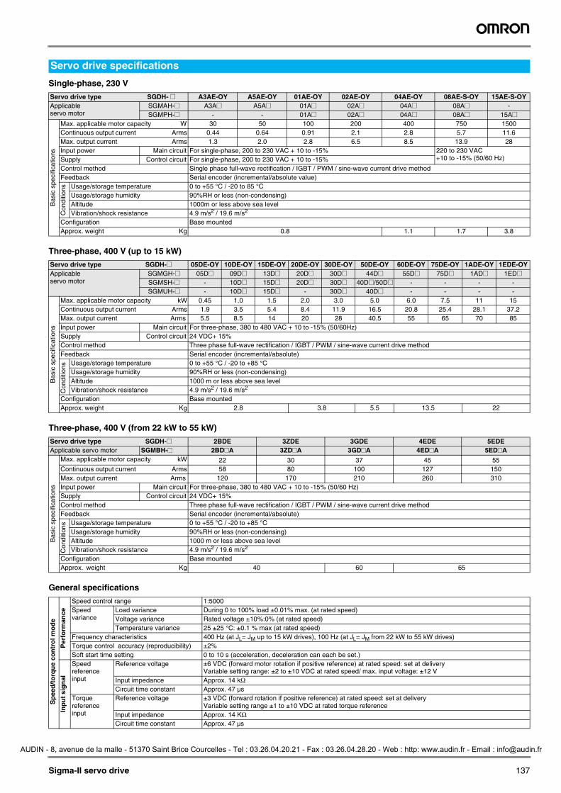
I/O specifications
I/O signals (CN1) - input signals
Note: 1. Pin numbers in parentheses () indicate signal grounds.2. The functions allocated to /S-ON, /P-CON. P-OT, N-OT, /ALM-RST, /P-CL, and /N-CL input signals can be changed by using the
parameters. 3. The voltage input range for speed and torque references is a maximum of ±12 V.
Po
siti
on
co
ntr
ol m
od
e
per
form
ance Bias setting 0 to 450 min-1 (setting resolution: 1 min-1)
Feed forward compensation 0 to 100% (setting resolution: 1%)Position completed width setting 0 to 250 command units (setting resolution: 1 command unit)
Inp
ut s
ign
al
Command pulse
Input pulse type Sign + pulse train, 90° phase displacement 2-phase pulse (A-phase+ B-phase) or CCW/CW pulse trainInput pulse form Line driver (+5 V level) , open collector (+5 V or +12 level)Input pulse frequency 0 to 500 Kpps (200 Kpps max. at open collector)
Control signal Clear signal (input pulse is same as reference pulse)
I/O s
ign
al
Position signal output A-phase, B.phase, C-phase, (S-phase): line driver output S-phase is for absolute encoder only.Sequence input signal Servo ON, P control (or control mode switching, zero clamp, command pulse inhibit), forward/reverse run prohibit,
alarm reset, forward/reverse current limit (or internal speed switching)Sequence output signal Servo alarm, alarm codes (3-bit output): CN1 output terminal is fixed
It is possible to output three types of signal form incl.: positioning complete (speed agree), motor rotation, servo ready, current limit, speed limit, brake release, warning, NEAR, and zero point pulse signal
Inte
gra
ted
fu
nct
ion
s
Communications
Interface Digital operator (hand- held type), RS-422 port for PCs, etc. (RS-232C ports under some conditions)1:N communications N may equal up to 14 when an RS-422A port is usedAxis address setting Set by user settingFunctions Status display, user constant setting monitor display, alarm traceback display, JOG run/autotuning operations,
and graphing functions for speed/torque command signal, etcAutomatic load inertia detection Automatic motor parameter setting. One parameter rigidity setting.Dynamic brake (DB) Operates during main power OFF, servo alarm, servo OFF or overtravelRegenerative processing Internal resistor included in models from 500 W to 5 kW. Regenerative resistor externally mounted (option).Overtravel (OT) prevention function DB stop, deceleration stop or coast to stop during P-OT, N-OT operationEncoder divider function Optional division possibleElectronic gearing 0,01< A/B<100Internal speed setting function 3 speeds may be set internallyProtective functions Overcurrent, overvoltage, insufficient voltage, overload, main circuit sensor error, heatsink overheat, power phase
loss, overflow, overspeed, encoder error, runaway, CPU error, parameter error, etc.Analog monitor functions for supervision Integrates analog monitor connectors for supervision of the speed and torque reference signals, etc.Display functions CHARGE, POWER, 7-segments LEDx5 (integrated digital operator function)Others Reverse connection, zero search, automatic motor discrimination function, and DC reactor connection terminal
for high frequency power suppression function (except: 6 to 15 kW)
Pin No. Signal name Function40 Common /S-ON Servo ON: Turns ON the servo motor when the gate block in the inverter is released.41 /P-CON Function selected by parameter.
Proportional control reference Switches the speed control loop from PI (proportional/integral) to P (proportional) control when ON.
Direction reference With the internal set speed selected: switch the rotation direction.Control mode switching
Zero-clamp reference Speed control with zero-clamp function: reference speed is zero when ON.Reference pulse block Position control with reference pulse stop: stops reference pulse input when ON.
4243
P-OTN-OT
Forward run prohibitedReverse run prohibited
Overtravel prohibited: Stops servo motor when movable part travels beyond the allowable range of motion.
4546
/P-CL/N-CL
Function selected by parameter. Forward external torque limit ONReverse external torque limit ON
Current limit function enabled when ON.
Internal speed switching With the internal set speed selected: switches the internal speed settings.44 /ALM-RST Alarm reset: releases the servo alarm state.47 +24VIN Control power supply input for sequence signals: users must provide the +24 V power supply.
Allowable voltage fluctuation range: 11 to 25 V4 (2) SEN Initial data request signal when using an absolute encoder.2122
BAT (+)BAT (-)
Connecting pin for the absolute encoder backup battery.Do not connect when a battery is connected to the host controller.
5 (6) Speed V-REF Speed reference input: ±2 to ±10 V/rated motor speed (input gain can be modified using a parameter.)9 (10) Torque T-REF Torque reference input: ±1 to ±10 V/rated motor torque (input gain can be modified using a parameter.)781112
Position PULS/PULS SIGN/SIGN
Reference pulse inputfor line driver only
Input mode is set from the following pulses.Sign + pulse stringCCW/CW pulseTwo-phase pulse (90° phase differential)
1514
CLR/CLR
Positional error pulse clear input: clears the positional error pulse during position control.
31318
PL1PL2PL3
+12 V pull-up power is supplied when PULS, SIGN, and CLR reference signals areopen-collector outputs (+12 V power supply is built into the SERVOPACK).
Position speed
Position torque
Torque speed
Enables control mode switching
↔
↔
↔
Y203-EN2-02-Katalog.book Seite 138 Mittwoch, 24. Mai 2006 2:22 14
AUDIN - 8, avenue de la malle - 51370 Saint Brice Courcelles - Tel : 03.26.04.20.21 - Fax : 03.26.04.28.20 - Web : http: www.audin.fr - Email : [email protected]
Sigma-II servo drive 139
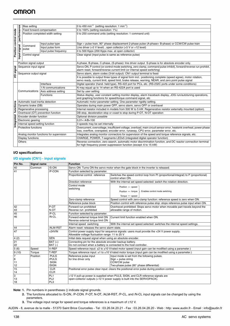
I/O signals (CN1) - output signals
Note: 1. Pin numbers in parentheses () indicate signal grounds.2. The functions allocated to /TGON, /S-RDY, and /V-CMP (/COIN) can be changed by using the parameters. /CLT, /VLT, /BK, /WARN, and
/NEAR signals can also be changed.
Terminal specifications (all drives)
Terminal specifications (from 22 kW to 55 kW)
Encoder connector (CN2)
Pin No. Signal Name Function3132
Common ALM+ALM-
Servo alarm: Turns OFF when an error is detected.
2728
/TGON+/TGON-
Detection during servo motor rotation: detects when the servo motor is rotating at a speed higher than the motor speed setting. Detection speed can be set by using the parameters.
2930
/S-RDY+/S-RDY-
Servo ready: ON if there is no servo alarm when the control/main circuit power supply is turned ON.
33 (1)34
PAO/PAO
Phase-A signal Converted two-phase pulse (phases A and B) encoder outputSignal and zero-point pulse (phase C) signal: RS-422 or the equivalent(proper line receiver is SN75175 manufactured by Texas Instruments or the equivalent corresponding to MC3486.)
3536
PBO/PBO
Phase-B signal
1920
PCO/PCO
Phase-C signal
4849
PSO/PSO
Phase-S signal With an absolute encoder: outputs serial data corresponding to the number of revolutions (RS-422 or the equivalent)
373839 (1)
ALO1ALO2ALO3
Alarm code output: Outputs 3-bit alarm codes.Open-collector: 30 V and 20 mA rating maximum
Shell FG Connected to frame ground if the shield wire of the I/O signal cable is connected to the connector shell.2526
Speed /V-CMP+/V-CMP-
Speed coincidence (output in speed control mode): detects whether the motor speed is within the setting range and if it matches the reference speed value.
2526
Position /COIN+/COIN-
Positioning completed (output in position control mode): turns ON when the number of positional error pulses reaches the value set. The setting is the number of positional error pulses set in reference units (input pulse units defined by the electronic gear).
- Reserved /CLT/VLT/BK/WARN/NEAR
Reserved terminalsThe functions allocated to /TGON, /S-RDY, and /V-CMP (/COIN) can be changed by using the parameters. /CLT, /VLT, /BK, /WARN, and /NEAR signals can also be changed.
1617232450
- Terminals not usedDo not connect relays to these terminals.
Symbol Name FunctionL1, L2 orL1, L2, L3 orL1/R, L2/S, L3/T
Main circuit AC input terminal AC power input terminals for the main circuit
U Servo motor connection terminal Red Terminals for outputs to the servo motor.V WhiteW BlueL1C, L2C Control power input terminal AC power input terminals for the control circuit.
Frame ground Ground terminal. Ground to a maximum of 100 Ω. (class 3)
B1, B2 orB1, B2, B3
Main circuit DC output terminal Up to 5 kW: Connect an external regenerative resistor if regenerative energy is high.From 5.5 kW to 55 kW: There is no internal regenerative resistor. Be sure to connect an external
regenerative resistor unit.⊕1, ⊕2 DC reactor connection terminal for
suppressing power supply harmonic waves
Normally, short ⊕1 and ⊕2.If a countermeasure against power supply harmonic waves is needed, connect a DC reactor between ⊕1 and ⊕2.
⊕ Main circuit DC output terminal (positive)
Normally, not connected.This terminal exists on the servo drives with a capacity of 6.0 kW or higher only.
Main circuit DC output terminal (negative)
Normally, not connected.
Symbol Name FunctionDC24P,DC24N Control power supply input terminal 24 VDCDU, DV, DW DB resistor unit,
DB contactor connection terminalConnects DB resistor unit or DB contactor.
DBON, DB24 DB resistor unit connection terminal For 37 to 55 kW, connects to DBON and DB24 terminals or DB resistor unit.480 V, 460 V, 440 V, 400 V,380 V, 0 V
Control power Supply input Terminal
Connect to the terminal whose voltage is close to the power supply voltage.
Pin No. Signal Name Function1 E5V Encoder power supply + 5 V2 E0V Encoder power supply ground3 BAT+ Battery + (used only with absolute encoder)4 BAT– Battery – (used only with absolute encoder)5 S+ Encoder serial signal input6 S– Encoder serial signal input
Y203-EN2-02-Katalog.book Seite 139 Mittwoch, 24. Mai 2006 2:22 14
AUDIN - 8, avenue de la malle - 51370 Saint Brice Courcelles - Tel : 03.26.04.20.21 - Fax : 03.26.04.28.20 - Web : http: www.audin.fr - Email : [email protected]
140 AC servo systems
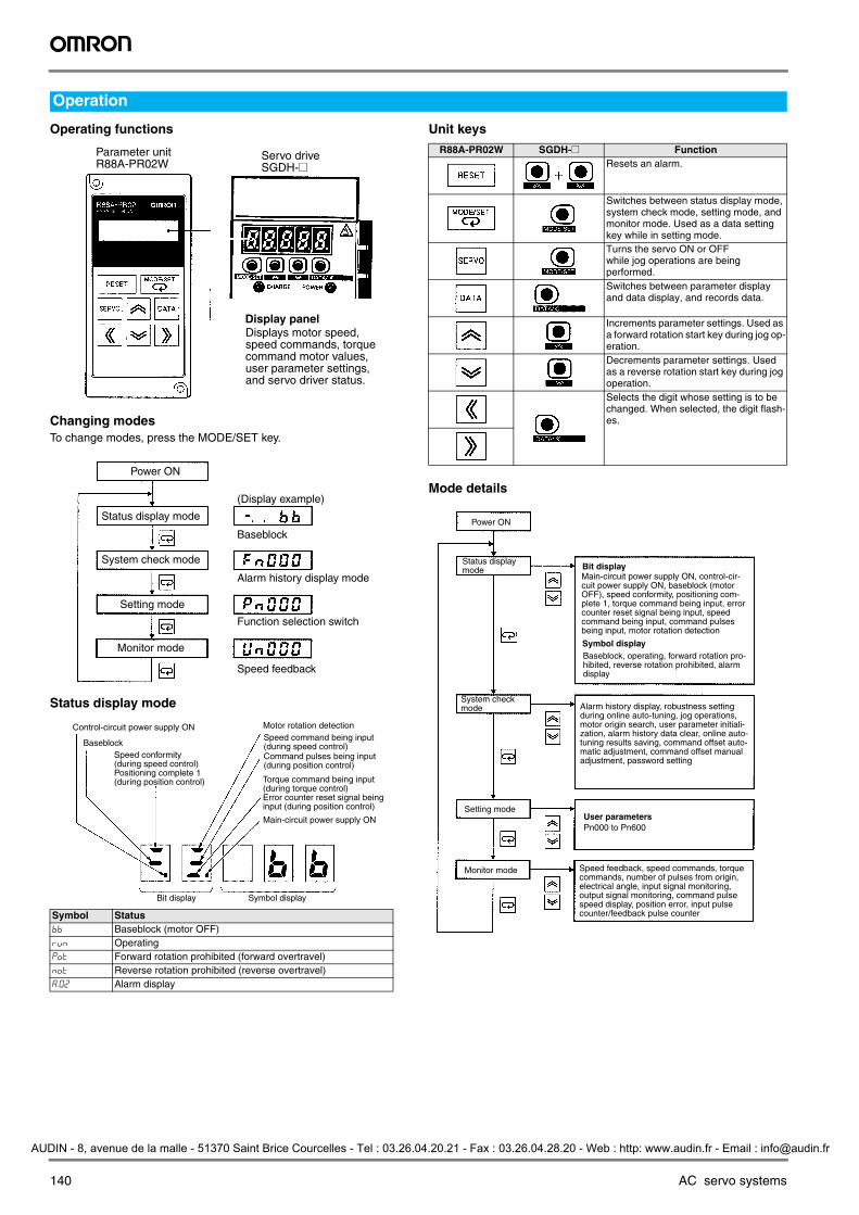
Operating functions
Changing modesTo change modes, press the MODE/SET key.
Status display mode
Unit keys
Mode details
Operation
Symbol Statusbb Baseblock (motor OFF)rUn Operatingp%t Forward rotation prohibited (forward overtravel)n%t Reverse rotation prohibited (reverse overtravel)a.02 Alarm display
Display panel
Parameter unit R88A-PR02W
Servo drive SGDH-@
Displays motor speed, speed commands, torque command motor values, user parameter settings, and servo driver status.
Power ON
Status display mode
System check mode
Setting mode
Monitor mode
Baseblock
Alarm history display mode
Function selection switch
Speed feedback
(Display example)
Control-circuit power supply ON
Baseblock
Motor rotation detection
Main-circuit power supply ON
Bit display Symbol display
Speed conformity (during speed control) Positioning complete 1 (during position control)
Speed command being input (during speed control)Command pulses being input (during position control)
Torque command being input (during torque control) Error counter reset signal being input (during position control)
R88A-PR02W SGDH-@ FunctionResets an alarm.
Switches between status display mode, system check mode, setting mode, and monitor mode. Used as a data setting key while in setting mode.Turns the servo ON or OFF while jog operations are being performed.Switches between parameter display and data display, and records data.
Increments parameter settings. Used as a forward rotation start key during jog op-eration.Decrements parameter settings. Used as a reverse rotation start key during jog operation.Selects the digit whose setting is to be changed. When selected, the digit flash-es.
Power ON
Bit display
Symbol display
Monitor mode
Setting modeUser parametersPn000 to Pn600
Status display mode
Main-circuit power supply ON, control-cir-cuit power supply ON, baseblock (motor OFF), speed conformity, positioning com-plete 1, torque command being input, error counter reset signal being input, speed command being input, command pulses being input, motor rotation detection
Baseblock, operating, forward rotation pro-hibited, reverse rotation prohibited, alarm display
System check mode Alarm history display, robustness setting
during online auto-tuning, jog operations, motor origin search, user parameter initiali-zation, alarm history data clear, online auto-tuning results saving, command offset auto-matic adjustment, command offset manual adjustment, password setting
Speed feedback, speed commands, torque commands, number of pulses from origin, electrical angle, input signal monitoring, output signal monitoring, command pulse speed display, position error, input pulse counter/feedback pulse counter
Y203-EN2-02-Katalog.book Seite 140 Mittwoch, 24. Mai 2006 2:22 14
AUDIN - 8, avenue de la malle - 51370 Saint Brice Courcelles - Tel : 03.26.04.20.21 - Fax : 03.26.04.28.20 - Web : http: www.audin.fr - Email : [email protected]

Sigma-II servo drive 141
Servo drives
SGDH-A3AE-OY to -02AE-OY (230 V, 30 to 200 W)
SGDH-04AE-OY (230 V, 400 W)
SGDH-08AE-S-OY (230 V, 750 W)
Dimensions
Ground terminal2´M4 screws
(Mou
ntin
g pi
tch)
160
5
5.5
149.
5±0.
5 CN3
CN2
CN1
55
160
10 6
6
130 75
5
39
106
8
2´M4 screw holes
Mounting hole diagram
Terminalblock
55
CN10
CHARGE POWER
SERVOPACK
SGDH-
200VVer.
CN3
CN1
CN2
149.
5±0.
5
12
75
CN3
CN2
CN1
130
6
160
149.
5 5.
5
75
(5)
75 12 63
5
6 10
5.5
160
8
2´f5 holes
39
106
CN10
CHARGE POWER
Ground terminal2´M4 screws
Terminalblock
5
2´M4 screw holes
Mounting hole diagram
(Mou
ntin
g pi
tch)
SERVOPACK
SGDH-
200VVer.
CN3
CN1
CN2
CN394.4
90 27
149.
5±0.
5 16
0 5.
55
96.2
5
160
15 10
35 55
90
180 75
Cooling fan
f5 hole
CN2
CN1
39
8
106
CN10
CHARGE POWER
2´M4 screwholes
(Mou
ntin
g pi
tch)
Mounting hole diagram
Terminalblock
Ground terminal2´M4 screws
CN3
CN1
CN2
SERVOPACK
SGDH-
220VVer.
Y203-EN2-02-Katalog.book Seite 141 Mittwoch, 24. Mai 2006 2:22 14
AUDIN - 8, avenue de la malle - 51370 Saint Brice Courcelles - Tel : 03.26.04.20.21 - Fax : 03.26.04.28.20 - Web : http: www.audin.fr - Email : [email protected]

142 AC servo systems
SGDH-05DE-OY to -15DE-OY (400 V, 0.5 to 1.5 kW)
SGDH-15AE-S (230 V, 1.5 kW)
SGDH-20/30DE-OY (400 V, 2/3 kW)
Heat sink
-
CN3
CN1
CN2
110
39
8
106
CN10
160
5.5
5 5
5
160
180 75
100±0.5
110
2´f5 holes
5 4
149.
5±0.
5
CHARGE POWER
Groundterminal2´M4 screws
Terminalblock
(Mou
ntin
g pi
tch)
(Mounting pitch)
4´M4 screw holes
Mounting hole diagram
SERVOPACK
SGDH-
400VVer.
CN3
CN1
CN2
Heat sink2×φ6 holes
CN1
CN2
CN3
CN1
CN2
CN3
6
8
196
CN10
14-pin terminalM4 mountingscrew
250
238.
5 6
100 110
75 180 4
5.5
55
250
238.
5±0.
5
100±0.5
110
5.5 5 5
6
39
CHARGE POWER
Ground terminal2×M4 screws
Name plate
(Mou
ntin
g pi
tch)
4×M5 tap
Mounting hole diagram
(Mounting pitch)
SERVOPACK
SGDH-
Ver.
Y203-EN2-02-Katalog.book Seite 142 Mittwoch, 24. Mai 2006 2:22 14
AUDIN - 8, avenue de la malle - 51370 Saint Brice Courcelles - Tel : 03.26.04.20.21 - Fax : 03.26.04.28.20 - Web : http: www.audin.fr - Email : [email protected]
Sigma-II servo drive 143
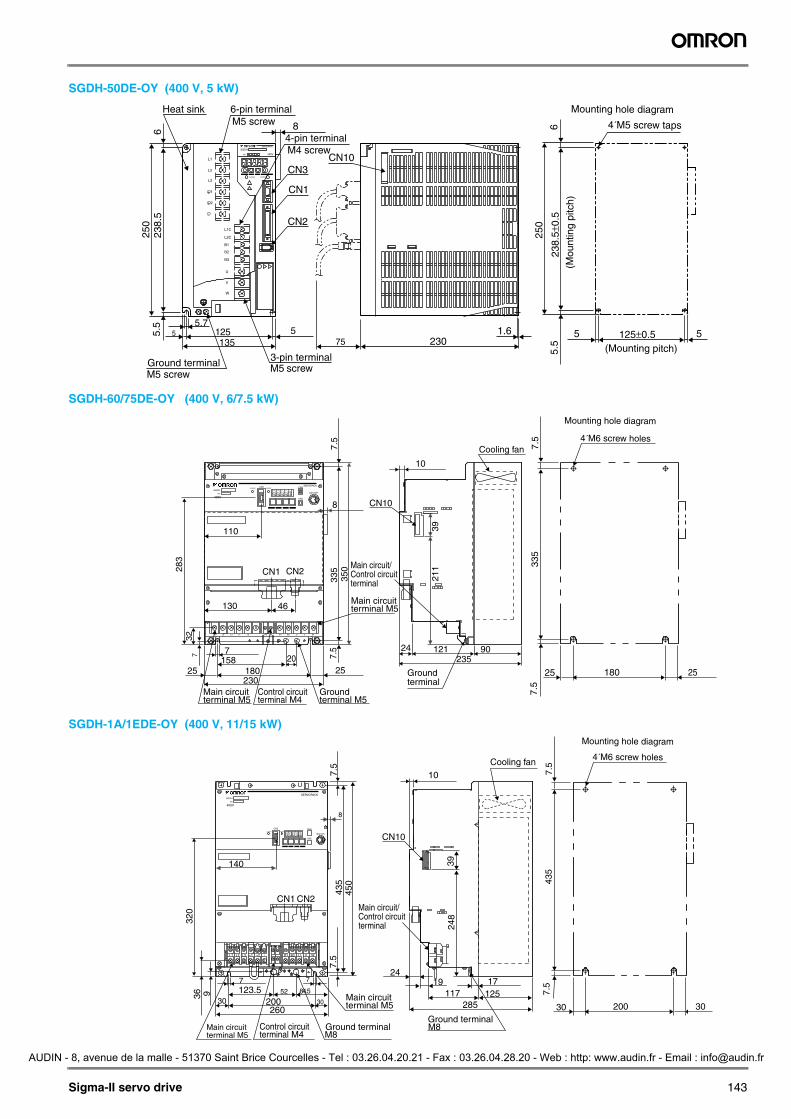
SGDH-50DE-OY (400 V, 5 kW)
SGDH-60/75DE-OY (400 V, 6/7.5 kW)
SGDH-1A/1EDE-OY (400 V, 11/15 kW)
CN2
CN3
4-pin terminalM4 screw
250
Heat sink 6-pin terminalM5 screw
75 230 1.6125
623
8.5
5.7
5.5
5 5
3-pin terminalM5 screw
135
CN1
8
CN10L1
L2
L2C
B1
B2
B3
U
V
W
L1C
L3
1+
2+
-
250
238.
5±0.
5
125±0.5
5.5
5 5
6
CHARGE POWER
(Mou
ntin
g pi
tch)
(Mounting pitch)
4´M5 screw taps
Mounting hole diagram
Ground terminalM5 screw
SERVOPACK
SGDH-
400VVer.
Cooling fan
10
39
24 121 90 235
Main circuit/Control circuitterminal
CN10
L1 L2 L3 +1 +2 - 24V 0V B1 B2 U V W
CN3 CN8
BATTERY
CHARGE POWER
CN1 CN2
335
7.5
7.5
350
46
8
7 32
28
3
7 158 20
25 180 230
CN5
110
130
211
25
335
7.5
7.5
180 25 25
Main circuitterminal M5
Main circuitterminal M5
Control circuitterminal M4
Groundterminal M5
Groundterminal
Mounting hole diagram
4´M6 screw holes
SGDH -
400VVer.
SERVOPACK
CN1 CN2
CN3POWER
CN8
CN5
BATTERCHARGE
SERVOPACK
140
9 36
320
7 7
123.5 52 84.5
30 200 260
8
7.5
7.5
435
450
Main circuitterminal M5
39
248
24 19 17
125 285
CN10
10 Cooling fan
117 30
435
7.5
7.5
200 30 30
L1 L2 L3 +1 +2 - B1 B2 U V W
Main circuitterminal M5 M8
Ground terminal M8Ground terminal
Control circuitterminal M4
Main circuit/Control circuitterminal
Mounting hole diagram
4´M6 screw holes
SGDH -
400VVer.
Y203-EN2-02-Katalog.book Seite 143 Mittwoch, 24. Mai 2006 2:22 14
AUDIN - 8, avenue de la malle - 51370 Saint Brice Courcelles - Tel : 03.26.04.20.21 - Fax : 03.26.04.28.20 - Web : http: www.audin.fr - Email : [email protected]

144 AC servo systems
SGDH-2BDE (400 V, 22 kW) SGDH-3ZDE (400 V, 30 kW)
SGDH-3GDE (400 V, 37 kW)
SGDH-4EDE / -5EDE (400 V, 45/55 kW)
+2- +1 L1/R L2/S L3/T U V W
CN3
CN1 CN2
CN6B
CN4
NS100
CN6A
Air
B2DW DC24P
400V
380V DVDU B1480
V460V
440V
0V
DC24N
4-Mounting holesfor M8 screw
OperatorConnectors
ControlConnectors
MainterminalswithM3.5 screw
MainterminalswithM8 screw
EarthterminalswithM8 screw
ControlterminalswithM4 screw
MainterminalswithM4 screw
459
12
57
12x4=485x8=40
6425 320
370
20 47(25)12
.547
512
.5
65
8 15
116
142
128152
215302306
348
Cooling fan
500
167107 7446.5
Approx. weight: 40 kgApprox. weight: 40 kg
4-Mounting holesfor M8 screw
OperatorConnectors
Controlconnectors
MainterminalswithM3.5 screw
MainterminalswithM8 screw
EarthterminalswithM8 screw
ControlterminalswithM4 screw
MainterminalswithM4 screw
459
151
12
10757 8x5=40
5225 320
370
20 47
(25)
500
475
12.5
65
8 15
142
116
152215
302128
306348
Cooling fan
MainterminalswithM5 screw
+2- +1 L1/R L2/S L3/T U V W
CN3
CN1 CN2
CN6B
CN4
NS100
CN6A
Air
480V
460V DU400
V0V
440V DWDV B1380
VDC24NB2 DC
24P
18614.5
12x2=24 46.5 74
12.5
24.5x8=19627x8=216
- +1 +2 L1/R L2/S L3/T U V W
1 2 3 4
CN1 CN2
CN3
DVDU380V
DB24 DW
DBON B1 B2480
V460V
400V
440V
DC24P
0V
DC24N
CN6B
CN4
CN6A
NS100
Approx. weight: 60 kg
Air4-Mounting holesfor M8 screw
OperatorConnectors
ControlConnectors
MainterminalswithM3.5 screw
MainterminalswithM5 screw
EarthterminalswithM8 screw
ControlterminalswithM3.5 screw
MainterminalswithM4 screw
259
215197
12x2=24
8x5=40
14.5
25 450500
40
8
(25)
56.5
475
12.5
65 17.5
70
149
ControlterminalswithM4 screw
25
46.5 74
MainterminalswithM10 screw
302306
348
116
142
128174
215
Cooling fan
12.5 589
12
45x8=360
294
- +1 +2 L1/R L2/S L3/T U V W
1 2 3 4
CN1 CN2
Air
CN3
DB24
DW DC24N
DV400V
460V
DC24P
480V
440V
380V
B2B1DBON
0V
DU
CN6B
CN4
CN6A
NS100
Approx. weight: 65 kg
4-Mounting holesfor M8 screw
Operatorconnectors
Controlconnectors
MainterminalswithM3.5 screw
MainterminalswithM10 screw
EarthterminalswithM8 screw
ControlterminalswithM3.5 screw
MainterminalswithM4 screw
639
35312
265
247
12x2=24
8x5=40
19
25 500550
40 25
8
(25)
56.5
475
12.5
65 17.5 11
614
2
128204
215302306
348
Cooling fan
12.5
122
19946.5 74
311
ControlterminalswithM4 screw
MainterminalswithM6 screw
45x8=360
Y203-EN2-02-Katalog.book Seite 144 Mittwoch, 24. Mai 2006 2:22 14
AUDIN - 8, avenue de la malle - 51370 Saint Brice Courcelles - Tel : 03.26.04.20.21 - Fax : 03.26.04.28.20 - Web : http: www.audin.fr - Email : [email protected]
Sigma-II servo drive 145
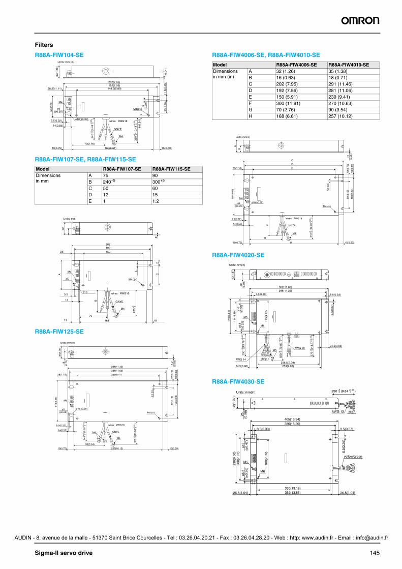
Filters
R88A-FIW104-SE
R88A-FIW107-SE, R88A-FIW115-SE
R88A-FIW125-SE
R88A-FIW4006-SE, R88A-FIW4010-SE
R88A-FIW4020-SE
R88A-FIW4030-SE
Model R88A-FIW107-SE R88A-FIW115-SEDimensionsin mm
A 75 90B 240+5 300+5 C 50 60 D 12 15E 1 1.2
32(1
.26)
56(2
.20)
33(1
.30)
6(0.
24)
5(0
.20)
265
(10.
43
)
+5
0+
0.20
0
240
(9.4
5
)
+5
0+
0.20
0
11.5
(0.4
5)1
(0.0
4)
202(7.95)192(7.56)
149.5(5.89)
168(6.61)
M4
GNYE
wires AWG16
M4(2×)
70(2.76)
19(0.75)
14(0.55)
5.5(0.22)
M4
φ5(φ0.20)
φ10(φ0.39)
15(0.59)
28.25(1.11)
Units: mm (in)
M4
GNYE
M4
φ5
φ10 wires AWG16
265
B
C
5
D
A32
E
+5
0
16819
14
5.5
15
70
15028
192202
M4(2×)
Units: mm
M4
M4
M5
5.5(0.22)
14(0.55)
19(0.75) 257(10.12) 15(0.59)
90(3.54)
28(1.10) 239(9.41)
281(11.06)
291(11.46)
GNYE
wires AWG16
355
(13.
98
)
35(1
.38)
118(
4.65
)
18(0
.71)
1.2
(0.0
5)
5(0.
20)
10(0
.39)
19(0
.75)
80(3
.15)
100(
3.94
)
+5
0+
0.02
0
245
(9.6
5
)
+0.
5 0
+0.
02 0
φ5(φ0.20)
φ10(φ0.39)
M4(4×)
Units: mm(in)
Model R88A-FIW4006-SE R88A-FIW4010-SEDimensionsin mm (in)
A 32 (1.26) 35 (1.38)B 16 (0.63) 18 (0.71)C 202 (7.95) 291 (11.46)D 192 (7.56) 281 (11.06)E 150 (5.91) 239 (9.41)F 300 (11.81) 270 (10.63)G 70 (2.76) 90 (3.54)H 168 (6.61) 257 (10.12)
M4
M4
GNYE
L1L2
L3
5.5(0.22)
14(0.55)
19(0.75) H 15(0.59)
G
28(1.10)
D
E
C
wires AWG16
310
(12.
20
)
A11
8(4.
65)
B
1.2
(0.0
5)
5(0.
20)
10(0
.39)
19(0
.75)
80(3
.15)
100(
3.94
)
+5
0+
0.20
0
F
φ5(φ0.20)
φ10(φ0.39)
M4(4×)
Units: mm(in)
M5
M5
M5
gb/gr238.5(9.39)
AWG 20
253(9.96)24.5(0.96)
AWG 14
7.5(0.30)
302(11.89)285(11.22)
40(1
.57)
20(0
.79)
370
(14.
57
)
+5
0+
0.20
0
350
(13.
78
)
+5
0+
0.20
0
580
(22.
83
)
+5
0+
0.20
0
φ10
(φ0.
39)
140(
5.51
)
114(
4.49
)
125(
4.92
)
φ5.5
(φ0.
22)
24.5(0.96)
8.5(0.33)
5.5(
0.22
)
Units: mm(in)
φ6.5
(φ0.
26)
200(
7.87
)
180(
7.09
)
8.5(0.33) 9.5(0.37)
M5AWG 12
6.5(
0.26
)
386(15.20)405(15.94)
230(
9.06
)50
(1.9
7)
25(0
.98)
φ12
(φ0.
47)
250 (9.84 )+5 0
+0.20 0
26.5(1.04) 26.5(1.04)
M6
M5
335(13.19)352(13.86)
yellow/green
Units: mm(in)
Y203-EN2-02-Katalog.book Seite 145 Mittwoch, 24. Mai 2006 2:22 14
AUDIN - 8, avenue de la malle - 51370 Saint Brice Courcelles - Tel : 03.26.04.20.21 - Fax : 03.26.04.28.20 - Web : http: www.audin.fr - Email : [email protected]

146 AC servo systems
Filters
R88A-FIW4055-SE
FN258-180-07
FN359-250-99
Digital operator
JUSP-OP02A-2
Regenerative resistor units DB resistor units
φ6.5
(φ0.
26)
φ12
(φ0.
47)
65(2
.56)
260(
10.2
4)
220(
8.66
)
6.5
(0.2
6)
200(
7.87
)
8.5(0.33)
26.5(1.04) 26.5(1.04)452(17.80)
435(17.13)
M6 M6 M5
3 × WIRE AWG6BLACK
WIRE AWG6YELLOW/GREEN M8
487(19.17) 9(0.35)
505(19.88)
32.5
(1.2
8)
370 (14.57 )+5 0
+0.20 0
Units: mm(in)
438
240
110 400
413
80
6.5
500
4
15
M10
50 mm2
2 (0.08) ×φ4.5 (0.18)mounting holes
125
(4.9
2)
135
(5.3
1)
63 (2.48)Units: mm (in)
18.5 (0.73)7 (0.28)50 (1.97)
YASKAWA
26 (1.02) (8)
(0.3
1)
39 (1.54)
29.5 (1.16)
Model W H D M1 M2 Approx. weight kg JUSP-RA18 220 350 92 180 335 4 JUSP-RA19 300 350 95 250 335 7 JUSP-RA12 259 500 348 200 485 14JUSP-RA13 259 500 348 200 485 14JUSP-RA14 484 500 348 425 485 20JUSP-RA15 484 500 348 425 485 21.5JUSP-RA16 484 500 348 425 485 23.5
HM2
M1 DW
Model H M2 Approx. weight kg JUSP-DB03 400 385 5 JUSP-DB04 400 385 6JUSP-DB05 400 385 6 JUSP-DB06 490 475 7
Ventilatingholes
259187
184
Wire lead-in hole(With 33 DIA, rubber bushing)
HM2
737.
5
Main circuit terminal
124
75
4-M5 MTG holesFront cover
62
Y203-EN2-02-Katalog.book Seite 146 Mittwoch, 24. Mai 2006 2:22 14
AUDIN - 8, avenue de la malle - 51370 Saint Brice Courcelles - Tel : 03.26.04.20.21 - Fax : 03.26.04.28.20 - Web : http: www.audin.fr - Email : [email protected]

Sigma-II servo drive 147
Single-phase, 230 VAC
*1 The time constant for the primary filter is 47 µs.*2 Connect when using an absolute encoder.*3 Used only with an absolute encoder.*4 Regenerative resistor can be connected between B1 and B2.*5 For types SGDH-08AE-S-OY and SGDH-15AE-S-OY, voltage is 220 to 230 VAC (+10% -15%).*6 TI stands for Texas Instruments Inc.
Installation
4
3
1
1
Amount of phase-S rotationSerial data outputApplicable line receiverSN75175 manufactured by Texas Instruments or the equivalent corresponding to MC3486
Connect shield to connector shell.
PG dividing ratio outputApplicable line receiverSN75175 manufactured by Texas Instruments or the equivalent corresponding to MC3486
Running output(ON when the motor speed exceeds the settings.)
Servo ready output(ON when ready)
Servo alarm output(OFF for an alarm)
Photocoupler outputMax. operating voltage:30 VDCMax. operating current: 50 mA DC
Speed coincidence detection(ON when speed coincides.)
Alarm code outputMax. operating voltage:30 VDCMax. operating current:20 mA DC
Servo ON(Servo ON when ON)
Reverse run prohibited(Prohibited when OFF)
Forward run prohibited(Prohibited when OFF)
Alarm reset(Reset when ON)
Reverse current limit(Limit when ON)
Forward current limit(Limit when ON)
P control(P control when ON)
SEN signal input∗2
Backup battery(2.8 to 4.5 V)
∗2
Position reference
Open-collector referencePower supply
Speed reference(±2 to ±10 V/rated motor speed)
Torque reference(±1 to ±10 V/rated torque)
Be sure toground
Be sure to prepare the end ofthe shielded wire properly
Optical encoder
Servo motor
Be sure to attach a surge suppressor to the excitationcoil of the magnetic contactor and relay
Alarm processingPowerOff
PowerONNoise filter
Single-Phase 200 to 230 VAC
SGDHServo drive
Y203-EN2-02-Katalog.book Seite 147 Mittwoch, 24. Mai 2006 2:22 14
AUDIN - 8, avenue de la malle - 51370 Saint Brice Courcelles - Tel : 03.26.04.20.21 - Fax : 03.26.04.28.20 - Web : http: www.audin.fr - Email : [email protected]
148 AC servo systems
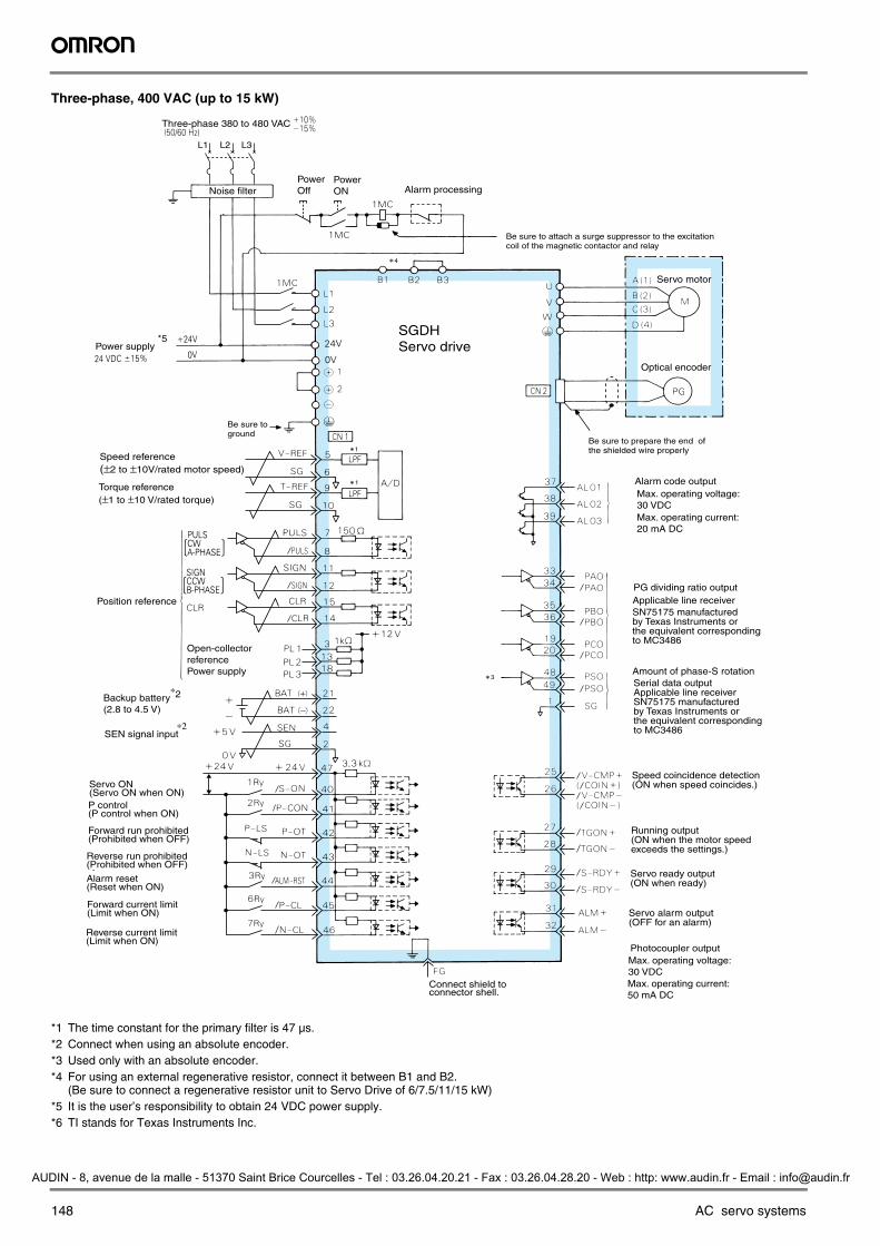
Three-phase, 400 VAC (up to 15 kW)
*1 The time constant for the primary filter is 47 µs.*2 Connect when using an absolute encoder.*3 Used only with an absolute encoder.*4 For using an external regenerative resistor, connect it between B1 and B2.
(Be sure to connect a regenerative resistor unit to Servo Drive of 6/7.5/11/15 kW)*5 It is the user’s responsibility to obtain 24 VDC power supply.*6 TI stands for Texas Instruments Inc.
L1 L2 L3
4
1
1
3
Be sure to prepare the end ofthe shielded wire properly
Optical encoder
Servo motor
Amount of phase-S rotationSerial data outputApplicable line receiverSN75175 manufactured by Texas Instruments or the equivalent corresponding to MC3486
PG dividing ratio outputApplicable line receiverSN75175 manufactured by Texas Instruments or the equivalent corresponding to MC3486
Running output(ON when the motor speed exceeds the settings.)
Servo ready output(ON when ready)
Servo alarm output(OFF for an alarm)
Photocoupler outputMax. operating voltage:30 VDCMax. operating current: 50 mA DC
Speed coincidence detection(ON when speed coincides.)
Alarm code outputMax. operating voltage:30 VDCMax. operating current:20 mA DC
Connect shield to connector shell.
Servo ON(Servo ON when ON)
Reverse run prohibited(Prohibited when OFF)
Forward run prohibited(Prohibited when OFF)
Alarm reset(Reset when ON)
Reverse current limit(Limit when ON)
Forward current limit(Limit when ON)
P control(P control when ON)
SEN signal input∗2
Backup battery(2.8 to 4.5 V)
∗2
Position reference
Open-collector referencePower supply
Speed reference(±2 to ±10V/rated motor speed)
Torque reference(±1 to ±10 V/rated torque)
Be sure toground
Be sure to attach a surge suppressor to the excitationcoil of the magnetic contactor and relay
Alarm processingPowerOff
PowerONNoise filter
Three-phase 380 to 480 VAC
Power supply*5
SGDHServo drive
Y203-EN2-02-Katalog.book Seite 148 Mittwoch, 24. Mai 2006 2:22 14
AUDIN - 8, avenue de la malle - 51370 Saint Brice Courcelles - Tel : 03.26.04.20.21 - Fax : 03.26.04.28.20 - Web : http: www.audin.fr - Email : [email protected]

Sigma-II servo drive 149
Three-phase, 400 VAC (from 22 kW to 55 kW)
*1 Prepresents twisted pair cable.
*2 Constant number at primary filter is 47ms.
*3 Connects when using absolute encoder.
*4 Effective when using 12-bit absolute encoder.
*5 Regenerative resistor unit (option) should be mounted externally.
*6 TI stands for Texas Instruments Inc.
Three-Phase 380 to 460VAC % (50/60Hz)
+10 –15
1MCCB
R S T
Noise filter
Power supply
OFF
ON
1MC
1MC
Speed reference
Torque reference(±1V to ± 10 V/rated torque)
Power supply for speed andtorque reference(max. output cunent: 30 mA DC)
Torque monitor(2V/100%)
Speed monitor
2V/1000 min-1
or1V/1000 min-1
CN1
A/D
*2LPF
*2
PULSCW
PhaseA
LPF
Alarm processing andmotor thermal processing
1MC
SUP
Correctly terminate endof shielded cable.
DB resistor unit(see DB intructions.)
Power ON/OF
DC reactor(normally short circuited)
(Attach surge suppressor to magneticcontactor and relays.)
Regenerativeresistor unit
N
50
5
6
9
10
7
8
11
12
13
14
21
22
4
2
47
40
41
43
42
44
46
45
2324
V-REF
SGP
T-REF
SG
+12V -12V
+12V
-12V
P
PULS
*PULSP
SIGN
*SIGNP
CLR
SEN
*CLR
SG
P
+5V
0V
BAT+
BAT–
P
P
P B2 B1 +1 +2
*5
L1/R
L2/S
L3/T
480V460V440V400V380V0V
SGDHServo drive
{Positionreference
Back-up battery *3
SEN Signal Input *3
Servo ON for 1Ry ON
P Control for 2Ry ON
Reverse drive disabled for N-LS open
Forward drive disabled for P-LS open
Alarm reset for 3Ry ON
Reverse current control ON for 6Ry ON
Forward current control ON for 7Ry is ON
2.8 to 4.5 V
SIGN
CLR
+24V +24V
1Ry
2Ry
N-LS
P-LS
6Ry
7Ry
3Ry
SV-ON
P-CON
N-OT
P-OT
N-CL
P-CL
ALM-RST
4.7kW
5mA
CCWPhaseB
+–
Servo ON
P control
Reverse drivedisabled
Reverse current
Control ON
Forward drivedisabled
Alarm reset
Forward current
Control ON
( )Alarm code output
Max. operational voltage: 30 VDCMax. operational current: 20 mADC
PG frequency division output line receiver (made by TI) SN75175, MC3486 or equivalent
line receiver (made by TI) SN75175, MC3486 or equivalent
ON at speed agreement
(ON at position complete)
TGON output(ON at exceeding the level)
Servo ready output(ON at servo ready)
Alarm output(OFF at alarm)
Photocoupler output Max. operational voltage: 30 VDC Max. operational current: 50 mADC
( )
( )FG
Connect to the shield.Connector case is also connected to FG.
Serial data Output*4 of the numberof rotations for phase S
0V
M
CN2 PG
S Motor
TRQ-M
U
V
W
16
VTG-M
ALO1
ALO2
ALO3
SG
V-CMP+ (COIN+)
PAO*PAO
PBO*PBO
PCO*PCO
PSO*PSO
17
37
38
39
3334
3536
1920
4849
25
26
27
2829
3031
32
DU
DV
DW
DBON
DB24
A1
1b
B
C
D
V-CMP– (COIN–)
TGON+
TGON–S-RDY+
S-RDY–ALM+
ALM–
M
Three-phase 380 to 460VAC % (50/60Hz)
+10–15
Motor for Fan
Opticalencoder
DU
DV
DW
DBON
DB24
DC24N24VDC
DC24P
Motor thermalprotector
Connect to the terminal whosevoltage is close to the powersupply voltage.
Y203-EN2-02-Katalog.book Seite 149 Mittwoch, 24. Mai 2006 2:22 14
AUDIN - 8, avenue de la malle - 51370 Saint Brice Courcelles - Tel : 03.26.04.20.21 - Fax : 03.26.04.28.20 - Web : http: www.audin.fr - Email : [email protected]
150 AC servo systems
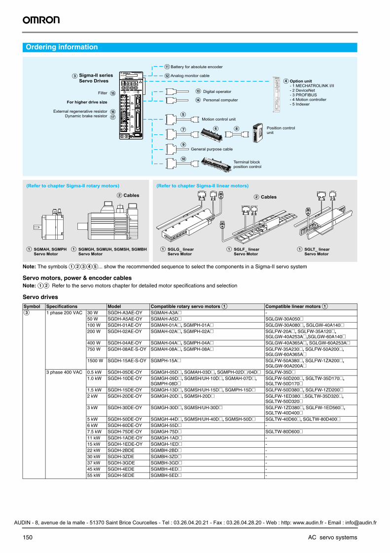
Ordering information
Note: The symbols ABCDE... show the recommended sequence to select the components in a Sigma-II servo system
Servo motors, power & encoder cablesNote: AB Refer to the servo motors chapter for detailed motor specifications and selection
Servo drives
Symbol Specifications Model Compatible rotary servo motors A Compatible linear motors AC 1 phase 200 VAC 30 W SGDH-A3AE-OY SGMAH-A3A@ -
50 W SGDH-A5AE-OY SGMAH-A5D@ SGLGW-30A050@100 W SGDH-01AE-OY SGMAH-01A@, SGMPH-01A@ SGLGW-30A080@, SGLGW-40A140@200 W SGDH-02AE-OY SGMAH-02A@, SGMPH-02A@ SGLFW-20A@, SGLFW-35A120@,
SGLGW-40A253A@,SGLGW-60A140@400 W SGDH-04AE-OY SGMAH-04A@, SGMPH-04A@ SGLGW-40A365A@, SGLGW-60A253A@750 W SGDH-08AE-S-OY SGMAH-08A@, SGMPH-08A@ SGLFW-35A230@, SGLFW-50A200@,
SGLGW-60A365A@1500 W SGDH-15AE-S-OY SGMPH-15A@ SGLFW-50A380@, SGLFW-1ZA200@,
SGLGW-90A200A@3 phase 400 VAC 0.5 kW SGDH-05DE-OY SGMGH-05D@, SGMAH-03D@, SGMPH-02D@/04D@ SGLFW-35D@
1.0 kW SGDH-10DE-OY SGMGH-09D@, SGMSH/UH-10D@, SGMAH-07D@, SGMPH-08D@
SGLFW-50D200@, SGLTW-35D170@, SGLTW-50D170@
1.5 kW SGDH-15DE-OY SGMGH-13D@, SGMSH/UH-15D@, SGMPH-15D@ SGLFW-50D380@, SGLFW-1ZD200@2 kW SGDH-20DE-OY SGMGH-20D@, SGMSH-20D@ SGLFW-1ED380@,SGLTW-35D320@,
SGLTW-50D320@3 kW SGDH-30DE-OY SGMGH-30D@, SGMSH/UH-30D@ SGLFW-1ZD380@, SGLFW-1ED560@,
SGLTW-40D400@5 kW SGDH-50DE-OY SGMGH-44D@, SGMSH/UH-40D@, SGMSH-50D@ SGLTW-40D60@, SGLTW-80D400@6 kW SGDH-60DE-OY SGMGH-55D@ -7.5 kW SGDH-75DE-OY SGMGH-75D@ SGLTW-80D600@11 kW SGDH-1ADE-OY SGMGH-1AD@ -15 kW SGDH-1EDE-OY SGMGH-1ED@ -22 kW SGDH-2BDE SGMBH-2BD@ -30 kW SGDH-3ZDE SGMBH-3ZD@ -37 kW SGDH-3GDE SGMBH-3GD@ -45 kW SGDH-4EDE SGMBH-4ED@ -55 kW SGDH-5EDE SGMBH-5ED@ -
M
L
Q
O
P
Cables Cables
A
CHARGE POWER
SERVOPACK
SGDH-
200VVer.
CN3
CN1
CN2
F H
J
I
E
G
D C
B
A A
B
A A
K
SGMGH, SGMUH, SGMSH, SGMBH Servo Motor
(Refer to chapter Sigma-II linear motors)
SGMAH, SGMPHServo Motor
Position controlunit
Terminal block position control
General purpose cable
Motion control unit
Digital operator
Option unit- 1 MECHATROLINK I/II- 2 DeviceNet- 3 PROFIBUS- 4 Motion controller- 5 Indexer
Battery for absolute encoder
Analog monitor cable
Filter
For higher drive size
External regenerative resistorDynamic brake resistor
Sigma-II series
Servo Drives
SGLT_ linearServo Motor
SGLG_ linearServo Motor
SGLF_ linear Servo Motor
(Refer to chapter Sigma-II rotary motors)
Personal computer
NS115
SW1
SW2
AR
CN6A
CN6B
CN4
Y203-EN2-02-Katalog.book Seite 150 Mittwoch, 24. Mai 2006 2:22 14
AUDIN - 8, avenue de la malle - 51370 Saint Brice Courcelles - Tel : 03.26.04.20.21 - Fax : 03.26.04.28.20 - Web : http: www.audin.fr - Email : [email protected]

Sigma-II servo drive 151
Option units (for CN10)
Note: D Refer to the servo drive option unit chapter for detailed specifications and selection
Control cables (for CN1)
Symbol Name Model
D 1.5 axis advanced motion controller with host link interface R88A-MCW151-E1.5 axis advanced motion controller with DeviceNet interface R88A-MCW151-DRT-EMECHATROLINK-I interface unit JUSP-NS100MECHATROLINK-II interface unit JUSP-NS115DeviceNet interface unit with positioning fuctionality JUSP-NS300PROFIBUS-DP interface unit with positioning fuctionality JUSP-NS500Indexer unit. Versatile point-to-point positioning JUSP-NS600
Symbol Description Connect to Model
E Control cable(1 axis)
Motion control units CS1W-MC221CS1W-MC421C200H-MC221
1 m R88A-CPW001M1 2 m R88A-CPW002M13 m R88A-CPW003M15 m R88A-CPW005M1
Control cable(2 axis)
Motion control units CS1W-MC221CS1W-MC421C200H-MC221
1 m R88A-CPW001M22 m R88A-CPW002M23 m R88A-CPW003M25 m R88A-CPW005M2
Terminal block (4 axes)
Motion control unit C200HW-MC402-E
- R88A-TC04-E
Servo drive connecting cable (1 axis)
1 m R88A-CMUK001J3-E2
PLC unit control cables (4 axes)
1 m R88A-CMX001S-E1 m R88A-CMX001J1-E
F Servo relay unit CS1W-NC1@3, CJ1W-NC1@3, or C200HW-NC113 Position control unit
XW2B-20J6-1B (1 axis)
CS1W-NC2@3/4@3, CJ1W-NC2@3/4@3, or C200HW-NC213/413 position control unit
XW2B-40J6-2B (2 axes)
CQM1H-PLB21CQM1-CPU43
XW2B-20J6-3B (1 axis)
CJ1M-CPU22/23 XW2B-20J6-8A (1 axis)XW2B-40J6-9A (2 axes)
G Cable to servo drive Servo relay units XW2B-@0J6-@B 1 m XW2Z-100J-B42 m XW2Z-200J-B4
H Position control unit connecting cable
C200H-NC112 0.5 m XW2Z-050J-A11 m XW2Z-100J-A1
C200H-NC211 0.5 m XW2Z-050J-A21 m XW2Z-100J-A2
CQM1-CPU43-V1 and CQM1H-PLB21 0.5 m XW2Z-050J-A31 m XW2Z-100J-A3
CS1W-NC113 and C200HW-NC113 0.5 m XW2Z-050J-A61 m XW2Z-100J-A6
CS1W-NC213/413 and C200HW-NC213/413
0.5 m XW2Z-050J-A71 m XW2Z-100J-A7
CS1W-NC133 0.5 m XW2Z-050J-A101 m XW2Z-100J-A10
CS1W-NC233/433 0.5 m XW2Z-050J-A111 m XW2Z-100J-A11
CJ1W-NC113 0.5 m XW2Z-050J-A141 m XW2Z-100J-A14
CJ1W-NC213/413 0.5 m XW2Z-050J-A151 m XW2Z-100J-A15
CJ1W-NC133 0.5 m XW2Z-050J-A181 m XW2Z-100J-A18
CJ1W-NC233/433 0.5 m XW2Z-050J-A191 m XW2Z-100J-A19
CJ1M-CPU22/23 0.5 m XW2Z-050J-A271 m XW2Z-100J-A27
I Control cable For general purpose controllers 1 m R88A-CPW001Sor JZSP-CKI01-1
2 m R88A-CPW002Sor JZSP-CKI01-1
J Relay terminal block cable General purpose controller 1 m R88A-CTW001N2 m R88A-CTW002N
Relay terminal block - XW2B-50G5
Y203-EN2-02-Katalog.book Seite 151 Mittwoch, 24. Mai 2006 2:22 14
AUDIN - 8, avenue de la malle - 51370 Saint Brice Courcelles - Tel : 03.26.04.20.21 - Fax : 03.26.04.28.20 - Web : http: www.audin.fr - Email : [email protected]
152 AC servo systems
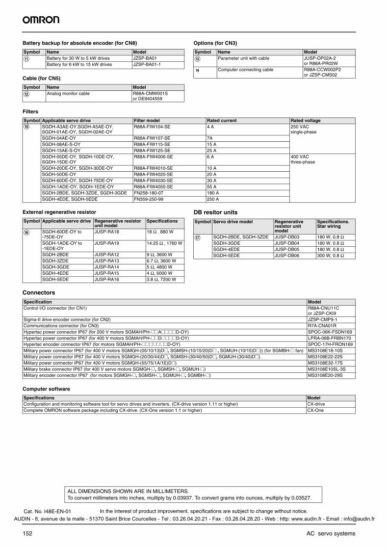
Battery backup for absolute encoder (for CN8)
Cable (for CN5)
Options (for CN3)
Filters
External regenerative resistor DB resitor units
Connectors
Computer software
Symbol Name Model
K Battery for 30 W to 5 kW drives JZSP-BA01Battery for 6 kW to 15 kW drives JZSP-BA01-1
Symbol Name Model
L Analog monitor cable R88A-CMW001Sor DE9404559
Symbol Name Model
M Parameter unit with cable JUSP-OP02A-2or R88A-PR02W
N Computer connecting cable R88A-CCW002P2or JZSP-CMS02
Symbol Applicable servo drive Filter model Rated current Rated voltageO SGDH-A3AE-OY,SGDH-A5AE-OY,
SGDH-01AE-OY, SGDH-02AE-OYR88A-FIW104-SE 4 A 250 VAC
single-phaseSGDH-04AE-OY R88A-FIW107-SE 7ASGDH-08AE-S-OY R88A-FIW115-SE 15 ASGDH-15AE-S-OY R88A-FIW125-SE 25 ASGDH-05DE-OY, SGDH-10DE-OY,SGDH-15DE-OY
R88A-FIW4006-SE 6 A 400 VACthree-phase
SGDH-20DE-OY, SGDH-30DE-OY R88A-FIW4010-SE 10 ASGDH-50DE-OY R88A-FIW4020-SE 20 ASGDH-60DE-OY, SGDH-75DE-OY R88A-FIW4030-SE 30 ASGDH-1ADE-OY, SGDH-1EDE-OY R88A-FIW4055-SE 55 ASGDH-2BDE, SGDH-3ZDE, SGDH-3GDE FN258-180-07 180 ASGDH-4EDE, SGDH-5EDE FN359-250-99 250 A
Symbol Applicable servo drive Regenerative resistor unit model
Specifications
P SGDH-60DE-OY to -75DE-OY
JUSP-RA18 18 Ω , 880 W
SGDH-1ADE-OY to -1EDE-OY
JUSP-RA19 14.25 Ω , 1760 W
SGDH-2BDE JUSP-RA12 9 Ω, 3600 WSGDH-3ZDE JUSP-RA13 6.7 Ω, 3600 WSGDH-3GDE JUSP-RA14 5 Ω, 4800 WSGDH-4EDE JUSP-RA15 4 Ω, 6000 WSGDH-5EDE JUSP-RA16 3.8 Ω, 7200 W
Symbol Servo drive model Regenerative resistor unit model
Specifications. Star wiring
Q SGDH-2BDE, SGDH-3ZDE JUSP-DB03 180 W, 0.8 ΩSGDH-3GDE JUSP-DB04 180 W, 0.8 ΩSGDH-4EDE JUSP-DB05 180 W, 0.8 ΩSGDH-5EDE JUSP-DB06 300 W, 0.8 Ω
Specification ModelControl I/O connector (for CN1) R88A-CNU11C
or JZSP-CKI9 Sigma-II drive encoder connector (for CN2) JZSP-CMP9-1Communications connector (for CN3) R7A-CNA01RHypertac power connector IP67 (for 200 V motors SGMAH/PH-@@A@@@@D-OY) SPOC-06K-FSDN169Hypertac power connector IP67 (for 400 V motors SGMAH/PH-@@D@@@@D-OY) LPRA-06B-FRBN170Hypertac encoder connector IP67 (for motors SGMAH/PH-@@@@@@@D-OY) SPOC-17H-FRON169Military power connector IP67 (for 400 V motors SGMGH-(05/10/13)D@, SGMSH-(10/15/20)D@ , SGMUH-(10/15)D@)) (for SGMBH-@ fan) MS3108E18-10SMilitary power connector IP67 (for 400 V motors SGMGH-(20/30/44)D@, SGMSH-(30/40/50)D@, SGMUH-(30/40)D@) MS3108E22-22SMilitary power connector IP67 (for 400 V motors SGMGH-(55/75/1A/1E)D@) MS3108E32-17SMilitary brake connector IP67 (for 400 V servo motors SGMGH-@, SGMSH-@, SGMUH-@) MS3108E10SL-3SMilitary encoder connector IP67 (for motors SGMGH-@, SGMSH-@, SGMUH-@, SGMBH-@) MS3108E20-29S
Specifications ModelConfiguration and monitoring software tool for servo drives and inverters. (CX-drive version 1.11 or higher) CX-driveComplete OMRON software package including CX-drive. (CX-One version 1.1 or higher) CX-One
In the interest of product improvement, specifications are subject to change without notice.
ALL DIMENSIONS SHOWN ARE IN MILLIMETERS.To convert millimeters into inches, multiply by 0.03937. To convert grams into ounces, multiply by 0.03527.
Cat. No. I48E-EN-01
Y203-EN2-02-Katalog.book Seite 152 Mittwoch, 24. Mai 2006 2:22 14
AUDIN - 8, avenue de la malle - 51370 Saint Brice Courcelles - Tel : 03.26.04.20.21 - Fax : 03.26.04.28.20 - Web : http: www.audin.fr - Email : [email protected]
Top Related