


Languages
Pages
Legal

Service & Maintenance Manual
Model260MRT
3121801
April 19, 2013

INTRODUCTION - MAINTENANCE SAFETY PRECAUTIONS
SECTION A. INTRODUCTION - MAINTENANCE SAFETY PRECAUTIONS
A GENERAL
This section contains the general safety precautionswhich must be observed during maintenance of theaerial platform. It is of utmost importance that main-tenance personnel pay strict attention to these warn-ings and precautions to avoid possible injury tothemselves or others, or damage to the equipment.A maintenance program must be followed to ensurethat the machine is safe to operate.
MODIFICATION OF THE MACHINE WITHOUT CERTIFI-CATION BY A RESPONSIBLE AUTHORITY THAT THEMACHINE IS AT LEAST AS SAFE AS ORIGINALLYMANUFACTURED, IS A SAFETY VIOLATION.
The specific precautions to be observed duringmaintenance are inserted at the appropriate point inthe manual. These precautions are, for the mostpart, those that apply when servicing hydraulic andlarger machine component parts.
Your safety, and that of others, is the first consider-ation when engaging in the maintenance of equip-ment. Always be conscious of weight. Never attemptto move heavy parts without the aid of a mechanicaldevice. Do not allow heavy objects to rest in anunstable position. When raising a portion of theequipment, ensure that adequate support is pro-vided.
SINCE THE MACHINE MANUFACTURER HAS NODIRECT CONTROL OVER THE FIELD INSPECTIONAND MAINTENANCE, SAFETY IN THIS AREA RESPON-SIBILITY OF THE OWNER/OPERATOR.
B HYDRAULIC SYSTEM SAFETY
It should be noted that the machines hydraulic sys-tems operate at extremely high potentially danger-ous pressures. Every effort should be made torelieve any system pressure prior to disconnectingor removing any portion of the system.
Relieve system pressure by cycling the applicablecontrol several times with the engine stopped andignition on, to direct any line pressure back into thereservoir. Pressure feed lines to system componentscan then be disconnected with minimal fluid loss.
C MAINTENANCE
FAILURE TO COMPLY WITH SAFETY PRECAUTIONSLISTED IN THIS SECTION MAY RESULT IN MACHINEDAMAGE, PERSONNEL INJURY OR DEATH AND IS ASAFETY VIOLATION.
• NO SMOKING IS MANDATORY. NEVER REFUEL DUR-ING ELECTRICAL STORMS. ENSURE THAT FUEL CAPIS CLOSED AND SECURE AT ALL OTHER TIMES.
• REMOVE ALL RINGS, WATCHES AND JEWELRYWHEN PERFORMING ANY MAINTENANCE.
• DO NOT WEAR LONG HAIR UNRESTRAINED, ORLOOSE-FITTING CLOTHING AND NECKTIES WHICHARE APT TO BECOME CAUGHT ON OR ENTANGLEDIN EQUIPMENT.
• OBSERVE AND OBEY ALL WARNINGS AND CAU-TIONS ON MACHINE AND IN SERVICE MANUAL.
• KEEP OIL, GREASE, WATER, ETC. WIPED FROMSTANDING SURFACES AND HAND HOLDS.
• USE CAUTION WHEN CHECKING A HOT, PRESSUR-IZED COOLANT SYSTEM.
• NEVER WORK UNDER AN ELEVATED BOOM UNTILBOOM HAS BEEN SAFELY RESTRAINED FROM ANYMOVEMENT BY BLOCKING OR OVERHEAD SLING, ORBOOM SAFETY PROP HAS BEEN ENGAGED.
• BEFORE MAKING ADJUSTMENTS, LUBRICATING ORPERFORMING ANY OTHER MAINTENANCE, SHUTOFF ALL POWER CONTROLS.
• BATTERY SHOULD ALWAYS BE DISCONNECTED DUR-ING REPLACEMENT OF ELECTRICAL COMPONENTS.
• KEEP ALL SUPPORT EQUIPMENT AND ATTACH-MENTS STOWED IN THEIR PROPER PLACE.
• USE ONLY APPROVED, NONFLAMMABLE CLEANINGSOLVENTS.
REVISION LOG
3121801 – JLG Lift – a

INTRODUCTION - MAINTENANCE SAFETY PRECAUTIONS
Original Issue - April 13, 2000
Revised - January 24, 2002
Revised - April 22, 2004
Revised - July 3, 2006
Revised - August 30, 2006
Revised - October 11, 2007
Revised - April 28, 2008
Revised - December 19, 2008
Revised - October 20, 2011
Revised - April 19, 2013
b – JLG Lift – 3121801

TABLE OF CONTENTS
TABLE OF CONTENTS
SUBJECT - SECTION, PARAGRAPH PAGE NO.
SECTION A - INTRODUCTION - MAINTENANCE SAFETY PRECAUTIONS
A.A General . . . . . . . . . . . . . . . . . . . . . . . . . . . . . . . . . . . . . . . . . . . . . . . . . . . . . . . . . . . . . . . . . . . . . .1-aA.B Hydraulic System Safety . . . . . . . . . . . . . . . . . . . . . . . . . . . . . . . . . . . . . . . . . . . . . . . . . . . . . . . . .1-aA.C Maintenance . . . . . . . . . . . . . . . . . . . . . . . . . . . . . . . . . . . . . . . . . . . . . . . . . . . . . . . . . . . . . . . . . .1-a
SECTION 1 - SPECIFICATIONS
1.1 Specifications . . . . . . . . . . . . . . . . . . . . . . . . . . . . . . . . . . . . . . . . . . . . . . . . . . . . . . . . . . . . . . . . .1-11.2 Capacities . . . . . . . . . . . . . . . . . . . . . . . . . . . . . . . . . . . . . . . . . . . . . . . . . . . . . . . . . . . . . . . . . . . .1-11.3 Component Data . . . . . . . . . . . . . . . . . . . . . . . . . . . . . . . . . . . . . . . . . . . . . . . . . . . . . . . . . . . . . . .1-11.4 Lubrication. . . . . . . . . . . . . . . . . . . . . . . . . . . . . . . . . . . . . . . . . . . . . . . . . . . . . . . . . . . . . . . . . . . .1-21.5 Lubrication Specifications . . . . . . . . . . . . . . . . . . . . . . . . . . . . . . . . . . . . . . . . . . . . . . . . . . . . . . . .1-21.6 Cylinder Specifications . . . . . . . . . . . . . . . . . . . . . . . . . . . . . . . . . . . . . . . . . . . . . . . . . . . . . . . . . .1-31.7 Pressure Settings . . . . . . . . . . . . . . . . . . . . . . . . . . . . . . . . . . . . . . . . . . . . . . . . . . . . . . . . . . . . . .1-31.8 Limit Switches . . . . . . . . . . . . . . . . . . . . . . . . . . . . . . . . . . . . . . . . . . . . . . . . . . . . . . . . . . . . . . . . .1-31.9 Major Component Weights . . . . . . . . . . . . . . . . . . . . . . . . . . . . . . . . . . . . . . . . . . . . . . . . . . . . . . .1-31.10 Critical Stability Weights . . . . . . . . . . . . . . . . . . . . . . . . . . . . . . . . . . . . . . . . . . . . . . . . . . . . . . . . .1-31.11 Serial Number Locations. . . . . . . . . . . . . . . . . . . . . . . . . . . . . . . . . . . . . . . . . . . . . . . . . . . . . . . . .1-4
SECTION 2 - PROCEDURES
2.1 General . . . . . . . . . . . . . . . . . . . . . . . . . . . . . . . . . . . . . . . . . . . . . . . . . . . . . . . . . . . . . . . . . . . . . .2-12.2 Servicing and Maintenance Guidelines . . . . . . . . . . . . . . . . . . . . . . . . . . . . . . . . . . . . . . . . . . . . .2-12.3 Lubrication Information . . . . . . . . . . . . . . . . . . . . . . . . . . . . . . . . . . . . . . . . . . . . . . . . . . . . . . . . . .2-22.4 Cylinders - Theory of Operation . . . . . . . . . . . . . . . . . . . . . . . . . . . . . . . . . . . . . . . . . . . . . . . . . . .2-32.5 Valves - Theory of Operation. . . . . . . . . . . . . . . . . . . . . . . . . . . . . . . . . . . . . . . . . . . . . . . . . . . . . .2-32.6 Component Functional Description . . . . . . . . . . . . . . . . . . . . . . . . . . . . . . . . . . . . . . . . . . . . . . . .2-42.7 Wear Pads . . . . . . . . . . . . . . . . . . . . . . . . . . . . . . . . . . . . . . . . . . . . . . . . . . . . . . . . . . . . . . . . . . . .2-42.8 Cylinder Checking Procedures . . . . . . . . . . . . . . . . . . . . . . . . . . . . . . . . . . . . . . . . . . . . . . . . . . . .2-42.9 Lift Cylinder Removal and Installation. . . . . . . . . . . . . . . . . . . . . . . . . . . . . . . . . . . . . . . . . . . . . . .2-52.10 Cylinder Repair . . . . . . . . . . . . . . . . . . . . . . . . . . . . . . . . . . . . . . . . . . . . . . . . . . . . . . . . . . . . . . . .2-82.11 Steer Cylinder Repair . . . . . . . . . . . . . . . . . . . . . . . . . . . . . . . . . . . . . . . . . . . . . . . . . . . . . . . . . . .2-132.12 Limit Switch Adjustment . . . . . . . . . . . . . . . . . . . . . . . . . . . . . . . . . . . . . . . . . . . . . . . . . . . . . . . . .2-152.13 Pressure Setting Procedures . . . . . . . . . . . . . . . . . . . . . . . . . . . . . . . . . . . . . . . . . . . . . . . . . . . . .2-152.14 Drive Pump Start-up Procedure . . . . . . . . . . . . . . . . . . . . . . . . . . . . . . . . . . . . . . . . . . . . . . . . . . .2-212.15 Automatic Choke - Field Adjustment (DF-750) . . . . . . . . . . . . . . . . . . . . . . . . . . . . . . . . . . . . . . . .2-222.16 Joystick Controller . . . . . . . . . . . . . . . . . . . . . . . . . . . . . . . . . . . . . . . . . . . . . . . . . . . . . . . . . . . . .2-232.17 Tilt Sensor . . . . . . . . . . . . . . . . . . . . . . . . . . . . . . . . . . . . . . . . . . . . . . . . . . . . . . . . . . . . . . . . . . . .2-252.18 Calibrations . . . . . . . . . . . . . . . . . . . . . . . . . . . . . . . . . . . . . . . . . . . . . . . . . . . . . . . . . . . . . . . . . . .2-272.19 Electronic Control System. . . . . . . . . . . . . . . . . . . . . . . . . . . . . . . . . . . . . . . . . . . . . . . . . . . . . . . .2-292.20 Flash Codes and Descriptions . . . . . . . . . . . . . . . . . . . . . . . . . . . . . . . . . . . . . . . . . . . . . . . . . . .2-332.21 Machine Model Adjustment . . . . . . . . . . . . . . . . . . . . . . . . . . . . . . . . . . . . . . . . . . . . . . . . . . . . . .2-392.22 Machine Configuration Programming Information . . . . . . . . . . . . . . . . . . . . . . . . . . . . . . . . . . . . .2-402.23 Preventive Maintenance and Inspection Schedule. . . . . . . . . . . . . . . . . . . . . . . . . . . . . . . . . . . . .2-41
SECTION 3 - GENERAL ELECTRICAL INFORMATION & SCHEMATICS
3.1 General . . . . . . . . . . . . . . . . . . . . . . . . . . . . . . . . . . . . . . . . . . . . . . . . . . . . . . . . . . . . . . . . . . . . . .3-13.2 Multimeter Basics . . . . . . . . . . . . . . . . . . . . . . . . . . . . . . . . . . . . . . . . . . . . . . . . . . . . . . . . . . . . . .3-13.3 Applying Silicone Dielectric Compound To Amp Connectors . . . . . . . . . . . . . . . . . . . . . . . . . . . .3-53.4 Working With Deutsch Connectors. . . . . . . . . . . . . . . . . . . . . . . . . . . . . . . . . . . . . . . . . . . . . . . . .3-103.5 Switches . . . . . . . . . . . . . . . . . . . . . . . . . . . . . . . . . . . . . . . . . . . . . . . . . . . . . . . . . . . . . . . . . . . . .3-123.6 Troubleshooting . . . . . . . . . . . . . . . . . . . . . . . . . . . . . . . . . . . . . . . . . . . . . . . . . . . . . . . . . . . . . . .3-13
3121801 – JLG Lift – i

TABLE OF CONTENTS
LIST OF FIGURES
FIGURE NO. TITLE PAGE NO.
1-1. Serial Number Location. . . . . . . . . . . . . . . . . . . . . . . . . . . . . . . . . . . . . . . . . . . . . . . . . . . . . . . . . .1-41-2. Lubrication Diagram . . . . . . . . . . . . . . . . . . . . . . . . . . . . . . . . . . . . . . . . . . . . . . . . . . . . . . . . . . . .1-51-3. Operating Temperature Specifications - Kubota . . . . . . . . . . . . . . . . . . . . . . . . . . . . . . . . . . . . . .1-61-4. Torque Chart - (In/Lb - Ft/Lb). (For ASTM Fasteners) . . . . . . . . . . . . . . . . . . . . . . . . . . . . . . . . . .1-71-5. Torque Chart (Metric Conversion) - (For ASTM Fasteners) . . . . . . . . . . . . . . . . . . . . . . . . . . . . . .1-81-6. Torque Chart - (N, m) - (For Metric Class Fasteners). . . . . . . . . . . . . . . . . . . . . . . . . . . . . . . . . . .1-92-1. Arms and Platform Positioning and Support, Cylinder Repair . . . . . . . . . . . . . . . . . . . . . . . . . . . .2-62-2. Lift Cylinder . . . . . . . . . . . . . . . . . . . . . . . . . . . . . . . . . . . . . . . . . . . . . . . . . . . . . . . . . . . . . . . . . . .2-72-3. Cylinder Barrel Support. . . . . . . . . . . . . . . . . . . . . . . . . . . . . . . . . . . . . . . . . . . . . . . . . . . . . . . . . .2-82-4. Capscrew Removal . . . . . . . . . . . . . . . . . . . . . . . . . . . . . . . . . . . . . . . . . . . . . . . . . . . . . . . . . . . . .2-82-5. Cylinder Rod Support . . . . . . . . . . . . . . . . . . . . . . . . . . . . . . . . . . . . . . . . . . . . . . . . . . . . . . . . . . .2-82-6. Tapered Bushing Removal . . . . . . . . . . . . . . . . . . . . . . . . . . . . . . . . . . . . . . . . . . . . . . . . . . . . . . .2-92-7. Rod Seal Installation . . . . . . . . . . . . . . . . . . . . . . . . . . . . . . . . . . . . . . . . . . . . . . . . . . . . . . . . . . . .2-102-8. Wiper Seal Installation. . . . . . . . . . . . . . . . . . . . . . . . . . . . . . . . . . . . . . . . . . . . . . . . . . . . . . . . . . .2-102-9. Installation of Head Seal Kit . . . . . . . . . . . . . . . . . . . . . . . . . . . . . . . . . . . . . . . . . . . . . . . . . . . . . .2-102-10. Piston Seal Kit Installation . . . . . . . . . . . . . . . . . . . . . . . . . . . . . . . . . . . . . . . . . . . . . . . . . . . . . . . .2-112-11. Tapered Bushing Installation . . . . . . . . . . . . . . . . . . . . . . . . . . . . . . . . . . . . . . . . . . . . . . . . . . . . .2-112-12. Seating the Tapered Bearing . . . . . . . . . . . . . . . . . . . . . . . . . . . . . . . . . . . . . . . . . . . . . . . . . . . . .2-112-13. Poly-Pak Piston Seal Installation. . . . . . . . . . . . . . . . . . . . . . . . . . . . . . . . . . . . . . . . . . . . . . . . . . .2-122-14. Rod Assembly Installation. . . . . . . . . . . . . . . . . . . . . . . . . . . . . . . . . . . . . . . . . . . . . . . . . . . . . . . .2-122-15. Steer Cylinder Assembly. . . . . . . . . . . . . . . . . . . . . . . . . . . . . . . . . . . . . . . . . . . . . . . . . . . . . . . . .2-162-16. Leveling Jack Assembly - (Prior to S/N 105371) . . . . . . . . . . . . . . . . . . . . . . . . . . . . . . . . . . . . . .2-172-17. Leveling Jack Assembly - (S/N 105371to S/N 141689) . . . . . . . . . . . . . . . . . . . . . . . . . . . . . . . . .2-182-18. Leveling Jack Assembly - (S/N 141689 to Present) . . . . . . . . . . . . . . . . . . . . . . . . . . . . . . . . . . . .2-192-19. Valve Components . . . . . . . . . . . . . . . . . . . . . . . . . . . . . . . . . . . . . . . . . . . . . . . . . . . . . . . . . . . . .2-202-20. Automatic Choke Adjustment (DF-750) . . . . . . . . . . . . . . . . . . . . . . . . . . . . . . . . . . . . . . . . . . . . .2-222-21. Joystick Controller - (JLG P/N 1600308) . . . . . . . . . . . . . . . . . . . . . . . . . . . . . . . . . . . . . . . . . . . .2-232-22. Joystick Controller - (JLG P/N 1600403) . . . . . . . . . . . . . . . . . . . . . . . . . . . . . . . . . . . . . . . . . . . .2-242-23. Tilt Sensor Location. . . . . . . . . . . . . . . . . . . . . . . . . . . . . . . . . . . . . . . . . . . . . . . . . . . . . . . . . . . . .2-252-24. Tilt Sensor Removal . . . . . . . . . . . . . . . . . . . . . . . . . . . . . . . . . . . . . . . . . . . . . . . . . . . . . . . . . . . .2-252-25. Tilt Sensor Location. . . . . . . . . . . . . . . . . . . . . . . . . . . . . . . . . . . . . . . . . . . . . . . . . . . . . . . . . . . . .2-262-26. Tilt Sensor Removal . . . . . . . . . . . . . . . . . . . . . . . . . . . . . . . . . . . . . . . . . . . . . . . . . . . . . . . . . . . .2-262-27. Hand Held Analyzer . . . . . . . . . . . . . . . . . . . . . . . . . . . . . . . . . . . . . . . . . . . . . . . . . . . . . . . . . . . .2-292-28. Analyzer Flow Chart - Sheet 1 of 4 . . . . . . . . . . . . . . . . . . . . . . . . . . . . . . . . . . . . . . . . . . . . . . . . .2-352-29. Analyzer Flow Chart - Sheet 2 of 4 . . . . . . . . . . . . . . . . . . . . . . . . . . . . . . . . . . . . . . . . . . . . . . . . .2-362-30. Analyzer Flow Chart - Sheet 3 of 4 . . . . . . . . . . . . . . . . . . . . . . . . . . . . . . . . . . . . . . . . . . . . . . . . .2-372-31. Analyzer Flow Chart - Sheet 4 of 4 . . . . . . . . . . . . . . . . . . . . . . . . . . . . . . . . . . . . . . . . . . . . . . . . .2-383-1. Voltage Measurement (DC). . . . . . . . . . . . . . . . . . . . . . . . . . . . . . . . . . . . . . . . . . . . . . . . . . . . . . .3-23-2. Resistance Measurement . . . . . . . . . . . . . . . . . . . . . . . . . . . . . . . . . . . . . . . . . . . . . . . . . . . . . . . .3-23-3. Continuity Measurement . . . . . . . . . . . . . . . . . . . . . . . . . . . . . . . . . . . . . . . . . . . . . . . . . . . . . . . . .3-33-4. Current Measurement (DC). . . . . . . . . . . . . . . . . . . . . . . . . . . . . . . . . . . . . . . . . . . . . . . . . . . . . . .3-33-5. AMP Connector . . . . . . . . . . . . . . . . . . . . . . . . . . . . . . . . . . . . . . . . . . . . . . . . . . . . . . . . . . . . . . . .3-53-6. Connector Assembly (1 of 4) . . . . . . . . . . . . . . . . . . . . . . . . . . . . . . . . . . . . . . . . . . . . . . . . . . . . .3-63-7. Connector Assembly (2 of 4) . . . . . . . . . . . . . . . . . . . . . . . . . . . . . . . . . . . . . . . . . . . . . . . . . . . . .3-63-8. Connector Assembly (3 of 4) . . . . . . . . . . . . . . . . . . . . . . . . . . . . . . . . . . . . . . . . . . . . . . . . . . . . .3-73-9. Connector Assembly (4 of 4) . . . . . . . . . . . . . . . . . . . . . . . . . . . . . . . . . . . . . . . . . . . . . . . . . . . . .3-73-10. Connector Disassembly . . . . . . . . . . . . . . . . . . . . . . . . . . . . . . . . . . . . . . . . . . . . . . . . . . . . . . . . .3-83-11. Connector Installation . . . . . . . . . . . . . . . . . . . . . . . . . . . . . . . . . . . . . . . . . . . . . . . . . . . . . . . . . . .3-93-12. DT/DTP Contact Installation . . . . . . . . . . . . . . . . . . . . . . . . . . . . . . . . . . . . . . . . . . . . . . . . . . . . . .3-103-13. DT/DTP Contact Removal . . . . . . . . . . . . . . . . . . . . . . . . . . . . . . . . . . . . . . . . . . . . . . . . . . . . . . . .3-103-14. HD/HDP Contact Installation. . . . . . . . . . . . . . . . . . . . . . . . . . . . . . . . . . . . . . . . . . . . . . . . . . . . . .3-103-15. HD/HDP Locking Contacts Into Position . . . . . . . . . . . . . . . . . . . . . . . . . . . . . . . . . . . . . . . . . . . .3-113-16. HD/HDP Contact Removal . . . . . . . . . . . . . . . . . . . . . . . . . . . . . . . . . . . . . . . . . . . . . . . . . . . . . . .3-113-17. HD/HDP Unlocking Contacts . . . . . . . . . . . . . . . . . . . . . . . . . . . . . . . . . . . . . . . . . . . . . . . . . . . . .3-11
ii – JLG Lift – 3121801
TABLE OF CONTENTS
3-18. Electrical Schematic - Sheet 1 of 3 . . . . . . . . . . . . . . . . . . . . . . . . . . . . . . . . . . . . . . . . . . . . . . . . .3-223-19. Electrical Schematic - Sheet 2 of 3 . . . . . . . . . . . . . . . . . . . . . . . . . . . . . . . . . . . . . . . . . . . . . . . . .3-233-20. Electrical Schematic - Sheet 3 of 3 . . . . . . . . . . . . . . . . . . . . . . . . . . . . . . . . . . . . . . . . . . . . . . . . .3-243-21. Electrical Schematic - (w/ Generator) - Sheet 1 of 3 . . . . . . . . . . . . . . . . . . . . . . . . . . . . . . . . . . .3-263-22. Electrical Schematic - (w/ Generator) - Sheet 2 of 3 . . . . . . . . . . . . . . . . . . . . . . . . . . . . . . . . . . .3-273-23. Electrical Schematic - (w/ Generator) - Sheet 3 of 3 . . . . . . . . . . . . . . . . . . . . . . . . . . . . . . . . . . .3-283-24. Electrical Componants Installation - Prior to S/N 141689 - Sheet 1. . . . . . . . . . . . . . . . . . . . . . . .3-303-25. Electrical Componants Installation - Prior to S/N 141689 - Sheet 2. . . . . . . . . . . . . . . . . . . . . . . .3-313-26. Electrical Componants Installation - S/N 141689 to Present - Sheet 1 . . . . . . . . . . . . . . . . . . . . .3-323-27. Electrical Componants Installation - S/N 141689 to Present - Sheet 2 . . . . . . . . . . . . . . . . . . . . .3-333-28. Hydraulic Schematic - Prior to S/N 141689 . . . . . . . . . . . . . . . . . . . . . . . . . . . . . . . . . . . . . . . . . .3-343-29. Hydraulic Schematic - S/N 141689 to Present . . . . . . . . . . . . . . . . . . . . . . . . . . . . . . . . . . . . . . . .3-353-30. Hydraulic Diagram (Generator). . . . . . . . . . . . . . . . . . . . . . . . . . . . . . . . . . . . . . . . . . . . . . . . . . . .3-363-31. Hydraulic Diagram (Leveling Jacks) . . . . . . . . . . . . . . . . . . . . . . . . . . . . . . . . . . . . . . . . . . . . . . . .3-37
LIST OF TABLES
TABLE NO. TITLE PAGE NO.
1-1 Operating Specifications . . . . . . . . . . . . . . . . . . . . . . . . . . . . . . . . . . . . . . . . . . . . . . . . . . . . . . . . .1-11-2 Capacities . . . . . . . . . . . . . . . . . . . . . . . . . . . . . . . . . . . . . . . . . . . . . . . . . . . . . . . . . . . . . . . . . . . .1-11-3 WG750-B Kubota Gasoline/LP . . . . . . . . . . . . . . . . . . . . . . . . . . . . . . . . . . . . . . . . . . . . . . . . . . . .1-11-4 D905-B Kubota Diesel . . . . . . . . . . . . . . . . . . . . . . . . . . . . . . . . . . . . . . . . . . . . . . . . . . . . . . . . . . .1-11-5 D1005 Kubota Diesel. . . . . . . . . . . . . . . . . . . . . . . . . . . . . . . . . . . . . . . . . . . . . . . . . . . . . . . . . . . .1-11-6 Tire Specifications . . . . . . . . . . . . . . . . . . . . . . . . . . . . . . . . . . . . . . . . . . . . . . . . . . . . . . . . . . . . . .1-21-7 Pump Specifications . . . . . . . . . . . . . . . . . . . . . . . . . . . . . . . . . . . . . . . . . . . . . . . . . . . . . . . . . . . .1-21-8 Hydraulic Oil . . . . . . . . . . . . . . . . . . . . . . . . . . . . . . . . . . . . . . . . . . . . . . . . . . . . . . . . . . . . . . . . . .1-21-9 Lubrication Specifications . . . . . . . . . . . . . . . . . . . . . . . . . . . . . . . . . . . . . . . . . . . . . . . . . . . . . . . .1-21-10 Cylinder Specifications . . . . . . . . . . . . . . . . . . . . . . . . . . . . . . . . . . . . . . . . . . . . . . . . . . . . . . . . . .1-31-11 Pressure Settings . . . . . . . . . . . . . . . . . . . . . . . . . . . . . . . . . . . . . . . . . . . . . . . . . . . . . . . . . . . . . .1-31-12 Major Component Weights . . . . . . . . . . . . . . . . . . . . . . . . . . . . . . . . . . . . . . . . . . . . . . . . . . . . . . .1-31-13 Critical Stability Weights . . . . . . . . . . . . . . . . . . . . . . . . . . . . . . . . . . . . . . . . . . . . . . . . . . . . . . . . .1-31-14 Lubrication Chart . . . . . . . . . . . . . . . . . . . . . . . . . . . . . . . . . . . . . . . . . . . . . . . . . . . . . . . . . . . . . . .1-52-1 Cylinder Component Torque Specifications. . . . . . . . . . . . . . . . . . . . . . . . . . . . . . . . . . . . . . . . . .2-122-2 Holding Valve Torque Specifications . . . . . . . . . . . . . . . . . . . . . . . . . . . . . . . . . . . . . . . . . . . . . . .2-122-3 Joystick Specifications . . . . . . . . . . . . . . . . . . . . . . . . . . . . . . . . . . . . . . . . . . . . . . . . . . . . . . . . . .2-232-4 Joystick Plug Loading Chart . . . . . . . . . . . . . . . . . . . . . . . . . . . . . . . . . . . . . . . . . . . . . . . . . . . . . .2-232-5 Joystick Specifications . . . . . . . . . . . . . . . . . . . . . . . . . . . . . . . . . . . . . . . . . . . . . . . . . . . . . . . . . .2-242-6 Joystick Plug Loading Chart . . . . . . . . . . . . . . . . . . . . . . . . . . . . . . . . . . . . . . . . . . . . . . . . . . . . . .2-242-7 Tilt Sensor Harness Chart . . . . . . . . . . . . . . . . . . . . . . . . . . . . . . . . . . . . . . . . . . . . . . . . . . . . . . . .2-252-8 Tilt Sensor Harness . . . . . . . . . . . . . . . . . . . . . . . . . . . . . . . . . . . . . . . . . . . . . . . . . . . . . . . . . . . . .2-262-9 Help Messages and Flash Codes - Software P1.X . . . . . . . . . . . . . . . . . . . . . . . . . . . . . . . . . . . . .2-332-10 Machine Model Adjustment . . . . . . . . . . . . . . . . . . . . . . . . . . . . . . . . . . . . . . . . . . . . . . . . . . . . . .2-392-11 Machine Configuration Programming Information . . . . . . . . . . . . . . . . . . . . . . . . . . . . . . . . . . . . .2-402-12 Preventive Maintenance and Safety Inspection . . . . . . . . . . . . . . . . . . . . . . . . . . . . . . . . . . . . . . .2-423-1 Elevation System Troubleshooting . . . . . . . . . . . . . . . . . . . . . . . . . . . . . . . . . . . . . . . . . . . . . . . . .3-143-2 Chassis Troubleshooting . . . . . . . . . . . . . . . . . . . . . . . . . . . . . . . . . . . . . . . . . . . . . . . . . . . . . . . .3-163-3 Hydraulic System Troubleshooting. . . . . . . . . . . . . . . . . . . . . . . . . . . . . . . . . . . . . . . . . . . . . . . . .3-193-4 Electrical System Troubleshooting . . . . . . . . . . . . . . . . . . . . . . . . . . . . . . . . . . . . . . . . . . . . . . . . .3-20
3121801 – JLG Lift – iii

TABLE OF CONTENTS
This page left blank intentionally.
iv – JLG Lift – 3121801
SECTION 1 - SPECIFICATIONS
SECTION 1. SPECIFICATIONS
1.1 SPECIFICATIONS 1.2 CAPACITIES
1.3 COMPONENT DATA
Engine
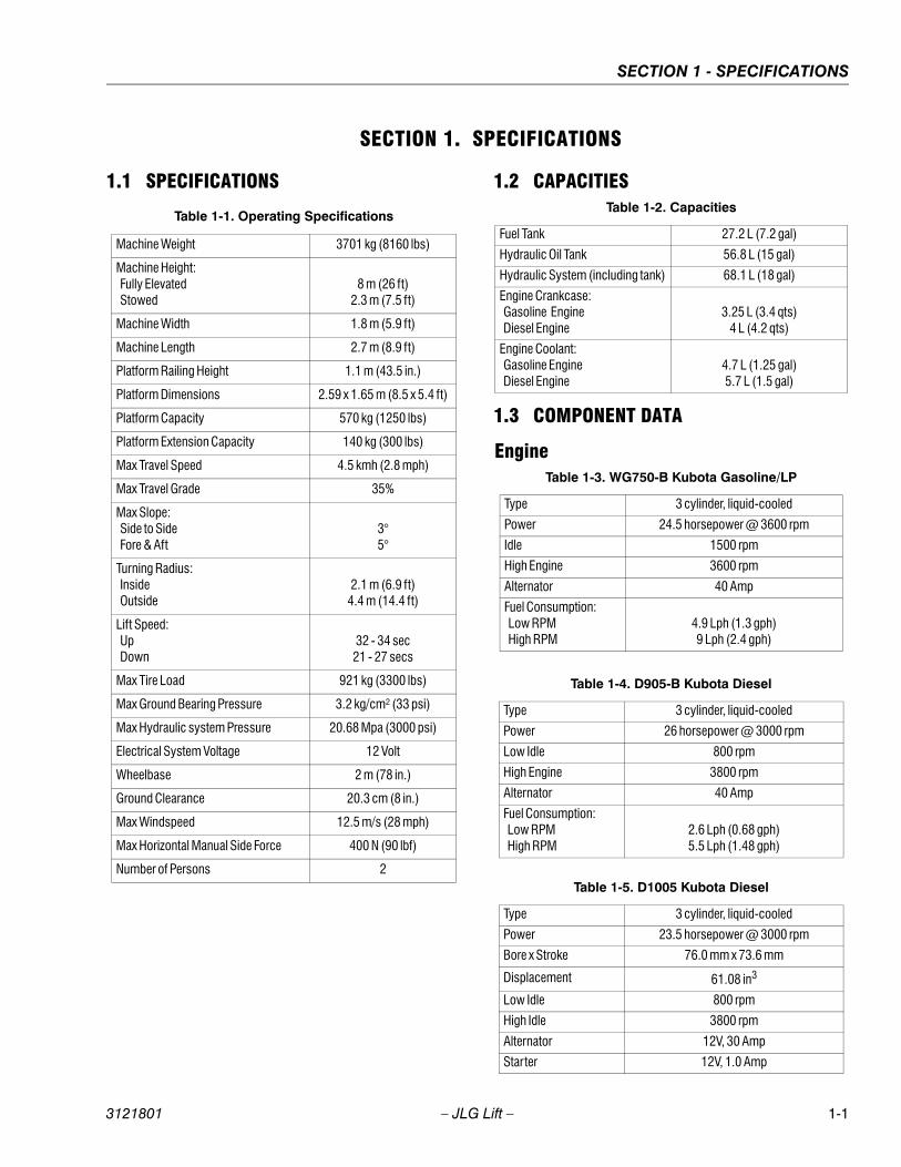
Table 1-1. Operating Specifications
Machine Weight 3701 kg (8160 lbs)
Machine Height: Fully Elevated Stowed
8 m (26 ft)2.3 m (7.5 ft)
Machine Width 1.8 m (5.9 ft)
Machine Length 2.7 m (8.9 ft)
Platform Railing Height 1.1 m (43.5 in.)
Platform Dimensions 2.59 x 1.65 m (8.5 x 5.4 ft)
Platform Capacity 570 kg (1250 lbs)
Platform Extension Capacity 140 kg (300 lbs)
Max Travel Speed 4.5 kmh (2.8 mph)
Max Travel Grade 35%
Max Slope: Side to Side Fore & Aft
3°5°
Turning Radius: Inside Outside
2.1 m (6.9 ft)4.4 m (14.4 ft)
Lift Speed: Up Down
32 - 34 sec21 - 27 secs
Max Tire Load 921 kg (3300 lbs)
Max Ground Bearing Pressure 3.2 kg/cm² (33 psi)
Max Hydraulic system Pressure 20.68 Mpa (3000 psi)
Electrical System Voltage 12 Volt
Wheelbase 2 m (78 in.)
Ground Clearance 20.3 cm (8 in.)
Max Windspeed 12.5 m/s (28 mph)
Max Horizontal Manual Side Force 400 N (90 lbf)
Number of Persons 2
Table 1-2. Capacities
Fuel Tank 27.2 L (7.2 gal)
Hydraulic Oil Tank 56.8 L (15 gal)
Hydraulic System (including tank) 68.1 L (18 gal)
Engine Crankcase: Gasoline Engine Diesel Engine
3.25 L (3.4 qts)4 L (4.2 qts)
Engine Coolant: Gasoline Engine Diesel Engine
4.7 L (1.25 gal)5.7 L (1.5 gal)
Table 1-3. WG750-B Kubota Gasoline/LP
Type 3 cylinder, liquid-cooled
Power 24.5 horsepower @ 3600 rpm
Idle 1500 rpm
High Engine 3600 rpm
Alternator 40 Amp
Fuel Consumption: Low RPM High RPM
4.9 Lph (1.3 gph)9 Lph (2.4 gph)
Table 1-4. D905-B Kubota Diesel
Type 3 cylinder, liquid-cooled
Power 26 horsepower @ 3000 rpm
Low Idle 800 rpm
High Engine 3800 rpm
Alternator 40 Amp
Fuel Consumption: Low RPM High RPM
2.6 Lph (0.68 gph)5.5 Lph (1.48 gph)
Table 1-5. D1005 Kubota Diesel
Type 3 cylinder, liquid-cooled
Power 23.5 horsepower @ 3000 rpm
Bore x Stroke 76.0 mm x 73.6 mm
Displacement 61.08 in3
Low Idle 800 rpm
High Idle 3800 rpm
Alternator 12V, 30 Amp
Starter 12V, 1.0 Amp
3121801 – JLG Lift – 1-1
SECTION 1 - SPECIFICATIONS
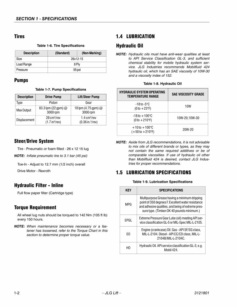
Tires
Pumps
Steer/Drive SystemTire - Pneumatic or foam filled - 26 x 12 15 lug
NOTE: Inflate pneumatic tire to 3.1 bar (45 psi)
Toe-In - Adjust to 12.7 mm (1/2 inch) overall
Drive Motor - Rexroth
Hydraulic Filter - InlineFull flow paper filter (Cartridge type)
Torque RequirementAll wheel lug nuts should be torqued to 142 Nm (105 ft lb)every 150 hours.
NOTE: When maintenance becomes necessary or a fas-tener has loosened, refer to the Torque Chart in thissection to determine proper torque value.
1.4 LUBRICATION
Hydraulic Oil
NOTE: Hydraulic oils must have anti-wear qualities at leastto API Service Classification GL-3, and sufficientchemical stability for mobile hydraulic system ser-vice. JLG Industries recommends Mobilfluid 424hydraulic oil, which has an SAE viscosity of 10W-30and a viscosity index of 152.
NOTE: Aside from JLG recommendations, it is not advisableto mix oils of different brands or types, as they maynot contain the same required additives or be ofcomparable viscosities. If use of hydraulic oil otherthan Mobilfluid 424 is desired, contact JLG Indus-tries for proper recommendations.
1.5 LUBRICATION SPECIFICATIONS
Table 1-6. Tire Specifications
Description (Standard) (Non-Marking)
Size 26x12-15
Load Range 8 Ply
Pressure 55 psi
Table 1-7. Pump Specifications
Description Drive Pump Lift/Steer Pump
Type Piston Gear
Max Output83.3 lpm (22 gpm) @
3000 rpm18 lpm (4.75 gpm) @
3000 rpm
Displacement28 cm³/rev (1.7 in³/rev)
1.4 cm³/rev (0.36 in.³/rev)
Table 1-8. Hydraulic Oil
HYDRAULIC SYSTEM OPERATING TEMPERATURE RANGE
SAE VISCOSITY GRADE
-18 to -5°C (0 to +23°F)
10W
-18 to +100°C (0 to +210°F)
10W-20,10W-30
+10 to +100°C (+50 to +210°F)
20W-20
Table 1-9. Lubrication Specifications
KEY SPECIFICATIONS
MPG
Multipurpose Grease having a minimum dripping point of 350 degrees F. Excellent water resistance and adhesive qualities, and being of extreme pres-
sure type. (Timken OK 40 pounds minimum.)
EPGLExtreme Pressure Gear Lube (oil) meeting API ser-vice classification GL-5 or MIL-Spec MIL-L-2105.
EOEngine (crankcase) Oil. Gas - API SF/SG class, MIL-L-2104. Diesel - API CC/CD class, MIL-L-
2104B/MIL-L-2104C.
HOHydraulic Oil. API service classification GL-3, e.g.
Mobil 424.
1-2 – JLG Lift – 3121801
SECTION 1 - SPECIFICATIONS
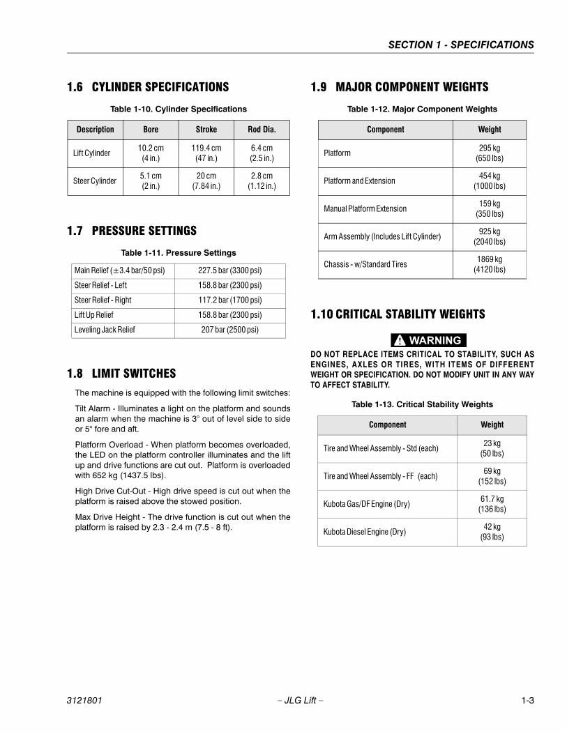
1.6 CYLINDER SPECIFICATIONS
1.7 PRESSURE SETTINGS
1.8 LIMIT SWITCHESThe machine is equipped with the following limit switches:
Tilt Alarm - Illuminates a light on the platform and soundsan alarm when the machine is 3° out of level side to sideor 5° fore and aft.
Platform Overload - When platform becomes overloaded,the LED on the platform controller illuminates and the liftup and drive functions are cut out. Platform is overloadedwith 652 kg (1437.5 lbs).
High Drive Cut-Out - High drive speed is cut out when theplatform is raised above the stowed position.
Max Drive Height - The drive function is cut out when theplatform is raised by 2.3 - 2.4 m (7.5 - 8 ft).
1.9 MAJOR COMPONENT WEIGHTS
1.10 CRITICAL STABILITY WEIGHTS
DO NOT REPLACE ITEMS CRITICAL TO STABILITY, SUCH AS
ENGINES, AXLES OR TIRES, WITH ITEMS OF DIFFERENTWEIGHT OR SPECIFICATION. DO NOT MODIFY UNIT IN ANY WAY
TO AFFECT STABILITY.
Table 1-10. Cylinder Specifications
Description Bore Stroke Rod Dia.
Lift Cylinder10.2 cm(4 in.)
119.4 cm(47 in.)
6.4 cm(2.5 in.)
Steer Cylinder5.1 cm(2 in.)
20 cm(7.84 in.)
2.8 cm(1.12 in.)
Table 1-11. Pressure Settings
Main Relief (±3.4 bar/50 psi) 227.5 bar (3300 psi)
Steer Relief - Left 158.8 bar (2300 psi)
Steer Relief - Right 117.2 bar (1700 psi)
Lift Up Relief 158.8 bar (2300 psi)
Leveling Jack Relief 207 bar (2500 psi)
Table 1-12. Major Component Weights
Component Weight
Platform295 kg
(650 lbs)
Platform and Extension454 kg
(1000 lbs)
Manual Platform Extension159 kg
(350 lbs)
Arm Assembly (Includes Lift Cylinder)925 kg
(2040 lbs)
Chassis - w/Standard Tires1869 kg
(4120 lbs)
Table 1-13. Critical Stability Weights
Component Weight
Tire and Wheel Assembly - Std (each)23 kg
(50 lbs)
Tire and Wheel Assembly - FF (each)69 kg
(152 lbs)
Kubota Gas/DF Engine (Dry)61.7 kg
(136 lbs)
Kubota Diesel Engine (Dry)42 kg
(93 lbs)
3121801 – JLG Lift – 1-3

SECTION 1 - SPECIFICATIONS
1.11 SERIAL NUMBER LOCATIONSFor machine identification, a serial number plate is affixedto the machine. The plate is located on the rear center ofthe machine frame, just below the middle step of the lad-der. In addition, if the serial number plate is damaged ormissing, the machine serial number is stamped on theright front frame rail, adjacent to the sizzor arms.
Figure 1-1. Serial Number Location
1-4 – JLG Lift – 3121801

SECTION 1 - SPECIFICATIONS
Figure 1-2. Lubrication Diagram
Table 1-14. Lubrication Chart
INDEX NO COMPONENT NUMBER/TYPE LUBE POINTS LUBE METHODINTERVAL
HOURS
1 Hydraulic Oil Reservoir Fill Cap/Drain PlugHO - Check HO Level
HO - Change HO10/500
2 Hydraulic Filter Element N/A Initial Change - 50 Hours 250
3
Engine Crankcase,Engine Oil Filter,
Engine Fuel Filter,Engine Fuel Filter (Kubota DF752)
Fill Cap/Drain Plug,Filter Element,Filter Element,Filter Element
Check Engine Oil Level,Initial Change - 50 Hours,
Check & Clean every 100 hrs,Check & Clean every 100 hrs
10/100,200,400,
Yearly
4 Rail Slides N/A MPG - Brush 100
KEY TO LUBRICANTS:
MPG - Multi-purpose Grease
EPGL - Extreme Pressure Gear Lube
HO - Hydraulic Oil (Mobil 424)
TO AVOID PERSONAL INJURY, USE SAFETY PROP FOR ALL
MAINTENANCE REQUIRING PLATFORM TO BE ELEVATED.
NOTE: Be sure to lubricate like items on each side
Recommended lubricating intervals are based onmachine operations under normal conditions. For
machines used in multi-shift operations and/orexposed to hostile environments or conditions,lubrication frequencies must be increased accord-ingly.
NOTE: Operate hydraulic functions through one completecycle before checking hydraulic oil level in tank. Oilshould be visible in ADD sight window on hydraulictank. If oil is not visible, add oil until oil is visible inboth ADD and FULL sight windows on tank. Do notoverfill tank.
Any time the pump coupling is removed, coatsplines of coupling with Texaco Code 1912 greaseprior to assembly.
3121801 – JLG Lift – 1-5
SECTION 1 - SPECIFICATIONS
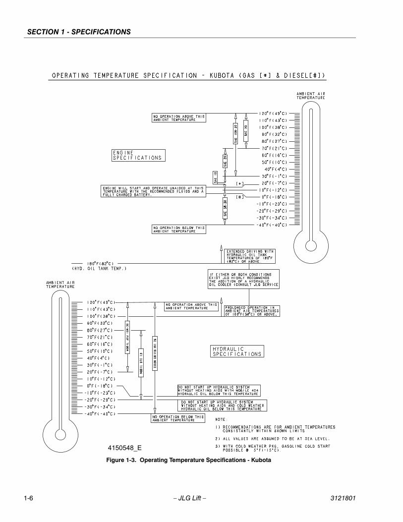
4150548_E
Figure 1-3. Operating Temperature Specifications - Kubota
1-6 – JLG Lift – 3121801

SECTION 1 - SPECIFICATIONS
1.12 TORQUE CHARTS
Figure 1-4. Torque Chart (SAE Fasteners - Sheet 1 of 7)
REFERENCE JLG ANEROBIC THREAD LOCKING COMPOUND
JLG P/N Loctite® P/N ND Industries P/N Description
0100011 242TM Vibra-TITETM 121 Medium Strength (Blue) 0100019 271TM Vibra-TITETM 140 High Strength (Red)0100071 262TM Vibra-TITETM 131 Medium - High Strength (Red)
Size TPI Bolt DiaTensile
Stress AreaClamp Load
In Sq In LB IN-LB [N.m] IN-LB [N.m] IN-LB [N.m] IN-LB [N.m]
4 40 0.1120 0.00604 380 8 0.9 6 0.748 0.1120 0.00661 420 9 1.0 7 0.8
6 32 0.1380 0.00909 580 16 1.8 12 1.440 0.1380 0.01015 610 18 2.0 13 1.5
8 32 0.1640 0.01400 900 30 3.4 22 2.536 0.1640 0.01474 940 31 3.5 23 2.6
10 24 0.1900 0.01750 1120 43 4.8 32 3.532 0.1900 0.02000 1285 49 5.5 36 4
1/4 20 0.2500 0.0318 2020 96 10.8 75 9 105 1228 0.2500 0.0364 2320 120 13.5 86 10 135 15
In Sq In LB FT-LB [N.m] FT-LB [N.m] FT-LB [N.m] FT-LB [N.m]
5/16 18 0.3125 0.0524 3340 17 23 13 18 19 26 16 2224 0.3125 0.0580 3700 19 26 14 19 21 29 17 23
3/8 16 0.3750 0.0775 4940 30 41 23 31 35 48 28 3824 0.3750 0.0878 5600 35 47 25 34 40 54 32 43
7/16 14 0.4375 0.1063 6800 50 68 35 47 55 75 45 6120 0.4375 0.1187 7550 55 75 40 54 60 82 50 68
1/2 13 0.5000 0.1419 9050 75 102 55 75 85 116 68 9220 0.5000 0.1599 10700 90 122 65 88 100 136 80 108
9/16 12 0.5625 0.1820 11600 110 149 80 108 120 163 98 13318 0.5625 0.2030 12950 120 163 90 122 135 184 109 148
5/8 11 0.6250 0.2260 14400 150 203 110 149 165 224 135 18318 0.6250 0.2560 16300 170 230 130 176 190 258 153 207
3/4 10 0.7500 0.3340 21300 260 353 200 271 285 388 240 32516 0.7500 0.3730 23800 300 407 220 298 330 449 268 363
7/8 9 0.8750 0.4620 29400 430 583 320 434 475 646 386 52314 0.8750 0.5090 32400 470 637 350 475 520 707 425 576
1 8 1.0000 0.6060 38600 640 868 480 651 675 918 579 78512 1.0000 0.6630 42200 700 949 530 719 735 1000 633 858
1 1/8 7 1.1250 0.7630 42300 800 1085 600 813 840 1142 714 96812 1.1250 0.8560 47500 880 1193 660 895 925 1258 802 1087
1 1/4 7 1.2500 0.9690 53800 1120 1518 840 1139 1175 1598 1009 136812 1.2500 1.0730 59600 1240 1681 920 1247 1300 1768 1118 1516
1 3/8 6 1.3750 1.1550 64100 1460 1979 1100 1491 1525 2074 1322 179212 1.3750 1.3150 73000 1680 2278 1260 1708 1750 2380 1506 2042
1 1/2 6 1.5000 1.4050 78000 1940 2630 1460 1979 2025 2754 1755 237912 1.5000 1.5800 87700 2200 2983 1640 2224 2300 3128 1974 2676
NO. 5000059 REV. J
Values for Zinc Yellow Chromate Fasteners (Ref 4150707)
SAE GRADE 5 BOLTS & GRADE 2 NUTS
Torque (Dry)
Torque
(Loctite® 262TM or Vibra-
TITETM 131)
Torque Lubricated
Torque
(Loctite® 242TM or 271TM
OR Vibra-TITETM 111 or 140)
3. * ASSEMBLY USES HARDENED WASHER
NOTES: 1. THESE TORQUE VALUES DO NOT APPLY TO CADMIUM PLATED FASTENERS2. ALL TORQUE VALUES ARE STATIC TORQUE MEASURED PER STANDARD AUDIT METHODS TOLERANCE = ±10%
3121801 – JLG Lift – 1-7
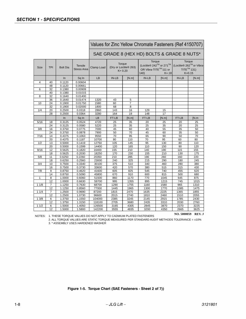
SECTION 1 - SPECIFICATIONS
Figure 1-5. Torque Chart (SAE Fasteners - Sheet 2 of 7))
Size TPI Bolt DiaTensile
Stress AreaClamp Load
In Sq In
4 40 0.1120 0.0060448 0.1120 0.00661
6 32 0.1380 0.0090940 0.1380 0.01015
8 32 0.1640 0.0140036 0.1640 0.01474
10 24 0.1900 0.0175032 0.1900 0.02000
1/4 20 0.2500 0.031828 0.2500 0.0364
In Sq In
5/16 18 0.3125 0.052424 0.3125 0.0580
3/8 16 0.3750 0.077524 0.3750 0.0878
7/16 14 0.4375 0.106320 0.4375 0.1187
1/2 13 0.5000 0.141920 0.5000 0.1599
9/16 12 0.5625 0.182018 0.5625 0.2030
5/8 11 0.6250 0.226018 0.6250 0.2560
3/4 10 0.7500 0.334016 0.7500 0.3730
7/8 9 0.8750 0.462014 0.8750 0.5090
1 8 1.0000 0.606012 1.0000 0.6630
1 1/8 7 1.1250 0.763012 1.1250 0.8560
1 1/4 7 1.2500 0.969012 1.2500 1.0730
1 3/8 6 1.3750 1.155012 1.3750 1.3150
1 1/2 6 1.5000 1.405012 1.5000 1.5800
NO. 5000059 REV. J
3. * ASSEMBLY USES HARDENED WASHER
NOTES: 1. THESE TORQUE VALUES DO NOT APPLY TO CADMIUM PLATED FASTENERS2. ALL TORQUE VALUES ARE STATIC TORQUE MEASURED PER STANDARD AUDIT METHODS TOLERANCE = ±10%
LB IN-LB [N.m] IN-LB [N.m] IN-LB [N.m]
1320 43 51580 60 71800 68 82860 143 16 129 153280 164 19 148 17
LB FT-LB [N.m] FT-LB [N.m] FT-LB [N.m
4720 25 35 20 25 20 255220 25 35 25 35 20 257000 45 60 40 55 35 507900 50 70 45 60 35 509550 70 95 65 90 50 70
10700 80 110 70 95 60 8012750 105 145 95 130 80 11014400 120 165 110 150 90 12016400 155 210 140 190 115 15518250 170 230 155 210 130 17520350 210 285 190 260 160 22023000 240 325 215 290 180 24530100 375 510 340 460 280 38033600 420 570 380 515 315 43041600 605 825 545 740 455 62045800 670 910 600 815 500 68051500 860 1170 770 1045 645 87559700 995 1355 895 1215 745 101568700 1290 1755 1160 1580 965 131077000 1445 1965 1300 1770 1085 147587200 1815 2470 1635 2225 1365 185596600 2015 2740 1810 2460 1510 2055104000 2385 3245 2145 2915 1785 2430118100 2705 3680 2435 3310 2030 2760126500 3165 4305 2845 3870 2370 3225142200 3555 4835 3200 4350 2665 3625
Torque
(Loctite® 242TM or 271TM
OR Vibra-TITETM 111 or 140) K=.18
Torque
(Loctite® 262TM or Vibra-
TITETM 131) K=0.15
SAE GRADE 8 (HEX HD) BOLTS & GRADE 8 NUTS*
Torque (Dry or Loctite® 263)
K= 0.20
1-8 – JLG Lift – 3121801
SECTION 1 - SPECIFICATIONS
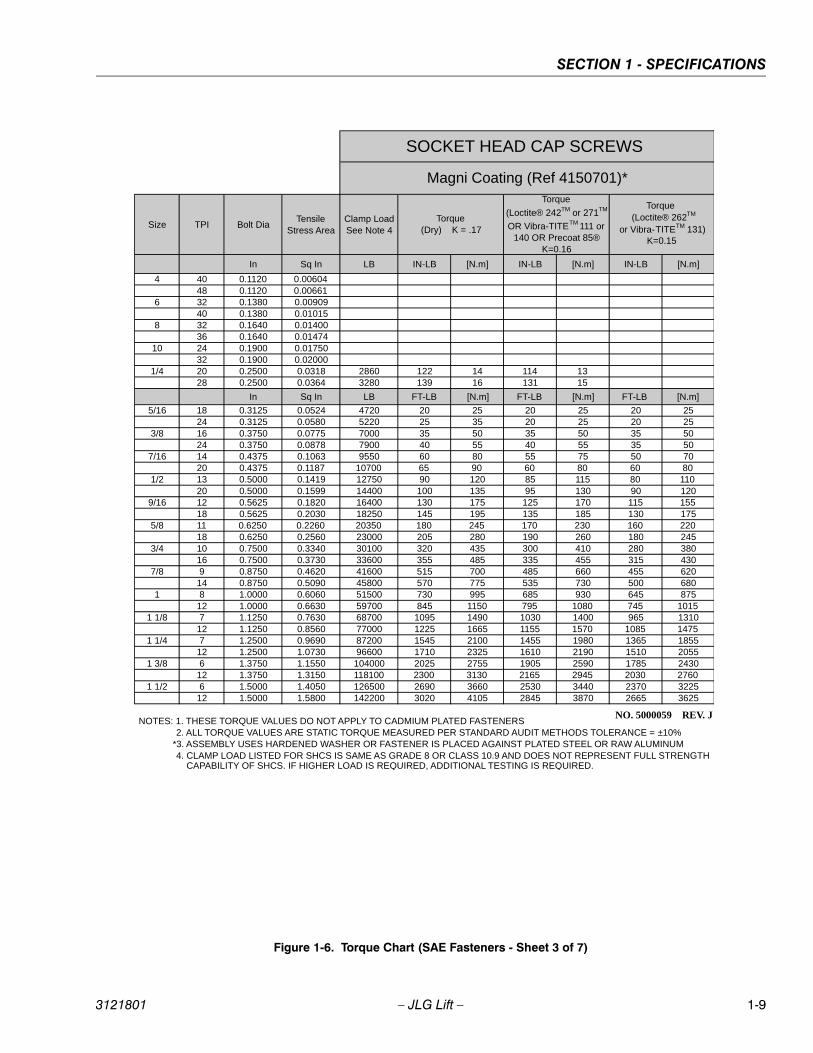
Figure 1-6. Torque Chart (SAE Fasteners - Sheet 3 of 7)
Size TPI Bolt DiaTensile
Stress AreaClamp Load See Note 4
In Sq In LB IN-LB [N.m] IN-LB [N.m] IN-LB [N.m]
4 40 0.1120 0.0060448 0.1120 0.00661
6 32 0.1380 0.0090940 0.1380 0.01015
8 32 0.1640 0.0140036 0.1640 0.01474
10 24 0.1900 0.0175032 0.1900 0.02000
1/4 20 0.2500 0.0318 2860 122 14 114 1328 0.2500 0.0364 3280 139 16 131 15
In Sq In LB FT-LB [N.m] FT-LB [N.m] FT-LB [N.m]
5/16 18 0.3125 0.0524 4720 20 25 20 25 20 2524 0.3125 0.0580 5220 25 35 20 25 20 25
3/8 16 0.3750 0.0775 7000 35 50 35 50 35 5024 0.3750 0.0878 7900 40 55 40 55 35 50
7/16 14 0.4375 0.1063 9550 60 80 55 75 50 7020 0.4375 0.1187 10700 65 90 60 80 60 80
1/2 13 0.5000 0.1419 12750 90 120 85 115 80 11020 0.5000 0.1599 14400 100 135 95 130 90 120
9/16 12 0.5625 0.1820 16400 130 175 125 170 115 15518 0.5625 0.2030 18250 145 195 135 185 130 175
5/8 11 0.6250 0.2260 20350 180 245 170 230 160 22018 0.6250 0.2560 23000 205 280 190 260 180 245
3/4 10 0.7500 0.3340 30100 320 435 300 410 280 38016 0.7500 0.3730 33600 355 485 335 455 315 430
7/8 9 0.8750 0.4620 41600 515 700 485 660 455 62014 0.8750 0.5090 45800 570 775 535 730 500 680
1 8 1.0000 0.6060 51500 730 995 685 930 645 87512 1.0000 0.6630 59700 845 1150 795 1080 745 1015
1 1/8 7 1.1250 0.7630 68700 1095 1490 1030 1400 965 131012 1.1250 0.8560 77000 1225 1665 1155 1570 1085 1475
1 1/4 7 1.2500 0.9690 87200 1545 2100 1455 1980 1365 185512 1.2500 1.0730 96600 1710 2325 1610 2190 1510 2055
1 3/8 6 1.3750 1.1550 104000 2025 2755 1905 2590 1785 243012 1.3750 1.3150 118100 2300 3130 2165 2945 2030 2760
1 1/2 6 1.5000 1.4050 126500 2690 3660 2530 3440 2370 322512 1.5000 1.5800 142200 3020 4105 2845 3870 2665 3625
NO. 5000059 REV. J
4. CLAMP LOAD LISTED FOR SHCS IS SAME AS GRADE 8 OR CLASS 10.9 AND DOES NOT REPRESENT FULL STRENGTH CAPABILITY OF SHCS. IF HIGHER LOAD IS REQUIRED, ADDITIONAL TESTING IS REQUIRED.
SOCKET HEAD CAP SCREWS
Magni Coating (Ref 4150701)*
Torque (Dry) K = .17
Torque
(Loctite® 242TM or 271TM
OR Vibra-TITETM 111 or 140 OR Precoat 85®
K=0.16
Torque (Loctite® 262TM
or Vibra-TITETM 131) K=0.15
2. ALL TORQUE VALUES ARE STATIC TORQUE MEASURED PER STANDARD AUDIT METHODS TOLERANCE = ±10% NOTES: 1. THESE TORQUE VALUES DO NOT APPLY TO CADMIUM PLATED FASTENERS
*3. ASSEMBLY USES HARDENED WASHER OR FASTENER IS PLACED AGAINST PLATED STEEL OR RAW ALUMINUM
3121801 – JLG Lift – 1-9

SECTION 1 - SPECIFICATIONS
Figure 1-7. Torque Chart (SAE Fasteners - Sheet 4 of 7)
Size TPI Bolt DiaTensile
Stress AreaClamp Load See Note 4
In Sq In LB IN-LB [N.m] IN-LB [N.m] IN-LB [N.m]
4 40 0.1120 0.0060448 0.1120 0.00661
6 32 0.1380 0.0090940 0.1380 0.01015
8 32 0.1640 0.0140036 0.1640 0.01474
10 24 0.1900 0.0175032 0.1900 0.02000
1/4 20 0.2500 0.0318 2860 143 16 129 1528 0.2500 0.0364 3280 164 19 148 17
In Sq In LB FT-LB [N.m] FT-LB [N.m] FT-LB [N.m]
5/16 18 0.3125 0.0524 4720 25 35 20 25 20 2524 0.3125 0.0580 5220 25 35 25 35 20 25
3/8 16 0.3750 0.0775 7000 45 60 40 55 35 5024 0.3750 0.0878 7900 50 70 45 60 35 50
7/16 14 0.4375 0.1063 9550 70 95 65 90 50 7020 0.4375 0.1187 10700 80 110 70 95 60 80
1/2 13 0.5000 0.1419 12750 105 145 95 130 80 11020 0.5000 0.1599 14400 120 165 110 150 90 120
9/16 12 0.5625 0.1820 16400 155 210 140 190 115 15518 0.5625 0.2030 18250 170 230 155 210 130 175
5/8 11 0.6250 0.2260 20350 210 285 190 260 160 22018 0.6250 0.2560 23000 240 325 215 290 180 245
3/4 10 0.7500 0.3340 30100 375 510 340 460 280 38016 0.7500 0.3730 33600 420 570 380 515 315 430
7/8 9 0.8750 0.4620 41600 605 825 545 740 455 62014 0.8750 0.5090 45800 670 910 600 815 500 680
1 8 1.0000 0.6060 51500 860 1170 775 1055 645 87512 1.0000 0.6630 59700 995 1355 895 1215 745 1015
1 1/8 7 1.1250 0.7630 68700 1290 1755 1160 1580 965 131012 1.1250 0.8560 77000 1445 1965 1300 1770 1085 1475
1 1/4 7 1.2500 0.9690 87200 1815 2470 1635 2225 1365 185512 1.2500 1.0730 96600 2015 2740 1810 2460 1510 2055
1 3/8 6 1.3750 1.1550 104000 2385 3245 2145 2915 1785 243012 1.3750 1.3150 118100 2705 3680 2435 3310 2030 2760
1 1/2 6 1.5000 1.4050 126500 3165 4305 2845 3870 2370 322512 1.5000 1.5800 142200 3555 4835 3200 4350 2665 3625
NO. 5000059 REV. J
4. CLAMP LOAD LISTED FOR SHCS IS SAME AS GRADE 8 OR CLASS 10.9 AND DOES NOT REPRESENT FULL STRENGTH CAPABILITY OF SHCS. IF HIGHER LOAD IS REQUIRED, ADDITIONAL TESTING IS REQUIRED.
SOCKET HEAD CAP SCREWS
Torque (Dry)
K = .20
Torque
(Loctite® 242TM or 271TM
OR Vibra-TITETM 111 or 140 OR Precoat 85®
K=0.18
Zinc Yellow Chromate Fasteners (Ref 4150707)*
2. ALL TORQUE VALUES ARE STATIC TORQUE MEASURED PER STANDARD AUDIT METHODS TOLERANCE = ±10% NOTES: 1. THESE TORQUE VALUES DO NOT APPLY TO CADMIUM PLATED FASTENERS
*3. ASSEMBLY USES HARDENED WASHER OR FASTENER IS PLACED AGAINST PLATED STEEL OR RAW ALUMINUM
Torque (Loctite® 262TM
or Vibra-TITETM 131) K=0.15
1-10 – JLG Lift – 3121801

SECTION 1 - SPECIFICATIONS
Figure 1-8. Torque Chart (METRIC Fasteners - Sheet 5 of 7))
Size PITCHTensile Stress Area
Clamp Load
Torque (Dry or Loctite®
263TM)
Torque (Lub)
Torque
(Loctite® 262TM
OR Vibra-
TITETM 131)
Torque (Loctite®
242TM or 271TM
OR Vibra-
TITETM 111 or 140)
Sq mm KN [N.m] [N.m] [N.m] [N.m]
3 0.5 5.03 2.19 1.3 1.0 1.2 1.4
3.5 0.6 6.78 2.95 2.1 1.6 1.9 2.3
4 0.7 8.78 3.82 3.1 2.3 2.8 3.4
5 0.8 14.20 6.18 6.2 4.6 5.6 6.8
6 1 20.10 8.74 11 7.9 9.4 12
7 1 28.90 12.6 18 13 16 19
8 1.25 36.60 15.9 26 19 23 28
10 1.5 58.00 25.2 50 38 45 55
12 1.75 84.30 36.7 88 66 79 97
14 2 115 50.0 140 105 126 154
16 2 157 68.3 219 164 197 241
18 2.5 192 83.5 301 226 271 331
20 2.5 245 106.5 426 320 383 469
22 2.5 303 132.0 581 436 523 639
24 3 353 153.5 737 553 663 811
27 3 459 199.5 1080 810 970 1130
30 3.5 561 244.0 1460 1100 1320 1530
33 3.5 694 302.0 1990 1490 1790 2090
36 4 817 355.5 2560 1920 2300 2690
42 4.5 1120 487.0 4090 3070 3680 4290
4. CLAMP LOAD LISTED FOR SHCS IS SAME AS GRADE 8 OR CLASS 10.9 AND DOES NOT REPRESENT FULL STRENGTH CAPABILITY OF SHCS. IF HIGHER LOAD IS REQUIRED, ADDITIONAL TESTING IS REQUIRED.
*3. ASSEMBLY USES HARDENED WASHER OR FASTENER IS PLACED AGAINST PLATED STEEL OR RAW ALUMINUM
CLASS 8.8 METRIC BOLTS CLASS 8 METRIC NUTS
NOTES: 1. THESE TORQUE VALUES DO NOT APPLY TO CADMIUM PLATED FASTENERS2. ALL TORQUE VALUES ARE STATIC TORQUE MEASURED PER STANDARD AUDIT METHODS TOLERANCE = ±10%
NO. 5000059 REV. J
3121801 – JLG Lift – 1-11

SECTION 1 - SPECIFICATIONS
Figure 1-9. Torque Chart (METRIC Fasteners - Sheet 6 of 7)
Size PITCHTensile Stress Area
Clamp Load
Torque (Dry or Loctite®
263TM) K = 0.20
Torque (Lub OR Loctite®
242TM or 271TM OR
Vibra-TITETM 111 or 140)
K= 0.18
Torque
(Loctite® 262TM OR
Vibra-TITETM 131) K=0.15
Sq mm KN [N.m] [N.m] [N.m]
3 0.5 5.03 3.13
3.5 0.6 6.78 4.22
4 0.7 8.78 5.47
5 0.8 14.20 8.85
6 1 20.10 12.5
7 1 28.90 18.0 25.2 22.7 18.9
8 1.25 36.60 22.8 36.5 32.8 27.4
10 1.5 58.00 36.1 70 65 55
12 1.75 84.30 52.5 125 115 95
14 2 115 71.6 200 180 150
16 2 157 97.8 315 280 235
18 2.5 192 119.5 430 385 325
20 2.5 245 152.5 610 550 460
22 2.5 303 189.0 830 750 625
24 3 353 222.0 1065 960 800
27 3 459 286.0 1545 1390 1160
30 3.5 561 349.5 2095 1885 1575
33 3.5 694 432.5 2855 2570 2140
36 4 817 509.0 3665 3300 2750
42 4.5 1120 698.0 5865 5275 4395
CLASS 10.9 METRIC BOLTS CLASS 10 METRIC NUTS
CLASS 12.9 SOCKET HEAD CAP SCREWS M3 - M5*
4. CLAMP LOAD LISTED FOR SHCS IS SAME AS GRADE 8 OR CLASS 10.9 AND DOES NOT REPRESENT FULL STRENGTH CAPABILITY OF SHCS. IF HIGHER LOAD IS REQUIRED, ADDITIONAL TESTING IS REQUIRED.
*3. ASSEMBLY USES HARDENED WASHER OR FASTENER IS PLACED AGAINST PLATED STEEL OR RAW ALUMINUM
NOTES: 1. THESE TORQUE VALUES DO NOT APPLY TO CADMIUM PLATED FASTENERS2. ALL TORQUE VALUES ARE STATIC TORQUE MEASURED PER STANDARD AUDIT METHODS TOLERANCE = ±10%
NO. 5000059 REV. J
1-12 – JLG Lift – 3121801
SECTION 1 - SPECIFICATIONS
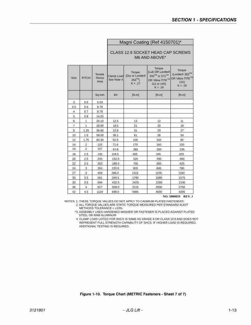
Figure 1-10. Torque Chart (METRIC Fasteners - Sheet 7 of 7)
Size PITCHTensile Stress Area
Clamp Load See Note 4
Torque (Dry or Loctite®
263TM) K = .17
Torque (Lub OR Loctite®
242TM or 271TM
OR Vibra-TITETM
111 or 140) K = .16
Torque
(Loctite® 262TM
OR Vibra-TITETM
131) K = .15
Sq mm kN [N.m] [N.m] [N.m]
3 0.5 5.03
3.5 0.6 6.78
4 0.7 8.78
5 0.8 14.20
6 1 20.10 12.5 13 12 11
7 1 28.90 18.0 21 20 19
8 1.25 36.60 22.8 31 29 27
10 1.5 58.00 36.1 61 58 54
12 1.75 84.30 52.5 105 100 95
14 2 115 71.6 170 160 150
16 2 157 97.8 265 250 235
18 2.5 192 119.5 365 345 325
20 2.5 245 152.5 520 490 460
22 2.5 303 189.0 705 665 625
24 3 353 220.0 900 845 790
27 3 459 286.0 1315 1235 1160
30 3.5 561 349.5 1780 1680 1575
33 3.5 694 432.5 2425 2285 2140
36 4 817 509.0 3115 2930 2750
42 4.5 1120 698.0 4985 4690 4395
CLASS 12.9 SOCKET HEAD CAP SCREWS M6 AND ABOVE*
4. CLAMP LOAD LISTED FOR SHCS IS SAME AS GRADE 8 OR CLASS 10.9 AND DOES NOT REPRESENT FULL STRENGTH CAPABILITY OF SHCS. IF HIGHER LOAD IS REQUIRED, ADDITIONAL TESTING IS REQUIRED.
*3. ASSEMBLY USES HARDENED WASHER OR FASTENER IS PLACED AGAINST PLATED STEEL OR RAW ALUMINUM
NOTES: 1. THESE TORQUE VALUES DO NOT APPLY TO CADMIUM PLATED FASTENERS2. ALL TORQUE VALUES ARE STATIC TORQUE MEASURED PER STANDARD AUDIT METHODS TOLERANCE = ±10%
NO. 5000059 REV. J
Magni Coating (Ref 4150701)*
3121801 – JLG Lift – 1-13
SECTION 1 - SPECIFICATIONS
NOTES:
1-14 – JLG Lift – 3121801
SECTION 2 - PROCEDURES
SECTION 2. PROCEDURES
2.1 GENERALThis section provides information necessary to performmaintenance on the scissor lift. Descriptions, techniquesand specific procedures are designed to provide the saf-est and most efficient maintenance for use by personnelresponsible for ensuring the correct installation and oper-ation of machine components and systems.
WHEN AN ABNORMAL CONDITION IS NOTED AND PROCEDURESCONTAINED HEREIN DO NOT SPECIFICALLY RELATE TO THE
NOTED IRREGULARITY, WORK SHOULD BE STOPPED ANDTECHNICALLY QUALIFIED GUIDANCE OBTAINED BEFORE WORKIS RESUMED.
The maintenance procedures included consist of servic-ing and component removal and installation, disassemblyand assembly, inspection, lubrication and cleaning. Infor-mation on any special tools or test equipment is also pro-vided where applicable.
2.2 SERVICING AND MAINTENANCE GUIDELINES
GeneralThe following information is provided to assist you in theuse and application of servicing and maintenance proce-dures contained in this chapter.
Safety and WorkmanshipYour safety, and that of others, is the first considerationwhen engaging in the maintenance of equipment. Alwaysbe conscious of weight. Never attempt to move heavyparts without the aid of a mechanical device. Do not allowheavy objects to rest in an unstable position. When raisinga portion of the equipment, ensure that adequate supportis provided.
Cleanliness1. The most important single item in preserving the
long service life of a machine is to keep dirt and for-eign materials out of the vital components. Precau-tions have been taken to safeguard against this.Shields, covers, seals, and filters are provided tokeep air, fuel, and oil supplies clean; however, theseitems must be maintained on a scheduled basis inorder to function properly.
2. At any time when air, fuel, or oil lines are discon-nected, clear adjacent areas as well as the openingsand fittings themselves. As soon as a line or compo-
nent is disconnected, cap or cover all openings toprevent entry of foreign matter.
3. Clean and inspect all parts during servicing or main-tenance, and assure that all passages and openingsare unobstructed. Cover all parts to keep themclean. Be sure all parts are clean before they areinstalled. New parts should remain in their contain-ers until they are ready to be used.
Components Removal and Installation
4. Use adjustable lifting devices, whenever possible, ifmechanical assistance is required. All slings (chains,cables, etc.) should be parallel to each other and asnear perpendicular as possible to top of part beinglifted.
5. Should it be necessary to remove a component onan angle, keep in mind that the capacity of an eye-bolt or similar bracket lessens, as the angle betweenthe supporting structure and the componentbecomes less than 90°.
6. If a part resists removal, check to see whether allnuts, bolts, cables, brackets, wiring, etc., have beenremoved and that no adjacent parts are interfering.
Component Disassembly and Reassembly
When disassembling or reassembling a component, com-plete the procedural steps in sequence. Do not partiallydisassemble or assemble one part, then start on another.Always recheck your work to assure that nothing has beenoverlooked. Do not make any adjustments, other thanthose recommended, without obtaining proper approval.
Pressure-Fit Parts
When assembling pressure-fit parts, use an “anti-seize” ormolybdenum disulfide base compound to lubricate themating surface.
Bearings
1. When a bearing is removed, cover it to keep out dirtand abrasives. Clean bearings in nonflammablecleaning solvent and allow to drip dry. Compressedair can be used but do not spin the bearing.
2. Discard bearings if the races and balls (or rollers)are pitted, scored, or burned.
3. If a bearing is found to be serviceable, apply a lightcoat of oil and wrap it in clean (waxed) paper. Do notunwrap reusable or new bearings until they areready to install.
3121801 – JLG Lift – 2-1

SECTION 2 - PROCEDURES
4. Lubricate new or used serviceable bearings beforeinstallation. When pressing a bearing into a retaineror bore, apply pressure to the outer race. If the bear-ing is to be installed on a shaft, apply pressure to theinner race.
GasketsCheck that holes in gaskets align with openings in themating parts. If it becomes necessary to hand-fabricate agasket, use gasket material or stock of equivalent materialand thickness. Be sure to cut holes in the right location, asblank gaskets can cause serious system damage.
Bolt Usage and Torque Application
1. Use bolts of proper length. A bolt which is too longwill bottom before the head is tight against its relatedpart. If a bolt is too short, there will not be enoughthread area to engage and hold the part properly.When replacing bolts, use only those having thesame specifications of the original, or one which isequivalent.
2. Unless specific torque requirements are given withinthe text, standard torque values should be used onheat-treated bolts, studs, and steel nuts, in accor-dance with recommended shop practices.
Hydraulic Lines and Electrical WiringClearly mark or tag hydraulic lines and electrical wiring, aswell as their receptacles, when disconnecting or removingthem from the unit. This will assure that they are correctlyreinstalled.
Hydraulic System
1. Keep the system clean. If evidence of metal or rub-ber particles is found in the hydraulic system, drainand flush the entire system.
2. Disassemble and reassemble parts on clean worksurface. Clean all metal parts with non-flammablecleaning solvent. Lubricate components, asrequired, to aid assembly.
LubricationService applicable components with the amount, type,and grade of lubricant recommended in this manual, atthe specified intervals. When recommended lubricants arenot available, consult your local supplier for an equivalentthat meets or exceeds the specifications listed.
BatteriesClean batteries, using a non-metallic brush and a solutionof baking soda and water. Rinse with clean water. Aftercleaning, thoroughly dry batteries and coat terminals withan anti-corrosion compound.
Lubrication and ServicingComponents and assemblies requiring lubrication andservicing are shown in Section 1.
2.3 LUBRICATION INFORMATION
Hydraulic System
1. The primary enemy of a hydraulic system is contam-ination. Contaminants enter the system by variousmeans, e.g., using inadequate hydraulic oil, allowingmoisture, grease, filings, sealing components, sand,etc., to enter when performing maintenance, or bypermitting the pump to cavitate due to insufficientsystem warm-up or leaks in the pump supply (suc-tion) lines.
2. The design and manufacturing tolerances of thecomponent working parts are very close, therefore,even the smallest amount of dirt or foreign matterentering a system can cause wear or damage to thecomponents and generally results in faulty opera-tion. Every precaution must be taken to keephydraulic oil clean, including reserve oil in storage.Hydraulic system filters should be checked,cleaned, and/or replaced as necessary, at the speci-fied intervals required in the Lubrication Chart inSection 1 and the Preventive Maintenance andInspection Chart in this section. Always examine fil-ters for evidence of metal particles.
3. Cloudy oils indicate a high moisture content whichpermits organic growth, resulting in oxidation or cor-rosion. If this condition occurs, the system must bedrained, flushed, and refilled with clean oil.
4. It is not advisable to mix oils of different brands ortypes, except as recommended, as they may notcontain the same required additives or be of compa-rable viscosities. Good grade mineral oils, with vis-cosities suited to the ambient temperatures in whichthe machine is operating, are recommended for use.
NOTE: Metal particles may appear in the oil or filters of newmachines due to the wear-in of meshing compo-nents.
Hydraulic Oil
1. Refer to Section1 for recommendations for viscosityranges.
2. JLG recommends Mobilfluid 424, which has an SAEviscosity of 10W-30 and a viscosity index of 152.
NOTE: Start-up of hydraulic system with oil temperaturesbelow -26°C (-15°F). is not recommended. If it isnecessary to start the system in a sub-zero environ-ment, it will be necessary to heat the oil with a low
2-2 – JLG Lift – 3121801

SECTION 2 - PROCEDURES
density, 100VAC heater to a minimum temperature of-26°C (-15°F).
3. The only exception to the above is to drain and fillthe system with Mobil DTE 11 oil or its equivalent.This will allow start up at temperatures down to-29°C(-20°F). However, use of this oil will give poor perfor-mance at temperatures above 49°C (120°F). Sys-tems using DTE 11 oil should not be operated attemperatures above 94°C (200°F). under any condi-tion.
Changing Hydraulic Oil1. Use of any of the recommended crankcase or
hydraulic oils eliminates the need for changing theoil on a regular basis. However, filter elements mustbe changed after the first 50 hours of operation andevery 300 hours thereafter. If it is necessary tochange the oil, use only those oils meeting orexceeding the specifications appearing in this man-ual. If unable to obtain the same type of oil suppliedwith the machine, consult local supplier for assis-tance in selecting the proper equivalent. Avoid mix-ing petroleum and synthetic base oils. JLGIndustries recommends changing the hydraulic oilevery two years.
2. Use every precaution to keep the hydraulic oil clean.If the oil must be poured from the original containerinto another, be sure to clean all possible contami-nants from the service container. Always clean themesh element of the filter and replace the cartridgeany time the system oil is changed.
3. While the unit is shut down, a good preventive main-tenance measure is to make a thorough inspectionof all hydraulic components, lines, fittings, etc., aswell as a functional check of each system, beforeplacing the machine back in service.
Lubrication SpecificationsSpecified lubricants, as recommended by the componentmanufacturers, are always the best choice, however,multi-purpose greases usually have the qualities whichmeet a variety of single purpose grease requirements.Should any question arise regarding the use of greases inmaintenance stock, consult your local supplier for evalua-tion.
2.4 CYLINDERS - THEORY OF OPERATION
Cylinders are of the double acting type. The Lift and Steersystems incorporate double acting cylinders. A doubleacting cylinder is one that requires oil flow to operate thecylinder rod in both directions. Directing oil (by actuatingthe corresponding control valve to the piston side of thecylinder) forces the piston to travel toward the rod end ofthe barrel, extending the cylinder rod (piston attached torod). When the oil flow is stopped, movement of the rodwill stop. By directing oil to the rod side of the cylinder, thepiston will be forced in the opposite direction and the cyl-inder rod will retract.
A holding valve is used in the Lift circuit to prevent retrac-tion of the cylinder rod should a hydraulic line rupture or aleak develop between the cylinder and its related controlvalve.
2.5 VALVES - THEORY OF OPERATION
Solenoid Control Valves (Bang-Bang)
Control valves used are four-way three-position solenoidvalves of the sliding spool design. When a circuit is acti-vated and the control valve solenoid energizes, the spoolis shifted and the corresponding work port opens to per-mit oil flow to the component in the selected circuit, withthe opposite work port opening to reservoir. Once the cir-cuit is deactivated (control returned to neutral), the valvespool returns to neutral (center) and oil flow is thendirected through the valve body and returns to reservoir. Atypical control valve consists of the valve body, slidingspool, and two solenoid assemblies. The spool ismachine fitted in the bore of the valve body. Lands on thespool divide the bore into various chambers, which, whenthe spool is shifted, align with corresponding ports in thevalve body open to common flow. At the same time otherports would be blocked to flow. The spool is spring-loaded to center position, therefore when the control isreleased, the spool automatically returns to neutral, pro-hibiting any flow through the circuit.
Proportional Control Valves
The proportional control valves provide a power outputmatching that required by the load. A small line connectedto a load sensing port feeds load pressure back to asequence valve. The sequence valve senses the differ-ence between the load and pump outlet pressure, andvaries the pump displacement to keep the difference con-stant. This differential pressure is applied across thevalve’s meter-in spool, with the effect that pump flow isdetermined by the degree of spool opening, independentof load pressure. Return lines are connected together,simplifying routing of return flow and to help reduce cavi-tation. Load sensing lines connect through shuttle valvesto feed the highest load signal back to the sequence
3121801 – JLG Lift – 2-3

SECTION 2 - PROCEDURES
valve. Integral actuator port relief valves, anti-cavitationcheck valves, and load check valves are standard.
Relief ValvesMain relief valves are installed at various points within thehydraulic system to protect associated systems and com-ponents against excessive pressure. Excessive pressurecan be developed when a cylinder reaches its limit oftravel and the flow of pressurized fluid continues from thesystem control. The relief valve provides an alternate pathfor the continuing flow from the pump, thus preventingrupture of the cylinder, hydraulic line or fitting. Completefailure of the system pump is also avoided by relieving cir-cuit pressure. The relief valve is installed in the circuitbetween the pump outlet (pressure line) and the cylinderof the circuit, generally as an integral part of the systemvalve bank. Relief pressures are set slightly higher thanthe load requirement, with the valve diverting excesspump delivery back to the reservoir when operating pres-sure of the component is reached.
Crossover Relief ValvesCrossover relief valves are used in circuits where the actu-ator requires an operating pressure lower than that sup-plied to the system. When the circuit is activated and therequired pressure at the actuator is developed, the cross-over relief diverts excess pump flow to the reservoir. Indi-vidual, integral reliefs are provided for each side of thecircuit.
2.6 COMPONENT FUNCTIONAL DESCRIPTION
Hydraulic PumpThe machine is equipped with two hydraulic pumps, afunction pump and a drive pump. The function pump is asingle-section gear pump that controls the lift and steerfunctions and provides a maximum output of 18 lpm (4.75gpm). The drive pump is a single-section piston pump thatcontrols the drive function and provides an output of 83.3lpm (22 gpm).
Lift Cylinder Counterbalance/Manual Descent Valve
The lift cylinder counterbalance/manual descent valve islocated on top of the lift cylinder. The counterbalancevalve is used to hold the platform in place when raised. Acable is connected to the valve which, when pulled, manu-ally opens the lift down port and allows the platform to belowered in the event hydraulic power is lost.
The lift cylinder counterbalance/manual descent valve islocated on top of the lift cylinder. The counterbalancevalve is used to hold the platform in place when raised. Acable is connected to the valve which, when pulled, manu-
ally opens the lift down port and allows the platform to belowered in the event hydraulic power is lost.
2.7 WEAR PADS
Sliding PadsThe original thickness of the sliding pads is 51 mm (2 in).Replace sliding pads when worn to 48 mm (1.875 in).
2.8 CYLINDER CHECKING PROCEDURES
NOTE: Cylinder checks must be performed any time a cylin-der component is replaced or when improper systemoperation is suspected.
Cylinder w/o Counterbalance Valves - Steer Cylinder
OPERATE FUNCTIONS FROM GROUND CONTROL STATIONONLY.
DO NOT FULLY EXTEND CYLINDER TO END OF STROKE.RETRACT CYLINDER SLIGHTLY TO AVOID TRAPPING PRES-SURE.
1. Using all applicable safety precautions, activatemotor and fully extend cylinder to be checked. Shutdown motor.
2. Carefully disconnect hydraulic hose from retract portof cylinder. There will be initial weeping of hydraulicfluid which can be caught in a suitable container.After the initial discharge, there should be no furtherleakage from the retract port.
3. Activate motor and activate cylinder extend function.Check retract port for leakage.
4. If cylinder leakage is 6-8 drops per minute or more,piston seals are defective and must be replaced. Ifcylinder retract port leakage is less than 6-8 dropsper minute, carefully reconnect hose to retract portand retract cylinder.
5. With cylinder fully retracted, shut down motor andcarefully disconnect hydraulic hose from cylinderextend port.
6. Activate motor and activate cylinder retract function.Check extend port for leakage.
7. If cylinder leakage is 6-8 drops per minute or more,piston seals are defective and must be replaced. Ifextend port leakage is less than 6-8 drops per min-ute, carefully reconnect hose to extend port, thenactivate cylinder through one complete cycle andcheck for leaks.
2-4 – JLG Lift – 3121801
SECTION 2 - PROCEDURES
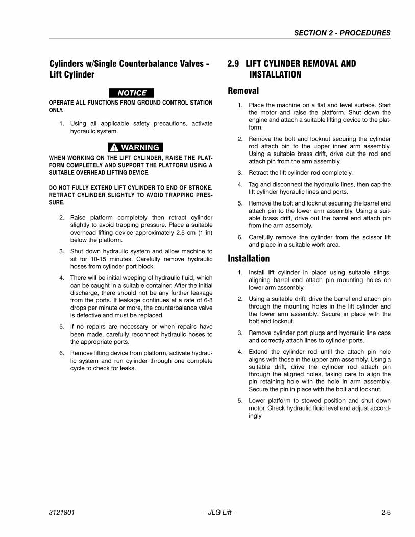
Cylinders w/Single Counterbalance Valves - Lift Cylinder
OPERATE ALL FUNCTIONS FROM GROUND CONTROL STATIONONLY.
1. Using all applicable safety precautions, activatehydraulic system.
WHEN WORKING ON THE LIFT CYLINDER, RAISE THE PLAT-FORM COMPLETELY AND SUPPORT THE PLATFORM USING A
SUITABLE OVERHEAD LIFTING DEVICE.
DO NOT FULLY EXTEND LIFT CYLINDER TO END OF STROKE.
RETRACT CYLINDER SLIGHTLY TO AVOID TRAPPING PRES-SURE.
2. Raise platform completely then retract cylinderslightly to avoid trapping pressure. Place a suitableoverhead lifting device approximately 2.5 cm (1 in)below the platform.
3. Shut down hydraulic system and allow machine tosit for 10-15 minutes. Carefully remove hydraulichoses from cylinder port block.
4. There will be initial weeping of hydraulic fluid, whichcan be caught in a suitable container. After the initialdischarge, there should not be any further leakagefrom the ports. If leakage continues at a rate of 6-8drops per minute or more, the counterbalance valveis defective and must be replaced.
5. If no repairs are necessary or when repairs havebeen made, carefully reconnect hydraulic hoses tothe appropriate ports.
6. Remove lifting device from platform, activate hydrau-lic system and run cylinder through one completecycle to check for leaks.
2.9 LIFT CYLINDER REMOVAL AND INSTALLATION
Removal1. Place the machine on a flat and level surface. Start
the motor and raise the platform. Shut down theengine and attach a suitable lifting device to the plat-form.
2. Remove the bolt and locknut securing the cylinderrod attach pin to the upper inner arm assembly.Using a suitable brass drift, drive out the rod endattach pin from the arm assembly.
3. Retract the lift cylinder rod completely.
4. Tag and disconnect the hydraulic lines, then cap thelift cylinder hydraulic lines and ports.
5. Remove the bolt and locknut securing the barrel endattach pin to the lower arm assembly. Using a suit-able brass drift, drive out the barrel end attach pinfrom the arm assembly.
6. Carefully remove the cylinder from the scissor liftand place in a suitable work area.
Installation1. Install lift cylinder in place using suitable slings,
aligning barrel end attach pin mounting holes onlower arm assembly.
2. Using a suitable drift, drive the barrel end attach pinthrough the mounting holes in the lift cylinder andthe lower arm assembly. Secure in place with thebolt and locknut.
3. Remove cylinder port plugs and hydraulic line capsand correctly attach lines to cylinder ports.
4. Extend the cylinder rod until the attach pin holealigns with those in the upper arm assembly. Using asuitable drift, drive the cylinder rod attach pinthrough the aligned holes, taking care to align thepin retaining hole with the hole in arm assembly.Secure the pin in place with the bolt and locknut.
5. Lower platform to stowed position and shut downmotor. Check hydraulic fluid level and adjust accord-ingly
3121801 – JLG Lift – 2-5
SECTION 2 - PROCEDURES
.
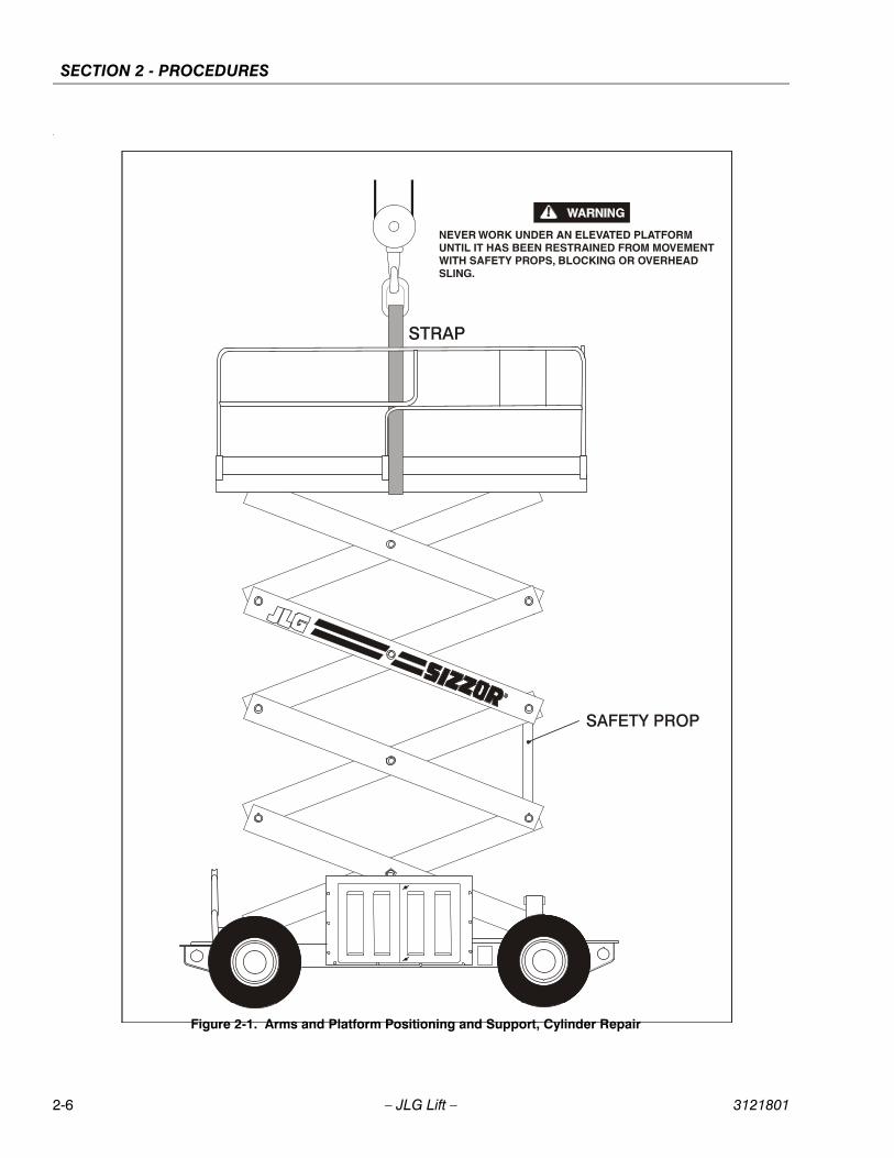
Figure 2-1. Arms and Platform Positioning and Support, Cylinder Repair
2-6 – JLG Lift – 3121801

SECTION 2 - PROCEDURES
1
2
3
4
5
6
78
9
10
1112
1314
1516 17
18
19
20
20
1. Barrel
2. Rod
3. Solenoid Valve
4. Cotter Pin
5. Cable Adaptor
6. Restrictor/Check Valve
7. Locknut
8. Wear Ring
9. Seal
10. Piston
11. O-Ring
12. Spacer
13. O-Ring
14. Back-Up Ring
15. Wear Ring
16. Seal
17. O-Ring
18. Head
19. Wiper
20. Bushing
Figure 2-2. Lift Cylinder
3121801 – JLG Lift – 2-7
SECTION 2 - PROCEDURES
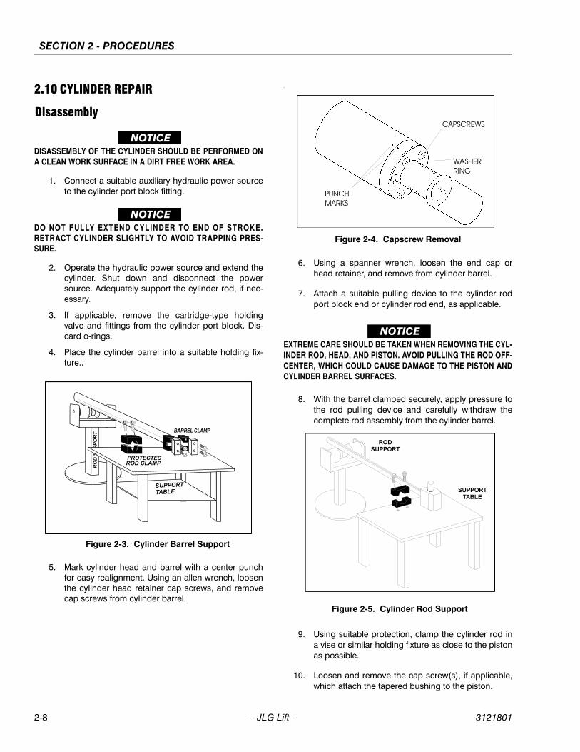
2.10 CYLINDER REPAIR
Disassembly
DISASSEMBLY OF THE CYLINDER SHOULD BE PERFORMED ON
A CLEAN WORK SURFACE IN A DIRT FREE WORK AREA.
1. Connect a suitable auxiliary hydraulic power sourceto the cylinder port block fitting.
DO NOT FULLY EXTEND CYLINDER TO END OF STROKE.
RETRACT CYLINDER SLIGHTLY TO AVOID TRAPPING PRES-SURE.
2. Operate the hydraulic power source and extend thecylinder. Shut down and disconnect the powersource. Adequately support the cylinder rod, if nec-essary.
3. If applicable, remove the cartridge-type holdingvalve and fittings from the cylinder port block. Dis-card o-rings.
4. Place the cylinder barrel into a suitable holding fix-ture..
5. Mark cylinder head and barrel with a center punchfor easy realignment. Using an allen wrench, loosenthe cylinder head retainer cap screws, and removecap screws from cylinder barrel.
.
6. Using a spanner wrench, loosen the end cap orhead retainer, and remove from cylinder barrel.
7. Attach a suitable pulling device to the cylinder rodport block end or cylinder rod end, as applicable.
EXTREME CARE SHOULD BE TAKEN WHEN REMOVING THE CYL-
INDER ROD, HEAD, AND PISTON. AVOID PULLING THE ROD OFF-
CENTER, WHICH COULD CAUSE DAMAGE TO THE PISTON AND
CYLINDER BARREL SURFACES.
8. With the barrel clamped securely, apply pressure tothe rod pulling device and carefully withdraw thecomplete rod assembly from the cylinder barrel.
9. Using suitable protection, clamp the cylinder rod ina vise or similar holding fixture as close to the pistonas possible.
10. Loosen and remove the cap screw(s), if applicable,which attach the tapered bushing to the piston.
Figure 2-3. Cylinder Barrel Support
Figure 2-4. Capscrew Removal
Figure 2-5. Cylinder Rod Support
2-8 – JLG Lift – 3121801
SECTION 2 - PROCEDURES
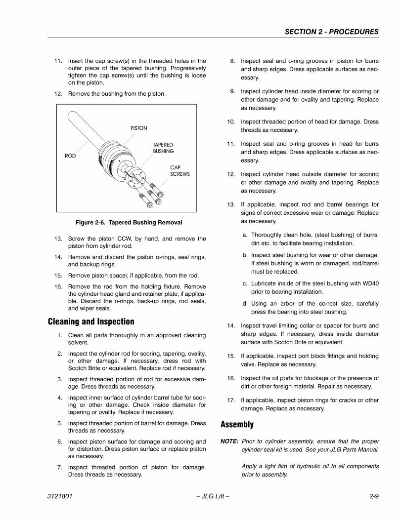
11. Insert the cap screw(s) in the threaded holes in theouter piece of the tapered bushing. Progressivelytighten the cap screw(s) until the bushing is looseon the piston.
12. Remove the bushing from the piston.
13. Screw the piston CCW, by hand, and remove thepiston from cylinder rod.
14. Remove and discard the piston o-rings, seal rings,and backup rings.
15. Remove piston spacer, if applicable, from the rod.
16. Remove the rod from the holding fixture. Removethe cylinder head gland and retainer plate, if applica-ble. Discard the o-rings, back-up rings, rod seals,and wiper seals.
Cleaning and Inspection1. Clean all parts thoroughly in an approved cleaning
solvent.
2. Inspect the cylinder rod for scoring, tapering, ovality,or other damage. If necessary, dress rod withScotch Brite or equivalent. Replace rod if necessary.
3. Inspect threaded portion of rod for excessive dam-age. Dress threads as necessary.
4. Inspect inner surface of cylinder barrel tube for scor-ing or other damage. Check inside diameter fortapering or ovality. Replace if necessary.
5. Inspect threaded portion of barrel for damage. Dressthreads as necessary.
6. Inspect piston surface for damage and scoring andfor distortion. Dress piston surface or replace pistonas necessary.
7. Inspect threaded portion of piston for damage.Dress threads as necessary.
8. Inspect seal and o-ring grooves in piston for burrsand sharp edges. Dress applicable surfaces as nec-essary.
9. Inspect cylinder head inside diameter for scoring orother damage and for ovality and tapering. Replaceas necessary.
10. Inspect threaded portion of head for damage. Dressthreads as necessary.
11. Inspect seal and o-ring grooves in head for burrsand sharp edges. Dress applicable surfaces as nec-essary.
12. Inspect cylinder head outside diameter for scoringor other damage and ovality and tapering. Replaceas necessary.
13. If applicable, inspect rod and barrel bearings forsigns of correct excessive wear or damage. Replaceas necessary.
a. Thoroughly clean hole, (steel bushing) of burrs,dirt etc. to facilitate bearing installation.
b. Inspect steel bushing for wear or other damage.If steel bushing is worn or damaged, rod/barrelmust be replaced.
c. Lubricate inside of the steel bushing with WD40prior to bearing installation.
d. Using an arbor of the correct size, carefullypress the bearing into steel bushing.
14. Inspect travel limiting collar or spacer for burrs andsharp edges. If necessary, dress inside diametersurface with Scotch Brite or equivalent.
15. If applicable, inspect port block fittings and holdingvalve. Replace as necessary.
16. Inspect the oil ports for blockage or the presence ofdirt or other foreign material. Repair as necessary.
17. If applicable, inspect piston rings for cracks or otherdamage. Replace as necessary.
Assembly
NOTE: Prior to cylinder assembly, ensure that the propercylinder seal kit is used. See your JLG Parts Manual.
Apply a light film of hydraulic oil to all componentsprior to assembly.
Figure 2-6. Tapered Bushing Removal
3121801 – JLG Lift – 2-9
SECTION 2 - PROCEDURES
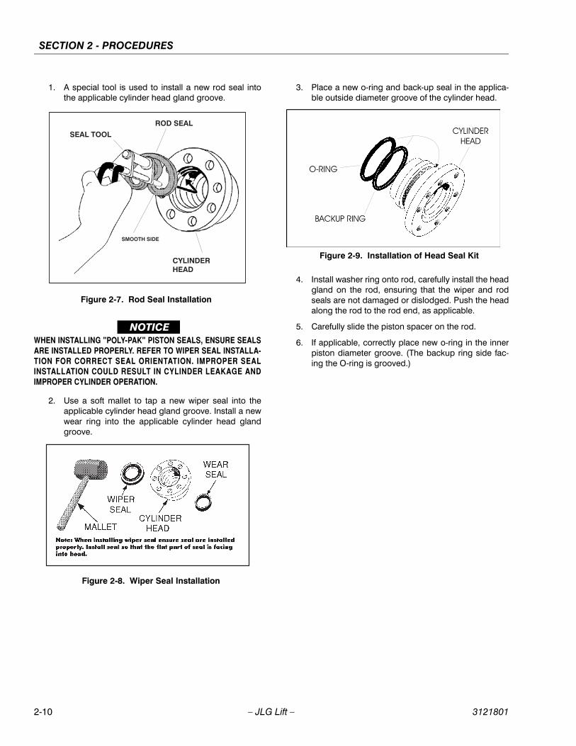
1. A special tool is used to install a new rod seal intothe applicable cylinder head gland groove.
WHEN INSTALLING "POLY-PAK" PISTON SEALS, ENSURE SEALS
ARE INSTALLED PROPERLY. REFER TO WIPER SEAL INSTALLA-TION FOR CORRECT SEAL ORIENTATION. IMPROPER SEALINSTALLATION COULD RESULT IN CYLINDER LEAKAGE AND
IMPROPER CYLINDER OPERATION.
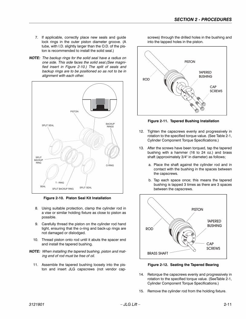
2. Use a soft mallet to tap a new wiper seal into theapplicable cylinder head gland groove. Install a newwear ring into the applicable cylinder head glandgroove.
3. Place a new o-ring and back-up seal in the applica-ble outside diameter groove of the cylinder head.
4. Install washer ring onto rod, carefully install the headgland on the rod, ensuring that the wiper and rodseals are not damaged or dislodged. Push the headalong the rod to the rod end, as applicable.
5. Carefully slide the piston spacer on the rod.
6. If applicable, correctly place new o-ring in the innerpiston diameter groove. (The backup ring side fac-ing the O-ring is grooved.)
Figure 2-7. Rod Seal Installation
Figure 2-8. Wiper Seal Installation
Figure 2-9. Installation of Head Seal Kit
2-10 – JLG Lift – 3121801
SECTION 2 - PROCEDURES
7. If applicable, correctly place new seals and guidelock rings in the outer piston diameter groove. (Atube, with I.D. slightly larger than the O.D. of the pis-ton is recommended to install the solid seal.)
NOTE: The backup rings for the solid seal have a radius onone side. This side faces the solid seal.(See magni-fied insert in Figure 2-10.) The split of seals andbackup rings are to be positioned so as not to be inalignment with each other.
8. Using suitable protection, clamp the cylinder rod ina vise or similar holding fixture as close to piston aspossible.
9. Carefully thread the piston on the cylinder rod handtight, ensuring that the o-ring and back-up rings arenot damaged or dislodged.
10. Thread piston onto rod until it abuts the spacer endand install the tapered bushing.
NOTE: When installing the tapered bushing, piston and mat-ing end of rod must be free of oil.
11. Assemble the tapered bushing loosely into the pis-ton and insert JLG capscrews (not vendor cap-
screws) through the drilled holes in the bushing andinto the tapped holes in the piston.
12. Tighten the capscrews evenly and progressively inrotation to the specified torque value. (See Table 2-1,Cylinder Component Torque Specifications.)
13. After the screws have been torqued, tap the taperedbushing with a hammer (16 to 24 oz.) and brassshaft (approximately 3/4" in diameter) as follows;
a. Place the shaft against the cylinder rod and incontact with the bushing in the spaces betweenthe capscrews.
b. Tap each space once; this means the taperedbushing is tapped 3 times as there are 3 spacesbetween the capscrews.
14. Retorque the capscrews evenly and progressively inrotation to the specified torque value. (SeeTable 2-1,Cylinder Component Torque Specifications.)
15. Remove the cylinder rod from the holding fixture.
Figure 2-10. Piston Seal Kit Installation
Figure 2-11. Tapered Bushing Installation
Figure 2-12. Seating the Tapered Bearing
3121801 – JLG Lift – 2-11

SECTION 2 - PROCEDURES
16. Place new guide locks and seals in the applicableoutside diameter grooves of the cylinder piston.(See Figure 2-10., Piston Seal Kit Installation )
17. Position the cylinder barrel in a suitable holding fix-ture.
EXTREME CARE SHOULD BE TAKEN WHEN INSTALLING THE
CYLINDER ROD, HEAD, AND PISTON. AVOID PULLING THE RODOFF-CENTER, WHICH COULD CAUSE DAMAGE TO THE PISTONAND CYLINDER BARREL SURFACES.
18. With barrel clamped securely, and while adequatelysupporting the rod, insert the piston end into thebarrel cylinder. Ensure that the piston loading o-ringand seal ring are not damaged or dislodged.
19. Continue pushing the rod into the barrel until the cyl-inder head gland can be inserted into the barrel cyl-inder.
20. Secure the cylinder head gland using the washerring and socket head bolts.
21. After the cylinder has been reassembled, the rodshould be pushed all the way in (fully retracted) priorto the reinstallation of any holding valve or valves.
22. If applicable, install the cartridge-type holding valveand fittings in the rod port block, using new o-ringsas applicable. (See Table 2-1, Cylinder ComponentTorque Specifications).
IF THE CYLINDER IS TO BE TESTED PRIOR TO INSTALLATION ON
THE MACHINE, EXTREME CARE SHOULD BE USED TO INSURETHAT THE OUTER END OF THE ROD IS SUPPORTED. USEEITHER A TRAVELING OVERHEAD HOIST, FORK-LIFT, OR OTHER
MEANS TO SUPPORT THE OVERHANGING WEIGHT OF THEEXTENDING ROD.
23. If applicable, install the cartridge-type holding valveand fittings in the port block using new o-rings asapplicable. (SeeTable 2-2, Holding Valve TorqueSpecifications).
Figure 2-13. Poly-Pak Piston Seal Installation
Figure 2-14. Rod Assembly Installation
Table 2-1. Cylinder Component Torque Specifications
ComponentTorque Value (w/Loctite)
Tapered Bushing Retaining Screws - Lift Cylinder80 ft lbs
(108 Nm)
Head Retaining Screws - Lift Cylinder9 ft lbs
(12 Nm)
Table 2-2. Holding Valve Torque Specifications
Description Torque Value
Sun - 7/8 hex M20 x 1.5 thds30 - 35 ft lbs(41 - 48 Nm)
Sun - 1-1/8 hex 1 - 14 UNS thds45 - 50 ft lbs(61 - 68 Nm)
Sun - 1-1/4 hex M36 x 2 thds150 - 153 ft lbs(204 - 207 Nm)
Racine - 1-1/8 hex 1-1/16 - 12 thds50 - 55 ft lbs(68 - 75 Nm)
Racine - 1-3/8 hex 1-3/16 - 12 thds75 - 80 ft lbs
(102 - 109 Nm)
Racine - 1-7/8 hex 1-5/8 - 12 thds100 - 110 ft lbs(136 - 149 Nm)
2-12 – JLG Lift – 3121801
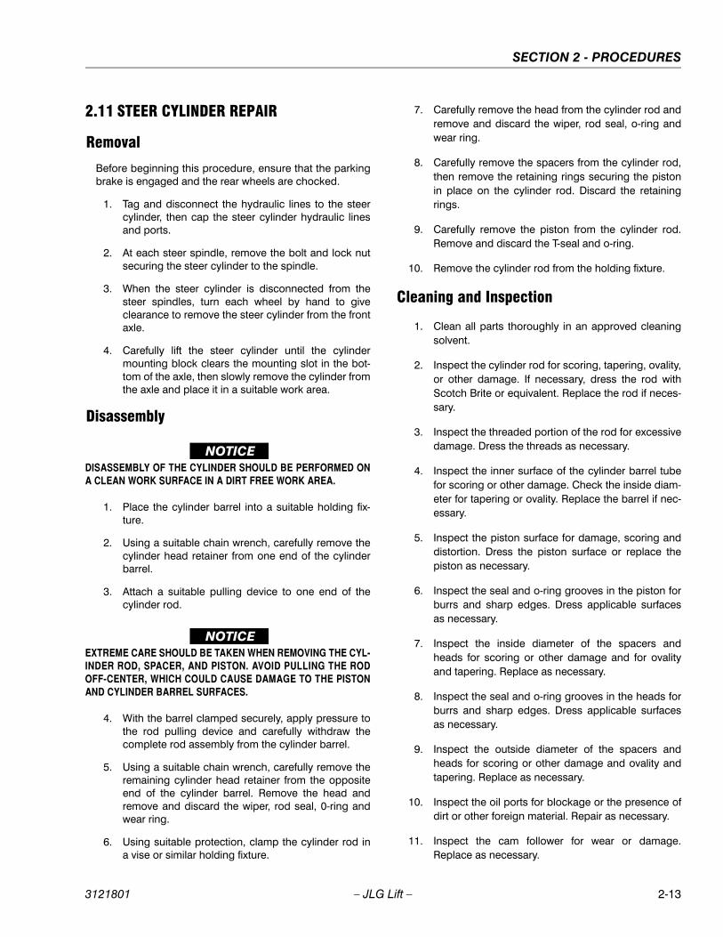
SECTION 2 - PROCEDURES
2.11 STEER CYLINDER REPAIR
Removal
Before beginning this procedure, ensure that the parkingbrake is engaged and the rear wheels are chocked.
1. Tag and disconnect the hydraulic lines to the steercylinder, then cap the steer cylinder hydraulic linesand ports.
2. At each steer spindle, remove the bolt and lock nutsecuring the steer cylinder to the spindle.
3. When the steer cylinder is disconnected from thesteer spindles, turn each wheel by hand to giveclearance to remove the steer cylinder from the frontaxle.
4. Carefully lift the steer cylinder until the cylindermounting block clears the mounting slot in the bot-tom of the axle, then slowly remove the cylinder fromthe axle and place it in a suitable work area.
Disassembly
DISASSEMBLY OF THE CYLINDER SHOULD BE PERFORMED ON
A CLEAN WORK SURFACE IN A DIRT FREE WORK AREA.
1. Place the cylinder barrel into a suitable holding fix-ture.
2. Using a suitable chain wrench, carefully remove thecylinder head retainer from one end of the cylinderbarrel.
3. Attach a suitable pulling device to one end of thecylinder rod.
EXTREME CARE SHOULD BE TAKEN WHEN REMOVING THE CYL-INDER ROD, SPACER, AND PISTON. AVOID PULLING THE RODOFF-CENTER, WHICH COULD CAUSE DAMAGE TO THE PISTON
AND CYLINDER BARREL SURFACES.
4. With the barrel clamped securely, apply pressure tothe rod pulling device and carefully withdraw thecomplete rod assembly from the cylinder barrel.
5. Using a suitable chain wrench, carefully remove theremaining cylinder head retainer from the oppositeend of the cylinder barrel. Remove the head andremove and discard the wiper, rod seal, 0-ring andwear ring.
6. Using suitable protection, clamp the cylinder rod ina vise or similar holding fixture.
7. Carefully remove the head from the cylinder rod andremove and discard the wiper, rod seal, o-ring andwear ring.
8. Carefully remove the spacers from the cylinder rod,then remove the retaining rings securing the pistonin place on the cylinder rod. Discard the retainingrings.
9. Carefully remove the piston from the cylinder rod.Remove and discard the T-seal and o-ring.
10. Remove the cylinder rod from the holding fixture.
Cleaning and Inspection
1. Clean all parts thoroughly in an approved cleaningsolvent.
2. Inspect the cylinder rod for scoring, tapering, ovality,or other damage. If necessary, dress the rod withScotch Brite or equivalent. Replace the rod if neces-sary.
3. Inspect the threaded portion of the rod for excessivedamage. Dress the threads as necessary.
4. Inspect the inner surface of the cylinder barrel tubefor scoring or other damage. Check the inside diam-eter for tapering or ovality. Replace the barrel if nec-essary.
5. Inspect the piston surface for damage, scoring anddistortion. Dress the piston surface or replace thepiston as necessary.
6. Inspect the seal and o-ring grooves in the piston forburrs and sharp edges. Dress applicable surfacesas necessary.
7. Inspect the inside diameter of the spacers andheads for scoring or other damage and for ovalityand tapering. Replace as necessary.
8. Inspect the seal and o-ring grooves in the heads forburrs and sharp edges. Dress applicable surfacesas necessary.
9. Inspect the outside diameter of the spacers andheads for scoring or other damage and ovality andtapering. Replace as necessary.
10. Inspect the oil ports for blockage or the presence ofdirt or other foreign material. Repair as necessary.
11. Inspect the cam follower for wear or damage.Replace as necessary.
3121801 – JLG Lift – 2-13
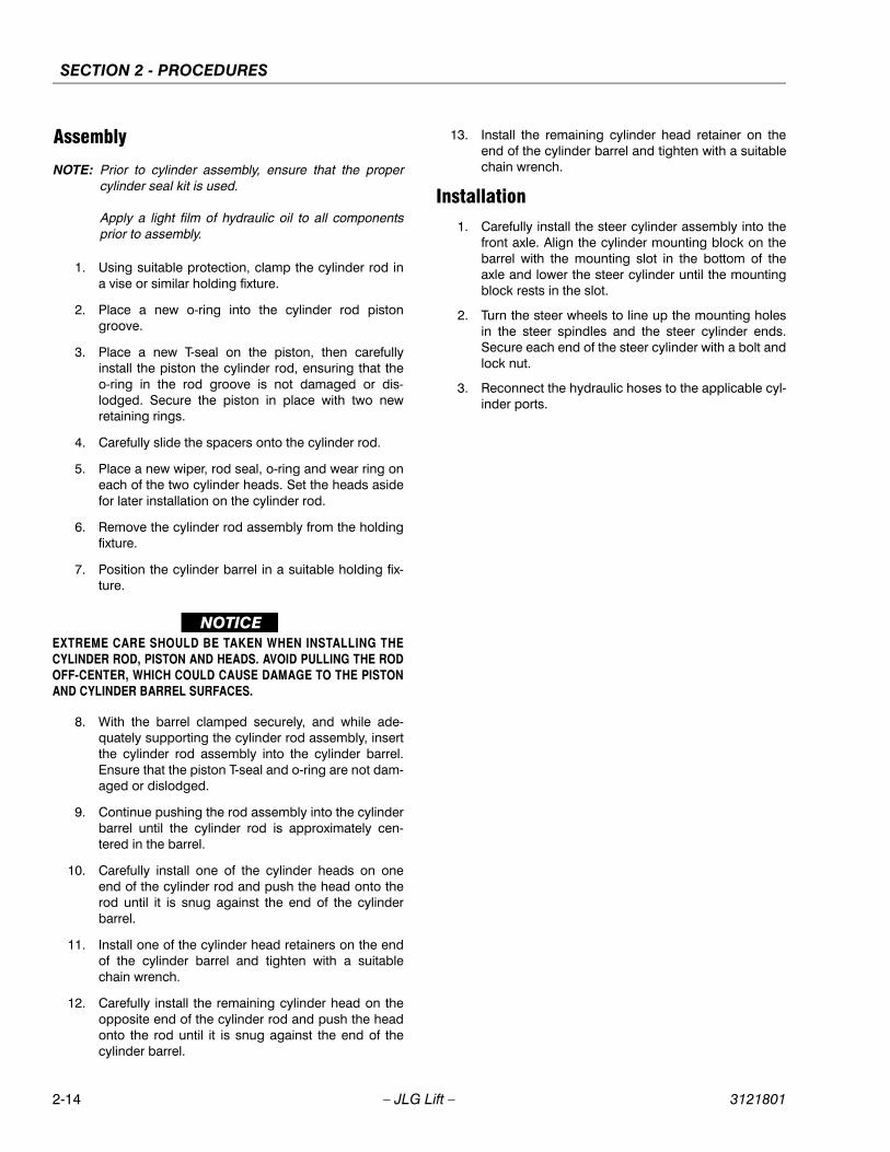
SECTION 2 - PROCEDURES
Assembly
NOTE: Prior to cylinder assembly, ensure that the propercylinder seal kit is used.
Apply a light film of hydraulic oil to all componentsprior to assembly.
1. Using suitable protection, clamp the cylinder rod ina vise or similar holding fixture.
2. Place a new o-ring into the cylinder rod pistongroove.
3. Place a new T-seal on the piston, then carefullyinstall the piston the cylinder rod, ensuring that theo-ring in the rod groove is not damaged or dis-lodged. Secure the piston in place with two newretaining rings.
4. Carefully slide the spacers onto the cylinder rod.
5. Place a new wiper, rod seal, o-ring and wear ring oneach of the two cylinder heads. Set the heads asidefor later installation on the cylinder rod.
6. Remove the cylinder rod assembly from the holdingfixture.
7. Position the cylinder barrel in a suitable holding fix-ture.
EXTREME CARE SHOULD BE TAKEN WHEN INSTALLING THE
CYLINDER ROD, PISTON AND HEADS. AVOID PULLING THE RODOFF-CENTER, WHICH COULD CAUSE DAMAGE TO THE PISTONAND CYLINDER BARREL SURFACES.
8. With the barrel clamped securely, and while ade-quately supporting the cylinder rod assembly, insertthe cylinder rod assembly into the cylinder barrel.Ensure that the piston T-seal and o-ring are not dam-aged or dislodged.
9. Continue pushing the rod assembly into the cylinderbarrel until the cylinder rod is approximately cen-tered in the barrel.
10. Carefully install one of the cylinder heads on oneend of the cylinder rod and push the head onto therod until it is snug against the end of the cylinderbarrel.
11. Install one of the cylinder head retainers on the endof the cylinder barrel and tighten with a suitablechain wrench.
12. Carefully install the remaining cylinder head on theopposite end of the cylinder rod and push the headonto the rod until it is snug against the end of thecylinder barrel.
13. Install the remaining cylinder head retainer on theend of the cylinder barrel and tighten with a suitablechain wrench.
Installation1. Carefully install the steer cylinder assembly into the
front axle. Align the cylinder mounting block on thebarrel with the mounting slot in the bottom of theaxle and lower the steer cylinder until the mountingblock rests in the slot.
2. Turn the steer wheels to line up the mounting holesin the steer spindles and the steer cylinder ends.Secure each end of the steer cylinder with a bolt andlock nut.
3. Reconnect the hydraulic hoses to the applicable cyl-inder ports.
2-14 – JLG Lift – 3121801
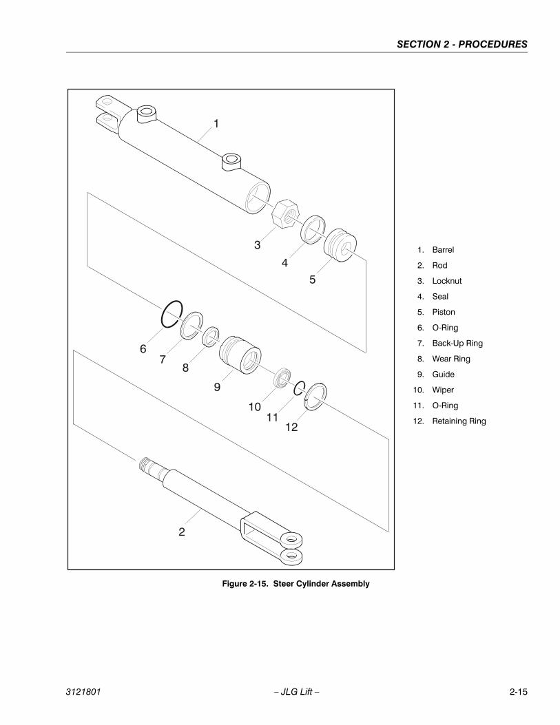
SECTION 2 - PROCEDURES
1
54
3
67
8
9
1011
12
2
Figure 2-15. Steer Cylinder Assembly
1. Barrel
2. Rod
3. Locknut
4. Seal
5. Piston
6. O-Ring
7. Back-Up Ring
8. Wear Ring
9. Guide
10. Wiper
11. O-Ring
12. Retaining Ring
3121801 – JLG Lift – 2-15

SECTION 2 - PROCEDURES
1. Barrel
2. Counter Balance Valve
3. Check Valve
4. Plug
5. Nut
6. Locking Screw
7. Flatwasher, 1 1/4" Narrow
8. Guidelock
9. Polyseal
10. Piston
11. O-Ring
12. Spacer Tube
13. O-Ring
14. Wear Ring
15. Head
16. Hydrolock
17. Wiper Seal
18. Cap
19. Rod
20. Plate
21. Trailer Ball
22. Jack Pad
23. Retainer Ring
24. Bolt
Figure 2-16. Leveling Jack Assembly - (Prior to S/N 105371)
2-16 – JLG Lift – 3121801
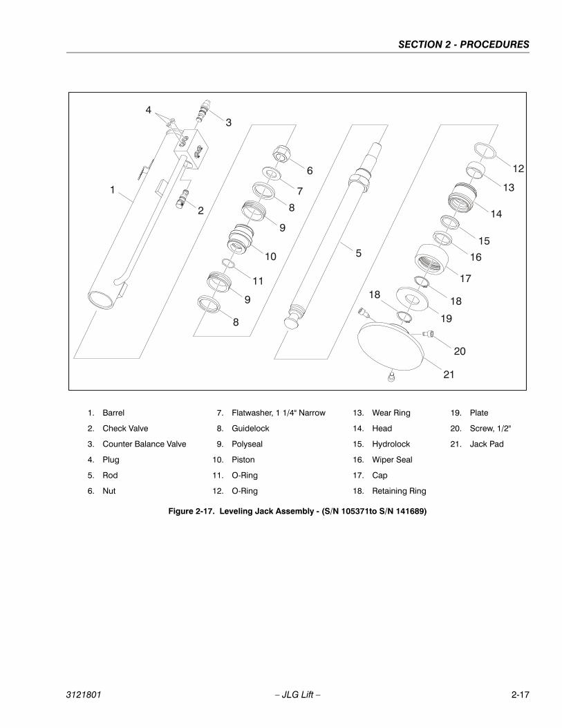
SECTION 2 - PROCEDURES
1
2
34
5
6
7
8
9
10
11
9
8
12
13
14
15
16
17
18
19
18
20
21
1. Barrel
2. Check Valve
3. Counter Balance Valve
4. Plug
5. Rod
6. Nut
7. Flatwasher, 1 1/4" Narrow
8. Guidelock
9. Polyseal
10. Piston
11. O-Ring
12. O-Ring
13. Wear Ring
14. Head
15. Hydrolock
16. Wiper Seal
17. Cap
18. Retaining Ring
19. Plate
20. Screw, 1/2"
21. Jack Pad
Figure 2-17. Leveling Jack Assembly - (S/N 105371to S/N 141689)
3121801 – JLG Lift – 2-17
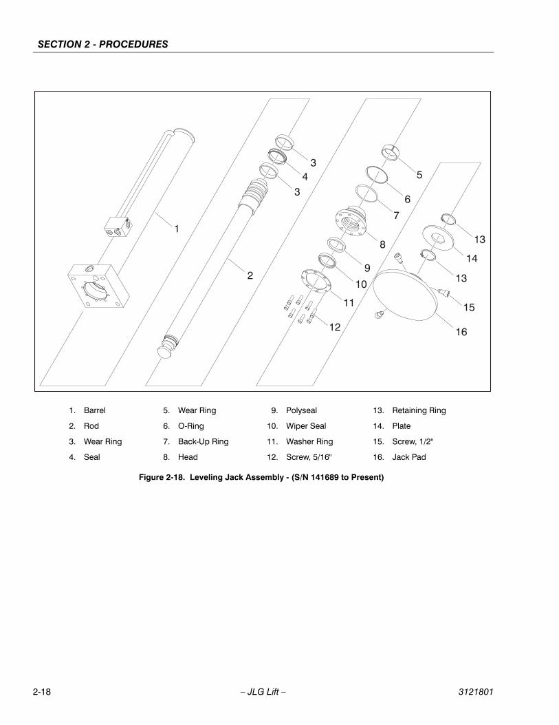
SECTION 2 - PROCEDURES
1
2
34
3
12
11
10
9
8
7
6
5
13
14
13
15
16
1. Barrel
2. Rod
3. Wear Ring
4. Seal
5. Wear Ring
6. O-Ring
7. Back-Up Ring
8. Head
9. Polyseal
10. Wiper Seal
11. Washer Ring
12. Screw, 5/16"
13. Retaining Ring
14. Plate
15. Screw, 1/2"
16. Jack Pad
Figure 2-18. Leveling Jack Assembly - (S/N 141689 to Present)
2-18 – JLG Lift – 3121801
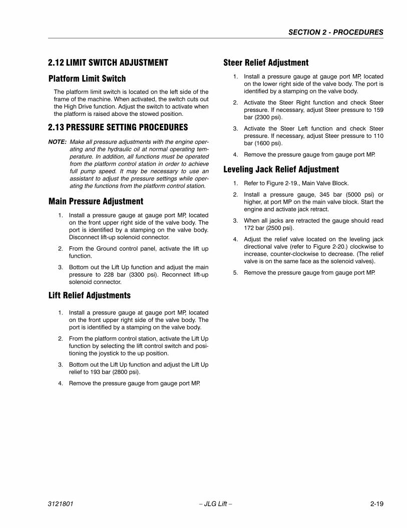
SECTION 2 - PROCEDURES
2.12 LIMIT SWITCH ADJUSTMENT
Platform Limit SwitchThe platform limit switch is located on the left side of theframe of the machine. When activated, the switch cuts outthe High Drive function. Adjust the switch to activate whenthe platform is raised above the stowed position.
2.13 PRESSURE SETTING PROCEDURES
NOTE: Make all pressure adjustments with the engine oper-ating and the hydraulic oil at normal operating tem-perature. In addition, all functions must be operatedfrom the platform control station in order to achievefull pump speed. It may be necessary to use anassistant to adjust the pressure settings while oper-ating the functions from the platform control station.
Main Pressure Adjustment1. Install a pressure gauge at gauge port MP, located
on the front upper right side of the valve body. Theport is identified by a stamping on the valve body.Disconnect lift-up solenoid connector.
2. From the Ground control panel, activate the lift upfunction.
3. Bottom out the Lift Up function and adjust the mainpressure to 228 bar (3300 psi). Reconnect lift-upsolenoid connector.
Lift Relief Adjustments
1. Install a pressure gauge at gauge port MP, locatedon the front upper right side of the valve body. Theport is identified by a stamping on the valve body.
2. From the platform control station, activate the Lift Upfunction by selecting the lift control switch and posi-tioning the joystick to the up position.
3. Bottom out the Lift Up function and adjust the Lift Uprelief to 193 bar (2800 psi).
4. Remove the pressure gauge from gauge port MP.
Steer Relief Adjustment1. Install a pressure gauge at gauge port MP, located
on the lower right side of the valve body. The port isidentified by a stamping on the valve body.
2. Activate the Steer Right function and check Steerpressure. If necessary, adjust Steer pressure to 159bar (2300 psi).
3. Activate the Steer Left function and check Steerpressure. If necessary, adjust Steer pressure to 110bar (1600 psi).
4. Remove the pressure gauge from gauge port MP.
Leveling Jack Relief Adjustment1. Refer to Figure 2-19., Main Valve Block.
2. Install a pressure gauge, 345 bar (5000 psi) orhigher, at port MP on the main valve block. Start theengine and activate jack retract.
3. When all jacks are retracted the gauge should read172 bar (2500 psi).
4. Adjust the relief valve located on the leveling jackdirectional valve (refer to Figure 2-20.) clockwise toincrease, counter-clockwise to decrease. (The reliefvalve is on the same face as the solenoid valves).
5. Remove the pressure gauge from gauge port MP.
3121801 – JLG Lift – 2-19
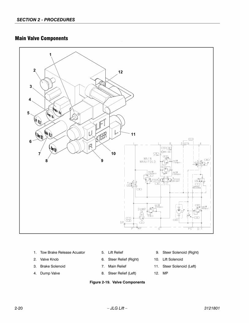
SECTION 2 - PROCEDURES
Main Valve Components.
1
2
3
4
5
6
78 9
10
11
12
1. Tow Brake Release Acuator
2. Valve Knob
3. Brake Solenoid
4. Dump Valve
5. Lift Relief
6. Steer Relief (Right)
7. Main Relief
8. Steer Relief (Left)
9. Steer Solenoid (Right)
10. Lift Solenoid
11. Steer Solenoid (Left)
12. MP
Figure 2-19. Valve Components
2-20 – JLG Lift – 3121801

SECTION 2 - PROCEDURES
Leveling Jacks Directional Valve
Figure 2-20. Leveling Jacks Directional Valve
PA1
PA3
PA4
PA2
PB
1P
B2
PB
4P
B3
LP T
PA1
PA3
PA4
PA2 PB1
PB2
PB4
PB3
LP
T
Leveling Jacks - PressureRelief Valve Location
Table 2-3. Leveling Jacks Directional Valve Torque Specs
Item Torque
PA4 54 Nm (40 lb-ft)
PB4 31 Nm (23 lb-ft)
T 54 Nm (40 lb-ft)
3121801 – JLG Lift – 2-21

SECTION 2 - PROCEDURES
2.14 DRIVE PUMP START-UP PROCEDURE
THE FOLLOWING PROCEDURE SHOULD ALWAYS BE PER-FORMED WHEN STARTING A NEW PUMP OR WHEN RESTARTING
AN INSTALLATION IN WHICH EITHER THE PUMP OR MOTORHAVE BEEN REMOVED FROM THE SYSTEM.
THE FOLLOWING PROCEDURE SHOULD ALWAYS BE PER-FORMED WHEN STARTING A NEW PUMP OR WHEN RESTARTING
AN INSTALLATION IN WHICH EITHER THE PUMP OR MOTORHAVE BEEN REMOVED FROM THE SYSTEM.
THE FOLLOWING PROCEDURE MAY REQUIRE THE MACHINE TOBE DISABLED (WHEELS RAISED OFF THE GROUND, DRIVEFUNCTION DISCONNECTED, ETC.) WHILE PERFORMING THE
PROCEDURE IN ORDER TO PREVENT INJURY TO TECHNICIANAND OTHER PERSONNEL. TAKE NECESSARY SAFETY PRECAU-TIONS BEFORE MOVING THE MACHINE.
Prior to installing pump and/or motor, inspect unit(s) fordamage incurred during shipping and handling. Makecertain all system components (reservoir, hoses, valves,fittings, heat exchanger, etc.) are clean prior to filling withhydraulic fluid.
Fill reservoir with recommended hydraulic fluid, whichshould be passed through a 10 micron (nominal, nobypass) filter prior to entering the reservoir. The use ofcontaminated fluid will cause damage to components,which may result in unexpected machine movement.
The inlet line leading from the reservoir to the pumpshould be filled prior to start-up. Check inlet line for prop-erly tightened fittings and make sure it is free of restric-tions and air leaks.
Be certain to fill pump and/or motor housing with cleanhydraulic fluid prior to start-up. Fill housing by pouring fil-tered oil into upper case drain port.
Install a 0 to 35 bar (0 to 500 psi) pressure gauge in thecharge pressure gauge port to monitor charge pressureduring start-up.
It is recommended that the external control input signalelectrical connections be disconnected at the pump con-trol until after initial start-up. This will allow the pump toremain in its neutral position.
“Jog” or slowly rotate prime mover until charge pressurestarts to rise. Start prime mover and run at the lowest pos-sible RPM until charge pressure has been established.Excess air may be bled from high pressure lines throughhigh pressure gauge ports.
DO NOT START PRIME MOVER UNLESS PUMP IS IN NEUTRAL
POSITION (0 DEGREES SWASHPLATE ANGLE). TAKE PRECAU-TIONS TO PREVENT MACHINE MOVEMENT IN CASE PUMP ISACTUATED DURING INITIAL START-UP.
Once charge pressure has been established, increasespeed to normal operating RPM. Charge pressure shouldbe approximately 20.7 bar (300 psi) minimum. If chargepressure is incorrect, shut down and determine cause forimproper pressure.
INADEQUATE CHARGE PRESSURE WILL AFFECT THE OPERA-
TOR’S ABILITY TO CONTROL THE MACHINE.
Shut down prime mover and connect external controlinput signal. start prime mover, checking to be certainpump remains in neutral. with prime mover at normaloperating speed, slowly check for forward and reversemachine operation.
Charge pressure should remain at 20.7 bar to 22.1 bar(300 psi to 320 psi) minimum during forward or reverseoperation. Continue to cycle slowly between forward andreverse for at least five minutes.
Shut down prime mover, remove gauges, and plug ports.Check reservoir level and add fluid if necessary
2-22 – JLG Lift – 3121801
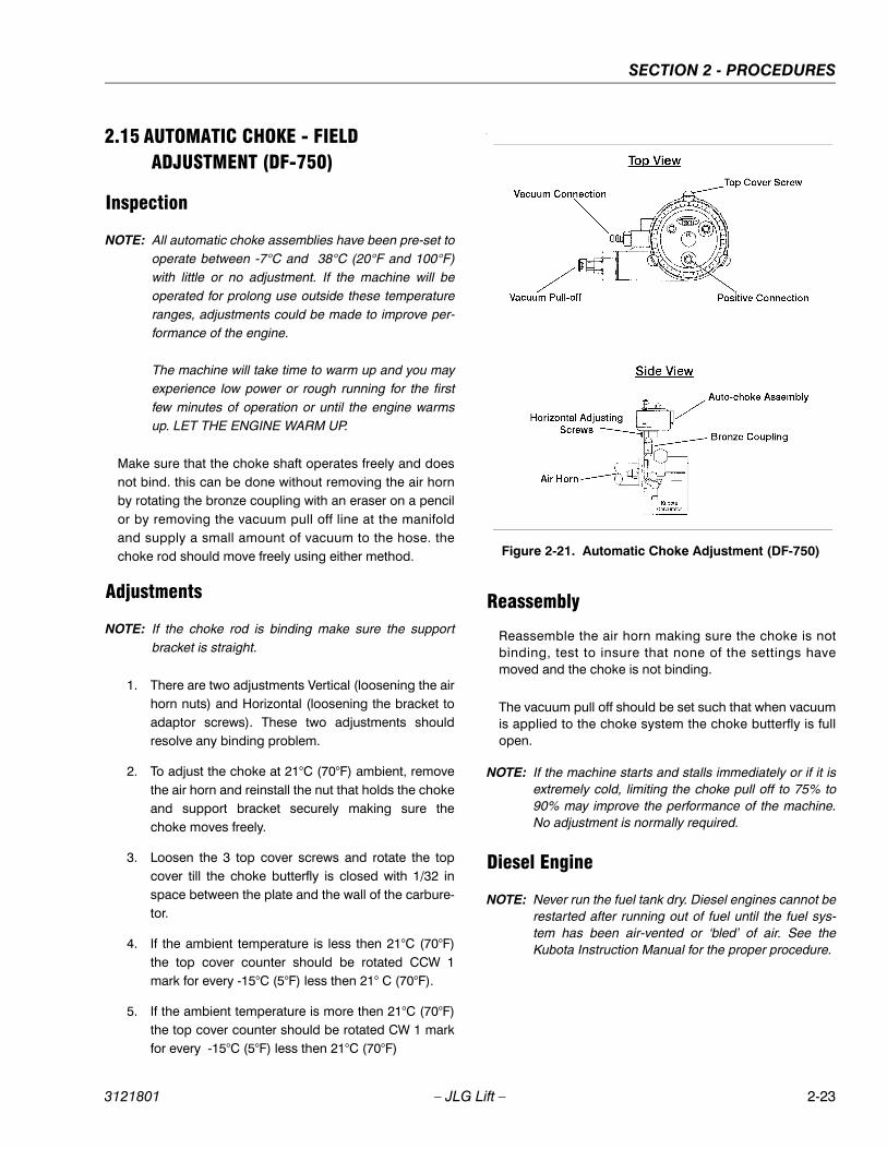
SECTION 2 - PROCEDURES
2.15 AUTOMATIC CHOKE - FIELD ADJUSTMENT (DF-750)
Inspection
NOTE: All automatic choke assemblies have been pre-set tooperate between -7°C and 38°C (20°F and 100°F)with little or no adjustment. If the machine will beoperated for prolong use outside these temperatureranges, adjustments could be made to improve per-formance of the engine.
The machine will take time to warm up and you mayexperience low power or rough running for the firstfew minutes of operation or until the engine warmsup. LET THE ENGINE WARM UP.
Make sure that the choke shaft operates freely and doesnot bind. this can be done without removing the air hornby rotating the bronze coupling with an eraser on a pencilor by removing the vacuum pull off line at the manifoldand supply a small amount of vacuum to the hose. thechoke rod should move freely using either method.
Adjustments
NOTE: If the choke rod is binding make sure the supportbracket is straight.
1. There are two adjustments Vertical (loosening the airhorn nuts) and Horizontal (loosening the bracket toadaptor screws). These two adjustments shouldresolve any binding problem.
2. To adjust the choke at 21°C (70°F) ambient, removethe air horn and reinstall the nut that holds the chokeand support bracket securely making sure thechoke moves freely.
3. Loosen the 3 top cover screws and rotate the topcover till the choke butterfly is closed with 1/32 inspace between the plate and the wall of the carbure-tor.
4. If the ambient temperature is less then 21°C (70°F)the top cover counter should be rotated CCW 1mark for every -15°C (5°F) less then 21° C (70°F).
5. If the ambient temperature is more then 21°C (70°F)the top cover counter should be rotated CW 1 markfor every -15°C (5°F) less then 21°C (70°F)
.
Reassembly
Reassemble the air horn making sure the choke is notbinding, test to insure that none of the settings havemoved and the choke is not binding.
The vacuum pull off should be set such that when vacuumis applied to the choke system the choke butterfly is fullopen.
NOTE: If the machine starts and stalls immediately or if it isextremely cold, limiting the choke pull off to 75% to90% may improve the performance of the machine.No adjustment is normally required.
Diesel Engine
NOTE: Never run the fuel tank dry. Diesel engines cannot berestarted after running out of fuel until the fuel sys-tem has been air-vented or ‘bled’ of air. See theKubota Instruction Manual for the proper procedure.
Figure 2-21. Automatic Choke Adjustment (DF-750)
3121801 – JLG Lift – 2-23
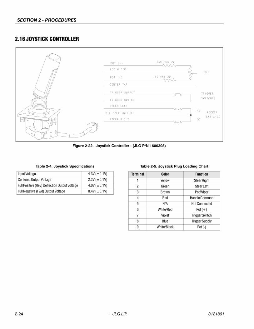
SECTION 2 - PROCEDURES
2.16 JOYSTICK CONTROLLER
Figure 2-22. Joystick Controller - (JLG P/N 1600308)
Table 2-4. Joystick Specifications
Input Voltage 4.3V (±0.1V)
Centered Output Voltage 2.2V (±0.1V)
Full Positive (Rev) Deflection Output Voltage 4.0V (±0.1V)
Full Negative (Fwd) Output Voltage 0.4V (±0.1V)
Table 2-5. Joystick Plug Loading Chart
Terminal Color Function
1 Yellow Steer Right
2 Green Steer Left
3 Brown Pot Wiper
4 Red Handle Common
5 N/A Not Connected
6 White/Red Pot (+)
7 Violet Trigger Switch
8 Blue Trigger Supply
9 White/Black Pot (-)
2-24 – JLG Lift – 3121801

SECTION 2 - PROCEDURES
Figure 2-23. Joystick Controller - (JLG P/N 1600403)
Table 2-6. Joystick Specifications
Input Voltage 5V
Centered Output Voltage 4.25V to 2.60V
Reverse Voltage 4.60V to 4.80V
Forward Voltage 0.40V to 0.60V
Table 2-7. Joystick Plug Loading Chart
Terminal Color Function
1 Yellow Steer Right
2 Green Steer Left
3 Brown Pot Wiper
4 Red Handle Common
5 N/A Not Connected
6 White/Red Pot (+)
7 Violet Trigger Switch
8 Blue Trigger Supply
9 White/Black Pot (-)
3121801 – JLG Lift – 2-25
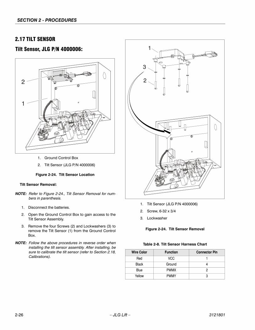
SECTION 2 - PROCEDURES
2.17 TILT SENSOR
Tilt Sensor, JLG P/N 4000006:
Tilt Sensor Removal:
NOTE: Refer to Figure 2-24., Tilt Sensor Removal for num-bers in parenthesis.
1. Disconnect the batteries.
2. Open the Ground Control Box to gain access to theTilt Sensor Assembly.
3. Remove the four Screws (2) and Lockwashers (3) toremove the Tilt Sensor (1) from the Ground ControlBox.
NOTE: Follow the above procedures in reverse order wheninstalling the tilt sensor assembly. After installing, besure to calibrate the tilt sensor (refer to Section 2.18,Calibrations).
1
2
1. Ground Control Box
2. Tilt Sensor (JLG P/N 4000006)
Figure 2-24. Tilt Sensor Location
Table 2-8. Tilt Sensor Harness Chart
Wire Color Function Connector Pin
Red VCC 1
Black Ground 4
Blue PWMX 2
Yellow PWMY 3
1
3
2
1. Tilt Sensor (JLG P/N 4000006)
2. Screw, 6-32 x 3/4
3. Lockwasher
Figure 2-24. Tilt Sensor Removal
2-26 – JLG Lift – 3121801

SECTION 2 - PROCEDURES
Tilt Sensor, JLG P/N 4000021:
Tilt Sensor Removal:
NOTE: Refer to Figure 2-26., Tilt Sensor Removal for num-bers in parenthesis.
1. Disconnect the batteries.
2. Open the Ground Control Box to gain access to theTilt Sensor Assembly.
3. Remove the four Screws (3), Lockwashers (4),Standoff Insulators (5), and Washers (6) to removethe Tilt Sensor (1) and Sensor Mount (2) from theGround Control Box.
4. The Tilt Sensor (1) can be removed from the SensorMount (2) by removing the three Screws (7).
NOTE: Follow the above procedures in reverse order wheninstalling the tilt sensor assembly. After installing, besure to calibrate the tilt sensor (refer to Section 2.18,Calibrations).
2
1
4. Ground Control Box
5. Tilt Sensor Assembly (JLG P/N 1810140)
Figure 2-25. Tilt Sensor Location
Table 2-9. Tilt Sensor Harness
Wire Color Function Connector Pin
Red VCC 1
Green PWMX 2
White PWMY 3
Black Ground 4
1
2
3
5
6
4
7
1. Tilt Sensor (JLG P/N 4000021)
2. Sensor Mount
3. Screw, 6-32 x 1
4. Lockwasher
5. Standoff Insulator
6. Washer, 0.313 x 0.250 Nylon
7. Screw, M3.5 x 0.6 x 10
Figure 2-26. Tilt Sensor Removal
3121801 – JLG Lift – 2-27

SECTION 2 - PROCEDURES
2.18 CALIBRATIONS
Tilt Sensor Calibration:
1. Drive the machine onto a measured level surface(±0.5° for both x and y axis).
2. Using the Analyzer, go to MENU: CALIBRATION;TILT SENSOR. Press Enter. LEVEL VEHICLE will dis-play. Press Enter again to calibrate.
3. Both axis’ raw angles need to be within ±5.0°, other-wise the machine is to unlevel and the software willprohibit calibration. Should this occur, attempt todissect the three areas of error to find the primarycontributor:
a. Machine mounting and/or grade:With a digital level, measure the top of theGround Control box for levelness. If unable toget a good reading, check the box’s mountingsurface for levelness.
b. Tilt sensor mounting on machine or wedgedcrooked in control box:If the machine mounting/grade appears accept-able, open the Ground Control box carefully.Observe whether the tilt sensor is properlyseated.
c. Tilt sensor has developed an offset shift:Remove the tilt sensor from the Ground Controlbox, but keep both the tilt sensor and GroundControl box electrically connected. Level oneaxis of the tilt sensor and observe the raw read-ing (should be within ±2.0°). Do the same for theother axis. If either axis is greater than ±2.0°,replace the tilt sensor.
Some possible reasons that the tilt sensor will not cali-brate are:
a. The surface the machine is sitting on is off levelby a few degrees (flat doesn’t imply level; park-ing lots are often not level).
b. The tilt sensor has failed one or both of thechannels (X axis and Y axis).
c. Tilt sensor has moisture intrusion that hasshifted its output.
d. Water and/or corrosion in the box has corruptedelectrical connections or caused a tilt sensor orground control board failure (observe anycracks in the box).
2
1
1. Ground Control Box
2. Digital Level
2
1
1. Ground Control Box
2. Tilt Sensor
2-28 – JLG Lift – 3121801
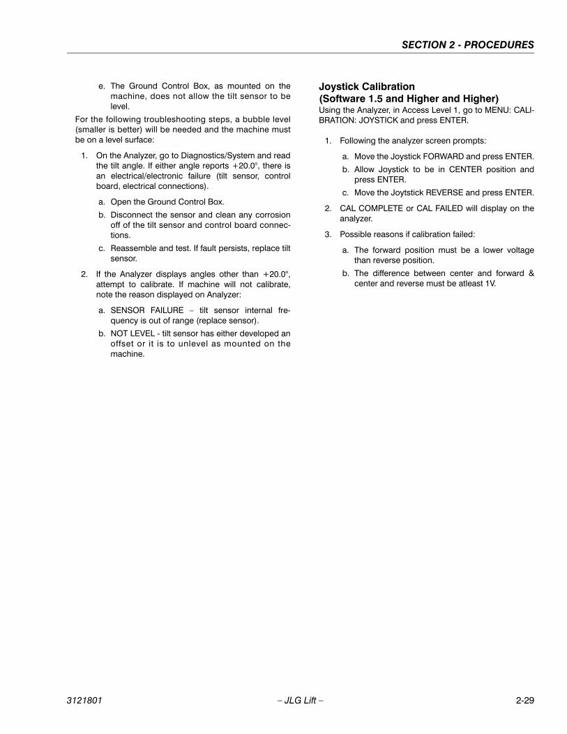
SECTION 2 - PROCEDURES
e. The Ground Control Box, as mounted on themachine, does not allow the tilt sensor to belevel.
For the following troubleshooting steps, a bubble level(smaller is better) will be needed and the machine mustbe on a level surface:
1. On the Analyzer, go to Diagnostics/System and readthe tilt angle. If either angle reports +20.0°, there isan electrical/electronic failure (tilt sensor, controlboard, electrical connections).
a. Open the Ground Control Box.
b. Disconnect the sensor and clean any corrosionoff of the tilt sensor and control board connec-tions.
c. Reassemble and test. If fault persists, replace tiltsensor.
2. If the Analyzer displays angles other than +20.0°,attempt to calibrate. If machine will not calibrate,note the reason displayed on Analyzer:
a. SENSOR FAILURE – tilt sensor internal fre-quency is out of range (replace sensor).
b. NOT LEVEL - tilt sensor has either developed anoffset or it is to unlevel as mounted on themachine.
Joystick Calibration(Software 1.5 and Higher and Higher)Using the Analyzer, in Access Level 1, go to MENU: CALI-BRATION: JOYSTICK and press ENTER.
1. Following the analyzer screen prompts:
a. Move the Joystick FORWARD and press ENTER.
b. Allow Joystick to be in CENTER position andpress ENTER.
c. Move the Joytstick REVERSE and press ENTER.
2. CAL COMPLETE or CAL FAILED will display on theanalyzer.
3. Possible reasons if calibration failed:
a. The forward position must be a lower voltagethan reverse position.
b. The difference between center and forward ¢er and reverse must be atleast 1V.
3121801 – JLG Lift – 2-29

SECTION 2 - PROCEDURES
2.19 ELECTRONIC CONTROL SYSTEM
Hand Held Analyzer
To Connect the Hand Held Analyzer1. Connect the four pin end of the cable supplied with
the analyzer, to the top connection of the motor con-troller and connect the remaining end of the cable tothe analyzer.
NOTE: The cable has a four pin connector at each end ofthe cable; the cable cannot be connected back-wards.
2. Power up the Control System by turning the lowerkey to the platform position and pulling both emer-gency stop buttons on.
menu: PRESS ENTERHELP:Analyzer Display
Escape KeyTo return home or access
previous menu
Enter KeyStores and selects Top Level, Sub
Level, and item menus
Left & Right Arrow KeysUsed to move between Top Level,
Sub Level, and item menus
Up & Down Arrow KeysValue Selector
Figure 2-27. Hand Held Analyzer
2-30 – JLG Lift – 3121801

SECTION 2 - PROCEDURES
Using the Analyzer
With the machine power on and the analyzer connectedproperly, the analyzer will display the following:
HELP:
PRESS ENTER
At this point, using the RIGHT and LEFT arrow keys, youcan move between the top level menu items. To select adisplayed menu item, press ENTER. To cancel a selectedmenu item, press ESC; then you will be able to scrollusing the right and left arrow keys to select a differentmenu item.
The top level menus are as follows:
HELP
DIAGNOSTICS
ACTIVATE TESTS
ACCESS LEVEL
PERSONALITIES
MACHINE SETUP
LEVEL VEHICLE
If you press ENTER, at the HELP:PRESS ENTER display,and a fault is present during power up, the analyzer dis-play will scroll the fault across the screen. If there was nofault detected during power up, the display will read:HELP: EVERYTHING OK
If ENTER is pressed again, the display moves to the fol-lowing display:
LOGGED HELP
1: STARTUP (2/1)
At this point, the analyzer will display the current fault, ifany are present. You may scroll through the fault logs toview what the last 15 faults were. Use the right and leftarrow keys to scroll through the fault logs. To return to thebeginning, press ESC two times.
When a top level menu is selected, a new set of menuitems may be offered; for example:
PLATFORM
DRIVE
LIFT SEL
SPEED SEL
HORN
ENGINE START
FUEL/GLOW
STEER LEFT
STEER RIGHT
JOYSTICK
Pressing ENTER with any of the above displayed menus,will display additional sub-menus within the selectedmenu. In some cases the next level is the parameter orinformation to be changed. Refer to the flow chart for whatmenus are available within the top level menus. You mayonly view the personality settings for selected menus
MENU:HELP:PRESS ENTER
l og: (211)
3121801 – JLG Lift – 2-31

SECTION 2 - PROCEDURES
while in access level 2. Remember, you may always can-cel a selected menu item by pressing the ESC key.
Changing the Access Level of the Hand Held Analyzer
When the analyzer is first connected, you will be in accesslevel 2 which enables you to only view most configurationsettings which cannot be changed until you enter a pass-word to advance to a lower level. This ensures that a set-ting cannot be accidentally altered. To change the accesslevel, the correct password must be entered. To enter thepassword, scroll to the ACCESS LEVEL menu. For exam-ple:
MENU:
ACCESS LEVEL 2
Press ENTER to select the ACCESS LEVEL menu.
Using the UP or DOWN arrow keys, enter the first digit ofthe password, 3.
Then using the RIGHT arrow key, position the cursor tothe right one space to enter the second digit of the pass-word.
Use the UP or DOWN arrow key to enter the second digitof the password which is 3.
Repeat this process until you have entered all five digits ofthe password which is 33271.
Once the correct password is displayed, press ENTER.
The access level should display the following, if the pass-word was entered correctly:
MENU:
ACCESS LEVEL 1
Repeat the above steps if the correct access level is notdisplayed or you can not adjust the personality settings.
MENU: ACCESS LEVEL 2
MENU: ACCESS LEVEL 1
2-32 – JLG Lift – 3121801

SECTION 2 - PROCEDURES
Adjusting Parameters Using the Hand Held Analyzer
Once you have gained access to level 1, and a personalityitem is selected, press the UP or DOWN arrow keys toadjust its value, for example:
PERSONALITIES:DRIVE ACCEL 4.0s
There will be a minimum and maximum for the value toensure efficient operation. The Value will not increase ifthe UP arrow is pressed when at the maximum value norwill the value decrease if the DOWN arrow is pressed andthe value is at the minimum value for any particular per-sonality. If the value does not change when pressing theup and down arrows, check the access level to ensureyou are at access level 1.
Machine Setup
When a machine digit item is selected, press the UP orDOWN arrow keys to adjust its value, for example:
FAILURE TO MAKE THE PROPER SETTINGS FOR THE PARTICU-
LAR MACHINE CAN RESULT IN IMPROPER OPERATION.
CHANGING THESE SETTINGS MAY ADVERSELY AFFECT THE
PERFORMANCE OF THE MACHINE.
LEVELING JACKS:1=YES
The effect of the machine digit value is displayed alongwith its value. The above display would be selected if themachine was equipped with a ground alarm and youwanted it to sound when driving. There are certain set-tings allowed to install optional features or select themachine model.
When selecting the machine model to match the size ofthe machine, the personality settings will return to defaultsettings.
NOTE: Refer to the appropriate Machine Personality Set-tings Table, and the Machine Setup Table in the JLGService Manual for the recommended factory set-tings.
Password 33271 will give you access to level 1,which will permit you to change all machine person-ality settings.
IT IS A GOOD PRACTICE TO AVOID PRESSURE-WASHING ELEC-
TRICAL/ELECTRONIC COMPONENTS. SHOULD PRESSURE-WASHING BE UTILIZED TO WASH AREAS CONTAINING ELECTRI-
CAL/ELECTRONIC COMPONENTS, JLG INDUSTRIES, INC. REC-OMMENDS A MAXIMUM PRESSURE OF 750 PSI (52 BAR) AT AMINIMUM DISTANCE OF 12 INCHES (30.5 CM) AWAY FROM THESE
COMPONENTS. IF ELECTRICAL/ELECTRONIC COMPONENTSARE SPRAYED, SPRAYING MUST NOT BE DIRECT AND BE FORBRIEF TIME PERIODS TO AVOID HEAVY SATURATION.
PERSONALITIES: DRIVE ACCEL 4.0s
l evel ing j acks: 1=yes
3121801 – JLG Lift – 2-33

SECTION 2 - PROCEDURES
2.20 FLASH CODES AND DESCRIPTIONS
Table 2-10. Help Messages and Flash Codes - Software P1.X
FLASH CODE HELP MESSAGES AND FLASH CODES
No Flash Code EVERYTHING OK
GROUND MODE OK
ALARM SOUNDING - TILTED & ABOVE ELEVATIONPlatform is elevated and the chassis is not level.
DIFFERENT FUNCTION SELECTED & IGNOREDA function (i.e. Drive, Lift, etc.) is active and the operator has selected another function. The system has ignored the new selection.
DRIVING AT CUTBACK - ABOVE ELEVATIONPlatform is elevated and the machine is in the drive mode of operation.
FUNCTION SELECTED BUT TRIGGER SWITCH OPENA function (i.e. Drive, Lift, etc.) has been selected by the operator, but the trigger switch is not active (closed).
JOYSTICK MOVED BUT NO FUNCTION SELECTEDThe joystick was moved out of the center position before a function was selected.
DRIVE PREVENTED - ABOVE DRIVE CUTOUT HEIGHTMachin is elevated above the drive cutout height.
2-1 STARTUPA new system power up has occurred since the last help message.
2-2 FUNCTIONS LOCKED OUT - SHORT TO PLATFORM ROW INPUT DETECTED Battery power has been detected on a row input (pins J1-8, J1-9, or J1-13).
FUNCTION PROBLEM - DRIVE PERMANENTLY SELECTEDDrive select switch in the platform control box closed at start up or for more than ten seconds. Release switch to clear fault.
FUNCTION PROBLEM - LIFT PERMANENTLY SELECTEDLift select switch in the platform control box closed at start up or for more than ten seconds. Release switch to clear fault
FUNCTION PROBLEM - O/R or L/J PERMANENTLY SELECTEDAn outrigger select switch in the platform control box closed at start up or for more than ten seconds. Release switch to clear fault
FUNCTION PROBLEM - START PERMANENTLY SELECTEDStart switch in the platform control box closed at start up. Release switch to clear fault
FUNCTION PROBLEM - GLOW PLUG PERMANENTLY SELECTEDGlow plug switch in the platform control box closed at start up. Release switch to clear fault
FUNCTION PROBLEM - STEER LEFT PERMANENTLY SELECTEDSteer left switch in the platform control box closed at start up. Release switch to clear fault
FUNCTION PROBLEM - STEER RIGHT PERMANENTLY SELECTEDSteer right switch in the platform control box closed at start up. Release switch to clear fault
FUNCTION PROBLEM - HORN PERMANENTLY SELECTEDHorn switch in platform control box closed at start up. Release switch to clear fault.
FUNCTION PROBLEM - JOYSTICK CALIBRATIONFAULTYThe Personalities for theJoystick are improperly adjusted or a joystick calibration attempt failed. Re-adjust or recalibrate.
JOYSTICK FAULTY - WIPER OUT OF RANGEThe joystick wiper signal input is outside the acceptable voltage range. The wiper wire being off, the wiper wire shorted to battery power, or the wiper wire shorted to battery negative could cause this.
JOYSTICK FAULTY - STEER SWITCHES ACTIVE TOGETHERBoth the steer left and steer right inputs are closed at the same time. A short in the steer switch wiring or a failed steer switch can cause this.
FUNCTION LOCKED OUT - JOYSTICK NOT CENTEREDSelected function is not allowed because the joystick is not centered. Return joystick to center and reselect function.
FUNCTION PROBLEM - JOYSTICK CALIBRATION FAULTYThe Personalities for theJoystick are improperly adjusted or a joystick calibration attempt failed. Re-adjust or recalibrate
2-34 – JLG Lift – 3121801

SECTION 2 - PROCEDURES
2-2 FUNCTION PROBLEM - TRIGGER PERMANENTLY CLOSEDTrigger switch in the platform control box closed at start up. Release switch to clear fault.
TRIGGER CLOSED TOO LONG WHILE IN NEUTRALTrigger switch in the platform control box closed for more than ten seconds while the joystick is in the neutral position. Release switch to clear fault.
2-3 FUNCTION PROBLEM - LIFT PERMANENTLY SELECTEDLift switch (up or down) in the ground control box closed at start up. Release switch to clear fault
FUNCTION PROBLEM - START PERMANENTLY SELECTEDStart switch in the ground control box closed at start up. Release switch to clear fault
FUNCTION PROBLEM - GLOW PLUG PERMANENTLY SELECTEDGlow plug switch in the ground control box closed at start up. Release switch to clear fault
NO DATA FROM TILT SENSOR - NOT CONNECTED OR FAULTYNo signal from the tilt switch. Check wiring and plug connections at the level sensor and at the ground control board.
2-5 DRIVE & LIFTUP PREVENTED - OSC AXLE NOT SET
DRIVE & LIFTUP PREVENTED - FUNCTION CUTOUT ACTIVE
ALL FUNCTIONS PREVENTED - FUNCTION CUTOUT ACTIVE
PLATFORM OVERLOAD
ELEV PROX PERMANENTLY CLOSED - CHECK PROX & CAM SWITCH ADJUSTMENT
LEVEL PREVENTED - CHASSIS TILTED EXCESSIVELY
2-6 FRONT LEFT LEVELING JACK SHORT TO GROUND
FRONT RIGHT LEVELING JACK SHORT TO GROUND
REAR LEFT LEVELING JACK SHORT TO GROUND
REAR RIGHT LEVELING JACK SHORT TO GROUND
FRONT LEFT LEVELING JACK SHORT TO BATTERY
FRONT RIGHT LEVELING JACK SHORT TO BATTERY
REAR LEFT LEVELING JACK SHORT TO BATTERY
REAR RIGHT LEVELING JACK SHORT TO BATTERY
3-3 OUTPUT ENERGIZED EXTERNALLY - CHECK WIRING
OUTPUT SHORTED - CHECK WIRING
4-4 BATTERY VOLTAGE TOO LOWBattery voltage below 8.0V. Check battery and alternator.
BATTERY VOLTAGE TOO HIGHBattery voltage above 16V. Check battery and alternator.
5-5 ENGINE SHUTDOWN — OVERSPEEDThe engine speed exceeded 4500 RPM for more than 2 seconds. Check throttle actuator for debris or interference, which prevents free movement of actuator. Recycle power to clear the fault and restart.
ENGINE SHUTDOWN - OIL PRES / COOLANT TEMPThe engine oil pressure was too low or the engine coolant temperature was too high for more than 10 seconds. Check engine fluid levels. Recycle power to clear fault and restart.
6-6 COMMUNICATION FAILURE: I/O MODULE
Table 2-10. Help Messages and Flash Codes - Software P1.X
FLASH CODE HELP MESSAGES AND FLASH CODES
3121801 – JLG Lift – 2-35
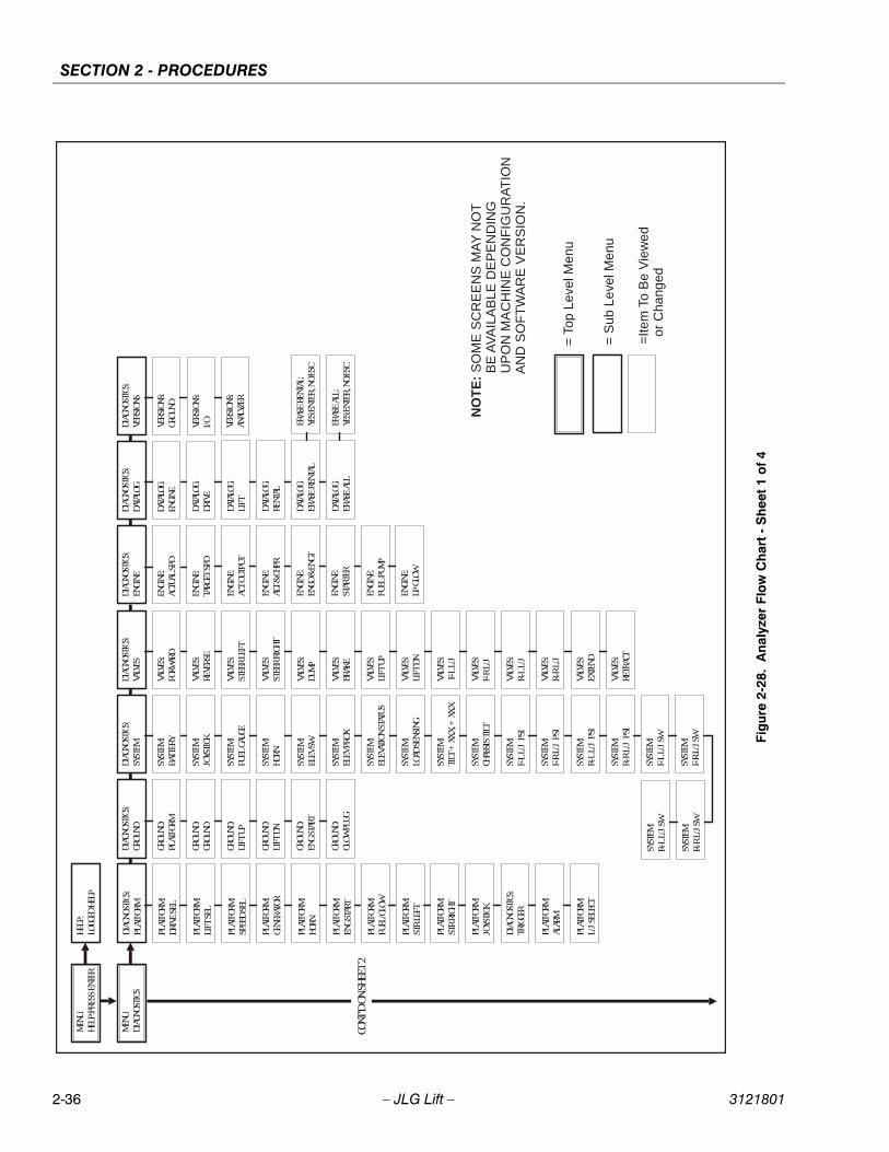
SECTION 2 - PROCEDURES
M
ENU:
DIAG
NOST
ICS
DIAG
NOST
ICS:
GROU
ND
GROU
ND:
PLAT
FORM
GROU
ND:
GROU
ND
GROU
ND:
LIFT
UP
GROU
ND:
LIFT
DN
GROU
ND:
ENG
STAR
T
DIAG
NOST
ICS:
SYST
EM
SYST
EM:
BATT
ERY
DIAG
NOST
ICS:
VALV
ES
VALV
ES:
FORW
ARD
SYST
EM:
JOYS
TICK
SYST
EM:
FUEL
GAU
GE
SYST
EM:
HORN
MEN
U:HE
LP:P
RESS
ENT
ERHE
LP:
LOGG
ED H
ELP
DIAG
NOST
ICS:
PLAT
FORM
PLAT
FORM
:DR
IVE
SEL
PLAT
FORM
:LI
FT S
EL
PLAT
FORM
:SP
EED
SEL
PLAT
FORM
:GE
NERA
TOR
PLAT
FORM
:HO
RN
PLAT
FORM
:EN
G ST
ART
PLAT
FORM
:FU
EL/G
LOW
PLAT
FORM
:ST
R LE
FT
PLAT
FORM
:ST
R RI
GHT
PLAT
FORM
:JO
YSTI
CK
DIAG
NOST
ICS:
TRIG
GER
PLAT
FORM
:AL
ARM
PLAT
FORM
:L/
J SE
LECT
GROU
ND:
GLOW
PLU
G
SYST
EM:
ELEV
SW
SYST
EM:
ELEV
PRO
X
SYST
EM:
ELEV
ATIO
N ST
ATUS
SYST
EM:
LOAD
SEN
SING
SYST
EM:
TILT
+XX
.X, +
XX.X
SYST
EM:
CHAS
SIS
TILT
SYST
EM:
F-L
L/J
PSI
SYST
EM:
F-R
L/J
PSI
SYST
EM:
R-L
L/J
PSI
SYST
EM:
R-R
L/J
PSI
SYST
EM:
F-L
L/J
SW
SYST
EM:
F-R
L/J
SW
VALV
ES:
REVE
RSE
VALV
ES:
STEE
R LE
FT
VALV
ES:
STEE
R RI
GHT
VALV
ES:
DUM
P
VALV
ES:
BRAK
E
VALV
ES:
LIFT
UP
VALV
ES:
LIFT
DN
VALV
ES:
F-L
L/J
VALV
ES:
F-R
L/J
VALV
ES:
R-L
L/J
VALV
ES:
R-R
L/J
VALV
ES:
EXTE
ND
VALV
ES:
RETR
ACT
DIAG
NOST
ICS:
ENGI
NE
ENGI
NE:
ACTU
AL S
PD
ENGI
NE:
TARG
ET S
PD
DIAG
NOST
ICS:
DATA
LOG
DATA
LOG:
ENGI
NE
DIAG
NOST
ICS:
VERS
IONS
VERS
IONS
:GR
OUND
ENGI
NE:
ALT
& CH
PR
ENGI
NE:
ENGO
& E
NGT
ENGI
NE:
STAR
TER
ENGI
NE:
ACT
OUTP
UT
ENGI
NE:
FUEL
PUM
P
ENGI
NE:
LP G
LOW
DATA
LOG:
DRIV
E
DATA
LOG:
RENT
AL
DATA
LOG:
ERAS
E RE
NTAL
DATA
LOG:
LIFT
VERS
IONS
:I/O VE
RSIO
NS:
ANAL
YZER
NO
TE
: S
OM
E S
CR
EE
NS
MA
Y N
OT
BE
AV
AIL
AB
LE D
EP
EN
DIN
G
UP
ON
MA
CH
INE
CO
NF
IGU
RA
TIO
N
A
ND
SO
FT
WA
RE
VE
RS
ION
.
= T
op L
evel
Me
nu
= S
ub L
eve
l Men
u
=It
em T
o B
e V
iew
ed
or
Cha
nged
SYST
EM:
R-L
L/J
SW
SYST
EM:
R-R
L/J
SW
DATA
LOG:
ERAS
E AL
L
ERAS
E RE
NTAL
:YE
S:EN
TER,
NO:
ESC
ERAS
E AL
L:YE
S:EN
TER,
NO:
ESC
CONT
’D O
N SH
EET
2
Fig
ure
2-28
. A
naly
zer
Flo
w C
har
t -
Sh
eet 1
of
4
2-36 – JLG Lift – 3121801

SECTION 2 - PROCEDURES
MEN
U:AC
TIVA
TE T
ESTS
RUN
SYST
EM T
EST
YES:
ENTE
R, N
O:ES
C
CLOS
E TR
IGGE
ROP
EN T
RIGG
ERTE
ST V
LV &
ENG
?
FORW
ARD
TEST
PLA
TFRM
SW
?
CLOS
E DR
IVE
SEL
OPEN
DRI
VE S
EL
CLOS
E LI
FT S
ELOP
EN L
IFT
SEL
TEST
LED
S &
ALRM
?TE
ST G
ROUN
D SW
?
CLOS
E ST
ART
OPEN
STA
RT
CLOS
E GL
OW P
LUG
OPEN
BLO
W P
LUG
CLOS
E LI
FT U
POP
EN L
IFT
UP
CLOS
E LI
FT D
OWN
OPEN
LIF
T DO
WN
CONT
’D O
N SH
EET
3
REVE
RSE
LEFT
STE
ER
RIGH
T ST
EER
DUM
P
LIFT
UP
FUEL
PUM
P
LP/G
LOW
ACTU
ATOR
F-L
L/J
F-R
L/J
R-L
L/J
R-R
L/J
CLOS
E ST
ART
OPEN
STA
RT
CLOS
E HO
RNOP
EN H
ORN
CLOS
E SP
EED
SEL
OPEN
SPE
ED S
EL
CLOS
E FU
EL S
ELOP
EN F
UEL
SEL
FROM
SHE
ET 1
NO
TE
: S
OM
E S
CR
EE
NS
MA
Y N
OT
BE
AV
AIL
AB
LE D
EP
EN
DIN
G
UP
ON
MA
CH
INE
CO
NF
IGU
RA
TIO
N
A
ND
SO
FT
WA
RE
VE
RS
ION
.
= T
op L
evel
Men
u
= S
ub L
eve
l Men
u
=Ite
m T
o B
e V
iew
ed o
r C
han
ged
TEST
PRO
P CN
TLR?
CNTL
TO
CENT
ER
CNTL
FW
D TO
MAX
TEST
S CO
MPL
ETE
EXTE
ND
RETR
ACT
CLOS
E GL
OW P
LUG
OPEN
GLO
W P
LUG
CLOS
E LE
FT S
TEER
OPEN
LEF
T ST
EER
CLOS
E RI
GHT
STR
OPEN
RIG
HT S
TR
CLOS
E L/
J SE
LOP
EN L
/J S
EL
CNTL
FW
D TO
MIN
CNTL
BAC
K TO
MAX
CNTL
BAC
K TO
MIN
DRIV
E SE
L ON
?
LIFT
SEL
ON?
FUEL
GAU
GE O
N?
TILT
ON?
SYS
DIST
RESS
ON?
L/J
SET
ON?
L/J
SELE
CT O
N?
L/J
STOW
ED O
N?
ALAR
M S
OUND
ING?
Fig
ure
2-29
. A
naly
zer
Flo
w C
har
t -
Sh
eet 2
of
4
3121801 – JLG Lift – 2-37

SECTION 2 - PROCEDURES
MEN
U:AC
CESS
LEV
EL 1
MEN
U:PE
RSON
ALIT
IES
ACCE
SS L
EVEL
:CO
DE 0
0000
PERS
ONAL
ITIE
S:DR
IVE
DRIV
E:AC
CEL
DRIV
E:DE
CEL
DRIV
E:FW
D M
IN
DRIV
E:FW
D M
AX
DRIV
E:FW
D EL
EV
DRIV
E:RE
V M
IN
DRIV
E:RE
V M
AX
DRIV
E:RE
V EL
EV
DRIV
E:LO
MAX
DRIV
E:EN
GINE
SPD
PERS
ONAL
ITIE
S:LI
FT
LIFT
:AC
CEL
LIFT
:DE
CEL
LIFT
:UP
MIN
ENG
LIFT
:UP
MAX
ENG
LIFT
:LO
MAX
LIFT
:GA
IN
LIFT
:DR
OOP
LIFT
:ST
ABIL
ITY
PERS
ONAL
ITIE
S:ID
LE
IDLE
:EN
GINE
SPD
PERS
ONAL
ITIE
S:JO
YSTI
CK
JOYS
TICK
:FW
D M
AX
JOYS
TICK
:FW
D M
IN
JOYS
TICK
:RE
V M
IN
JOYS
TICK
:RE
V M
AX
CONT
’D O
N SH
EET
4
DRIV
E:GA
IN
DRIV
E:DR
OOP
DRIV
E:ST
ABIL
ITY
IDLE
:GA
IN
IDLE
:DR
OOP
IDLE
:ST
ABIL
ITY
IDLE
:M
IN A
CT
IDLE
:M
AX A
CT L
/D
IDLE
:M
AX A
CT ID
L
IDLE
:CU
T AC
T
IDLE
:GE
N EN
G SP
D
FROM
SHE
ET 2
NO
TE
: S
OM
E S
CR
EE
NS
MA
Y N
OT
BE
AV
AIL
AB
LE D
EP
EN
DIN
G
UP
ON
MA
CH
INE
CO
NF
IGU
RA
TIO
N
A
ND
SO
FT
WA
RE
VE
RS
ION
.
= T
op L
evel
Men
u
= S
ub L
eve
l Men
u
=Ite
m T
o B
e V
iew
ed
or
Ch
ange
d
Fig
ure
2-30
. A
nal
yzer
Flo
w C
har
t - S
hee
t 3 o
f 4
2-38 – JLG Lift – 3121801

SECTION 2 - PROCEDURES
MEN
U:M
ACHI
NE S
ETUP
MOD
EL:
0=26
0MRT
GAS
/LP
MOD
EL:
1=26
0MRT
DIE
SEL
MAR
KET:
0=AN
SI
MAR
KET:
1=AN
SI E
XPOR
T
LEVE
LING
JACK
S:0=
NO
LEVE
LING
JACK
S:1=
YES
LOAD
:0=
NONE
LOAD
:1=
CUTO
UT P
LT
LOAD
:2=
CUTO
UT A
LL
FROM
SHE
ET 3
MAR
KET:
2=CS
A
MAR
KET:
3=CE
MAR
KET:
4=AU
STRA
LIA
MEN
U:CA
LIBR
ATIO
NSCA
LIBR
ATIO
NS:
TILT
SEN
SOR
LEVE
L VE
HICL
E:YE
S: E
NTER
, NO:
ESC
CALI
BRAT
IONS
:JO
YSTI
CK
JOYS
TICK
:YE
S: E
NTER
, NO:
ESC
LEVE
LING
JACK
S:2=
YES
SPL
LENG
TH
LEVE
L VE
HICL
E:TI
LT +
XX.X
, +XX
.X
LEVE
L VE
HICL
E:(S
ENSO
R FA
ILUR
E)
LEVE
L VE
HICL
E:(N
OT L
EVEL
)
JOYS
TICK
:FO
RWAR
D &
ENTE
R
JOYS
TICK
:CE
NTER
& E
NTER
JOYS
TICK
:RE
VERS
E &
ENTE
R
JOYS
TICK
:CA
L CO
MPL
ETE
JOYS
TICK
:CA
L FA
ILED
NO
TE
: S
OM
E S
CR
EE
NS
MA
Y N
OT
BE
AV
AIL
AB
LE D
EP
EN
DIN
G
UP
ON
MA
CH
INE
CO
NF
IGU
RA
TIO
N
A
ND
SO
FT
WA
RE
VE
RS
ION
.
= T
op L
eve
l Me
nu
= S
ub L
eve
l Men
u
=Ite
m T
o B
e V
iew
ed
or
Cha
nge
d
Fig
ure
2-31
. A
naly
zer
Flo
w C
har
t -
Sh
eet
4 o
f 4
3121801 – JLG Lift – 2-39
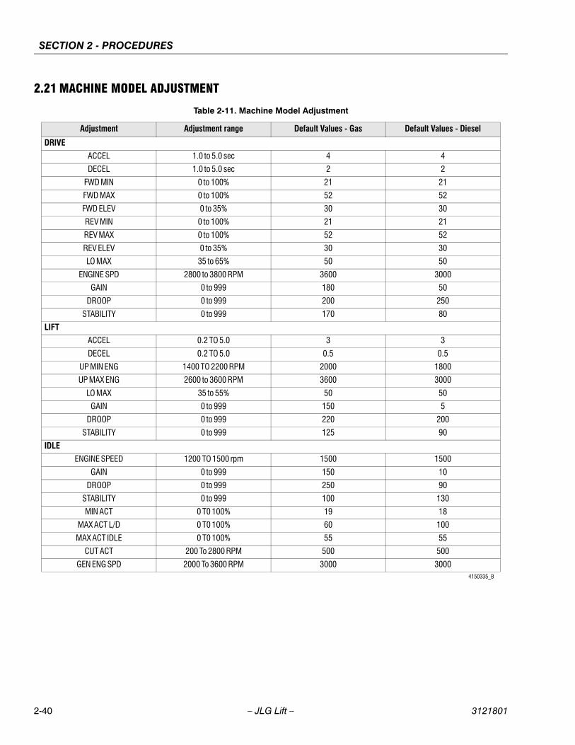
SECTION 2 - PROCEDURES
2.21 MACHINE MODEL ADJUSTMENT
Table 2-11. Machine Model Adjustment
Adjustment Adjustment range Default Values - Gas Default Values - Diesel
DRIVE
ACCEL 1.0 to 5.0 sec 4 4
DECEL 1.0 to 5.0 sec 2 2
FWD MIN 0 to 100% 21 21
FWD MAX 0 to 100% 52 52
FWD ELEV 0 to 35% 30 30
REV MIN 0 to 100% 21 21
REV MAX 0 to 100% 52 52
REV ELEV 0 to 35% 30 30
LO MAX 35 to 65% 50 50
ENGINE SPD 2800 to 3800 RPM 3600 3000
GAIN 0 to 999 180 50
DROOP 0 to 999 200 250
STABILITY 0 to 999 170 80
LIFT
ACCEL 0.2 TO 5.0 3 3
DECEL 0.2 TO 5.0 0.5 0.5
UP MIN ENG 1400 TO 2200 RPM 2000 1800
UP MAX ENG 2600 to 3600 RPM 3600 3000
LO MAX 35 to 55% 50 50
GAIN 0 to 999 150 5
DROOP 0 to 999 220 200
STABILITY 0 to 999 125 90
IDLE
ENGINE SPEED 1200 TO 1500 rpm 1500 1500
GAIN 0 to 999 150 10
DROOP 0 to 999 250 90
STABILITY 0 to 999 100 130
MIN ACT 0 T0 100% 19 18
MAX ACT L/D 0 T0 100% 60 100
MAX ACT IDLE 0 T0 100% 55 55
CUT ACT 200 To 2800 RPM 500 500
GEN ENG SPD 2000 To 3600 RPM 3000 30004150335_B
2-40 – JLG Lift – 3121801
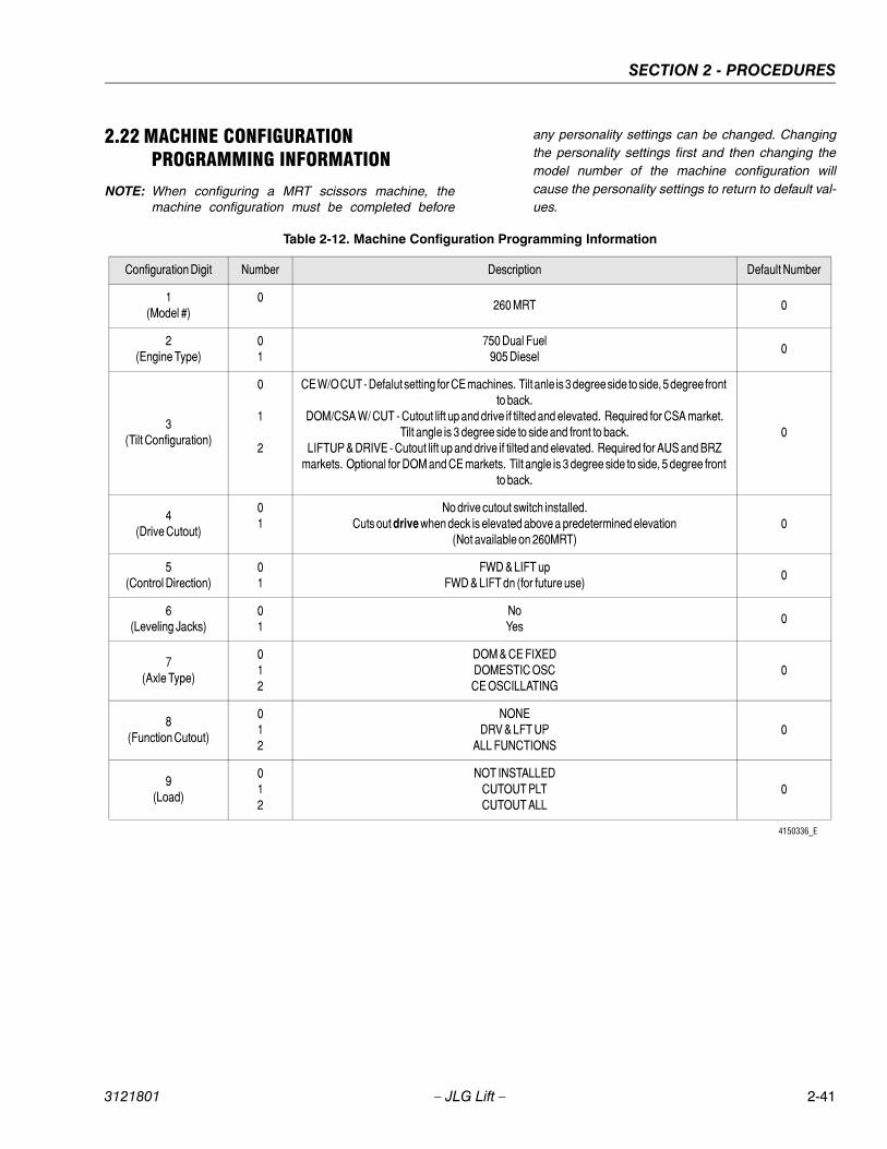
SECTION 2 - PROCEDURES
2.22 MACHINE CONFIGURATION PROGRAMMING INFORMATION
NOTE: When configuring a MRT scissors machine, themachine configuration must be completed before
any personality settings can be changed. Changingthe personality settings first and then changing themodel number of the machine configuration willcause the personality settings to return to default val-ues.
Table 2-12. Machine Configuration Programming Information
Configuration Digit Number Description Default Number
1(Model #)
0260 MRT 0
2(Engine Type)
01
750 Dual Fuel905 Diesel
0
3(Tilt Configuration)
0
1
2
CE W/O CUT - Defalut setting for CE machines. Tilt anle is 3 degree side to side, 5 degree front to back.
DOM/CSA W/ CUT - Cutout lift up and drive if tilted and elevated. Required for CSA market. Tilt angle is 3 degree side to side and front to back.
LIFTUP & DRIVE - Cutout lift up and drive if tilted and elevated. Required for AUS and BRZ markets. Optional for DOM and CE markets. Tilt angle is 3 degree side to side, 5 degree front
to back.
0
4(Drive Cutout)
01
No drive cutout switch installed.Cuts out drive when deck is elevated above a predetermined elevation
(Not available on 260MRT)0
5(Control Direction)
01
FWD & LIFT upFWD & LIFT dn (for future use)
0
6(Leveling Jacks)
01
NoYes
0
7(Axle Type)
012
DOM & CE FIXEDDOMESTIC OSCCE OSCILLATING
0
8(Function Cutout)
012
NONEDRV & LFT UP
ALL FUNCTIONS0
9(Load)
012
NOT INSTALLEDCUTOUT PLTCUTOUT ALL
0
4150336_E
3121801 – JLG Lift – 2-41
SECTION 2 - PROCEDURES
2.23 PREVENTIVE MAINTENANCE AND INSPECTION SCHEDULE
The preventive maintenance and inspection checks arelisted and defined in the following table. This table isdivided into two basic parts, the “AREA” to be inspectedand the “INTERVAL” at which the inspection is to takeplace. Under the “AREA” portion of the table, the varioussystems along with the components that make up thatsystem are listed. The “INTERVAL” portion of the table isdivided into five columns representing the various inspec-tion time periods. The numbers listed within the intervalcolumn represent the applicable inspection code forwhich that component is to be checked.
The checks and services listed in this schedule are notintended to replace any local or regional regulations thatmay pertain to this type of equipment nor should the listsbe considered as all inclusive. Variances in interval timesmay occur due to climate and/or conditions and depend-ing on the location and use of the machine.
JLG Industries requires that a complete annual inspectionbe performed in accordance with the “Annual MachineInspection Report” form. Forms are supplied with eachnew machine and are also available from JLG CustomerService. Form must be completed and returned to JLGIndustries.
JLG INDUSTRIES REQUIRES THAT A COMPLETE ANNUALINSPECTION BE PERFORMED IN ACCORDANCE WITH THE“ANNUAL MACHINE INSPECTION REPORT” FORM.
NOTE: This machine requires periodic safety and mainte-nance inspections be a JLG Dealer. A decal locatedon the frame affords a place to record (stamp)inspection dates. Notify dealer if inspection is over-due.
The inspection and maintenance code numbers are as fol-lows:
1. Check for proper and secure installation.
2. Check for visible damage and legibility.
3. Check for proper fluid level.
4. Check for any structural damage; cracked or brokenwelds; bent or warped surfaces.
5. Check for leakage.
6. Check for presence of excessive dirt or foreignmaterial.
7. Check for proper operation and freedom of move-ment.
8. Check for excessive wear or damage.
9. Check for proper tightness and adjustment.
10. Drain, clean and refill.
11. Check for proper operation while pump/motor isrunning.
12. Check for proper lubrication.
13. Check for evidence of scratches, nicks or rust andfor straightness of rod.
14. Check for condition of element; replace as neces-sary.
15. Check for proper inflation.
16. Check Inspection Decal for current inspectionstamp.
2-42 – JLG Lift – 3121801

SECTION 2 - PROCEDURES
Table 2-13. Preventive Maintenance and Safety Inspection
AREA INTERVAL
10Hours(Daily)
50 Hours(Weekly)
200 Hours(Monthly)
500 Hours(3 Month)
1000 Hours(6 Month)
PLATFORM
1. Controller 1,11
2. Switches 1,11
3. Placards and Decals 1,2
4. Control Tags 1,2
5. Hoses and Cables 4,8
6. Wear Pads 8
7. Handrails and Chains 1,4
CHASSIS
1. Engine Oil 3 5
2. Battery 3 5
3. Air Cleaner 1 14
4. Exhaust System 1 1,5
5. Engine Mounts 1
6. Hydraulic Pump 1 5
7. Valves 1 5
8. Hydraulic Filter (See Lubrication Chart) 5,14 14
9. Hydraulic Hoses and Tubing 1 5
10. Hydraulic Oil Tank* 3 5 4
11. Hydraulic Tank Breather 6,14
12. Fuel Tank 3,5 4
13. Lift Cylinder 1,12 5,6,13 4
14. Limit Switch 1,7
15. Tilt Alarm Switch 1,7
16. Placards and Decals 1,2
17. Wheel and Tire Assemblies 1 8,9
18. Drive Motors 1,5,6
19. Drive Brakes 1,6 8
20. Drive Torque Hubs 1,3,5,6
21. Steer Cylinder 1 5,6,13 4
22. Steer Components 1 4,6 8
23. Wheel Bearings (2 Wheel Drive) 8 12
24. Sizzor Arms 1,4
25. Safety Props 1,4
26. Sliding Wear Pads 8
27. Pivot Pins/Bolts 1,4 7,8
28. Switches, Ground Control 1,11
29. Control Tags 1,2
* Inspection and Maintenance code 10 to be performed annually
3121801 – JLG Lift – 2-43

SECTION 2 - PROCEDURES
NOTES:
2-44 – JLG Lift – 3121801

SECTION 3 - GENERAL ELECTRICAL INFORMATION & SCHEMATICS
SECTION 3. GENERAL ELECTRICAL INFORMATION & SCHEMATICS
3.1 GENERAL
This section contains schematics to be used for locating and correcting most of the operating problems which may develop.If a problem should develop which is not presented in this section or which is not corrected by listed corrective actions, tech-nically qualified guidance should be obtained before proceeding with any maintenance.
3.2 MULTIMETER BASICS
A wide variety of multimeters or Volt Ohm Meters (VOM) can be used for troubleshooting your equipment. A digital meterwith reasonable accuracy (within 7%) is recommended for the measurements in these procedures. This section shows dia-grams of a common, digital VOM configured for several different circuit measurements. Instructions for your VOM may vary.Please consult the meter operator’s manual for more information.
Grounding
"Grounding the meter" means to take the black lead (which is connected to the COM (common) or negative port) and touchit to a good path to the negative side of the voltage source.
Backprobing
To "backprobe" means to take the measurement by accessing a connector’s contact on the same side as the wires, the backof the connector. Readings can be done while maintaining circuit continuity this way. If the connector is the sealed type,great care must be taken to avoid damaging the seal around the wire. It is best to use probes or probe tips specificallydesigned for this technique, especially on sealed connectors. Whenever possible insert probes into the side of the connec-tor such that the test also checks both terminals of the connection. It is possible to inspect a connection within a closed con-nector by backprobing both sides of a connector terminal and measuring resistance. Do this after giving each wire a gentlepull to ensure the wires are still attached to the contact and contacts are seated in the connector.
Min/Max
Use of the "Min/Max" recording feature of some meters can help when taking measurements of intermittent conditions whilealone. For example, you can read the voltage applied to a solenoid when it is only operational while a switch, far from thesolenoid and meter, is held down.
Polarity
Finding a negative voltage or current reading when expecting a positive reading frequently means the leads are reversed.Check what reading is expected, the location of the signal and that the leads are connected to the device under test cor-rectly. Also check that the lead on the "COM" port goes to the ground or negative side of the signal and the lead on the otherport goes to the positive side of the signal.
Scale
M = Mega = 1,000,000 * (Displayed Number)
k = kilo = 1,000 * (Displayed Number)
m = milli = (Displayed Number) / 1,000
μ = micro = (Displayed Number) / 1,000,000
Example: 1.2 kΩ = 1200 Ω
Example: 50 mA = 0.05 A
3121801 – JLG Lift – 3-1

SECTION 3 - GENERAL ELECTRICAL INFORMATION & SCHEMATICS
Voltage Measurement Resistance Measurement
Figure 3-1. Voltage Measurement (DC) Figure 3-2. Resistance Measurement
• If meter is not auto ranging, set it to the correct range(See multimeter’s operation manual)
• Use firm contact with meter leads
• First test meter and leads by touching leads together.Resistance should read a short circuit (very low resis-tance)
• Circuit power must be turned OFF before testingresistance
• Disconnect component from circuit before testing
• If meter is not auto ranging, set it to the correct range(See multimeter’s operation manual)
• Use firm contact with meter leads
3-2 – JLG Lift – 3121801

SECTION 3 - GENERAL ELECTRICAL INFORMATION & SCHEMATICS
Continuity Measurement Current Measurement
Figure 3-3. Continuity Measurement Figure 3-4. Current Measurement (DC)
• Some meters require a separate button press toenable audible continuity testing
• Circuit power must be turned OFF before testing con-tinuity
• Disconnect component from circuit before testing
• Use firm contact with meter leads
• First test meter and leads by touching leads together.Meter should produce an audible alarm, indicatingcontinuity
• Set up the meter for the expected current range
• Be sure to connect the meter leads to the correctjacks for the current range you have selected
• If meter is not auto ranging, set it to the correct range(See multi meter’s operation manual)
• Use firm contact with meter leads
3121801 – JLG Lift – 3-3
SECTION 3 - GENERAL ELECTRICAL INFORMATION & SCHEMATICS
Continuity Measurement Over Long DistancesWhen trying to determine continuity of a harness or wire, longer than the reach of standard instrument leads, is possible toperform the check without excessively long leads. Using the other wires in the harness one can determine the condition of aparticular wire in the harness.
Requirements:• Harness with at least three separate wires including the wire under test.
• These wires must be able to be isolated from other wires, etc.
• Jumper or method to connect contacts on one side of harness.
• Meter that can measure resistance or continuity.
ProcedureTest multimeter leads resistance. Subtract this value from the measured resistance of the wires to get a more accurate mea-surement.
Consult the circuit schematic to determine which wires to use in addition to wire under test, here called wire #1 and wire #2,and how to isolate these wires. These wires should appear in the same connectors as the wire under test or are within reachof the jumper.
1. Disconnect all connections associated with the wire under test and the two additional wires. If harness is not com-pletely isolated disconnect battery terminals also, as a precaution.
2. Measure continuity between all three wires, the wire under test, wire #1 and wire #2. These should be open. If not,repair the shorted wires or replace the harness.
3. On one side, jumper from contact of wire #1 and wire #2.
4. Measure continuity between wire #1 and wire #2. If there is continuity, both wires are good and can be used for thistest. If there is not continuity, either wire could be bad. Check connections and measurement setup. Redo measure-ment. If still no continuity, repair wires or consult schematic for other wires to use for test.
5. Jumper from wire under test to wire #1.
6. Measure continuity. If there is continuity, the wire under test is good. Resistance of a wire increases as the lengthincreases and as the diameter decreases.
One can find the continuity of two wires, here #1 and #2, at once by following steps 1 through 4. If there is a problem thethird wire is used to troubleshoot the other wires. To find the problem, start at step 1 and use the entire procedure.
3-4 – JLG Lift – 3121801
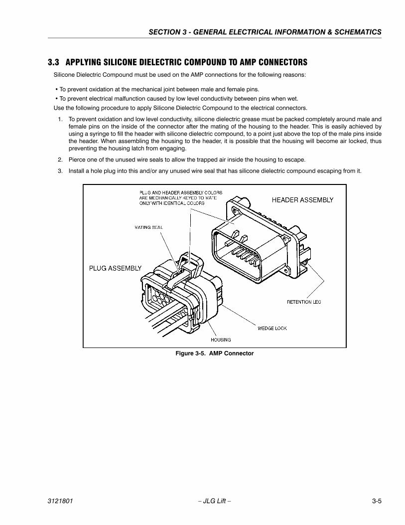
SECTION 3 - GENERAL ELECTRICAL INFORMATION & SCHEMATICS
3.3 APPLYING SILICONE DIELECTRIC COMPOUND TO AMP CONNECTORSSilicone Dielectric Compound must be used on the AMP connections for the following reasons:
• To prevent oxidation at the mechanical joint between male and female pins.
• To prevent electrical malfunction caused by low level conductivity between pins when wet.
Use the following procedure to apply Silicone Dielectric Compound to the electrical connectors.
1. To prevent oxidation and low level conductivity, silicone dielectric grease must be packed completely around male andfemale pins on the inside of the connector after the mating of the housing to the header. This is easily achieved byusing a syringe to fill the header with silicone dielectric compound, to a point just above the top of the male pins insidethe header. When assembling the housing to the header, it is possible that the housing will become air locked, thuspreventing the housing latch from engaging.
2. Pierce one of the unused wire seals to allow the trapped air inside the housing to escape.
3. Install a hole plug into this and/or any unused wire seal that has silicone dielectric compound escaping from it.
Figure 3-5. AMP Connector
3121801 – JLG Lift – 3-5
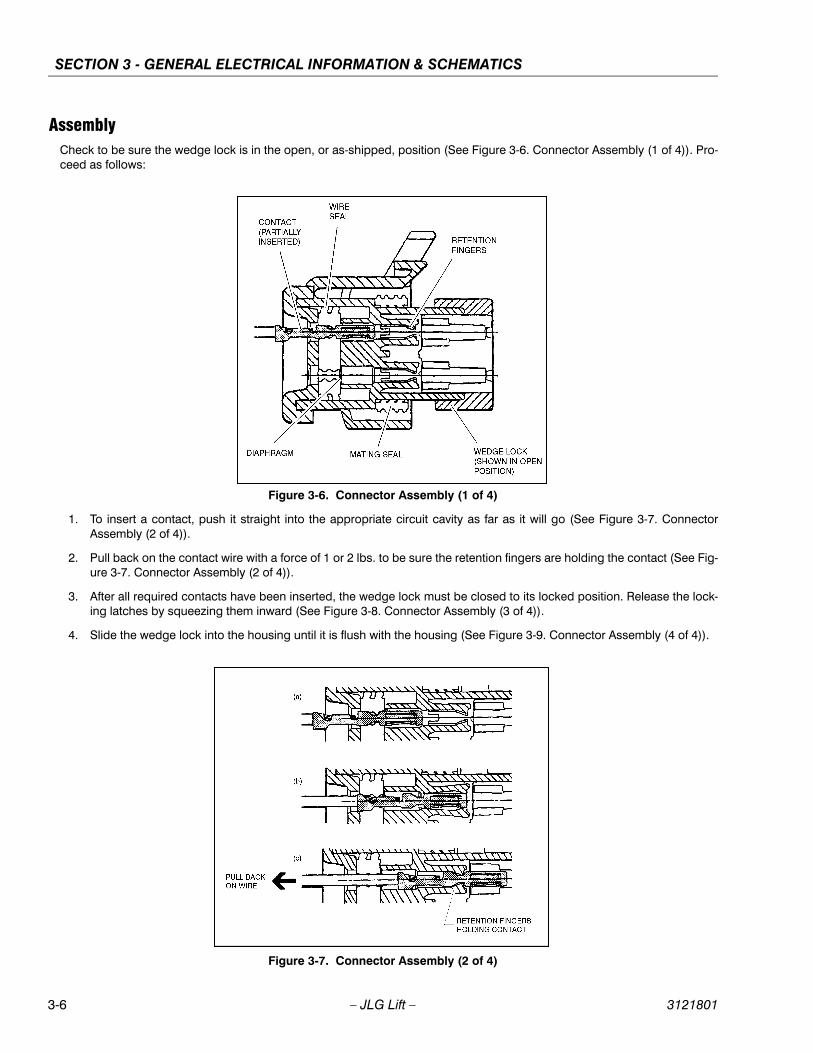
SECTION 3 - GENERAL ELECTRICAL INFORMATION & SCHEMATICS
AssemblyCheck to be sure the wedge lock is in the open, or as-shipped, position (See Figure 3-6. Connector Assembly (1 of 4)). Pro-ceed as follows:
Figure 3-6. Connector Assembly (1 of 4)
1. To insert a contact, push it straight into the appropriate circuit cavity as far as it will go (See Figure 3-7. ConnectorAssembly (2 of 4)).
2. Pull back on the contact wire with a force of 1 or 2 lbs. to be sure the retention fingers are holding the contact (See Fig-ure 3-7. Connector Assembly (2 of 4)).
3. After all required contacts have been inserted, the wedge lock must be closed to its locked position. Release the lock-ing latches by squeezing them inward (See Figure 3-8. Connector Assembly (3 of 4)).
4. Slide the wedge lock into the housing until it is flush with the housing (See Figure 3-9. Connector Assembly (4 of 4)).
Figure 3-7. Connector Assembly (2 of 4)
3-6 – JLG Lift – 3121801
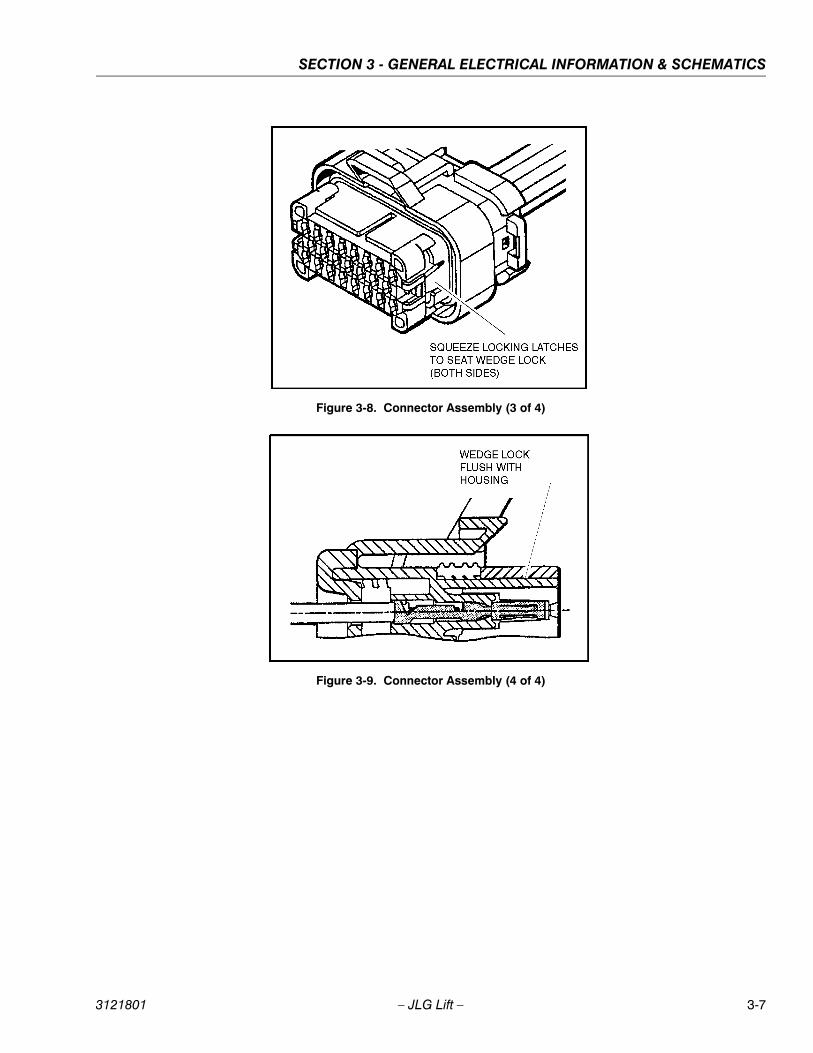
SECTION 3 - GENERAL ELECTRICAL INFORMATION & SCHEMATICS
Figure 3-8. Connector Assembly (3 of 4)
Figure 3-9. Connector Assembly (4 of 4)
3121801 – JLG Lift – 3-7
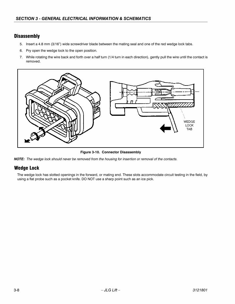
SECTION 3 - GENERAL ELECTRICAL INFORMATION & SCHEMATICS
Disassembly5. Insert a 4.8 mm (3/16”) wide screwdriver blade between the mating seal and one of the red wedge lock tabs.
6. Pry open the wedge lock to the open position.
7. While rotating the wire back and forth over a half turn (1/4 turn in each direction), gently pull the wire until the contact isremoved.
Figure 3-10. Connector Disassembly
NOTE: The wedge lock should never be removed from the housing for insertion or removal of the contacts.
Wedge LockThe wedge lock has slotted openings in the forward, or mating end. These slots accommodate circuit testing in the field, byusing a flat probe such as a pocket knife. DO NOT use a sharp point such as an ice pick.
3-8 – JLG Lift – 3121801
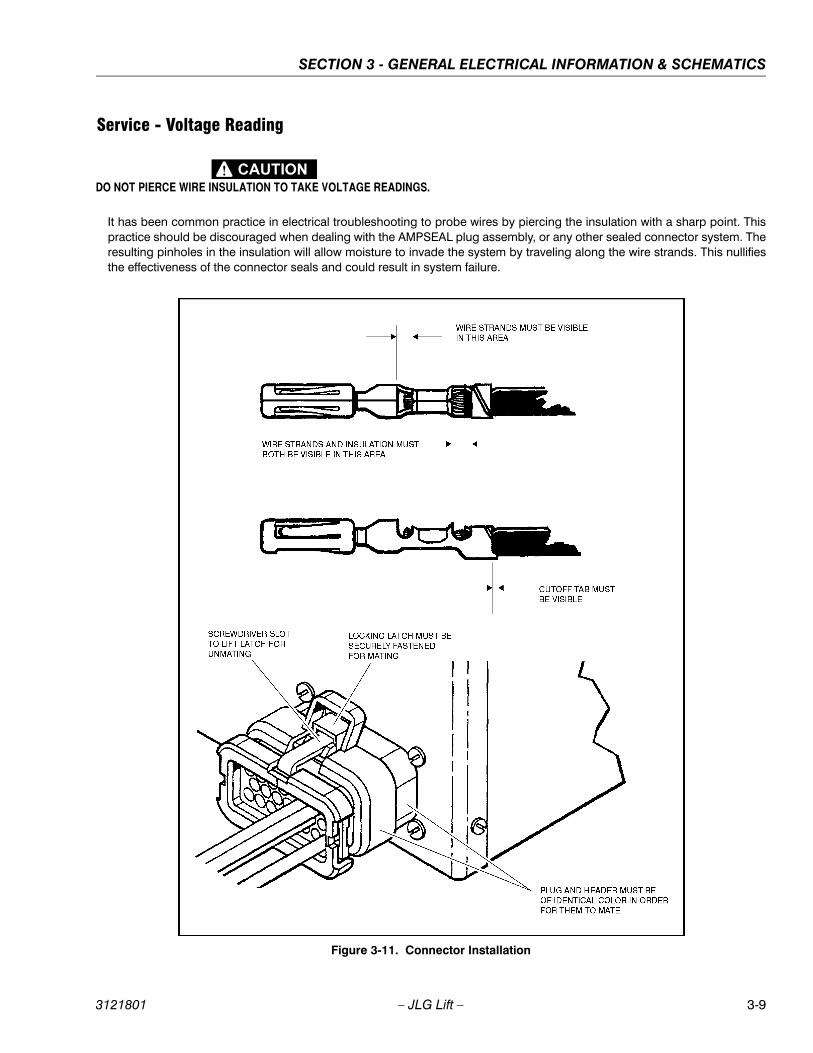
SECTION 3 - GENERAL ELECTRICAL INFORMATION & SCHEMATICS
Service - Voltage Reading
DO NOT PIERCE WIRE INSULATION TO TAKE VOLTAGE READINGS.
It has been common practice in electrical troubleshooting to probe wires by piercing the insulation with a sharp point. Thispractice should be discouraged when dealing with the AMPSEAL plug assembly, or any other sealed connector system. Theresulting pinholes in the insulation will allow moisture to invade the system by traveling along the wire strands. This nullifiesthe effectiveness of the connector seals and could result in system failure.
Figure 3-11. Connector Installation
3121801 – JLG Lift – 3-9
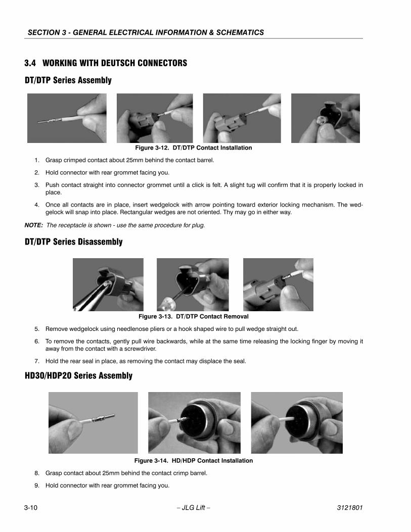
SECTION 3 - GENERAL ELECTRICAL INFORMATION & SCHEMATICS
3.4 WORKING WITH DEUTSCH CONNECTORS
DT/DTP Series Assembly
Figure 3-12. DT/DTP Contact Installation
1. Grasp crimped contact about 25mm behind the contact barrel.
2. Hold connector with rear grommet facing you.
3. Push contact straight into connector grommet until a click is felt. A slight tug will confirm that it is properly locked inplace.
4. Once all contacts are in place, insert wedgelock with arrow pointing toward exterior locking mechanism. The wed-gelock will snap into place. Rectangular wedges are not oriented. Thy may go in either way.
NOTE: The receptacle is shown - use the same procedure for plug.
DT/DTP Series Disassembly
Figure 3-13. DT/DTP Contact Removal
5. Remove wedgelock using needlenose pliers or a hook shaped wire to pull wedge straight out.
6. To remove the contacts, gently pull wire backwards, while at the same time releasing the locking finger by moving itaway from the contact with a screwdriver.
7. Hold the rear seal in place, as removing the contact may displace the seal.
HD30/HDP20 Series Assembly
Figure 3-14. HD/HDP Contact Installation
8. Grasp contact about 25mm behind the contact crimp barrel.
9. Hold connector with rear grommet facing you.
3-10 – JLG Lift – 3121801

SECTION 3 - GENERAL ELECTRICAL INFORMATION & SCHEMATICS
10. Push contact straight into connector grommet until a positive stop is felt. A slight tug will confirm that it is properlylocked in place.
Figure 3-15. HD/HDP Locking Contacts Into Position
NOTE: For unused wire cavities, insert sealing plugs for full environmental sealing
HD30/HDP20 Series Disassembly
Figure 3-16. HD/HDP Contact Removal
11. With rear insert toward you, snap appropriate size extractor tool over the wire of contact to be removed.
12. Slide tool along into the insert cavity until it engages contact and resistance is felt.
13. Pull contact-wire assembly out of connector.
Figure 3-17. HD/HDP Unlocking Contacts
NOTE: Do Not twist or insert tool at an angle.
3121801 – JLG Lift – 3-11

SECTION 3 - GENERAL ELECTRICAL INFORMATION & SCHEMATICS
3.5 SWITCHES
Basic checkThe following check determines if the switch is functioning properly, not the circuit in which the switch is placed. A switchis functioning properly when there is continuity between the correct terminals or contacts only when selected.
1. De-energize the circuit.
2. Isolate the switch from the rest of the circuit if possible. If not possible, keep in mind it may affect readings.
3. Access the terminals to the switch.
4. If the switch has two terminals:
a. Measure resistance across the terminals.
b. Change the switch position.
c. Measure resistance again with the leads in the same positions. If the meter was reading short, it should read anopen. If the meter was reading open it should read short.
5. If the switch has more than two terminals, consult the schematic or switch diagram to determine what terminals willbe connected. The test is similar to testing a switch with two terminals.
a. Place one meter lead on the common contact and the other on a different contact in the same circuit.
b. Cycle through all positions of the switch. The meter should read short only when the switch connects the twoterminals and open otherwise.
c. If the switch has more than one common contact repeat the process for that circuit.
Limit SwitchesLimit switches are used to control movement or indicate position. Mechanical limit switches are just like manually oper-ated switches except that the moving object operates the switch. These switches can be tested the same way as a stan-dard switch by manually operating the sensing arm.
Another type of limit switch used by JLG is the inductive proximity switch, also referred to as a "prox switch". Inductiveproximity switches are actuated only by ferrous metal (metal that contains Iron, such as steel) near the switch. They donot require contact, and must be energized to actuate. These types of switches can be used to detect boom or platformposition, for example. These switches have a sensing face where the switch can detect ferrous metal close to it. To findthe sensing face, take note how the switch is mounted and how the mechanisms meet the switch. Test this type of switchas follows:
1. Remove prox switch from its mount.
2. Reconnect harness if it was disconnected for step a, and turn on machine.
3. Hold switch away from metal and observe switch state in the control system diagnostics using the Analyzer. Seevehicle or control system documentation on how to do this.
4. Place sensing face of switch on the object to be sensed by the switch. If that is not available, use a piece of ferrousmetal physically similar to it. The switch state in the control system diagnostics should change.
5. When reinstalling or replacing switch be sure to follow mounting instructions and properly set the gap between theswitch and object sensed.
Automatic SwitchesIf the switch is actuated automatically, by temperature or pressure for example, find a way to manually actuate the switchto test it. Do this either by applying heat or pressure, for example, to the switch. These switches may need to be ener-gized to actuate.
1. Connect instrumentation to monitor and/or control the parameter the switch is measuring.
2. Observe switch state in control system with the Analyzer. See vehicle or control system documentation on how to dothis.
3-12 – JLG Lift – 3121801
SECTION 3 - GENERAL ELECTRICAL INFORMATION & SCHEMATICS
3. Operate system such that the switch actuates. This could be going over a certain pressure or temperature, for exam-ple. The state indicated in the control system should change.
Switch Wiring - Low Side, High Side
When controlling a load, a switch can be wired between the positive side of the power source and the load. This switch iscalled a "high side" switch. The switch supplies the power to the load. When a switch is wired between the negative sideof the power source and the load, it is a "low side" switch. The switch provides the ground to the load.
A low side switch will allow voltage to be present on the load. No power is applied because the switch is stopping currentflow. This voltage can be seen if the measurement is taken with one test lead on the load and the other on the batterynegative side or grounded to the vehicle. What is actually being measured is the voltage drop across the switch. Thiscould mislead a technician into thinking the load is receiving power but not operating. To produce an accurate picture ofpower or voltage applied to the load, measure voltage across the load’s power terminals. Also, the technician can mea-sure the voltage at both power terminals with respect to battery ground. The difference between those two measure-ments is the voltage applied to the load.
3.6 TROUBLESHOOTING
General
This section contains troubleshooting information to be used for locating and correcting most of the operating problemswhich may develop in the aerial platform. If a problem should develop which is not presented in this section or which is notcorrected by listed corrective actions, technically qualified guidance should be obtained before proceeding with any mainte-nance.
Troubleshooting Information
The troubleshooting procedures applicable to the aerial platform are listed and defined in following troubleshooting tables.
Each malfunction within an individual group or system is followed by a listing of probable causes which will enable determi-nation of the applicable remedial action. The probable causes and the remedial action should, where possible, be checkedin the order listed in the tables.
It should be noted that there is no substitute for a thorough knowledge of the equipment and related systems.
It should be recognized that the majority of the problems arising in the machine will be centered in the hydraulic and electri-cal systems. For this reason, every effort has been made to ensure that all likely problems in these areas are given the fullestpossible treatment. In the remaining machine groups, only those problems which are symptomatic of greater problemswhich have more than one probable cause and remedy are included. This means that problems for which the probablecause and remedy may be immediately obvious are not listed in this section.
The first rule for troubleshooting any circuit that is hydraulically operated and electrically controlled is to determine if the cir-cuit is lacking hydraulic oil and electrical control power. This can be ascertained by overriding the bypass valve (mechani-cally or electrically) so that oil is available to the function valve, then overriding the function valve mechanically. If the functionperforms satisfactorily, the problem exists with the control circuit.
Hydraulic Circuit Checks
The first reference for improper function of a hydraulic system, where the cause is not immediately apparent, should be theTroubleshooting Chart. The best place to begin the problem analysis is at the power source (pump). Once it is determinedthat the pump is serviceable, then a systematic check of the circuit components, beginning with the control, would follow.For aid in troubleshooting, refer to the Illustrated Parts Manual for hydraulic diagrams of the various circuits
3121801 – JLG Lift – 3-13

SECTION 3 - GENERAL ELECTRICAL INFORMATION & SCHEMATICS
.
Table 3-1. Elevation System Troubleshooting
TROUBLE PROBABLE CAUSE REMEDY
Platform Elevation System
No Response to LIft Control
Lift not performed within three seconds after lift function switch is selected.
Reselect lift function switch, then activate joystick within three seconds.
Enable circuit not functioning properly. Replace enable circuit card.
Lift control switch inoperative. Repair or replace control switch.
Hydraulic system oil low. Replenish oil as necessary.
Restricted or broken supply line on valve bank or pump.
Clean, repair or replace line.
Control valve not functioning properly. Repair or replace valve.
Lift cylinder not functioning properly. Repair or replace cylinder.
Hydraulic pump not functioning properly. Repair or replace pump.
Platform will not raise.
Joystick not activated within three sec-onds after lift switch is activated.
Activate lift switch, then activate joystick within three seconds.
Enable circuit not functioning properly. Replace enable circuit card.
Load capacity exceeded. (Personnel and/or equipment on platform).
Reduce load. (Refer to capacity placard).
Hydraulic system oil low. Replenish oil as necessary.
Restricted or broken hydraulic line or fit-ting.
Clean, repair, or replace line or fitting.
Control valve not functioning properly. Repair or replace valve.
Lift cylinder not functioning properly. Repair or replace lift cylinder.
Engine does not respond when lift control switch is moved to up position.
Refer to Electrical System Troubleshoot-ing - No response to control switch.
No electrical signal being sent to lift up control valve cartridge.
Refer to Electrical System Troubleshooting - No response to control switch.
Platform will not lower
Joystick not activated within three sec. after lift switch is activated.
Depress lift switch, then activate control-ler within three seconds.
Enable circuit not functioning properly. Replace enable circuit card.
No electrical signal sent to lift down con-trol valve cartridge.
Refer to Electrical System Troubleshoot- ing - No response to control switch.
Lift down control valve cartridge not functioning properly.
Repair or replace lift down control valve cartridge.
Lift cylinder not functioning properly. Repair or replace lift cylinder.
Engine does not respond when lift switch is moved to down position.
Refer to Electrical System Troubleshoot ing - No response to control switch.
No electrical signal being sent to lift down control valve.
Refer to Electrical System Troubleshoot ing - No response to control switch.
3-14 – JLG Lift – 3121801

SECTION 3 - GENERAL ELECTRICAL INFORMATION & SCHEMATICS
Platform raises and lowers erratically
Hydraulic system oil low. Replenish oil as necessary.
Restricted or broken hydraulic line or fit-ting.
Clean, repair or replace line.
Counterbalance valve on lift cyl. improp- rely adjusted or not functioning properly.
Replace valve.
Control valve not functioning properly. Repair or replace valve.
Worn seals in lift cylinder. Replace seals.
Lift cylinder not functioning properly. Repair or replace lift cylinder.
Platform drifts down
Manual lowering valve not functioning properly.
Repair or replace valve.
Worn seals in lift cylinder. Replace seals.
Holding valve on lift cylinder not function-ing properly.
Repair or replace valve.
High Drive does not operate below horizontal
Damaged wiring on limit switch. Repair or replace wiring.
Damaged limit switch. Replace limit switch
Table 3-1. Elevation System Troubleshooting
TROUBLE PROBABLE CAUSE REMEDY
3121801 – JLG Lift – 3-15

SECTION 3 - GENERAL ELECTRICAL INFORMATION & SCHEMATICS
Table 3-2. Chassis Troubleshooting
TROUBLE PROBABLE CAUSE REMEDY
Drive System
No response to drive controller
Joystick not activated within three sec-onds after drive select switch is activated.
Activate drive select switch, then activate joystick within three seconds.
Enable circuit not functioning properly. Replace enable circuit card.
Hydraulic system oil low. Replenish oil as necessary.
Hydraulic pump not functioning properly. Repair or replace pump.
Restricted or broken pump supply line. Clean, repair or replace line.
Drive motor not functioning properly. Repair or replace motor.
Damaged wiring on drive controller. Repair or replace wiring.
Drive controller not functioning properly. Repair or replace controller.
Drive brake not releasing. Determine cause and repair or replace brake.
Machine drives erratically
Microcircuit on controller improperly adjusted.
Adjust microswitch on controller for proper operation.
Machine will not travel forward
Joystick not activated within three sec-onds after drive switch is activated.
Activate drive switch, then activate joy-stick within three seconds.
Enable circuit not functioning properly. Replace enable circuit card.
Hydraulic system oil low. Replenish oil as necessary.
Restricted or broken hydraulic line or fit-ting.
Clean, repair or replace line or fitting.
Control valve not functioning properly. Repair or replace valve.
Drive motor not functioning properly. Repair or replace motor.
Brake not functioning properly. Repair or replace brake.
Engine will not respond when enable switch is activated and drive controller is activated.
Refer to Electrical System Troubleshoot-ing - No response to control switch.
No electrical signal being sent to the drive valve cartridge.
Refer to Electrical System Troubleshoot-ing - No response to control switch.
Machine will not travel in reverse
See: Machine will not travel forward.
3-16 – JLG Lift – 3121801
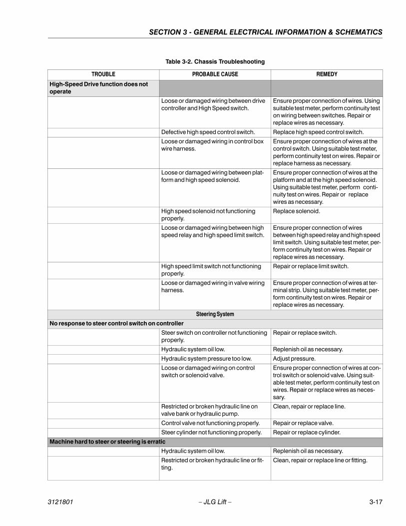
SECTION 3 - GENERAL ELECTRICAL INFORMATION & SCHEMATICS
High-Speed Drive function does not operate
Loose or damaged wiring between drive controller and High Speed switch.
Ensure proper connection of wires. Using suitable test meter, perform continuity test on wiring between switches. Repair or replace wires as necessary.
Defective high speed control switch. Replace high speed control switch.
Loose or damaged wiring in control box wire harness.
Ensure proper connection of wires at the control switch. Using suitable test meter, perform continuity test on wires. Repair or replace harness as necessary.
Loose or damaged wiring between plat-form and high speed solenoid.
Ensure proper connection of wires at the platform and at the high speed solenoid. Using suitable test meter, perform conti-nuity test on wires. Repair or replace wires as necessary.
High speed solenoid not functioning properly.
Replace solenoid.
Loose or damaged wiring between high speed relay and high speed limit switch.
Ensure proper connection of wires between high speed relay and high speed limit switch. Using suitable test meter, per-form continuity test on wires. Repair or replace wires as necessary.
High speed limit switch not functioning properly.
Repair or replace limit switch.
Loose or damaged wiring in valve wiring harness.
Ensure proper connection of wires at ter-minal strip. Using suitable test meter, per-form continuity test on wires. Repair or replace wires as necessary.
Steering System
No response to steer control switch on controller
Steer switch on controller not functioning properly.
Repair or replace switch.
Hydraulic system oil low. Replenish oil as necessary.
Hydraulic system pressure too low. Adjust pressure.
Loose or damaged wiring on control switch or solenoid valve.
Ensure proper connection of wires at con-trol switch or solenoid valve. Using suit-able test meter, perform continuity test on wires. Repair or replace wires as neces-sary.
Restricted or broken hydraulic line on valve bank or hydraulic pump.
Clean, repair or replace line.
Control valve not functioning properly. Repair or replace valve.
Steer cylinder not functioning properly. Repair or replace cylinder.
Machine hard to steer or steering is erratic
Hydraulic system oil low. Replenish oil as necessary.
Restricted or broken hydraulic line or fit-ting.
Clean, repair or replace line or fitting.
Table 3-2. Chassis Troubleshooting
TROUBLE PROBABLE CAUSE REMEDY
3121801 – JLG Lift – 3-17
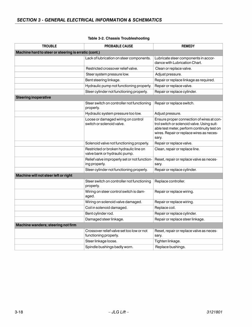
SECTION 3 - GENERAL ELECTRICAL INFORMATION & SCHEMATICS
Machine hard to steer or steering is erratic (cont.)
Lack of lubrication on steer components. Lubricate steer components in accor-dance with Lubrication Chart.
Restricted crossover relief valve. Clean or replace valve.
Steer system pressure low. Adjust pressure.
Bent steering linkage. Repair or replace linkage as required.
Hydraulic pump not functioning properly. Repair or replace valve.
Steer cylinder not functioning properly. Repair or replace cylinder.
Steering inoperative
Steer switch on controller not functioning properly.
Repair or replace switch.
Hydraulic system pressure too low. Adjust pressure.
Loose or damaged wiring on control switch or solenoid valve.
Ensure proper connection of wires at con-trol switch or solenoid valve. Using suit-able test meter, perform continuity test on wires. Repair or replace wires as neces-sary.
Solenoid valve not functioning properly. Repair or replace valve.
Restricted or broken hydraulic line on valve bank or hydraulic pump.
Clean, repair or replace line.
Relief valve improperly set or not function-ing properly.
Reset, repair or replace valve as neces-sary.
Steer cylinder not functioning properly. Repair or replace cylinder.
Machine will not steer left or right
Steer switch on controller not functioning properly.
Replace controller.
Wiring on steer control switch is dam-aged.
Repair or replace wiring.
Wiring on solenoid valve damaged. Repair or replace wiring.
Coil in solenoid damaged. Replace coil.
Bent cylinder rod. Repair or replace cylinder.
Damaged steer linkage. Repair or replace steer linkage.
Machine wanders; steering not firm
Crossover relief valve set too low or not functioning properly.
Reset, repair or replace valve as neces-sary.
Steer linkage loose. Tighten linkage.
Spindle bushings badly worn. Replace bushings.
Table 3-2. Chassis Troubleshooting
TROUBLE PROBABLE CAUSE REMEDY
3-18 – JLG Lift – 3121801
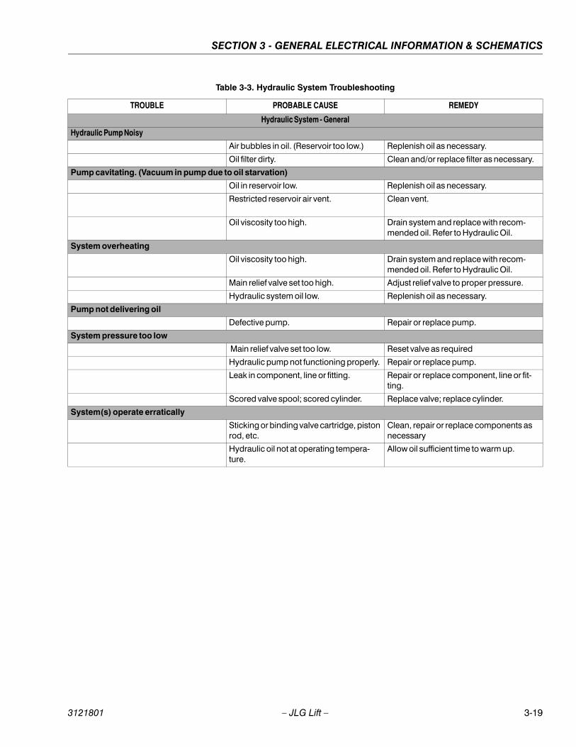
SECTION 3 - GENERAL ELECTRICAL INFORMATION & SCHEMATICS
Table 3-3. Hydraulic System Troubleshooting
TROUBLE PROBABLE CAUSE REMEDY
Hydraulic System - General
Hydraulic Pump Noisy
Air bubbles in oil. (Reservoir too low.) Replenish oil as necessary.
Oil filter dirty. Clean and/or replace filter as necessary.
Pump cavitating. (Vacuum in pump due to oil starvation)
Oil in reservoir low. Replenish oil as necessary.
Restricted reservoir air vent. Clean vent.
Oil viscosity too high. Drain system and replace with recom-mended oil. Refer to Hydraulic Oil.
System overheating
Oil viscosity too high. Drain system and replace with recom-mended oil. Refer to Hydraulic Oil.
Main relief valve set too high. Adjust relief valve to proper pressure.
Hydraulic system oil low. Replenish oil as necessary.
Pump not delivering oil
Defective pump. Repair or replace pump.
System pressure too low
Main relief valve set too low. Reset valve as required
Hydraulic pump not functioning properly. Repair or replace pump.
Leak in component, line or fitting. Repair or replace component, line or fit-ting.
Scored valve spool; scored cylinder. Replace valve; replace cylinder.
System(s) operate erratically
Sticking or binding valve cartridge, piston rod, etc.
Clean, repair or replace components as necessary
Hydraulic oil not at operating tempera-ture.
Allow oil sufficient time to warm up.
3121801 – JLG Lift – 3-19
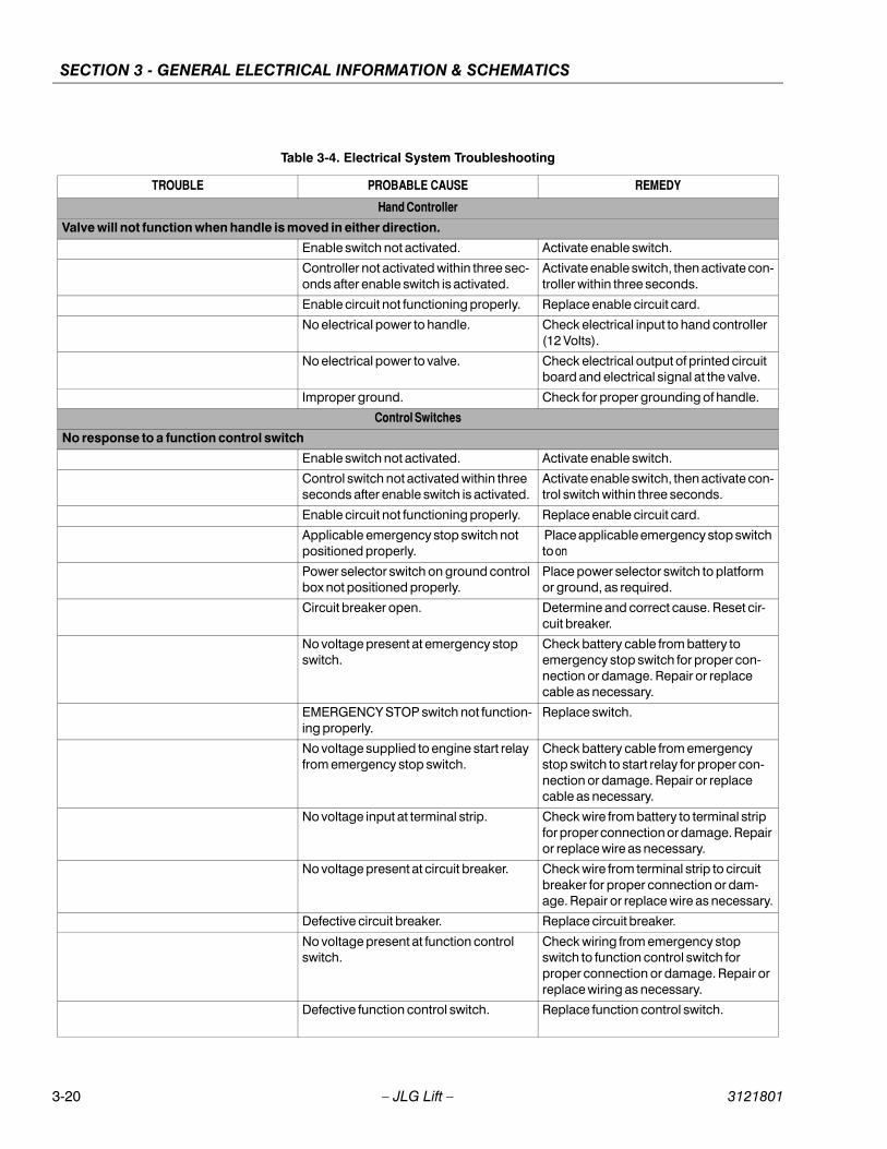
SECTION 3 - GENERAL ELECTRICAL INFORMATION & SCHEMATICS
Table 3-4. Electrical System Troubleshooting
TROUBLE PROBABLE CAUSE REMEDY
Hand Controller
Valve will not function when handle is moved in either direction.
Enable switch not activated. Activate enable switch.
Controller not activated within three sec-onds after enable switch is activated.
Activate enable switch, then activate con-troller within three seconds.
Enable circuit not functioning properly. Replace enable circuit card.
No electrical power to handle. Check electrical input to hand controller (12 Volts).
No electrical power to valve. Check electrical output of printed circuit board and electrical signal at the valve.
Improper ground. Check for proper grounding of handle.
Control Switches
No response to a function control switch
Enable switch not activated. Activate enable switch.
Control switch not activated within three seconds after enable switch is activated.
Activate enable switch, then activate con-trol switch within three seconds.
Enable circuit not functioning properly. Replace enable circuit card.
Applicable emergency stop switch not positioned properly.
Place applicable emergency stop switch to on
Power selector switch on ground control box not positioned properly.
Place power selector switch to platform or ground, as required.
Circuit breaker open. Determine and correct cause. Reset cir-cuit breaker.
No voltage present at emergency stop switch.
Check battery cable from battery to emergency stop switch for proper con-nection or damage. Repair or replace cable as necessary.
EMERGENCY STOP switch not function-ing properly.
Replace switch.
No voltage supplied to engine start relay from emergency stop switch.
Check battery cable from emergency stop switch to start relay for proper con-nection or damage. Repair or replace cable as necessary.
No voltage input at terminal strip. Check wire from battery to terminal strip for proper connection or damage. Repair or replace wire as necessary.
No voltage present at circuit breaker. Check wire from terminal strip to circuit breaker for proper connection or dam-age. Repair or replace wire as necessary.
Defective circuit breaker. Replace circuit breaker.
No voltage present at function control switch.
Check wiring from emergency stop switch to function control switch for proper connection or damage. Repair or replace wiring as necessary.
Defective function control switch. Replace function control switch.
3-20 – JLG Lift – 3121801
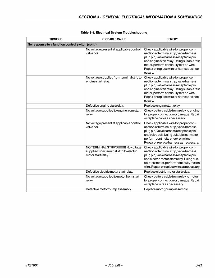
SECTION 3 - GENERAL ELECTRICAL INFORMATION & SCHEMATICS
No response to a function control switch (cont.)
No voltage present at applicable control valve coil.
Check applicable wire for proper con-nection at terminal strip, valve harness plug pin, valve harness receptacle pin and engine start relay. Using suitable test meter, perform continuity test on wire. Repair or replace wire or harness as nec-essary.
No voltage supplied from terminal strip to engine start relay.
Check applicable wire for proper con-nection at terminal strip, valve harness plug pin, valve harness receptacle pin and engine start relay. Using suitable test meter, perform continuity test on wire. Repair or replace wire or harness as nec-essary.
Defective engine start relay. Replace engine start relay.
No voltage supplied to engine from start relay.
Check battery cable from relay to engine for proper connection or damage. Repair or replace cable as necessary.
No voltage present at applicable control valve coil.
Check applicable wire for proper con-nection at terminal strip, valve harness plug pin, valve harness receptacle pin and valve coil. Using suitable test meter, perform continuity check on wires. Repair or replace harness as necessary.
NO TERMINAL STRIPS!!!!!!!! No voltage supplied from terminal strip to electric motor start relay.
Check applicable wire for proper con-nection at terminal strip, valve harness plug pin, valve harness receptacle pin and electric motor start relay. Using suit-able test meter, perform continuity test on wire. Repair or replace wire as necessary.
Defective electric motor start relay. Replace electric motor start relay.
No voltage supplied to motor from start relay.
Check battery cable from relay to motor for proper connection or damage. Repair or replace wire as necessary.
Defective motor/pump assembly. Replace motor/pump assembly.
Table 3-4. Electrical System Troubleshooting
TROUBLE PROBABLE CAUSE REMEDY
3121801 – JLG Lift – 3-21

SECTION 3 - GENERAL ELECTRICAL INFORMATION & SCHEMATICS
1001106560_B Sheet-1
Figure 3-18. Electrical Schematic - Sheet 1 of 3
3-22 – JLG Lift – 3121801
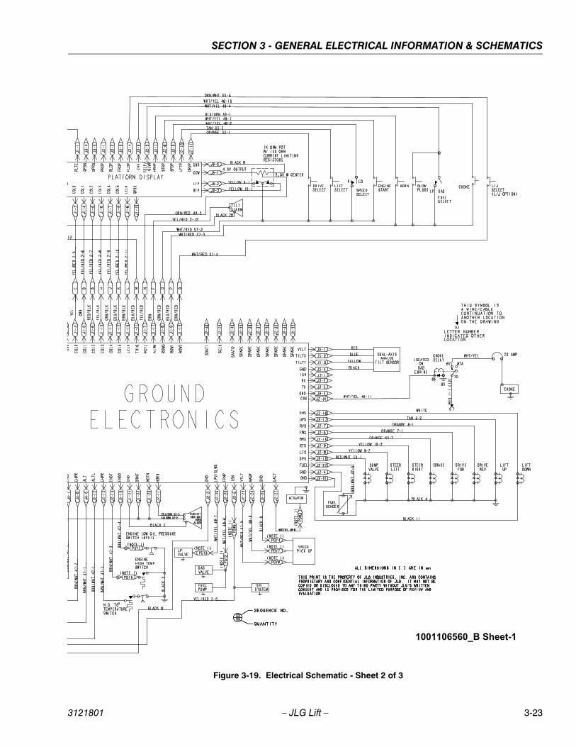
SECTION 3 - GENERAL ELECTRICAL INFORMATION & SCHEMATICS
1001106560_B Sheet-1
Figure 3-19. Electrical Schematic - Sheet 2 of 3
3121801 – JLG Lift – 3-23

SECTION 3 - GENERAL ELECTRICAL INFORMATION & SCHEMATICS
1001109660_B Sheet-2
Figure 3-20. Electrical Schematic - Sheet 3 of 3
3-24 – JLG Lift – 3121801

SECTION 3 - GENERAL ELECTRICAL INFORMATION & SCHEMATICS
NOTES:
3121801 – JLG Lift – 3-25
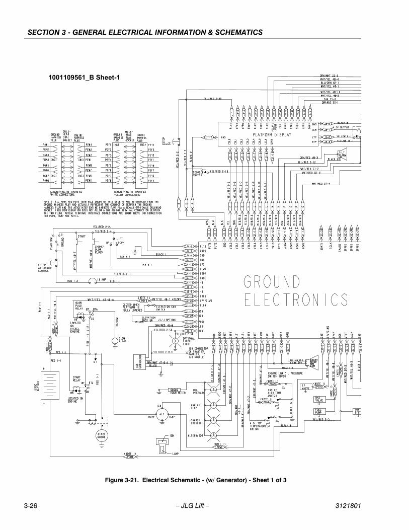
SECTION 3 - GENERAL ELECTRICAL INFORMATION & SCHEMATICS
1001109561_B Sheet-1
Figure 3-21. Electrical Schematic - (w/ Generator) - Sheet 1 of 3
3-26 – JLG Lift – 3121801
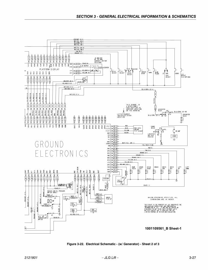
SECTION 3 - GENERAL ELECTRICAL INFORMATION & SCHEMATICS
1001109561_B Sheet-1
Figure 3-22. Electrical Schematic - (w/ Generator) - Sheet 2 of 3
3121801 – JLG Lift – 3-27

SECTION 3 - GENERAL ELECTRICAL INFORMATION & SCHEMATICS
1001109561_B Sheet-2
Figure 3-23. Electrical Schematic - (w/ Generator) - Sheet 3 of 3
3-28 – JLG Lift – 3121801

SECTION 3 - GENERAL ELECTRICAL INFORMATION & SCHEMATICS
NOTES:
3121801 – JLG Lift – 3-29
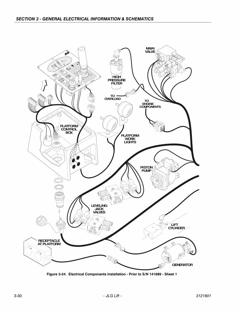
SECTION 3 - GENERAL ELECTRICAL INFORMATION & SCHEMATICS
MAINVALVE
HIGHPRESSURE
FILTER
PLATFORMWORKLIGHTS
PLATFORMCONTROL
BOX
PISTONPUMP
LIFTCYLINDER
GENERATOR
TOENGINE
COMPONENTS
TOOVERLOAD
LEVELINGJACK
VALVES
RECEPTACLE AT PLATFORM
Figure 3-24. Electrical Componants Installation - Prior to S/N 141689 - Sheet 1
3-30 – JLG Lift – 3121801
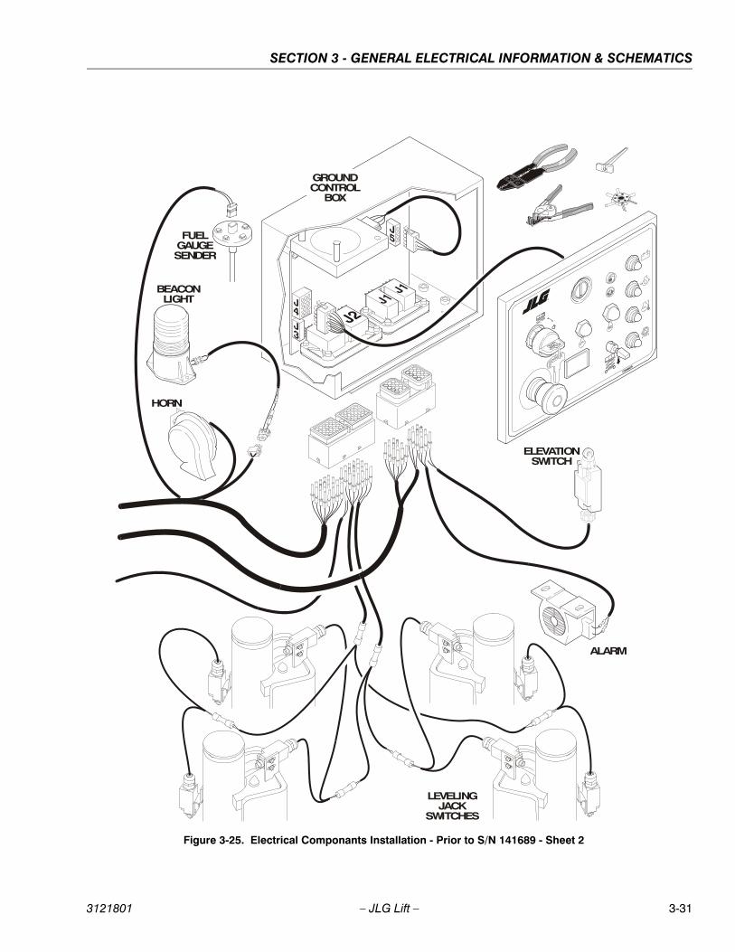
SECTION 3 - GENERAL ELECTRICAL INFORMATION & SCHEMATICS
BEACONLIGHT
ELEVATIONSWITCH
LEVELINGJACK
SWITCHES
HORN
FUELGAUGESENDER
GROUNDCONTROL
BOX
ALARM
Figure 3-25. Electrical Componants Installation - Prior to S/N 141689 - Sheet 2
3121801 – JLG Lift – 3-31
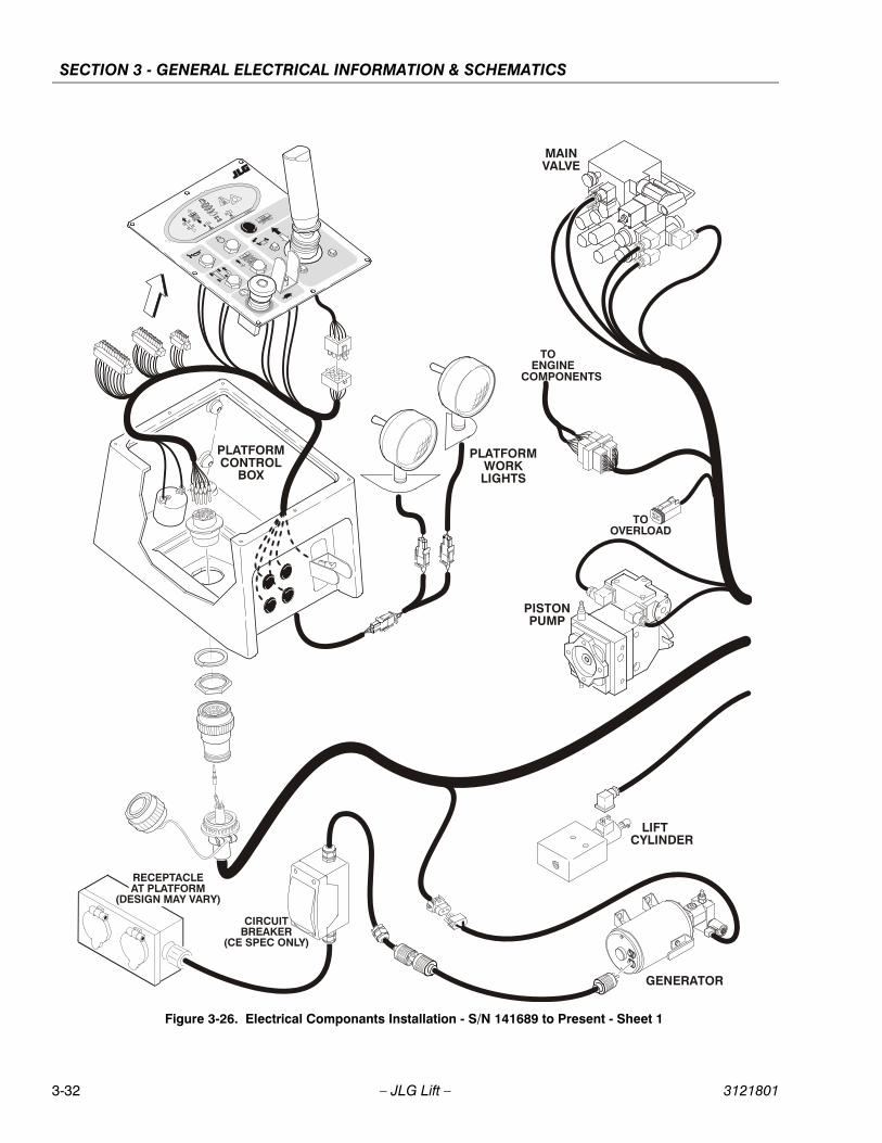
SECTION 3 - GENERAL ELECTRICAL INFORMATION & SCHEMATICS
MAINVALVE
PLATFORMWORKLIGHTS
PLATFORMCONTROL
BOX
PISTONPUMP
LIFTCYLINDER
GENERATOR
TOENGINE
COMPONENTS
TOOVERLOAD
RECEPTACLE AT PLATFORM
(DESIGN MAY VARY)
CIRCUITBREAKER
(CE SPEC ONLY)
Figure 3-26. Electrical Componants Installation - S/N 141689 to Present - Sheet 1
3-32 – JLG Lift – 3121801
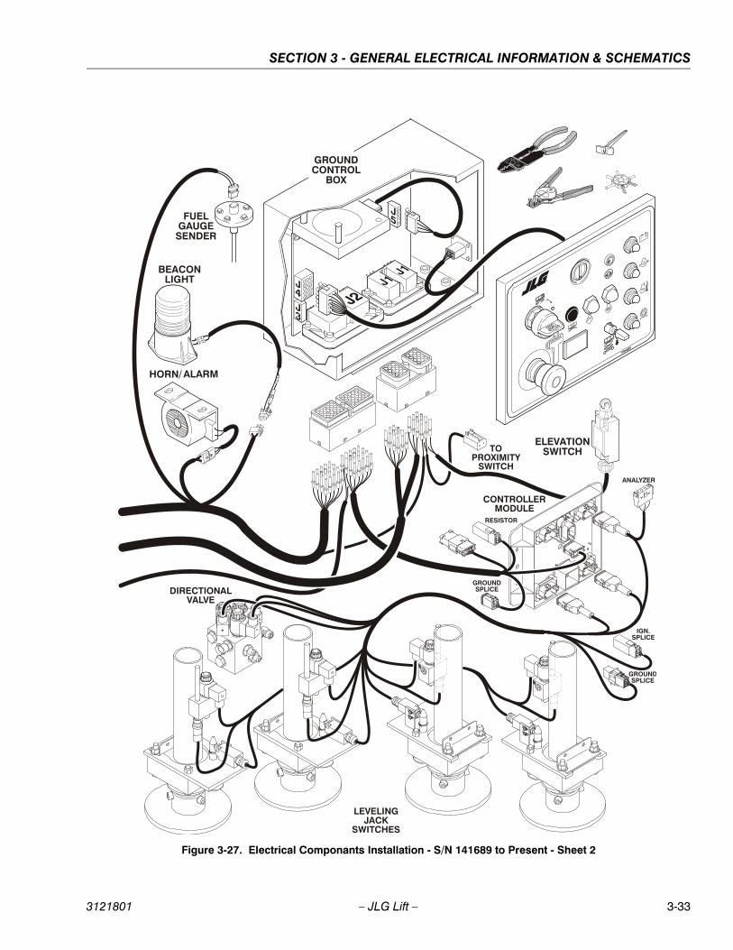
SECTION 3 - GENERAL ELECTRICAL INFORMATION & SCHEMATICS
GROUNDCONTROL
BOX
BEACONLIGHT
FUELGAUGE
SENDER
HORN/ ALARM
LEVELINGJACK
SWITCHES
CONTROLLERMODULE
IGN.SPLICE
GROUNDSPLICE
ELEVATIONSWITCH
GROUNDSPLICE
RESISTOR
DIRECTIONALVALVE
ANALYZER
TOPROXIMITY
SWITCH
Figure 3-27. Electrical Componants Installation - S/N 141689 to Present - Sheet 2
3121801 – JLG Lift – 3-33
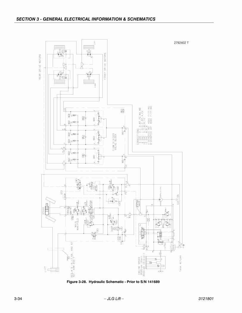
SECTION 3 - GENERAL ELECTRICAL INFORMATION & SCHEMATICS
2792402 T
Figure 3-28. Hydraulic Schematic - Prior to S/N 141689
3-34 – JLG Lift – 3121801

SECTION 3 - GENERAL ELECTRICAL INFORMATION & SCHEMATICS
2792717 D
Figure 3-29. Hydraulic Schematic - S/N 141689 to Present
3121801 – JLG Lift – 3-35
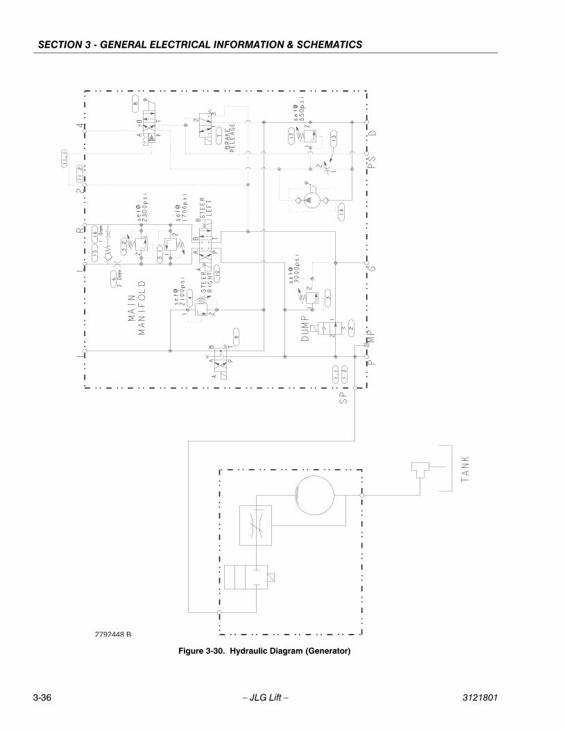
SECTION 3 - GENERAL ELECTRICAL INFORMATION & SCHEMATICS
2792448 B
Figure 3-30. Hydraulic Diagram (Generator)
3-36 – JLG Lift – 3121801
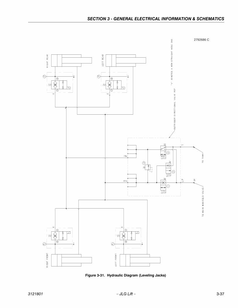
SECTION 3 - GENERAL ELECTRICAL INFORMATION & SCHEMATICS
2792686 C
Figure 3-31. Hydraulic Diagram (Leveling Jacks)
3121801 – JLG Lift – 3-37

SECTION 3 - GENERAL ELECTRICAL INFORMATION & SCHEMATICS
NOTES:
3-38 – JLG Lift – 3121801

Corporate OfficeJLG Industries, Inc.
1 JLG DriveMcConnellsburg PA. 17233-9533
USA (717) 485-5161 (717) 485-6417
JLG Worldwide LocationsJLG Industries (Australia)P.O. Box 511911 Bolwarra RoadPort MacquarieN.S.W. 2444Australia
+61 2 65 811111
+61 2 65 810122
JLG Latino Americana Ltda.Rua Eng. Carlos Stevenson,80-Suite 7113092-310 Campinas-SPBrazil
+55 19 3295 0407
+55 19 3295 1025
JLG Industries (UK) LtdBentley HouseBentley AvenueMiddletonGreater ManchesterM24 2GP - England
+44 (0)161 654 1000
+44 (0)161 654 1001
JLG France SASZ.I. de Baulieu47400 FauilletFrance
+33 (0)5 53 88 31 70
+33 (0)5 53 88 31 79
JLG Deutschland GmbHMax-Planck-Str. 21D - 27721 Ritterhude - IhlpohlGermany
+49 (0)421 69 350 20
+49 (0)421 69 350 45
JLG Equipment Services Ltd.Rm 1107 Landmark North39 Lung Sum AvenueSheung Shui N. T.Hong Kong
(852) 2639 5783
(852) 2639 5797
JLG Industries (Italia) s.r.l.Via Po. 2220010 Pregnana Milanese - MIItaly
+39 029 359 5210
+39 029 359 5845
Oshkosh - JLG Singapore T. E. P. Ltd.29 Tuas Ave 4Jurong Industrial Estate639379Singapore
+65-6591-9030
+65-6591-9031
Plataformas Elevadoras JLG Iberica, S.L.Trapadella, 2P.I. Castellbisbal Sur08755 Castellbisbal, BarcelonaSpain
+34 93 772 4700
+34 93 771 1762
JLG Sverige ABEnkopingsvagen 150Box 704SE - 176 27 JarfallaSweden
+46 (0)850 659 500
+46 (0)850 659 534
www.jlg.com
3121801
Top Related