


Languages
Pages
Legal

Self-Study Program 921603
All rights reserved. Technical specificationssubject to change withoutnotice.
Audi of America, Inc.3800 Hamlin RoadAuburn Hills, Michigan 48326
Audi 4.2-liter V8 FSI Engine
Service Training
Leading through Technology www.audiusa.com
Audi of America, Inc. Service Training Printed in U.S.A. Printed 07/2006 Course Number 921603
©2006 Audi of America, Inc.
All rights reserved. All information contained in this manual is based on the latest information available at the time of printing and is subject to the copyright and other intellectual property rights of Audi of America, Inc., its affiliated companies and its licensors. All rights are reserved to make changes at any time without notice. No part of this document may be reproduced, stored in a retrieval system, or transmitted in any form or by any means, electronic, mechanical, photocopying, recording or otherwise, nor may these materials be modified or reposted to other sites without the prior expressed written permission of the publisher.
All requests for permission to copy and redistribute information should be referred to Audi of America, Inc.
Always check Technical Bulletins and the latest electronic repair information for information that may supersede any information included in this booklet.
Trademarks: All brand names and product names used in this manual are trade names, service marks, trademarks, or registered trademarks; and are the property of their respective owners.
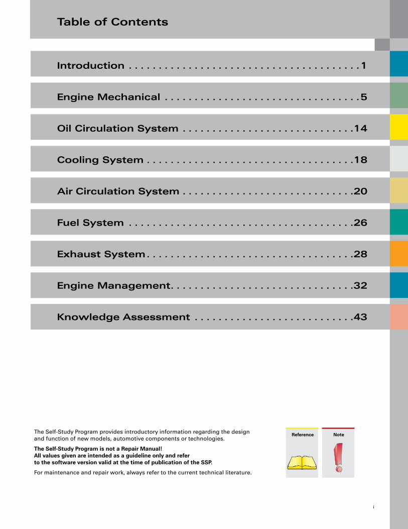
Table of Contents
i
The Self-Study Program provides introductory information regarding the design and function of new models, automotive components or technologies.
The Self-Study Program is not a Repair Manual! All values given are intended as a guideline only and refer to the software version valid at the time of publication of the SSP.
For maintenance and repair work, always refer to the current technical literature.
Reference Note
Introduction . . . . . . . . . . . . . . . . . . . . . . . . . . . . . . . . . . . . . . .1
Engine Mechanical . . . . . . . . . . . . . . . . . . . . . . . . . . . . . . . . .5
Oil Circulation System . . . . . . . . . . . . . . . . . . . . . . . . . . . . .14
Cooling System . . . . . . . . . . . . . . . . . . . . . . . . . . . . . . . . . . .18
Air Circulation System . . . . . . . . . . . . . . . . . . . . . . . . . . . . .20
Fuel System . . . . . . . . . . . . . . . . . . . . . . . . . . . . . . . . . . . . . .26
Exhaust System . . . . . . . . . . . . . . . . . . . . . . . . . . . . . . . . . . .28
Engine Management . . . . . . . . . . . . . . . . . . . . . . . . . . . . . . .32
Knowledge Assessment . . . . . . . . . . . . . . . . . . . . . . . . . . .43

ii
Introduction
1
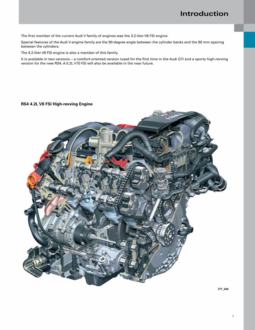
The first member of the current Audi V family of engines was the 3.2-liter V6 FSI engine.
Special features of the Audi V-engine family are the 90-degree angle between the cylinder banks and the 90 mm spacing between the cylinders.
The 4.2-liter V8 FSI engine is also a member of this family.
It is available in two versions – a comfort-oriented version (used for the first time in the Audi Q7) and a sporty high-revving version for the new RS4. A 5.2L V10 FSI will also be available in the near future.
RS4 4.2L V8 FSI High-revving Engine
377_045
Introduction
2
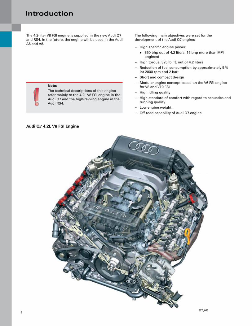
The 4.2-liter V8 FSI engine is supplied in the new Audi Q7 and RS4. In the future, the engine will be used in the Audi A6 and A8.
The following main objectives were set for the development of the Audi Q7 engine:
High specific engine power:
350 bhp out of 4.2 liters (15 bhp more than MPI engines)
High torque: 325 lb. ft. out of 4.2 liters
Reduction of fuel consumption by approximately 5 % (at 2000 rpm and 2 bar)
Short and compact design
Modular engine concept based on the V6 FSI engine for V8 and V10 FSI
High idling quality
High standard of comfort with regard to acoustics and running quality
Low engine weight
Off-road capability of Audi Q7 engine
–
●
–
–
–
–
–
–
–
–
Note:The technical descriptions of this engine refer mainly to the 4.2L V8 FSI engine in the Audi Q7 and the high-revving engine in the Audi RS4.
377_003
Audi Q7 4.2L V8 FSI Engine

Introduction
3
Technical Features
Fuel Straight Injection
Roller cam rocker arms with hydraulic lifters
Chain drives for camshafts and accessories
Variable camshaft adjustment for intake and exhaust camshafts
Two-stage magnesium variable inlet manifold with integrated tumble flap (not fitted in RS4)
Drive-by-wire throttle control
For compliance with exhaust emission standards LEV II
–
–
–
–
–
–
●
The main technical differences between the base engine and the high-revving engine lie in the following:
Crankshaft/connecting rods/pistons
Timing gear
Cylinder head
Oil supply
Engine cooling
Intake path
Exhaust system
Engine management
For an exact description of the differences, please refer to the relevant sections in this SSP.
–
–
–
–
–
–
–
–
377_002
RS4 4.2L V8 FSI Engine

Introduction
4
215
268
322
375
429
107
HP
lb ft
340
221
280
310
20000 5000 7000 9000
Torque/Power Curve
Maximum Torque in lb ft
V8 FSI Basic Engine in Audi Q7
V8 FSI High-revving Engine in RS4
Maximum Power Output in Horsepower (HP)
V8 FSI Basic Engine in Audi Q7
V8 FSI High-revving Engine in RS4
Engine Speed in RPM
Specifications
Audi Q7 RS4Engine Code BAR BNS
Type of Engine V8 90° V angle 4V FSI
Displacement in cm3 4163
Maximum Power Output in bhp 350 @ 6800 rpm 420 @ 7800 rpm
Maximum Torque in lbft 325 @ 3500 rpm 317 @5500 rpm
Valves per Cylinder 4
Bore in mm (in) 84.5 (3.33)
Stroke in mm (in) 92.8 (3.66)
Compression Ratio 12.5/-0.4 : 1
Firing Order 1–5–4–8–6–3–7–2
Engine Weight in lbs approximately 437* approximately 467**
Engine Management Bosch MED 9.1.1 Bosch 2x MED 9.1
Fuel Grade 98 / 95 RON (91 octane)
Exhaust Emission Standard LEV II
* with automatic transmission
** manual transmission including clutch and dual-mass flywheel

Engine Mechanical
5
Cylinder Block
The cylinder crankcase has a closed-deck design, which is stronger than the open-deck design.
In an open-deck cylinder block, the water jacket for cooling the cylinders is open at the top. The cylinder crankcase is made of a low-pressure gravity diecast aluminum-silicon alloy, is hypereutectic* and has a silicon content of 17 % (AlSi17Cu4Mg).
The cylinder crankcase underwent special heat treatment to increase its strength. The cylinder liners are mechanically stripped.
The cylinder crankcase of the high-revving engine was machined to higher specifications due to the higher stresses in this component. To minimize warping of the cylinder manifolds, the crankcase is honed under stress. For this purpose, a honing template is attached to the crankcase before the honing process in order to simulate the warping of the bolted-on cylinder manifold.
*Aluminum alloys are classed as hypoeutectic or hypereutectic, depending on their silicon content.
“Alusil” has a hypereutectic silicon content of 16 to 18 % so that primary silicon is precipitated on solidification of the molten metal.
A multistage honing process is applied. The silicon grains in the cylinder bores in the form of microscopically small, very hard particles are stripped to give the necessary wear resistance of the cylinder surfaces for the piston and piston rings.
Cylinder spacing: 90 mm
Cylinder bank offset: 18.5 mm
Overall engine length: 464 mm
Cylinder block height: 228 mm
–
–
–
–
The cylinder crankcase lower section (bedplate bearing cross-member) is made of aluminum with press-fitted iron main bearing covers made of grade 50 nodular cast iron. It is centered using centering pins, sealed with liquid sealant and bolted to the cylinder crankcase.
The main bearing is symmetric with the center of the main bearing, attached by four bolts. The bedplate type design provides high stability. The bedplate has the same stabilizing effect as a ladder frame.
Cylinder Block Top Section
Cylinder Block Bottom Section
Press-fit Main Bearings
Engine Mechanical
6
Crankshaft/Connecting Rods/Pistons
Crankshaft
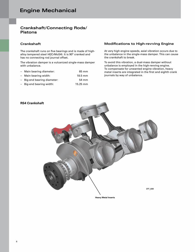
The crankshaft runs on five bearings and is made of high-alloy tempered steel (42CrMoS4). It is 90° cranked and has no connecting rod journal offset.
The vibration damper is a vulcanized single-mass damper with unbalance.
Main bearing diameter: 65 mm
Main bearing width: 18.5 mm
Big-end bearing diameter: 54 mm
Big-end bearing width: 15.25 mm
–
–
–
–
Modifications to High-revving Engine
At very high engine speeds, axial vibration occurs due to the unbalance in the single-mass damper. This can cause the crankshaft to break.
To avoid this vibration, a dual-mass damper without unbalance is employed in the high-revving engine. To compensate for unwanted engine vibration, heavy metal inserts are integrated in the first and eighth crank journals by way of unbalance.
Heavy Metal Inserts
377_035
RS4 Crankshaft
Engine Mechanical
7
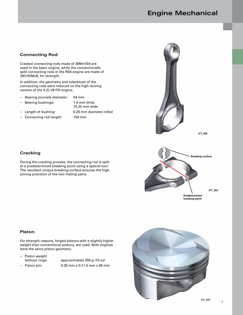
Connecting Rod
Cracked connecting rods made of 36MnVS4 are used in the basic engine, while the conventionally split connecting rods in the RS4 engine are made of 34CrNiMo8, for strength.
In addition, the geometry and tolerances of the connecting rods were reduced on the high revving version of the 4.2L V8 FSI engine.
Bearing journals diameter: 54 mm
Bearing bushings: 1.4 mm thick, 15.25 mm wide
Length of bushing: 0.20 mm diameter rolled
Connecting rod length: 154 mm
–
–
–
–
Cracking
During the cracking process, the connecting rod is split at a predetermined breaking point using a special tool. The resultant unique breaking surface ensures the high joining precision of the two mating parts.
Piston
For strength reasons, forged pistons with a slightly higher weight than conventional pistons, are used. Both engines have the same piston geometry.
Piston weight without rings: approximately 290 g (10 oz)
Piston pin: 0.20 mm x 0.11.5 mm x 40 mm
–
–
377_058
377_062
377_057
Breaking surface
Predetermined breaking point

Engine Mechanical
8
Crankcase Ventilation
The crankcase is ventilated through both cylinder heads.
The valve covers incorporate a large settling space. This space acts as a gravity-type oil separator. A fine oil separator is connected to the valve covers by means of plastic hoses.
A control piston, a bypass valve, a two-stage pressure limiting valve and an oil drain valve are integrated in the oil separator housing.
After the blow-by gas has passed through the fine oil separator, the gas flows into the intake manifold downstream of the throttle valve.
This inlet point is integrated in the coolant circulation system and heated. This prevents the crankcase breather from freezing up.
Note:Modifications after start of productionIn both engines, the separated oil flows into the crankcase through the cover in the inner V, adjacent the crankcase breather (no longer through the chain housing).
In the Audi Q7 engine, the crankcase is vented through a single chamber, i.e., via bank 2 only. Better icing protection is achieved in this way.
377_009
Breather Pipe Heater
Crankcase Breather System
Breather Pipe
Bypass Valve
Fine Oil Separator
Pressure Limiting Valve
Non-return Valve (crankcase breather)

Engine Mechanical
9
Fine Oil Separator
Blow-by gas volume is dependent on engine load and RPM. The fine oil (“oil spray”) is separated by means of a cyclone separator. Cyclone separators have a high separation efficiency over only a small volumetric range. For that reason, one, two, or three cyclones of the fine oil separator operate in parallel, depending on the gas-flow rate.
The cyclones are released by the control piston. The displacement of the control piston against its spring force is dependent on the gas-flow rate. Piston ring flutter at very high engine RPMs and low engine load can result in a very high gas-flow rate.
The crankcase internal pressure is set by the two-stage pressure control valve. The bypass valve, together with the control piston, ensures that the cyclones operate at the optimum operating point (if the volumetric flow rate is too high or too low, it will impair the functioning of the cyclones).
When the bypass valve opens, a fraction of the blow-by gas flows to the engine untreated, but the remainder is optimally treated by the cyclones.
The separated oil is collected in an oil reservoir beneath the cyclones. The oil cannot drain out of the reservoir until the oil drain valve is opened. The oil drain valve is closed as long as the pressure in the crankcase, i.e., below the valves, is higher than in the oil separator. The valve opens automatically due to gravity only at very low engine RPMs or when the engine is at a standstill, because the pressure conditions above and below the valve are in equilibrium.
The crankcase ventilation system also includes the crankcase breather. Air is extracted downstream of the air filter and flows through a non-return valve into the crankcase from above.
The non-return valve is located at the end of the vent line and is bolted between the two cylinder banks in the engine block.
A damping chamber is located below the non-return valve in the engine block. This prevents non-return valve flutter and eliminates noise.
A restrictor bore connects this chamber to the inner chamber of the crankcase. It has the task of supplying only a defined volume of fresh air to the crankcase.
377_011
Control Piston
Oil Reservoir
Triple Cyclones
Oil Drain Valve
Engine Mechanical
10
Chain Drives
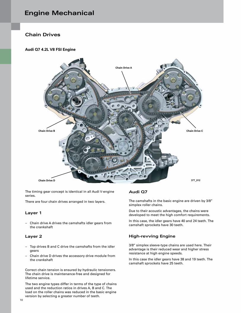
Audi Q7
The camshafts in the basic engine are driven by 3/8” simplex roller chains.
Due to their acoustic advantages, the chains were developed to meet the high comfort requirements.
In this case, the idler gears have 40 and 24 teeth. The camshaft sprockets have 30 teeth.
High-revving Engine
3/8“ simplex sleeve-type chains are used here. Their advantage is their reduced wear and higher stress resistance at high engine speeds.
In this case the idler gears have 38 and 19 teeth. The camshaft sprockets have 25 teeth.
The timing gear concept is identical in all Audi V-engine series.
There are four chain drives arranged in two layers.
Layer 1
Chain drive A drives the camshafts idler gears from the crankshaft
Layer 2
Top drives B and C drive the camshafts from the idler gears
Chain drive D drives the accessory drive module from the crankshaft
Correct chain tension is ensured by hydraulic tensioners. The chain drive is maintenance-free and designed for lifetime service.
The two engine types differ in terms of the type of chains used and the reduction ratios in drives A, B and C. The load on the roller chains was reduced in the basic engine version by selecting a greater number of teeth.
–
–
–
Audi Q7 4.2L V8 FSI Engine
377_012
Chain Drive A
Chain Drive B Chain Drive C
Chain Drive D

Engine Mechanical
11
Accessory Drive
The oil pump, water pump, power steering pump and the compressor are driven by chain drive D.
The chain is driven directly by the crankshaft, deflected by an idler gear and drives the chain sprocket seated on the gear module.
377_013
Air Conditioner Compressor
Coolant Pump
Power Steering Pump
Oil Pump
Gear Module
Engine Mechanical
12
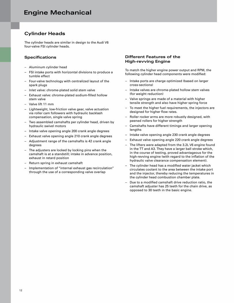
Cylinder Heads
The cylinder heads are similar in design to the Audi V6 four-valve FSI cylinder heads.
Specifications
Aluminum cylinder head
FSI intake ports with horizontal divisions to produce a tumble effect
Four-valve technology with centralized layout of the spark plugs
Inlet valve: chrome-plated solid stem valve
Exhaust valve: chrome-plated sodium-filled hollow stem valve
Valve lift 11 mm
Lightweight, low-friction valve gear, valve actuation via roller cam followers with hydraulic backlash compensation, single valve spring
Two assembled camshafts per cylinder head, driven by hydraulic swivel motors
Intake valve opening angle 200 crank angle degrees
Exhaust valve opening angle 210 crank angle degrees
Adjustment range of the camshafts is 42 crank angle degrees
The adjusters are locked by locking pins when the camshaft is at a standstill; intake in advance position, exhaust in retard position
Return spring in exhaust camshaft
Implementation of “internal exhaust gas recirculation” through the use of a corresponding valve overlap
–
–
–
–
–
–
–
–
–
–
–
–
–
–
Different Features of the High-revving Engine
To match the higher engine power output and RPM, the following cylinder head components were modified:
Intake ports are charge optimized (based on larger cross-sections)
Intake valves are chrome-plated hollow stem valves (for weight reduction)
Valve springs are made of a material with higher tensile strength and also have higher spring force
To meet the higher fuel requirements, the injectors are designed for higher flow rates.
Roller rocker arms are more robustly designed, with peened rollers for higher strength
Camshafts have different timings and larger opening lengths
Intake valve opening angle 230 crank angle degrees
Exhaust valve opening angle 220 crank angle degrees
The lifters were adapted from the 3.2L V6 engine found in the TT and A3. They have a larger ball stroke which, in the course of testing, proved advantageous for the high-revving engine (with regard to the inflation of the hydraulic valve clearance compensation element).
The cylinder head has a modified water jacket which circulates coolant to the area between the intake port and the injector, thereby reducing the temperatures in the cylinder head combustion chamber plate.
Due to a modified camshaft drive reduction ratio, the camshaft adjuster has 25 teeth for the chain drive, as opposed to 30 teeth in the basic engine.
–
–
–
–
–
–
–
–
–
–
–

Engine Mechanical
13
377_015
377_080
Crankcase BreatherValve Cover
Hall Sensor
High-pressure Fuel Pump with Fuel Metering Valve
Camshaft Assemblies
Intake Camshaft Adjuster
Exhaust Camshaft Adjuster with Return Spring

Oil Circulation System
14
Design
The oil supply in the basic engine, and likewise in the high-revving engine, is based on a traditional wet sump concept.
The focal point of development was on significant reduction of the oil flow rate. As a result, the oil remains in the sump longer and is better able to de-aerate.
The oil flow rate of 50 liters per minute (at 7000 rpm and 120°C oil temperature) is very low for an eight-cylinder engine. This has helped to minimize oil pump drive power and thus improve fuel economy.
The baffle plate is designed such that it not only prevents the crankshaft from churning the oil in the sump, but also strengthens the main bearing walls. In the basic engine, the oil is cooled by an oil-water heat exchanger.
In the more highly stressed high-revving engine, an additional oil-air heat exchanger is used to minimize the oil temperature even at high engine load. This additional heat exchanger is operated in parallel with the heat exchanger via a thermostat.
377_028
Oil Pressure Regulator
Components Exclusive to the Audi RS4
Oil Cooler (air)
Thermostat
Oil Cooler (coolant)
Oil Pump (gear)
Hydraulic Camshaft Adjustment
Cylinder Bank 1
Chain Tensioner Oil Filter Module
Cylinder Bank 2

Oil Circulation System
15
Oil Pump
The oil pump is located above the oil pan. The oil is drawn in through the filter in the bottom of the sump and simultaneously through the engine return duct while driving. All engine lubrication points are swept from the pressurized oil side.
Oil Filter Module
The oil filter module is designed as a full-flow filter. For easy maintenance, it is located in the inner V of the engine. The filter element can be easily replaced without the need for special tools. It is made of a polymer-based nonwoven material.
377_039
Pressurized Oil Side
Bottom Filter on Intake Side
Return Line from the Engine
377_040
Oil Filter Cap
Polymer-based Nonwoven Filter Element
To the Engine Circuit
From the Pressure Side of the Oil Pump

Oil Circulation System
16
Audi RS4 Sump
A reliable supply of oil in all driving situations is critical, especially in a sports car such as the RS4. The oil supply system in the high-revving engine was designed for racing applications in which it is subjected to lateral acceleration of up to 1.4 g. To ensure this, the sump in the RS4 has an additional system of flaps.
Design
Four flaps, whose axis of rotation is parallel to the longitudinal axis of vehicle, are arranged inside a housing. Each of the flaps opens toward the inside of the intake end of the oil pump.
Function
When the vehicle is cornering, the oil flows inside the sump toward the outside of the corner. The two flaps facing the outside of the corner close and hold the oil in the sump intake.
At the same time, the two flaps facing the inside of the corner open to allow additional oil to flow into the intake. This ensures a sufficient supply of oil to the oil pump.
377_037
A
Direction of Travel
377_038
To Outside of Corner Acting Centrifugal Forces
Flap Closes (oil back-pressure is increased)
Flap Opens (oil flows into intermediate chamber)
Cutaway View A
Oil Circulation System
17
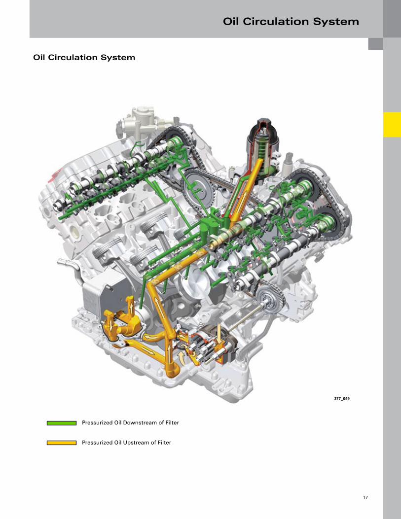
Oil Circulation System
377_059
Pressurized Oil Downstream of Filter
Pressurized Oil Upstream of Filter
Cooling System
18
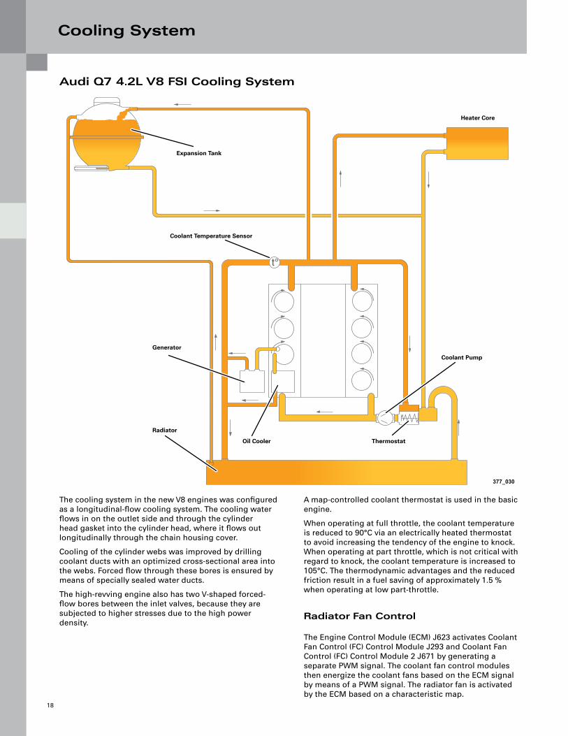
Audi Q7 4 .2L V8 FSI Cooling System
The cooling system in the new V8 engines was configured as a longitudinal-flow cooling system. The cooling water flows in on the outlet side and through the cylinder head gasket into the cylinder head, where it flows out longitudinally through the chain housing cover.
Cooling of the cylinder webs was improved by drilling coolant ducts with an optimized cross-sectional area into the webs. Forced flow through these bores is ensured by means of specially sealed water ducts.
The high-revving engine also has two V-shaped forced-flow bores between the inlet valves, because they are subjected to higher stresses due to the high power density.
A map-controlled coolant thermostat is used in the basic engine.
When operating at full throttle, the coolant temperature is reduced to 90°C via an electrically heated thermostat to avoid increasing the tendency of the engine to knock. When operating at part throttle, which is not critical with regard to knock, the coolant temperature is increased to 105°C. The thermodynamic advantages and the reduced friction result in a fuel saving of approximately 1.5 % when operating at low part-throttle.
Radiator Fan Control
The Engine Control Module (ECM) J623 activates Coolant Fan Control (FC) Control Module J293 and Coolant Fan Control (FC) Control Module 2 J671 by generating a separate PWM signal. The coolant fan control modules then energize the coolant fans based on the ECM signal by means of a PWM signal. The radiator fan is activated by the ECM based on a characteristic map.
t°
377_030
Expansion Tank
Coolant Temperature Sensor
Generator
Radiator
Oil Cooler Thermostat
Coolant Pump
Heater Core

Cooling System
19
Audi RS4 4 .2L V8 FSI Cooling System
Coolant Pump and Thermostat
The 4.2L V8 FSI engine in the RS4 does not use the map-controlled thermostat as found in the Audi Q7 engine.
To achieve more effective cooling, two additional coolers are used. Coolant flows continuously through one of the additional coolers. The second additional cooler is opened via a coolant thermostat.
To avoid excessive heating-up after shutting off the hot engine, the coolant run-on pump is activated a preset period of time after the engine is shut off. The pump run-on time and the need for additional activation of both radiator fans are determined on the basis of characteristic maps. Various measured quantities are included in the calculation (engine temperature, ambient temperature, engine oil temperature and fuel consumption).
t°
377_031
Coolant Thermostat for Additional Cooler
Additional Cooler, Right Additional Cooler, Left
After-Run Coolant Pump V51
Non-return Valve
377_034
Coolant Pump
Thermostat
Generator
Oil Cooler Thermostat
Coolant Pump
Air Circulation System
20
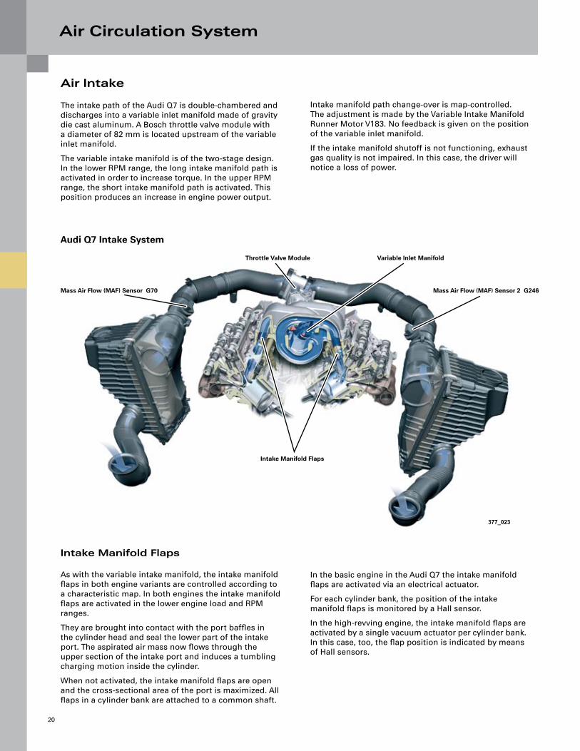
Air Intake
The intake path of the Audi Q7 is double-chambered and discharges into a variable inlet manifold made of gravity die cast aluminum. A Bosch throttle valve module with a diameter of 82 mm is located upstream of the variable inlet manifold.
The variable intake manifold is of the two-stage design. In the lower RPM range, the long intake manifold path is activated in order to increase torque. In the upper RPM range, the short intake manifold path is activated. This position produces an increase in engine power output.
Intake manifold path change-over is map-controlled. The adjustment is made by the Variable Intake Manifold Runner Motor V183. No feedback is given on the position of the variable inlet manifold.
If the intake manifold shutoff is not functioning, exhaust gas quality is not impaired. In this case, the driver will notice a loss of power.
Intake Manifold Flaps
As with the variable intake manifold, the intake manifold flaps in both engine variants are controlled according to a characteristic map. In both engines the intake manifold flaps are activated in the lower engine load and RPM ranges.
They are brought into contact with the port baffles in the cylinder head and seal the lower part of the intake port. The aspirated air mass now flows through the upper section of the intake port and induces a tumbling charging motion inside the cylinder.
When not activated, the intake manifold flaps are open and the cross-sectional area of the port is maximized. All flaps in a cylinder bank are attached to a common shaft.
In the basic engine in the Audi Q7 the intake manifold flaps are activated via an electrical actuator.
For each cylinder bank, the position of the intake manifold flaps is monitored by a Hall sensor.
In the high-revving engine, the intake manifold flaps are activated by a single vacuum actuator per cylinder bank. In this case, too, the flap position is indicated by means of Hall sensors.
377_023
Audi Q7 Intake System
Mass Air Flow (MAF) Sensor G70
Throttle Valve Module Variable Inlet Manifold
Mass Air Flow (MAF) Sensor 2 G246
Intake Manifold Flaps
Air Circulation System
21
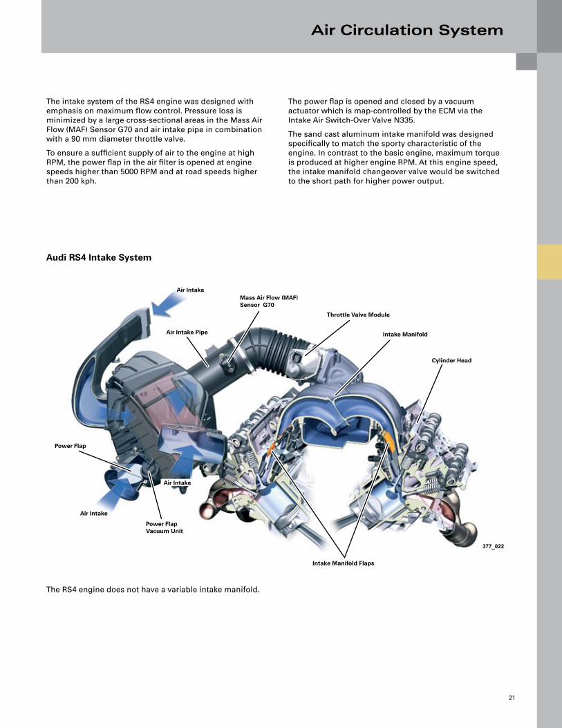
The intake system of the RS4 engine was designed with emphasis on maximum flow control. Pressure loss is minimized by a large cross-sectional areas in the Mass Air Flow (MAF) Sensor G70 and air intake pipe in combination with a 90 mm diameter throttle valve.
To ensure a sufficient supply of air to the engine at high RPM, the power flap in the air filter is opened at engine speeds higher than 5000 RPM and at road speeds higher than 200 kph.
The power flap is opened and closed by a vacuum actuator which is map-controlled by the ECM via the Intake Air Switch-Over Valve N335.
The sand cast aluminum intake manifold was designed specifically to match the sporty characteristic of the engine. In contrast to the basic engine, maximum torque is produced at higher engine RPM. At this engine speed, the intake manifold changeover valve would be switched to the short path for higher power output.
377_022
Audi RS4 Intake System
Air IntakeMass Air Flow (MAF) Sensor G70
Throttle Valve Module
Intake Manifold
Cylinder Head
Intake Manifold Flaps
The RS4 engine does not have a variable intake manifold.
Power Flap Vacuum Unit
Air Intake Pipe
Air Intake
Air Intake
Power Flap

Air Circulation System
22
Audi RS4 Vacuum Hoses
The conventional method of supplying vacuum to the brake servo and the engine components is problematic in the case of FSI engines.
This means that connecting a vacuum line downstream of the throttle valve would not supply the needed vacuum. This is due to the fact that in many engine operating situations, the wide open throttle valve would result in low mass flow rates and vacuum in the intake manifold.
Secondary Air Injection (AIR) Pump Motor V101 Air Filter Filter Housing Flap
Combination Valve Vacuum Unit
Activated Charcoal Canister
Evaporative Emission (EVAP) Canister Purge Regulator Valve N80
Intake Air Switch-Over Valve N335
“Mass Air Flow (MAF) Sensor G70”
Suction Jet Pump (entrainment pump) with Integrated Non-return Valve
Intake Manifold Runner Control (IMRC) Valve N316
Intake Manifold Flaps Vacuum Units
Secondary Air Injection (AIR) Solenoid Valve N112
Non-return Valve
Brake System Vacuum Pump V192
Vacuum Reservoir Brake Servo Brake Booster Pressure Sensor G294 with Non-return Valve
Brake Booster Relay J569
A
B
Air Circulation System
23
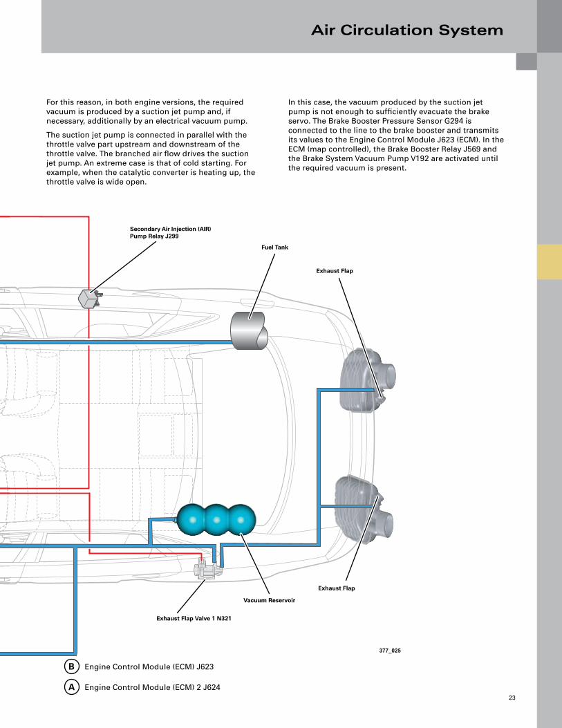
For this reason, in both engine versions, the required vacuum is produced by a suction jet pump and, if necessary, additionally by an electrical vacuum pump.
The suction jet pump is connected in parallel with the throttle valve part upstream and downstream of the throttle valve. The branched air flow drives the suction jet pump. An extreme case is that of cold starting. For example, when the catalytic converter is heating up, the throttle valve is wide open.
In this case, the vacuum produced by the suction jet pump is not enough to sufficiently evacuate the brake servo. The Brake Booster Pressure Sensor G294 is connected to the line to the brake booster and transmits its values to the Engine Control Module J623 (ECM). In the ECM (map controlled), the Brake Booster Relay J569 and the Brake System Vacuum Pump V192 are activated until the required vacuum is present.
Secondary Air Injection (AIR) Pump Relay J299
Fuel Tank
Exhaust Flap
Exhaust Flap
Exhaust Flap Valve 1 N321
Vacuum Reservoir
Engine Control Module (ECM) J623
Engine Control Module (ECM) 2 J624A
B
377_025

Air Circulation System
24
Audi Q7 Vacuum Hoses
Secondary Air Pump
Brake System Vacuum Pump V192
Suction Jet Pump (entrainment pump) with Non-return Valve
Combination Valve A
A
Brake Servo Brake Booster Pressure Sensor G294
Brake Booster Relay J569
Engine Control Module (ECM) J623
Air Filter Evaporator Casing Extraction Valve
Air Circulation System
25
377_068
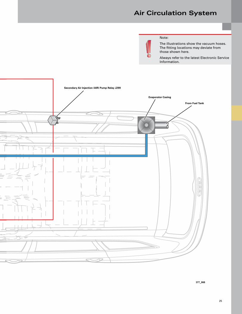
Note:
The illustrations show the vacuum hoses. The fitting locations may deviate from those shown here.
Always refer to the latest Electronic Service Information.
Secondary Air Injection (AIR) Pump Relay J299
Evaporator Casing
From Fuel Tank

Fuel System
26
Audi Q7/RS4 Fuel System
Reference:For a description of the system’s operating mode, refer to SSP 992403 – The 2005 Audi A6 Engines and Transmissions. The main difference with this system is that it uses two high-pressure pumps.
Fuel Metering Valve 2 N402
High-pressure Fuel Pump 2
High-pressure Fuel Pump 1
Low Fuel Pressure Sensor G410
Fuel Metering Valve N290
Leakage Line
Audi Q7 Low-pressure System
Fuel Filter
Audi RS4 Low-pressure System
High Pressure
Low Pressure
Depressurized
Fuel System
27
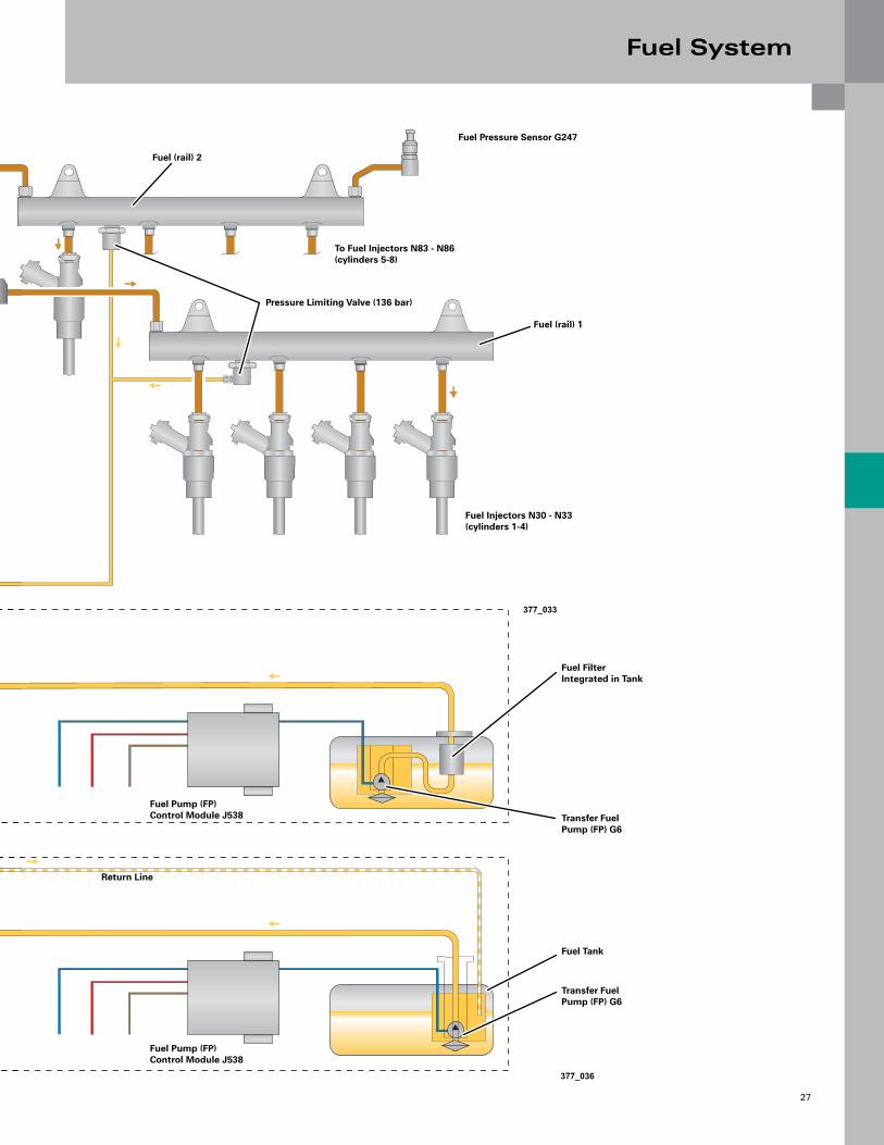
377_036
Fuel (rail) 2
Fuel (rail) 1
Fuel Pressure Sensor G247
Fuel Injectors N30 - N33 (cylinders 1-4)
To Fuel Injectors N83 - N86 (cylinders 5-8)
Pressure Limiting Valve (136 bar)
Fuel Filter Integrated in Tank
Fuel Tank
Transfer Fuel Pump (FP) G6
Fuel Pump (FP) Control Module J538
Return Line
Fuel Pump (FP) Control Module J538 Transfer Fuel
Pump (FP) G6
377_033
Exhaust System
28
Exhaust System
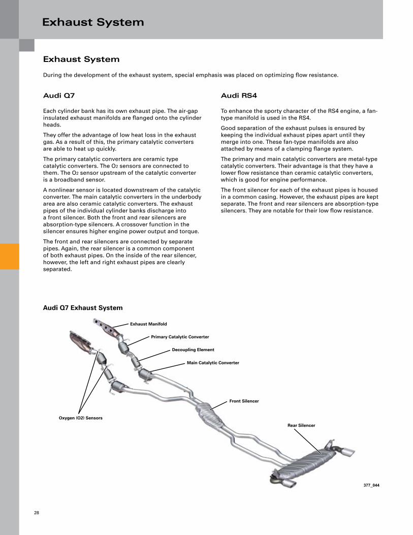
During the development of the exhaust system, special emphasis was placed on optimizing flow resistance.
Audi Q7
Each cylinder bank has its own exhaust pipe. The air-gap insulated exhaust manifolds are flanged onto the cylinder heads.
They offer the advantage of low heat loss in the exhaust gas. As a result of this, the primary catalytic converters are able to heat up quickly.
The primary catalytic converters are ceramic type catalytic converters. The O2 sensors are connected to them. The O2 sensor upstream of the catalytic converter is a broadband sensor.
A nonlinear sensor is located downstream of the catalytic converter. The main catalytic converters in the underbody area are also ceramic catalytic converters. The exhaust pipes of the individual cylinder banks discharge into a front silencer. Both the front and rear silencers are absorption-type silencers. A crossover function in the silencer ensures higher engine power output and torque.
The front and rear silencers are connected by separate pipes. Again, the rear silencer is a common component of both exhaust pipes. On the inside of the rear silencer, however, the left and right exhaust pipes are clearly separated.
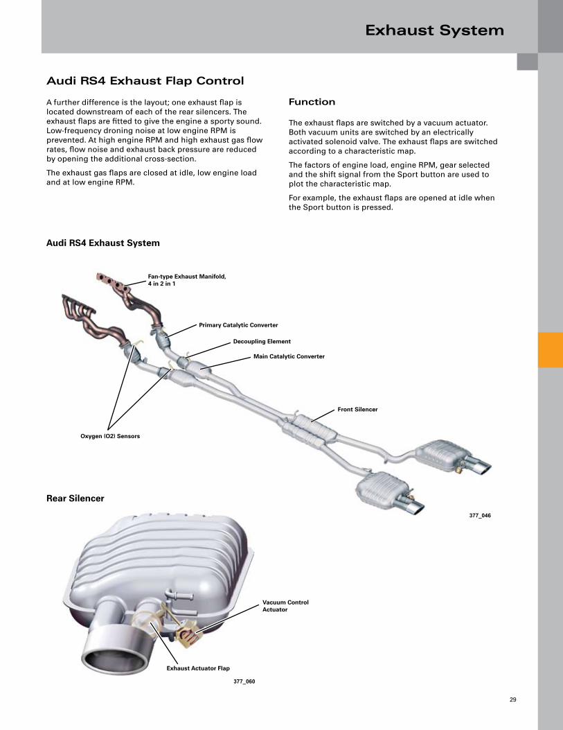
Audi RS4
To enhance the sporty character of the RS4 engine, a fan-type manifold is used in the RS4.
Good separation of the exhaust pulses is ensured by keeping the individual exhaust pipes apart until they merge into one. These fan-type manifolds are also attached by means of a clamping flange system.
The primary and main catalytic converters are metal-type catalytic converters. Their advantage is that they have a lower flow resistance than ceramic catalytic converters, which is good for engine performance.
The front silencer for each of the exhaust pipes is housed in a common casing. However, the exhaust pipes are kept separate. The front and rear silencers are absorption-type silencers. They are notable for their low flow resistance.
377_044
Audi Q7 Exhaust System
Exhaust Manifold
Primary Catalytic Converter
Decoupling Element
Main Catalytic Converter
Front Silencer
Rear Silencer
Oxygen (O2) Sensors
Exhaust System
29
Audi RS4 Exhaust Flap Control
A further difference is the layout; one exhaust flap is located downstream of each of the rear silencers. The exhaust flaps are fitted to give the engine a sporty sound. Low-frequency droning noise at low engine RPM is prevented. At high engine RPM and high exhaust gas flow rates, flow noise and exhaust back pressure are reduced by opening the additional cross-section.
The exhaust gas flaps are closed at idle, low engine load and at low engine RPM.
Function
The exhaust flaps are switched by a vacuum actuator. Both vacuum units are switched by an electrically activated solenoid valve. The exhaust flaps are switched according to a characteristic map.
The factors of engine load, engine RPM, gear selected and the shift signal from the Sport button are used to plot the characteristic map.
For example, the exhaust flaps are opened at idle when the Sport button is pressed.
377_046
377_060
Audi RS4 Exhaust System
Fan-type Exhaust Manifold, 4 in 2 in 1
Primary Catalytic Converter
Decoupling Element
Main Catalytic Converter
Front Silencer
Oxygen (O2) Sensors
Rear Silencer
Exhaust Actuator Flap
Vacuum Control Actuator
Exhaust System
30
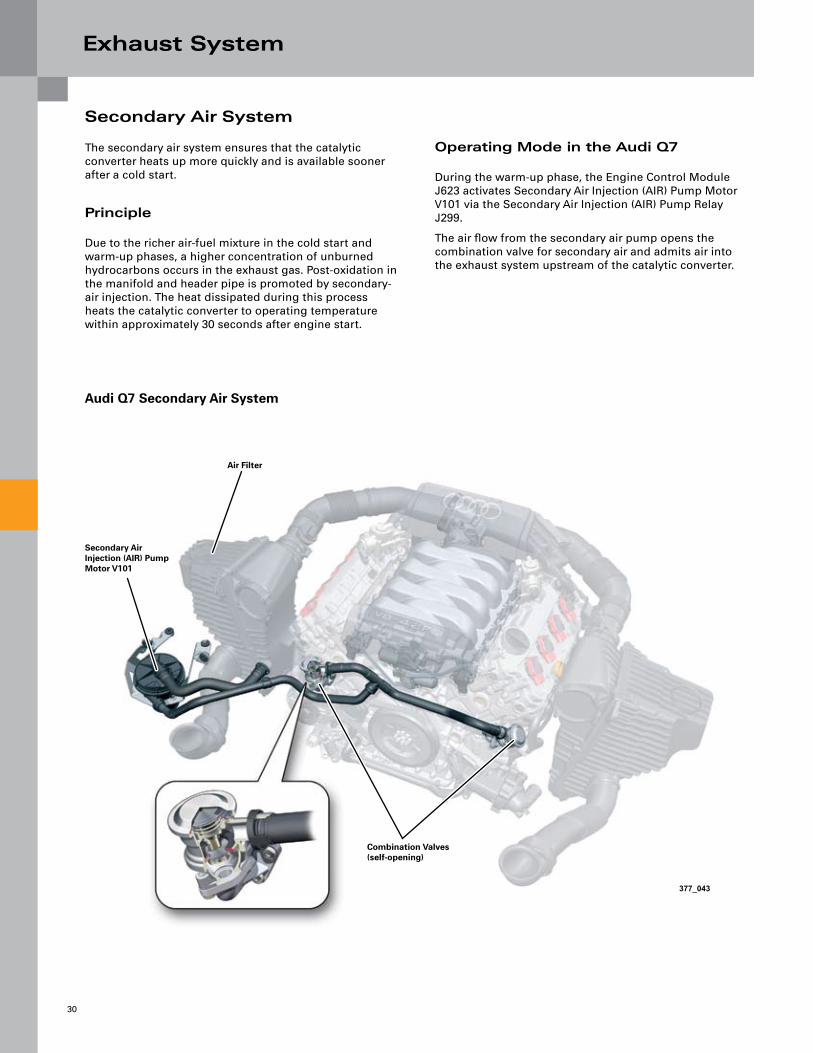
Secondary Air System
The secondary air system ensures that the catalytic converter heats up more quickly and is available sooner after a cold start.
Principle
Due to the richer air-fuel mixture in the cold start and warm-up phases, a higher concentration of unburned hydrocarbons occurs in the exhaust gas. Post-oxidation in the manifold and header pipe is promoted by secondary-air injection. The heat dissipated during this process heats the catalytic converter to operating temperature within approximately 30 seconds after engine start.
Operating Mode in the Audi Q7
During the warm-up phase, the Engine Control Module J623 activates Secondary Air Injection (AIR) Pump Motor V101 via the Secondary Air Injection (AIR) Pump Relay J299.
The air flow from the secondary air pump opens the combination valve for secondary air and admits air into the exhaust system upstream of the catalytic converter.
377_043
Audi Q7 Secondary Air System
Air Filter
Secondary Air Injection (AIR) Pump Motor V101
Combination Valves (self-opening)

Exhaust System
31
Operating Mode in the RS4
The secondary air system operates in much the same way as that in the Audi Q7 engine. The difference here lies in the way the combination valves open and close.
The air path from the secondary air pump to the secondary air duct in the cylinder head is opened by means of a vacuum unit on the combination valve. The vacuum unit is controlled by the Secondary Air Injection (AIR) Solenoid Valve N112 via the ECM.
The basic engine in the Audi Q7 and the high-revving engine in the RS4 have different fitting locations for the secondary air system. In the Audi Q7, the secondary air system is fitted at the engine front end on the input side of the ribbed V-belt, while in the RS4 it is fitted at the output end of the engine.
Audi RS4 Secondary Air System
Air Filter
Combination Valve with Vacuum Unit (vacuum controlled)
Secondary Air Injection (AIR) Solenoid Valve N112
Secondary Air Pump
Reference:For a description of the operating mode this system, please refer to SSP 921903 – The V8-5V Engine, Construction Features and Functions.

Engine Management
32
System Overview – Audi Q7 (Boxch MED 9 .1 .1)
Sensors
Mass Air Flow (MAF) Sensor G70 Mass Air Flow (MAF) Sensor 2 G246 Intake Air Temperature (IAT) Sensor G42
PowerTrain CAN Data Bus
Engine Control Module (ECM) J623
Throttle Position (TP) Sensor G79 Accelerator Pedal Position Sensor 2 G185
Engine Speed (RPM) Sensor G28
Knock Sensors (KS) 1-4 G61, G66, G198, G199
Fuel Pressure Sensor G247
Intake Manifold Runner Position Sensor G336 Intake Manifold Runner Position Sensor 2 G512
Camshaft Position (CMP) Sensor G40 Camshaft Position (CMP) Sensor 2+3 G163 ,G300 Camshaft Position (CMP) Sensor 4 G301
Low Fuel Pressure Sensor G410
Engine Coolant Temperature (ECT) Sensor G62
Throttle Valve Control Module J338 Throttle Drive Angle Sensors 1+2 for Electronic Power Control (EPC) G187, G188
Heated Oxygen Sensor (HO2S) G39 Heated Oxygen Sensor (HO2S) 2 G108 Oxygen Sensor (O2S) Behind Three Way Catalytic Converter (TWC) G130 Oxygen Sensor (O2S) 2 Behind Three Way Catalytic Converter (TWC) G131
Engine Coolant Temperature (ECT) Sensor (on Radiator) G83
Brake Light Switch F Brake Pedal Switch F47
Brake Booster Pressure Sensor G294
Additional signals:Terminal 50/50R Brake Servo Access/Start Control Module J518 Cruise Signal from Steering Column Electronic Systems Control Module J527 Door Contact Wake-up from Comfort System Central Control Module J393 Multi-Function Transmission Range (TR) Switch F125 Auxiliary Heater Wake-up via Climatronic Control Module J255
Engine Management
33
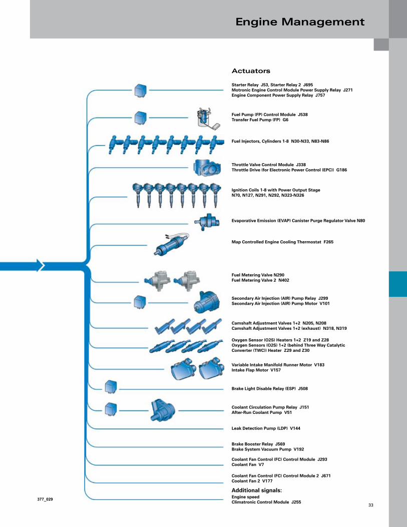
Actuators
Starter Relay J53, Starter Relay 2 J695 Motronic Engine Control Module Power Supply Relay J271 Engine Component Power Supply Relay J757
Fuel Pump (FP) Control Module J538 Transfer Fuel Pump (FP) G6
Fuel Injectors, Cylinders 1-8 N30-N33, N83-N86
Throttle Valve Control Module J338 Throttle Drive (for Electronic Power Control (EPC)) G186
Ignition Coils 1-8 with Power Output Stage N70, N127, N291, N292, N323-N326
Evaporative Emission (EVAP) Canister Purge Regulator Valve N80
Map Controlled Engine Cooling Thermostat F265
Fuel Metering Valve N290 Fuel Metering Valve 2 N402
Secondary Air Injection (AIR) Pump Relay J299 Secondary Air Injection (AIR) Pump Motor V101
Camshaft Adjustment Valves 1+2 N205, N208 Camshaft Adjustment Valves 1+2 (exhaust) N318, N319
Oxygen Sensor (O2S) Heaters 1+2 Z19 and Z28 Oxygen Sensors (O2S) 1+2 (behind Three Way Catalytic Converter (TWC)) Heater Z29 and Z30
Variable Intake Manifold Runner Motor V183 Intake Flap Motor V157
Brake Light Disable Relay (ESP) J508
Coolant Circulation Pump Relay J151 After-Run Coolant Pump V51
Leak Detection Pump (LDP) V144
Brake Booster Relay J569 Brake System Vacuum Pump V192
Coolant Fan Control (FC) Control Module J293 Coolant Fan V7
Coolant Fan Control (FC) Control Module 2 J671 Coolant Fan 2 V177
Additional signals:Engine speed Climatronic Control Module J255
377_029
Engine Management
34
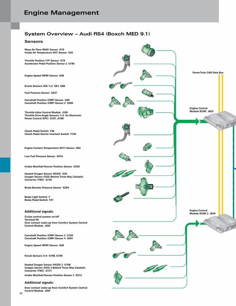
System Overview – Audi RS4 (Boxch MED 9 .1)
Sensors
Mass Air Flow (MAF) Sensor G70 Intake Air Temperature (IAT) Sensor G42
Throttle Position (TP) Sensor G79 Accelerator Pedal Position Sensor 2 G185
Engine Speed (RPM) Sensor G28
Knock Sensors (KS) 1+2 G61, G66
Fuel Pressure Sensor G247
Camshaft Position (CMP) Sensor G40 Camshaft Position (CMP) Sensor 3 G300
Throttle Valve Control Module J338 Throttle Drive Angle Sensors 1+2 for Electronic Power Control (EPC) G187, G188
Clutch Pedal Switch F36 Clutch Pedal Starter Interlock Switch F194
Engine Coolant Temperature (ECT) Sensor G62
Low Fuel Pressure Sensor G410
Intake Manifold Runner Position Sensor G336
Heated Oxygen Sensor (HO2S) G39 Oxygen Sensor (O2S) Behind Three Way Catalytic Converter (TWC) G130
Brake Booster Pressure Sensor G294
Brake Light Switch F Brake Pedal Switch F47
Additional signals:Cruise control system on/off Terminal 50 Door contact wake-up from Comfort System Central Control Module J393
Camshaft Position (CMP) Sensor 2 G163 Camshaft Position (CMP) Sensor 4 G301
Engine Speed (RPM) Sensor G28
Knock Sensors 3+4 G198, G199
Heated Oxygen Sensor (HO2S) 2 G108 Oxygen Sensor (O2S) 2 Behind Three Way Catalytic Converter (TWC) G131
Intake Manifold Runner Position Sensor 2 G512
Additional signals:Door contact wake-up from Comfort System Central Control Module J393
PowerTrain CAN Data Bus
Engine Control Module (ECM) J623
Engine Control Module (ECM) 2 J624
Engine Management
35377_032
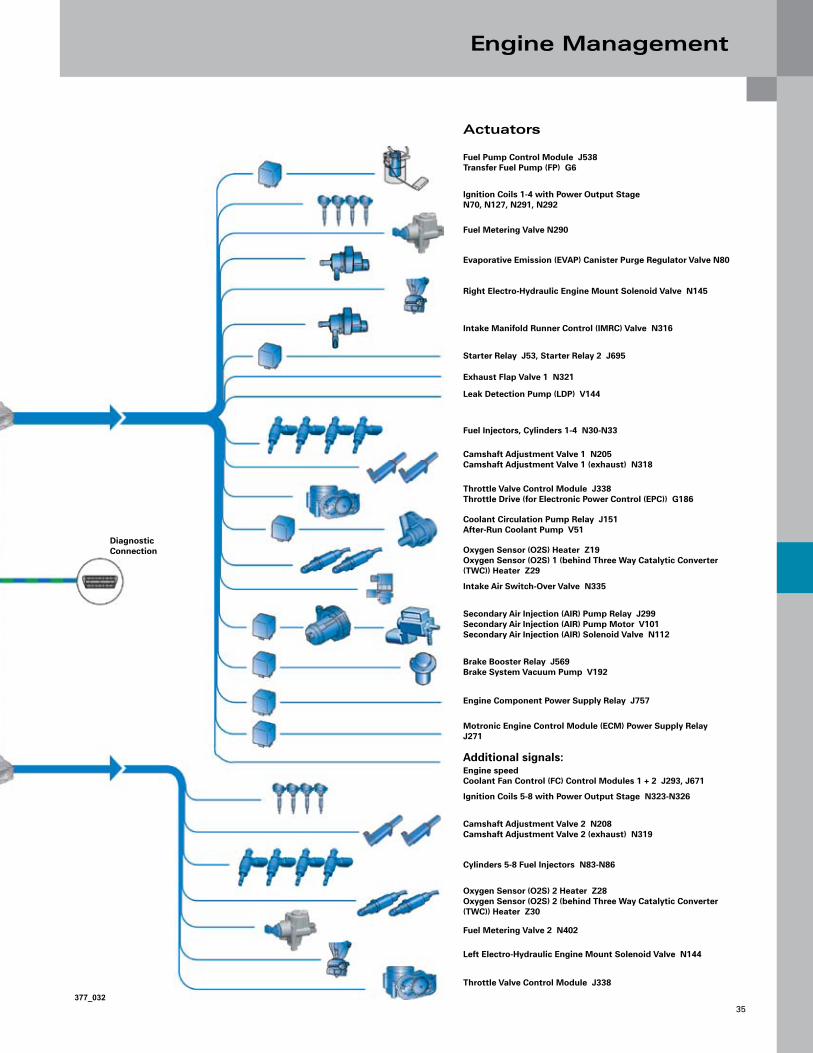
Actuators
Fuel Pump Control Module J538 Transfer Fuel Pump (FP) G6
Diagnostic Connection
Ignition Coils 1-4 with Power Output Stage N70, N127, N291, N292
Fuel Metering Valve N290
Evaporative Emission (EVAP) Canister Purge Regulator Valve N80
Right Electro-Hydraulic Engine Mount Solenoid Valve N145
Intake Manifold Runner Control (IMRC) Valve N316
Starter Relay J53, Starter Relay 2 J695
Exhaust Flap Valve 1 N321
Leak Detection Pump (LDP) V144
Fuel Injectors, Cylinders 1-4 N30-N33
Camshaft Adjustment Valve 1 N205 Camshaft Adjustment Valve 1 (exhaust) N318
Throttle Valve Control Module J338 Throttle Drive (for Electronic Power Control (EPC)) G186
Coolant Circulation Pump Relay J151 After-Run Coolant Pump V51
Oxygen Sensor (O2S) Heater Z19 Oxygen Sensor (O2S) 1 (behind Three Way Catalytic Converter (TWC)) Heater Z29
Intake Air Switch-Over Valve N335
Secondary Air Injection (AIR) Pump Relay J299 Secondary Air Injection (AIR) Pump Motor V101 Secondary Air Injection (AIR) Solenoid Valve N112
Brake Booster Relay J569 Brake System Vacuum Pump V192
Engine Component Power Supply Relay J757
Motronic Engine Control Module (ECM) Power Supply Relay J271
Additional signals:Engine speed Coolant Fan Control (FC) Control Modules 1 + 2 J293, J671
Ignition Coils 5-8 with Power Output Stage N323-N326
Camshaft Adjustment Valve 2 N208 Camshaft Adjustment Valve 2 (exhaust) N319
Cylinders 5-8 Fuel Injectors N83-N86
Oxygen Sensor (O2S) 2 Heater Z28 Oxygen Sensor (O2S) 2 (behind Three Way Catalytic Converter (TWC)) Heater Z30
Fuel Metering Valve 2 N402
Left Electro-Hydraulic Engine Mount Solenoid Valve N144
Throttle Valve Control Module J338

Engine Management
36
Engine management in the new 4.2L V8 FSI is by two versions of the Bosch MED 9.1.1.
A single control module is used in the Audi Q7 engine. There are two control modules for the RS4 engine. A master-slave concept is required here due to the requisite processing power at engine speeds up to 8250 RPM.
Further differences between the Audi Q7 and RS4 engines with respect to engine management are as follows:
Engine Speed Sensor G28
An inductive sender is used in the Audi Q7 engine. A Hall effect sensor is used in the RS4 engine with master/slave concept.
The signal from the Hall sensor can, unlike the signal from the inductive sender, be split with the result that it can be utilized by both engine control modules.
Applying the signal directly to both engine control modules ensures that the control modules are absolutely synchronized.
Throttle Valve Module
The Bosch throttle valve module used in the Audi Q7 is the largest in the range with a diameter of 82 mm. The Pierburg system was selected because the air intake system in the RS4 has a diameter of 90 mm. However, both systems work in exactly the same way.
Spark Plugs
In contrast to the Audi Q7, spark plugs with a higher heat rating (colder plugs)* are used because the RS4 engine is subjected to higher thermal stresses.
* applies to NGK spark plugs
Injectors
Due to the higher fuel demand and the shorter window of time available for injection at very high engine speeds, the RS4 engine is fitted with larger injectors than the Audi Q7 engine.
Diagnosis
The RS4 engine is diagnosed via the K-wire. The Audi Q7 is diagnosed via the powertrain CAN bus.
The processor operates at a clock frequency of 56 MHz. The internal memory has a storage capacity of 512 Kilobytes. Each of the two external memories has a storage capacity of two megabytes.
The connection to the vehicle network is made by means of a CAN data bus.
In the case of the master-slave concept, data is additionally exchanged across a private bus.
377_067
377_065
377_066
377_071
Engine Management
37
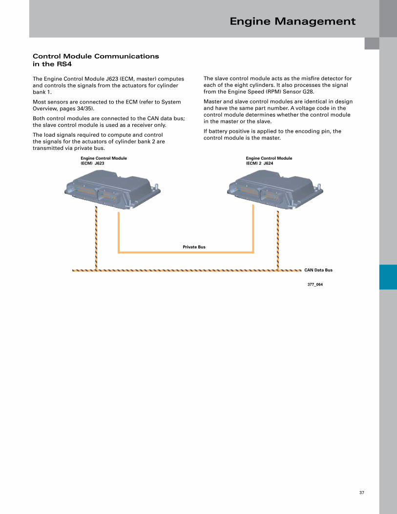
Control Module Communications in the RS4
The Engine Control Module J623 (ECM, master) computes and controls the signals from the actuators for cylinder bank 1.
Most sensors are connected to the ECM (refer to System Overview, pages 34/35).
Both control modules are connected to the CAN data bus; the slave control module is used as a receiver only.
The load signals required to compute and control the signals for the actuators of cylinder bank 2 are transmitted via private bus.
The slave control module acts as the misfire detector for each of the eight cylinders. It also processes the signal from the Engine Speed (RPM) Sensor G28.
Master and slave control modules are identical in design and have the same part number. A voltage code in the control module determines whether the control module in the master or the slave.
If battery positive is applied to the encoding pin, the control module is the master.
377_064
Engine Control Module (ECM) J623
Engine Control Module (ECM) 2 J624
Private Bus
CAN Data Bus
Engine Management
38
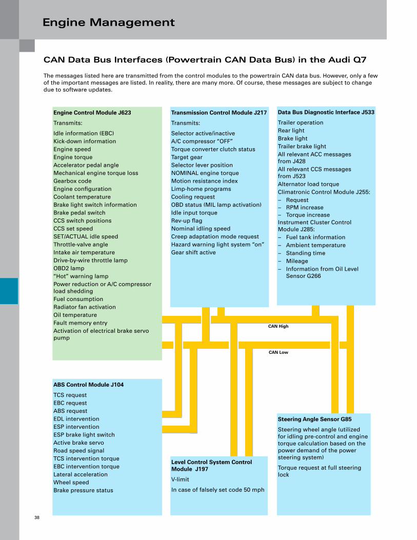
CAN Data Bus Interfaces (Powertrain CAN Data Bus) in the Audi Q7
The messages listed here are transmitted from the control modules to the powertrain CAN data bus. However, only a few of the important messages are listed. In reality, there are many more. Of course, these messages are subject to change due to software updates.
Steering Angle Sensor G85
Steering wheel angle (utilized for idling pre-control and engine torque calculation based on the power demand of the power steering system)
Torque request at full steering lock
ABS Control Module J104
TCS requestEBC requestABS requestEDL interventionESP interventionESP brake light switchActive brake servoRoad speed signalTCS intervention torqueEBC intervention torqueLateral accelerationWheel speedBrake pressure status
Engine Control Module J623
Transmits:
Idle information (EBC)Kick-down informationEngine speedEngine torqueAccelerator pedal angleMechanical engine torque lossGearbox codeEngine configurationCoolant temperatureBrake light switch informationBrake pedal switchCCS switch positionsCCS set speedSET/ACTUAL idle speedThrottle-valve angleIntake air temperatureDrive-by-wire throttle lampOBD2 lamp“Hot” warning lampPower reduction or A/C compressor load sheddingFuel consumptionRadiator fan activationOil temperatureFault memory entryActivation of electrical brake servo pump
Transmission Control Module J217
Transmits:
Selector active/inactiveA/C compressor “OFF”Torque converter clutch statusTarget gearSelector lever positionNOMINAL engine torqueMotion resistance indexLimp-home programsCooling requestOBD status (MIL lamp activation)Idle input torqueRev-up flagNominal idling speedCreep adaptation mode requestHazard warning light system “on”Gear shift active
Data Bus Diagnostic Interface J533
Trailer operationRear lightBrake lightTrailer brake lightAll relevant ACC messages from J428All relevant CCS messages from J523Alternator load torqueClimatronic Control Module J255:
RequestRPM increaseTorque increase
Instrument Cluster Control Module J285:
Fuel tank informationAmbient temperatureStanding timeMileageInformation from Oil Level Sensor G266
–––
–––––
Level Control System Control Module J197
V-limit
In case of falsely set code 50 mph
CAN High
CAN Low
Engine Management
39
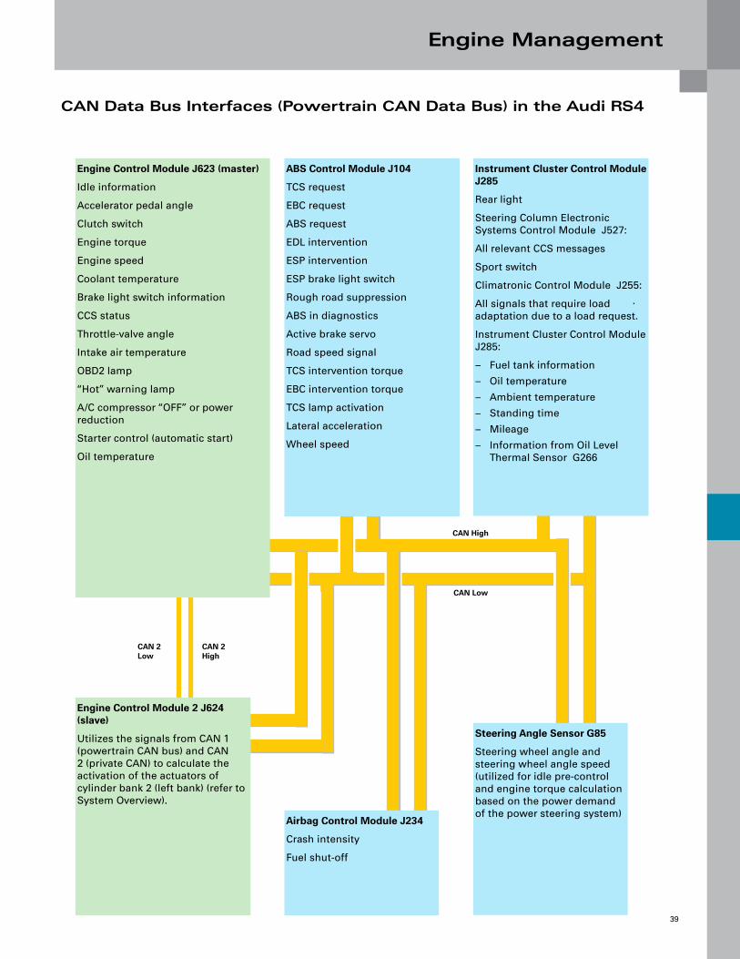
CAN Data Bus Interfaces (Powertrain CAN Data Bus) in the Audi RS4
Engine Control Module 2 J624 (slave)
Utilizes the signals from CAN 1 (powertrain CAN bus) and CAN 2 (private CAN) to calculate the activation of the actuators of cylinder bank 2 (left bank) (refer to System Overview).
ABS Control Module J104
TCS request
EBC request
ABS request
EDL intervention
ESP intervention
ESP brake light switch
Rough road suppression
ABS in diagnostics
Active brake servo
Road speed signal
TCS intervention torque
EBC intervention torque
TCS lamp activation
Lateral acceleration
Wheel speed
Engine Control Module J623 (master)
Idle information
Accelerator pedal angle
Clutch switch
Engine torque
Engine speed
Coolant temperature
Brake light switch information
CCS status
Throttle-valve angle
Intake air temperature
OBD2 lamp
“Hot” warning lamp
A/C compressor “OFF” or power reduction
Starter control (automatic start)
Oil temperature
Steering Angle Sensor G85
Steering wheel angle and steering wheel angle speed (utilized for idle pre-control and engine torque calculation based on the power demand of the power steering system)
Instrument Cluster Control Module J285
Rear light
Steering Column Electronic Systems Control Module J527:
All relevant CCS messages
Sport switch
Climatronic Control Module J255:
All signals that require load adaptation due to a load request.
Instrument Cluster Control Module J285:
Fuel tank information
Oil temperature
Ambient temperature
Standing time
Mileage
Information from Oil Level Thermal Sensor G266
–
–
–
–
–
–
Airbag Control Module J234
Crash intensity
Fuel shut-off
.
CAN High
CAN Low
CAN 2 High
CAN 2 Low
Engine Management
40
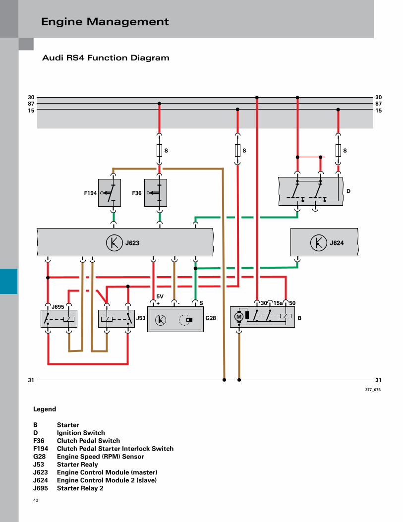
Audi RS4 Function Diagram
377_076
F194 F36
J53 G28 B
D
J695
S
5V+ - S 30 15a 50
308715
31
M
308715
31
S
J623 J624
S
Legend
B StarterD Ignition SwitchF36 Clutch Pedal SwitchF194 Clutch Pedal Starter Interlock SwitchG28 Engine Speed (RPM) SensorJ53 Starter RealyJ623 Engine Control Module (master)J624 Engine Control Module 2 (slave)J695 Starter Relay 2

Engine Management
41
Audi RS4 Sport Mode
To accentuate the sporty character of the RS4, the driver can switch Sport mode “on” or “off” using a special switch. When the Sport program button is pressed the following in-vehicle functions are activated:
More direct accelerator pedal response
More sporty exhaust system set-up
When Sport mode is activated, an indicator lamp illuminates in the dash panel insert. Sport mode is deactivated when the ignition is turned off.
–
–
Accelerator Pedal Function (Throttle Progression)
When Sport mode is activated, the engine becomes more responsive. At the same time, the characteristic curve of the accelerator pedal is modified in the ECM. This means that, in Sport mode, the requested engine torque is higher than in normal operation in the same accelerator pedal position.
In addition, the comfort-oriented “soft” engine torque curve is suppressed. As a result, the engine responds immediately to pressure on the accelerator pedal.
377_077 377_078
10 20 30 40 50 60 70 80 90 100
10
0
20
30
40
50
60
70
80
90
100
110
Accelerator Position
Normal Operation
Sport Mode
Req
ues
ted
Tor
qu
e in
%
Exhaust Flap Control
After the Sport mode is activated, unlike in normal operation, the exhaust flaps in the rear silencer are opened when the engine is idling. This emphasizes the sporty sound of the RS4 engine.
After engine speed is increased, however, the exhaust flaps are closed again. This ensures that the vehicle meets the statutory noise emission limits.
Reopening of the exhaust flaps while driving is speed and load dependent, and is regulated on the basis of a characteristic map.


Knowledge Assessment
43
An on-line Knowledge Assessment (exam) is available for this Self-Study Program.
The Knowledge Assessment may or may not be required for Certification.
You can find this Knowledge Assessment at:
www.accessaudi.com
For assistance, please call:
Audi Academy
Learning Management Center Headquarters
1-877-AUDI-LMC (283-4562)
(8:00 a.m. to 8:00 p.m. EST)

Self-Study Program 911403
All rights reserved. Technical specificationssubject to change withoutnotice.
Audi of America, Inc.3800 Hamlin RoadAuburn Hills, Michigan 48326
Diagnosis with VAS Scan Tools
Service Training
Vorsprung durch Technik www.audiusa.com
Vehicle Self-Diagnosis
VAS 5052
HelpPrint
ApplicationsAdministration
OBD
Te stInstruments
Guided FaultFinding
Guided Functions
Vehicle Diagnostic-, measuring- and information systemVersion -USA/CDN- / V07.00.00 19/08/2004
Top Related