


Languages
Pages
Legal

Effective November 2011Supersedes October 2011
Bulletin HY30-5503-M1UK
Service Manual Series F11
wwwcomosocom
2 Parker HannifinPump and Motor DivisionTrollhaumlttan Sweden
Service ManualSeries F11
Bulletin HY30-5503-M1UK
Offer of SalePlease contact your Parker representation for a detailed rdquoOffer of Salerdquo
FAILURE OR IMPROPER SELECTION OR IMPROPER USE OF THE PRODUCTS ANDOR SYSTEMS DESCRIBED HEREIN OR RELATED ITEMS CAN CAUSE DEATH PERSONAL INJURY AND PROPERTY DAMAGE
This document and other information from Parker Hannifin Corporation its subsidiaries and authorized distributors provide product andor system options for further investigation by users having technical expertise It is important that you analyze all aspects of your application including consequences of any failure and review the information concerning the product or sys-tem in the current product catalogue Due to the variety of operating conditions and applications for these products or systems the user through its own analysis and testing is solely responsible for making the final selection of the products and systems and assuring that all performance safety and warning requirements of the application are met
The products described herein including without limitation product features specifications designs availability and pricing are subject to change by Parker Hannifin Corporation and its subsidiaries at any time without notice
List of contents PageGeneral information 3Specification and Operating Temperature 4Design 5Operational Check 6Assembly 7 - 10Barrel Retaining Ring 11Torque and Gear Backlash 12Split view 13Parts specification 14Saw Motor and Make Up Valve 15Valve Plates 16
Conversion factors1 kg = 22046 lb1 N = 022481 lbf1 bar = 14504 psi1 l = 021997 UK gallon1 l = 026417 US gallon1 cm3 = 0061024 in3
1 m = 32808 feet1 mm = 003937 in1 degC = 18degF + 32
WARNING
wwwcomosocom
3 Parker HannifinPump and Motor DivisionTrollhaumlttan Sweden
Service ManualSeries F11
Bulletin HY30-5503-M1UK
General information
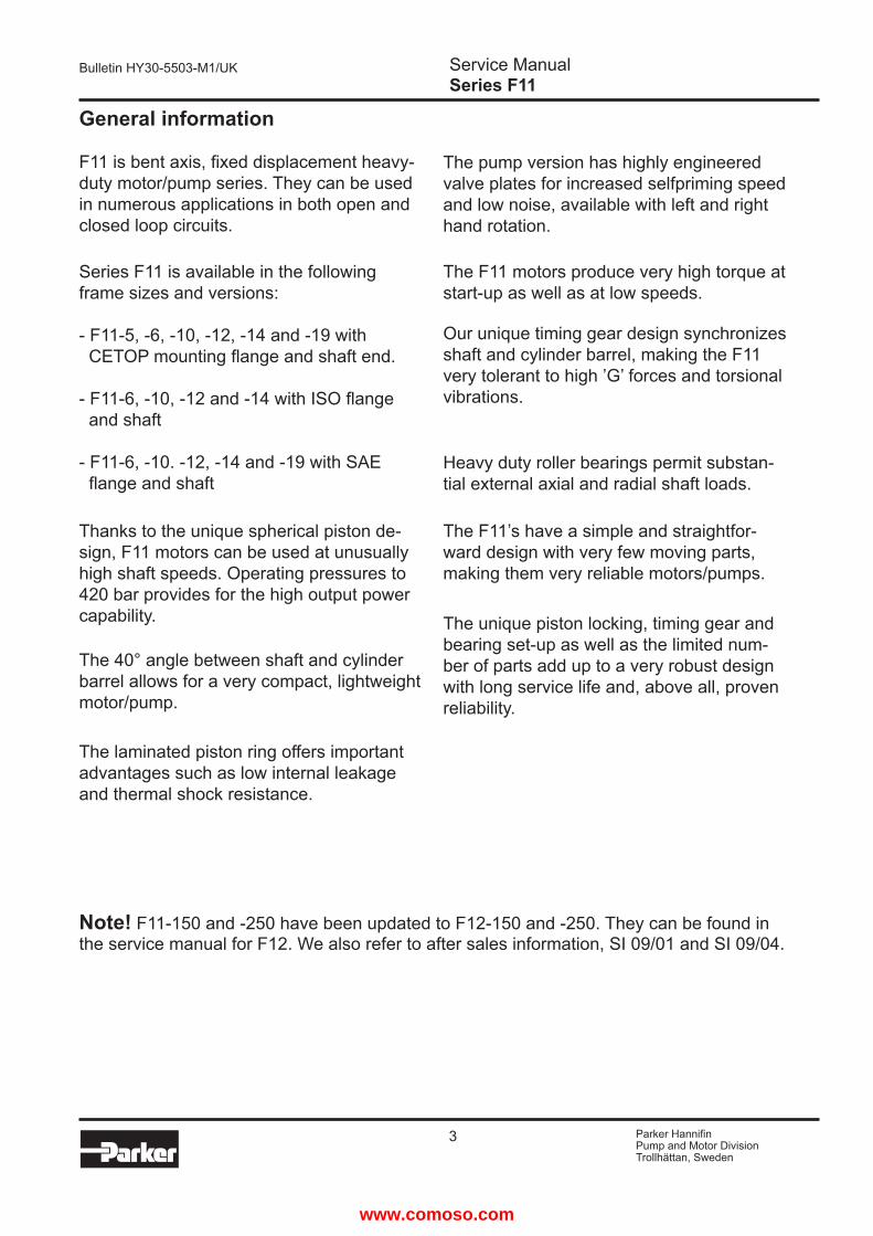
F11 is bent axis fixed displacement heavy-duty motorpump series They can be used in numerous applications in both open and closed loop circuits
Series F11 is available in the following frame sizes and versions
- F11-5 -6 -10 -12 -14 and -19 with CETOP mounting flange and shaft end
- F11-6 -10 -12 and -14 with ISO flange and shaft
- F11-6 -10 -12 -14 and -19 with SAE flange and shaft
Thanks to the unique spherical piston de-sign F11 motors can be used at unusually high shaft speeds Operating pressures to 420 bar provides for the high output power capability
The 40deg angle between shaft and cylinder barrel allows for a very compact lightweight motorpump
The laminated piston ring offers important advantages such as low internal leakage and thermal shock resistance
The pump version has highly engineered valve plates for increased selfpriming speed and low noise available with left and right hand rotation
The F11 motors produce very high torque at start-up as well as at low speeds
Our unique timing gear design synchronizes shaft and cylinder barrel making the F11 very tolerant to high rsquoGrsquo forces and torsional vibrations
Heavy duty roller bearings permit substan-tial external axial and radial shaft loads
The F11rsquos have a simple and straightfor-ward design with very few moving parts making them very reliable motorspumps
The unique piston locking timing gear and bearing set-up as well as the limited num-ber of parts add up to a very robust design with long service life and above all proven reliability
Note F11-150 and -250 have been updated to F12-150 and -250 They can be found in the service manual for F12 We also refer to after sales information SI 0901 and SI 0904
wwwcomosocom
4 Parker HannifinPump and Motor DivisionTrollhaumlttan Sweden
Service ManualSeries F11
Bulletin HY30-5503-M1UK
1) Intermittent max 6 seconds in any one minute2) Self priming speed valid at sea level
SpecificationsSize F11 -5 -6 -10 -12 -14 -19
Displacement (cm3rev) 49 60 98 125 143 190
Operating Pressure (bar) Max intermittent 1) Max continuous
420350
420350
420350
420350
420350
420350
Motor operating speed (rpm) Max intermittent 1) Max continuous Min continuous
1400012800
50
1120010200
50
1120010200
50
103009400
50
99009000
50
89008100
50
Max pump self priming speed (rpm) L or R operation 2) 4600 - 4200 3900 3900 3500
Motor input flow (lmin)Max intermittent 1) Max continuous
6963
6761
110100
129118
142129
169154
Main circuit temp Max (degC)Min (degC)
80-40
80-40
80-40
80-40
80-40
80-40
Mass moment of inertia (x10 -3) (kg m2) 78 95 156 198 227 302
Weight (kg) 47 75 75 82 83 11
Operating temperatureThe following temperatures should not be exceeded(Type N shaft seals) Drain fluid 90 degC
FPM shaft seals (type V) can be used to 115 degC drain fluid temperature
Note The temperature should be measured at the utilized drain port
Continuous operation may require case flushing inorder to meet the viscosity and temperature limitations
For further information we refer toCatalogue HY30-8249UK
wwwcomosocom
5 Parker HannifinPump and Motor DivisionTrollhaumlttan Sweden
Service ManualSeries F11
Bulletin HY30-5503-M1UK
Design
Series F11 pumpsmotors consist of a rotating group contained in a split housing Spherical pistons (1) with laminated piston rings (2) operate at a 40deg angle relative to the shaft (3) As the shaft turns the pistons are driven in a reciprocating movement in the cylinder barrel (4) When the unit is used as a pump the oil passes from the inlet port to the cylinder barrel and is then forced to the outlet port through the pumping action of the pistonsA barrel retaining ring maintains the barrel against the valve plate (5) A ring gear (6) on the shaft meshes with the corresponding teeth of the cylinder barrel (4) so that the cylinder barrel always rotates at the same speed as the shaft (3) The shaft is supported by two heavy duty tapered roller bearings (7)
1
2 3
5
4
7
6
wwwcomosocom
6 Parker HannifinPump and Motor DivisionTrollhaumlttan Sweden
Service ManualSeries F11
Bulletin HY30-5503-M1UK
Operational Check
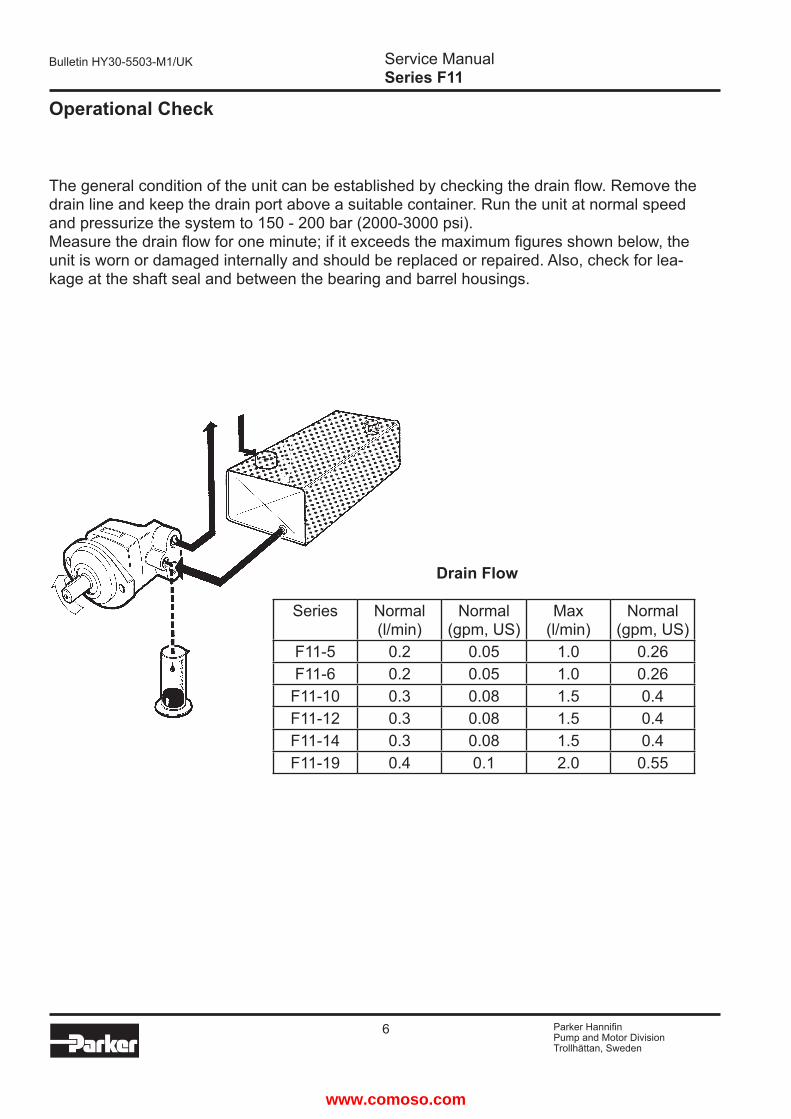
The general condition of the unit can be established by checking the drain flow Remove the drain line and keep the drain port above a suitable container Run the unit at normal speed and pressurize the system to 150 - 200 bar (2000-3000 psi)Measure the drain flow for one minute if it exceeds the maximum figures shown below the unit is worn or damaged internally and should be replaced or repaired Also check for lea-kage at the shaft seal and between the bearing and barrel housings
Drain Flow
Series Normal (lmin)
Normal(gpm US)
Max(lmin)
Normal(gpm US)
F11-5 02 005 10 026F11-6 02 005 10 026
F11-10 03 008 15 04F11-12 03 008 15 04F11-14 03 008 15 04F11-19 04 01 20 055
wwwcomosocom
7 Parker HannifinPump and Motor DivisionTrollhaumlttan Sweden
Service ManualSeries F11
Bulletin HY30-5503-M1UK
Assembling
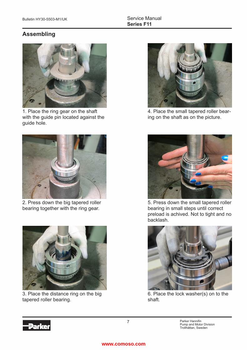
1 Place the ring gear on the shaft with the guide pin located against the guide hole
2 Press down the big tapered roller bearing together with the ring gear
3 Place the distance ring on the big tapered roller bearing
4 Place the small tapered roller bear-ing on the shaft as on the picture
5 Press down the small tapered roller bearing in small steps until correct preload is achived Not to tight and no backlash
6 Place the lock washer(s) on to the shaft
wwwcomosocom
8 Parker HannifinPump and Motor DivisionTrollhaumlttan Sweden
Service ManualSeries F11
Bulletin HY30-5503-M1UK
Assembling
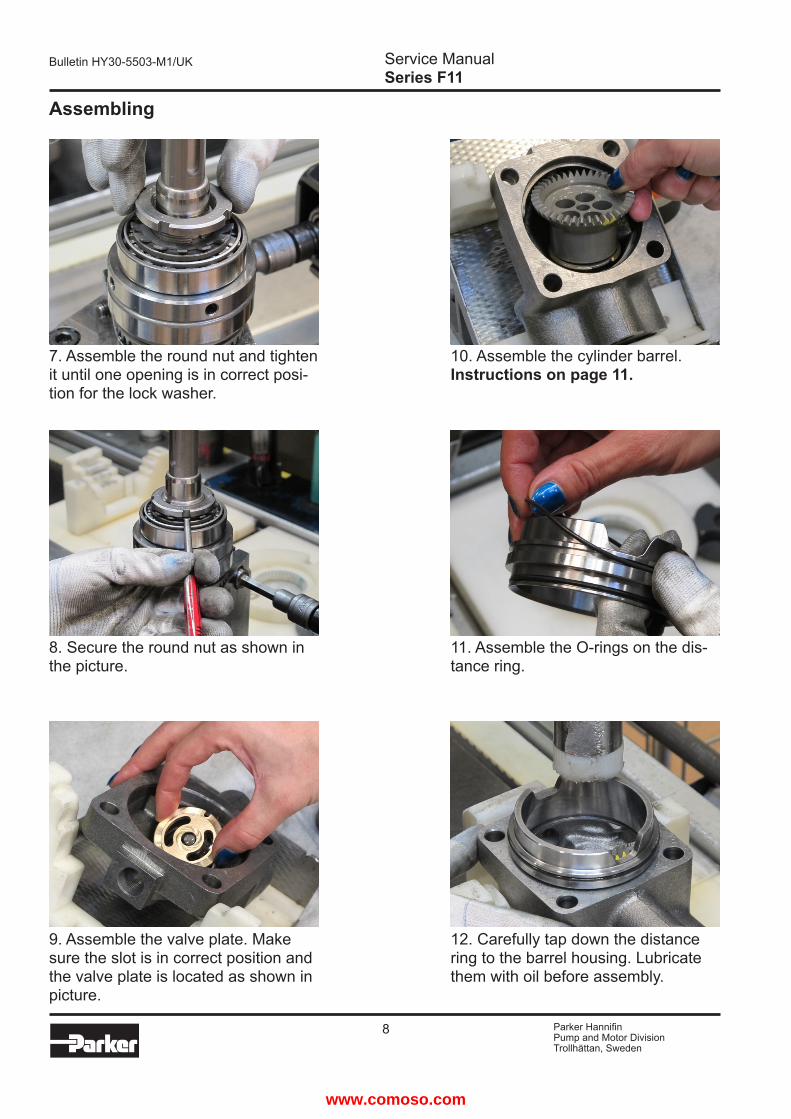
7 Assemble the round nut and tighten it until one opening is in correct posi-tion for the lock washer
10 Assemble the cylinder barrel Instructions on page 11
8 Secure the round nut as shown in the picture
11 Assemble the O-rings on the dis-tance ring
9 Assemble the valve plate Make sure the slot is in correct position and the valve plate is located as shown in picture
12 Carefully tap down the distance ring to the barrel housing Lubricate them with oil before assembly
wwwcomosocom
9 Parker HannifinPump and Motor DivisionTrollhaumlttan Sweden
Service ManualSeries F11
Bulletin HY30-5503-M1UK
Assembling
13 Assemble the shims
14 Assemble the pistons Lubricate the ball sockets before assembly
15 Assemble the shaft package with pistons in to the cylinder barrel
16 Make sure the timing is correct
17 Carefully tap down the bearing housing
18 Lubricate the sealing surface on the shaft before assembling the shaft seal
wwwcomosocom
10 Parker HannifinPump and Motor DivisionTrollhaumlttan Sweden
Service ManualSeries F11
Bulletin HY30-5503-M1UK
Assembling
19 Carefully push down the shaft seal
20 Place the support ring with the radius agains the dust lip on the shaft seal
21 Carefully tap down shaft seal and support ring
22 Assemble the retaining ring
23 Assemble the hexagon screws and torque them to specified value shown on page 12
24 Tap down the flat key and turn the shaft at least one revolution Make sure the back-lash of the gears are correct (see page 12)
wwwcomosocom
11 Parker HannifinPump and Motor DivisionTrollhaumlttan Sweden
Service ManualSeries F11
Bulletin HY30-5503-M1UK
Barrel retaining ring
1 Assemble the barrel retaining ring Note grooves upwards as on picture
2 When the barrel housing have one groove assemble the cylinder barrel as shown in picture 3
4 When the barrel housing have two grooves assemble the cylinder barrel as shown in picture 5
3 Assemble the cylinder barrel as shown in picture
5 Assemble the cylinder barrel as shown in picture
Connection ports A and B
One groove Two grooves
Opening barrel retaining ring
Opening barrel retaining ring
wwwcomosocom
12 Parker HannifinPump and Motor DivisionTrollhaumlttan Sweden
Service ManualSeries F11
Bulletin HY30-5503-M1UK
Torque
Size Torque (Nm) Torque (lbfft)F11-5 24plusmn4 18plusmn3F11-6 48plusmn8 35plusmn6F11-10 48plusmn8 35plusmn6F11-12 48plusmn8 35plusmn6F11-14 48plusmn8 35plusmn6F11-19 48plusmn8 35plusmn6
Gear BacklashF11-5 through F11-19010 - 025 mm
Frame size R mmF11-5 250F11-6 313F11-10 313F11-12 313F11-14 313F11-19 375
wwwcomosocom
13 Parker HannifinPump and Motor DivisionTrollhaumlttan Sweden
Service ManualSeries F11
Bulletin HY30-5503-M1UK
Split View
492
474
470
464
460
321
440
411431
121
222
310
221
110
132131
491
475
211
237236
233
452
488
486
wwwcomosocom
14 Parker HannifinPump and Motor DivisionTrollhaumlttan Sweden
Service ManualSeries F11
Bulletin HY30-5503-M1UK
Part Specification
Item Title Benaumlmning110 Barrel Housing Trumhus121 Valve Plate Ventilskiva131 Seal Washer Taumltbricka132 Hexagon Plug Insexpropp211 Bearing Housing Lagerhus221 O-ring O-ring222 O-ring O-ring233 Shaft Seal Axeltaumltning236 Back-up Ring Stoumldbricka237 Retaining Ring Sparingrring310 Shaft Axel321 Flat Key Plattkil411 Cylinder Barrel Cylindertrumma431 Barrel Retaining Ring Faumlstring440 Piston Kolv452 Ring Gear Kuggkrans460 Tap Rol Bearing Koniskt Rullager464 Spacer Ring Distansring470 Tap Rol Bearing Koniskt Rullager474 Lock Washer Laringsbricka475 Round Nut Rundmutter486 Guide Spacer Distanshylsa488 Shim Schims491 Hexagon Screw Insexskruv492 Hexagon Screw Insexskruv
wwwcomosocom
15 Parker HannifinPump and Motor DivisionTrollhaumlttan Sweden
Service ManualSeries F11
Bulletin HY30-5503-M1UK
Saw Motor
Parts Specification
Item Title Benaumlmning155 Check Valve Cone Backventilkaumlgla157 Compression Spring Tryckfjaumlder161 Hex Socket Plug Sexkantpropp162 O-ring O-ring166 Adapter Nipple Adapternippel167 O-ring O-ring168 Hexagon Plug assy Insexpropp kpl990 Expanding Plug Expanderplugg992 Grease Fitting Smoumlrjnippel
Right hand rotation shown (CW)
How to change direction of rotation
Move item 154 and 160 to the left side and item 165 and 168 to the right side for left hand rotation (CCW)
Item Torque (Nm)
Torque (lbfft)
161 100plusmn10 74plusmn7166 100plusmn10 74plusmn7168 25plusmn5 18plusmn4992 9plusmn2 7plusmn15
Torque
wwwcomosocom
16 Parker HannifinPump and Motor DivisionTrollhaumlttan Sweden
Service ManualSeries F11
Bulletin HY30-5503-M1UK
Valve PlatesType Description
MSLRQHJG
Bi-directional motor or pump operationBi-directional motor operation high speed bi-metalLeft hand rotation pump operationRight hand rotation pump operationBi-directional motor operation low noiseBi-directional motor operation high pressureRight hand rotation motor operation internal drainLeft hand rotation motor operation internal drain
M
J
Q
H
GR
L
S
NoteThe internal drained valve plates G and J is shown from the back side of the valve plate From the front when installed they looks the same as the M valve plate
wwwcomosocom
17 Parker HannifinPump and Motor DivisionTrollhaumlttan Sweden
Service ManualSeries F11
Bulletin HY30-5503-M1UK
Notes
wwwcomosocom
18 Parker HannifinPump and Motor DivisionTrollhaumlttan Sweden
Service ManualSeries F11
Bulletin HY30-5503-M1UK
Notes
wwwcomosocom
19 Parker HannifinPump and Motor DivisionTrollhaumlttan Sweden
Service ManualSeries F11
Bulletin HY30-5503-M1UK
Notes
wwwcomosocom
Parker HannifinPump and Motor DivisionFlygmotorvaumlgen 2SE-461 82 TrollhaumlttanSwedenTel +46 (0)520 40 45 00Fax +46 (0)520 371 05wwwparkercom
wwwcomosocom
2 Parker HannifinPump and Motor DivisionTrollhaumlttan Sweden
Service ManualSeries F11
Bulletin HY30-5503-M1UK
Offer of SalePlease contact your Parker representation for a detailed rdquoOffer of Salerdquo
FAILURE OR IMPROPER SELECTION OR IMPROPER USE OF THE PRODUCTS ANDOR SYSTEMS DESCRIBED HEREIN OR RELATED ITEMS CAN CAUSE DEATH PERSONAL INJURY AND PROPERTY DAMAGE
This document and other information from Parker Hannifin Corporation its subsidiaries and authorized distributors provide product andor system options for further investigation by users having technical expertise It is important that you analyze all aspects of your application including consequences of any failure and review the information concerning the product or sys-tem in the current product catalogue Due to the variety of operating conditions and applications for these products or systems the user through its own analysis and testing is solely responsible for making the final selection of the products and systems and assuring that all performance safety and warning requirements of the application are met
The products described herein including without limitation product features specifications designs availability and pricing are subject to change by Parker Hannifin Corporation and its subsidiaries at any time without notice
List of contents PageGeneral information 3Specification and Operating Temperature 4Design 5Operational Check 6Assembly 7 - 10Barrel Retaining Ring 11Torque and Gear Backlash 12Split view 13Parts specification 14Saw Motor and Make Up Valve 15Valve Plates 16
Conversion factors1 kg = 22046 lb1 N = 022481 lbf1 bar = 14504 psi1 l = 021997 UK gallon1 l = 026417 US gallon1 cm3 = 0061024 in3
1 m = 32808 feet1 mm = 003937 in1 degC = 18degF + 32
WARNING
wwwcomosocom
3 Parker HannifinPump and Motor DivisionTrollhaumlttan Sweden
Service ManualSeries F11
Bulletin HY30-5503-M1UK
General information
F11 is bent axis fixed displacement heavy-duty motorpump series They can be used in numerous applications in both open and closed loop circuits
Series F11 is available in the following frame sizes and versions
- F11-5 -6 -10 -12 -14 and -19 with CETOP mounting flange and shaft end
- F11-6 -10 -12 and -14 with ISO flange and shaft
- F11-6 -10 -12 -14 and -19 with SAE flange and shaft
Thanks to the unique spherical piston de-sign F11 motors can be used at unusually high shaft speeds Operating pressures to 420 bar provides for the high output power capability
The 40deg angle between shaft and cylinder barrel allows for a very compact lightweight motorpump
The laminated piston ring offers important advantages such as low internal leakage and thermal shock resistance
The pump version has highly engineered valve plates for increased selfpriming speed and low noise available with left and right hand rotation
The F11 motors produce very high torque at start-up as well as at low speeds
Our unique timing gear design synchronizes shaft and cylinder barrel making the F11 very tolerant to high rsquoGrsquo forces and torsional vibrations
Heavy duty roller bearings permit substan-tial external axial and radial shaft loads
The F11rsquos have a simple and straightfor-ward design with very few moving parts making them very reliable motorspumps
The unique piston locking timing gear and bearing set-up as well as the limited num-ber of parts add up to a very robust design with long service life and above all proven reliability
Note F11-150 and -250 have been updated to F12-150 and -250 They can be found in the service manual for F12 We also refer to after sales information SI 0901 and SI 0904
wwwcomosocom
4 Parker HannifinPump and Motor DivisionTrollhaumlttan Sweden
Service ManualSeries F11
Bulletin HY30-5503-M1UK
1) Intermittent max 6 seconds in any one minute2) Self priming speed valid at sea level
SpecificationsSize F11 -5 -6 -10 -12 -14 -19
Displacement (cm3rev) 49 60 98 125 143 190
Operating Pressure (bar) Max intermittent 1) Max continuous
420350
420350
420350
420350
420350
420350
Motor operating speed (rpm) Max intermittent 1) Max continuous Min continuous
1400012800
50
1120010200
50
1120010200
50
103009400
50
99009000
50
89008100
50
Max pump self priming speed (rpm) L or R operation 2) 4600 - 4200 3900 3900 3500
Motor input flow (lmin)Max intermittent 1) Max continuous
6963
6761
110100
129118
142129
169154
Main circuit temp Max (degC)Min (degC)
80-40
80-40
80-40
80-40
80-40
80-40
Mass moment of inertia (x10 -3) (kg m2) 78 95 156 198 227 302
Weight (kg) 47 75 75 82 83 11
Operating temperatureThe following temperatures should not be exceeded(Type N shaft seals) Drain fluid 90 degC
FPM shaft seals (type V) can be used to 115 degC drain fluid temperature
Note The temperature should be measured at the utilized drain port
Continuous operation may require case flushing inorder to meet the viscosity and temperature limitations
For further information we refer toCatalogue HY30-8249UK
wwwcomosocom
5 Parker HannifinPump and Motor DivisionTrollhaumlttan Sweden
Service ManualSeries F11
Bulletin HY30-5503-M1UK
Design
Series F11 pumpsmotors consist of a rotating group contained in a split housing Spherical pistons (1) with laminated piston rings (2) operate at a 40deg angle relative to the shaft (3) As the shaft turns the pistons are driven in a reciprocating movement in the cylinder barrel (4) When the unit is used as a pump the oil passes from the inlet port to the cylinder barrel and is then forced to the outlet port through the pumping action of the pistonsA barrel retaining ring maintains the barrel against the valve plate (5) A ring gear (6) on the shaft meshes with the corresponding teeth of the cylinder barrel (4) so that the cylinder barrel always rotates at the same speed as the shaft (3) The shaft is supported by two heavy duty tapered roller bearings (7)
1
2 3
5
4
7
6
wwwcomosocom
6 Parker HannifinPump and Motor DivisionTrollhaumlttan Sweden
Service ManualSeries F11
Bulletin HY30-5503-M1UK
Operational Check
The general condition of the unit can be established by checking the drain flow Remove the drain line and keep the drain port above a suitable container Run the unit at normal speed and pressurize the system to 150 - 200 bar (2000-3000 psi)Measure the drain flow for one minute if it exceeds the maximum figures shown below the unit is worn or damaged internally and should be replaced or repaired Also check for lea-kage at the shaft seal and between the bearing and barrel housings
Drain Flow
Series Normal (lmin)
Normal(gpm US)
Max(lmin)
Normal(gpm US)
F11-5 02 005 10 026F11-6 02 005 10 026
F11-10 03 008 15 04F11-12 03 008 15 04F11-14 03 008 15 04F11-19 04 01 20 055
wwwcomosocom
7 Parker HannifinPump and Motor DivisionTrollhaumlttan Sweden
Service ManualSeries F11
Bulletin HY30-5503-M1UK
Assembling
1 Place the ring gear on the shaft with the guide pin located against the guide hole
2 Press down the big tapered roller bearing together with the ring gear
3 Place the distance ring on the big tapered roller bearing
4 Place the small tapered roller bear-ing on the shaft as on the picture
5 Press down the small tapered roller bearing in small steps until correct preload is achived Not to tight and no backlash
6 Place the lock washer(s) on to the shaft
wwwcomosocom
8 Parker HannifinPump and Motor DivisionTrollhaumlttan Sweden
Service ManualSeries F11
Bulletin HY30-5503-M1UK
Assembling
7 Assemble the round nut and tighten it until one opening is in correct posi-tion for the lock washer
10 Assemble the cylinder barrel Instructions on page 11
8 Secure the round nut as shown in the picture
11 Assemble the O-rings on the dis-tance ring
9 Assemble the valve plate Make sure the slot is in correct position and the valve plate is located as shown in picture
12 Carefully tap down the distance ring to the barrel housing Lubricate them with oil before assembly
wwwcomosocom
9 Parker HannifinPump and Motor DivisionTrollhaumlttan Sweden
Service ManualSeries F11
Bulletin HY30-5503-M1UK
Assembling
13 Assemble the shims
14 Assemble the pistons Lubricate the ball sockets before assembly
15 Assemble the shaft package with pistons in to the cylinder barrel
16 Make sure the timing is correct
17 Carefully tap down the bearing housing
18 Lubricate the sealing surface on the shaft before assembling the shaft seal
wwwcomosocom
10 Parker HannifinPump and Motor DivisionTrollhaumlttan Sweden
Service ManualSeries F11
Bulletin HY30-5503-M1UK
Assembling
19 Carefully push down the shaft seal
20 Place the support ring with the radius agains the dust lip on the shaft seal
21 Carefully tap down shaft seal and support ring
22 Assemble the retaining ring
23 Assemble the hexagon screws and torque them to specified value shown on page 12
24 Tap down the flat key and turn the shaft at least one revolution Make sure the back-lash of the gears are correct (see page 12)
wwwcomosocom
11 Parker HannifinPump and Motor DivisionTrollhaumlttan Sweden
Service ManualSeries F11
Bulletin HY30-5503-M1UK
Barrel retaining ring
1 Assemble the barrel retaining ring Note grooves upwards as on picture
2 When the barrel housing have one groove assemble the cylinder barrel as shown in picture 3
4 When the barrel housing have two grooves assemble the cylinder barrel as shown in picture 5
3 Assemble the cylinder barrel as shown in picture
5 Assemble the cylinder barrel as shown in picture
Connection ports A and B
One groove Two grooves
Opening barrel retaining ring
Opening barrel retaining ring
wwwcomosocom
12 Parker HannifinPump and Motor DivisionTrollhaumlttan Sweden
Service ManualSeries F11
Bulletin HY30-5503-M1UK
Torque
Size Torque (Nm) Torque (lbfft)F11-5 24plusmn4 18plusmn3F11-6 48plusmn8 35plusmn6F11-10 48plusmn8 35plusmn6F11-12 48plusmn8 35plusmn6F11-14 48plusmn8 35plusmn6F11-19 48plusmn8 35plusmn6
Gear BacklashF11-5 through F11-19010 - 025 mm
Frame size R mmF11-5 250F11-6 313F11-10 313F11-12 313F11-14 313F11-19 375
wwwcomosocom
13 Parker HannifinPump and Motor DivisionTrollhaumlttan Sweden
Service ManualSeries F11
Bulletin HY30-5503-M1UK
Split View
492
474
470
464
460
321
440
411431
121
222
310
221
110
132131
491
475
211
237236
233
452
488
486
wwwcomosocom
14 Parker HannifinPump and Motor DivisionTrollhaumlttan Sweden
Service ManualSeries F11
Bulletin HY30-5503-M1UK
Part Specification
Item Title Benaumlmning110 Barrel Housing Trumhus121 Valve Plate Ventilskiva131 Seal Washer Taumltbricka132 Hexagon Plug Insexpropp211 Bearing Housing Lagerhus221 O-ring O-ring222 O-ring O-ring233 Shaft Seal Axeltaumltning236 Back-up Ring Stoumldbricka237 Retaining Ring Sparingrring310 Shaft Axel321 Flat Key Plattkil411 Cylinder Barrel Cylindertrumma431 Barrel Retaining Ring Faumlstring440 Piston Kolv452 Ring Gear Kuggkrans460 Tap Rol Bearing Koniskt Rullager464 Spacer Ring Distansring470 Tap Rol Bearing Koniskt Rullager474 Lock Washer Laringsbricka475 Round Nut Rundmutter486 Guide Spacer Distanshylsa488 Shim Schims491 Hexagon Screw Insexskruv492 Hexagon Screw Insexskruv
wwwcomosocom
15 Parker HannifinPump and Motor DivisionTrollhaumlttan Sweden
Service ManualSeries F11
Bulletin HY30-5503-M1UK
Saw Motor
Parts Specification
Item Title Benaumlmning155 Check Valve Cone Backventilkaumlgla157 Compression Spring Tryckfjaumlder161 Hex Socket Plug Sexkantpropp162 O-ring O-ring166 Adapter Nipple Adapternippel167 O-ring O-ring168 Hexagon Plug assy Insexpropp kpl990 Expanding Plug Expanderplugg992 Grease Fitting Smoumlrjnippel
Right hand rotation shown (CW)
How to change direction of rotation
Move item 154 and 160 to the left side and item 165 and 168 to the right side for left hand rotation (CCW)
Item Torque (Nm)
Torque (lbfft)
161 100plusmn10 74plusmn7166 100plusmn10 74plusmn7168 25plusmn5 18plusmn4992 9plusmn2 7plusmn15
Torque
wwwcomosocom
16 Parker HannifinPump and Motor DivisionTrollhaumlttan Sweden
Service ManualSeries F11
Bulletin HY30-5503-M1UK
Valve PlatesType Description
MSLRQHJG
Bi-directional motor or pump operationBi-directional motor operation high speed bi-metalLeft hand rotation pump operationRight hand rotation pump operationBi-directional motor operation low noiseBi-directional motor operation high pressureRight hand rotation motor operation internal drainLeft hand rotation motor operation internal drain
M
J
Q
H
GR
L
S
NoteThe internal drained valve plates G and J is shown from the back side of the valve plate From the front when installed they looks the same as the M valve plate
wwwcomosocom
17 Parker HannifinPump and Motor DivisionTrollhaumlttan Sweden
Service ManualSeries F11
Bulletin HY30-5503-M1UK
Notes
wwwcomosocom
18 Parker HannifinPump and Motor DivisionTrollhaumlttan Sweden
Service ManualSeries F11
Bulletin HY30-5503-M1UK
Notes
wwwcomosocom
19 Parker HannifinPump and Motor DivisionTrollhaumlttan Sweden
Service ManualSeries F11
Bulletin HY30-5503-M1UK
Notes
wwwcomosocom
Parker HannifinPump and Motor DivisionFlygmotorvaumlgen 2SE-461 82 TrollhaumlttanSwedenTel +46 (0)520 40 45 00Fax +46 (0)520 371 05wwwparkercom
wwwcomosocom
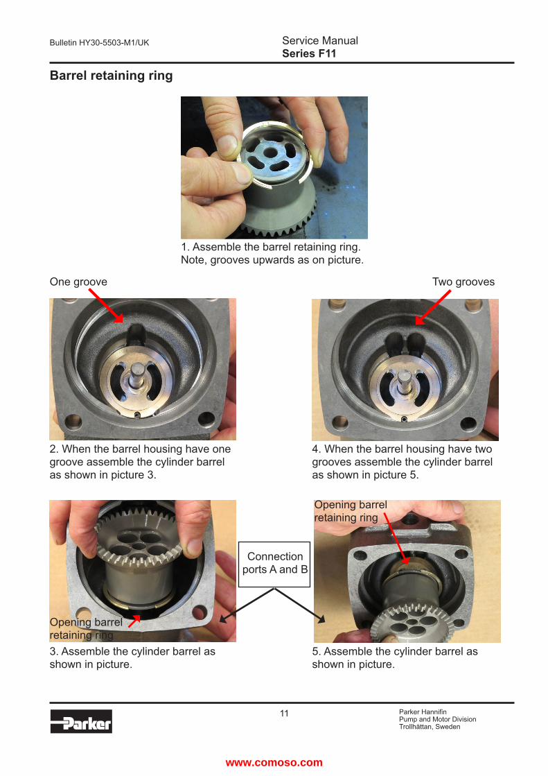
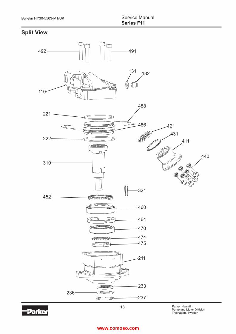
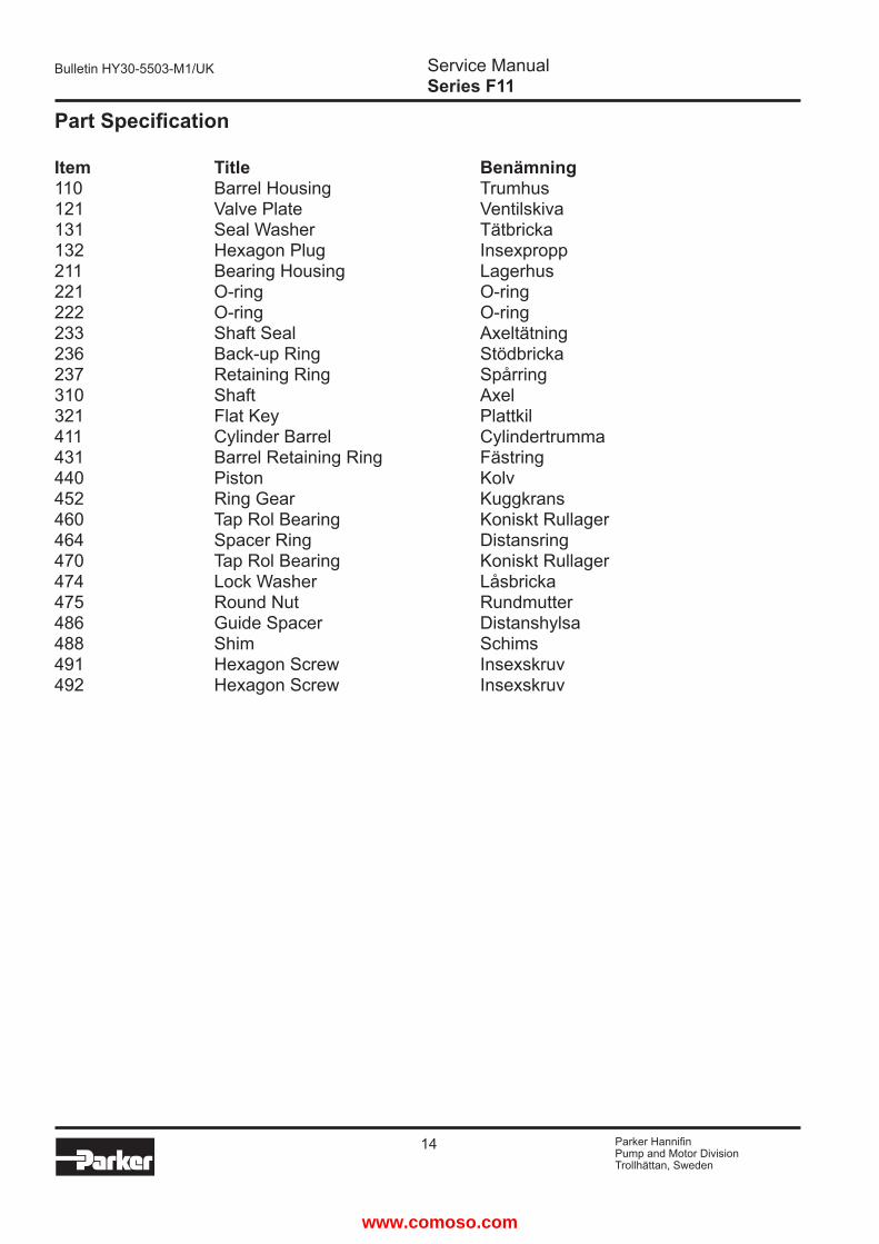
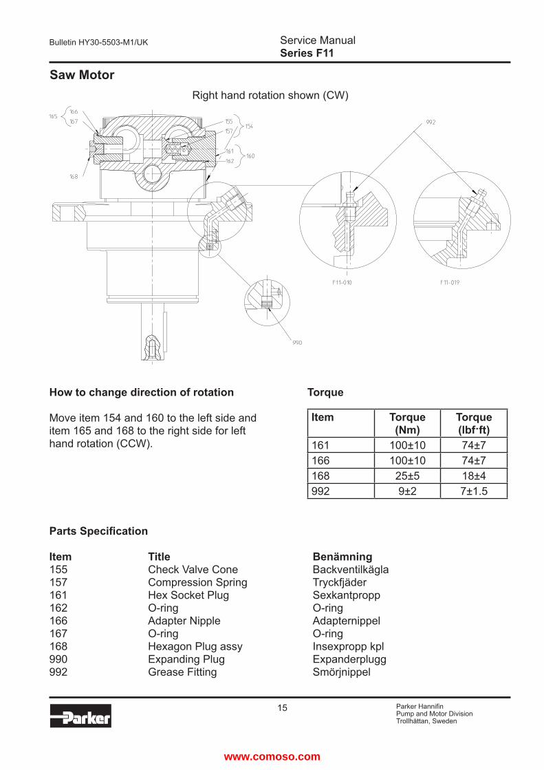
19 Parker HannifinPump and Motor DivisionTrollhaumlttan Sweden
Service ManualSeries F11
Bulletin HY30-5503-M1UK
Notes
wwwcomosocom
Parker HannifinPump and Motor DivisionFlygmotorvaumlgen 2SE-461 82 TrollhaumlttanSwedenTel +46 (0)520 40 45 00Fax +46 (0)520 371 05wwwparkercom
wwwcomosocom

Parker HannifinPump and Motor DivisionFlygmotorvaumlgen 2SE-461 82 TrollhaumlttanSwedenTel +46 (0)520 40 45 00Fax +46 (0)520 371 05wwwparkercom
wwwcomosocom
Top Related