


Languages
Pages
Legal


88
Vibration systems and methods
The systems that use the vibration technique can be divided into the following categories:
• freely oscillating systems, which will be described in this guide
• oscillating systems bound to resonance, which require speci!c in-depth research. Please contact the Technical Sales Service
of Italvibras if these systems are required.
The free oscillation system includes two di"erent methods:
• rotational: the vibrating force is directed in all directions through 360° in a rotational way, either clockwise or anticlockwise.
• unidirectional: the vibrating force is directed in one single direction in fade-free sinoidal reciprocating mode.
The “rotational” method is obtained by using a single electric vibrator.
The “unidirectional” method is obtained by using two electric vibrators with the same electro-mechanical characteristics,
each turning in the opposite direction to the other.
Examples of how electric vibrators are used in di!erent processes
The following examples illustrate a few typical uses:
Unidirectional method
Vibrating force in a single direction, in sinusoidal reciprocating mode.
Rotational method
Vibrating force directed in all directions through 306°, in rotational mode.
SELECTING THE ELECTRIC VIBRATOR
For conveyors, separators,
sieves, sizing machines, un-
loaders, positioners, sorters,
feeders and $uidized beds:
unidirectional method.
For compacting tables and
tests (accelerated ageing,
stress, ecc.): unidirectional
or rotational method.
For compacting tables and
tests (accelerated ageing,
stress, ecc.): rotational
method.
For vibrating beds: rotatio-
nal method.
For !lters: rotational method.
For silos and hoppers:
rotational method.

89
Choice of the vibration method and rotation speed (and, thus, the vibration frequency) of the electric vibrator applied to the elastically insulated machi-ne, depending on the process
The choice of the vibration method and vibration frequency able to achieve the utmost e%ciency for each type of process,
depends on the speci!c weight and granulometry (or piece size) of the material used in the process itself (consult the Table on
page 92).
Regardless of the selected vibration method, the electric vibrators can be mounted on the machine, elastically insulated with
its axis in a horizontal or vertical position or, if necessary, in an intermediate position between the two directrices.
The angle of incidence “i” (measured in degrees) of the line of force in relation to the horizontal plane should be taken into due
consideration when electric vibrators are applied with the “unidirectional” method.
Important: the line of force for any angle of incidence must pass through center of gravity “G” of the elastically insulated ma-
chine (see !gure below).
Determination of the angle of incidence of the line of force depends on the type of process and must be within the indicated
range.
“G”
e
i
VTEOc
=V
teo + V
i
Fα
α
Flow of material Trajectory
Thrust
Particle of material
App
Unidirectional method
Theoretic speed of the product V
teo in m/h or cm/sangle of incidence of the line of
force in relation to the horizontal plane
eccentricity (mm)
peak-to-peak (mm) = 2 x e
Rotational methodCorrected theoretic speed of the product V
TEOc in m/h or cm/s
Flow of material
Calculated according to α (see table on right)
Processes / Uses
for special separators (e.g.: the milling industry);
for conveying, unloading, feeding, positioning and sorting;
for sifting, grading and separating;
for $uidized beds.
“i”
da 6° a 12°
da 25° a 30°
da 31° a 45°
da 45° a 80°
i =
e =
App =
angle of inclination of machine in relation to horizontal plane
angle of incidence = 90 -α
speed of incidence (cm/s or m/h)
corrective factor to calculate corrected theoretic speed VTEOC
eccentricity (mm)
α =
i =
Vi =
Fα =
e =
corrected theoretic speed to take the
slant of the machine into account
Corrected theoretic of the product
VTEOc
=
VTEO
=
Establishedvalue
Values calculatedaccording in α
α i Fα Vi
10° 80° 0,81 80
15° 75° 0,71 75
20° 70° 0,60 70
25° 65° 0,48 65
35° 55° 0,25 55
90
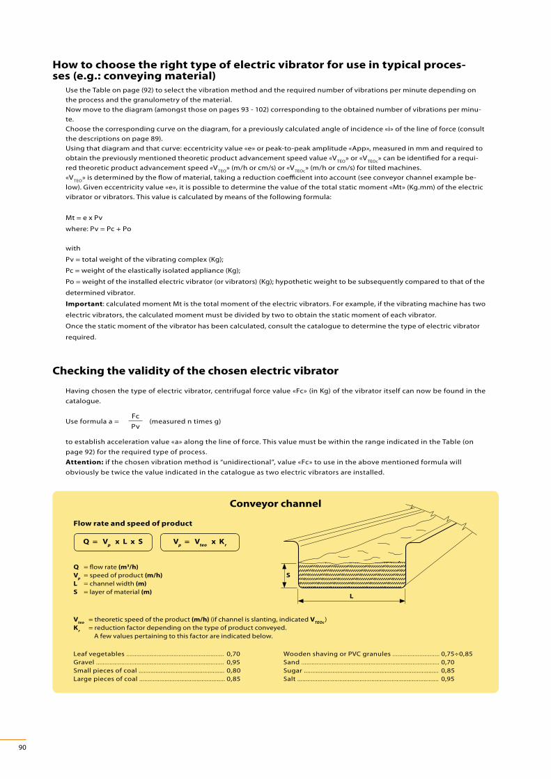
How to choose the right type of electric vibrator for use in typical proces-ses (e.g.: conveying material)
Use the Table on page (92) to select the vibration method and the required number of vibrations per minute depending on
the process and the granulometry of the material.
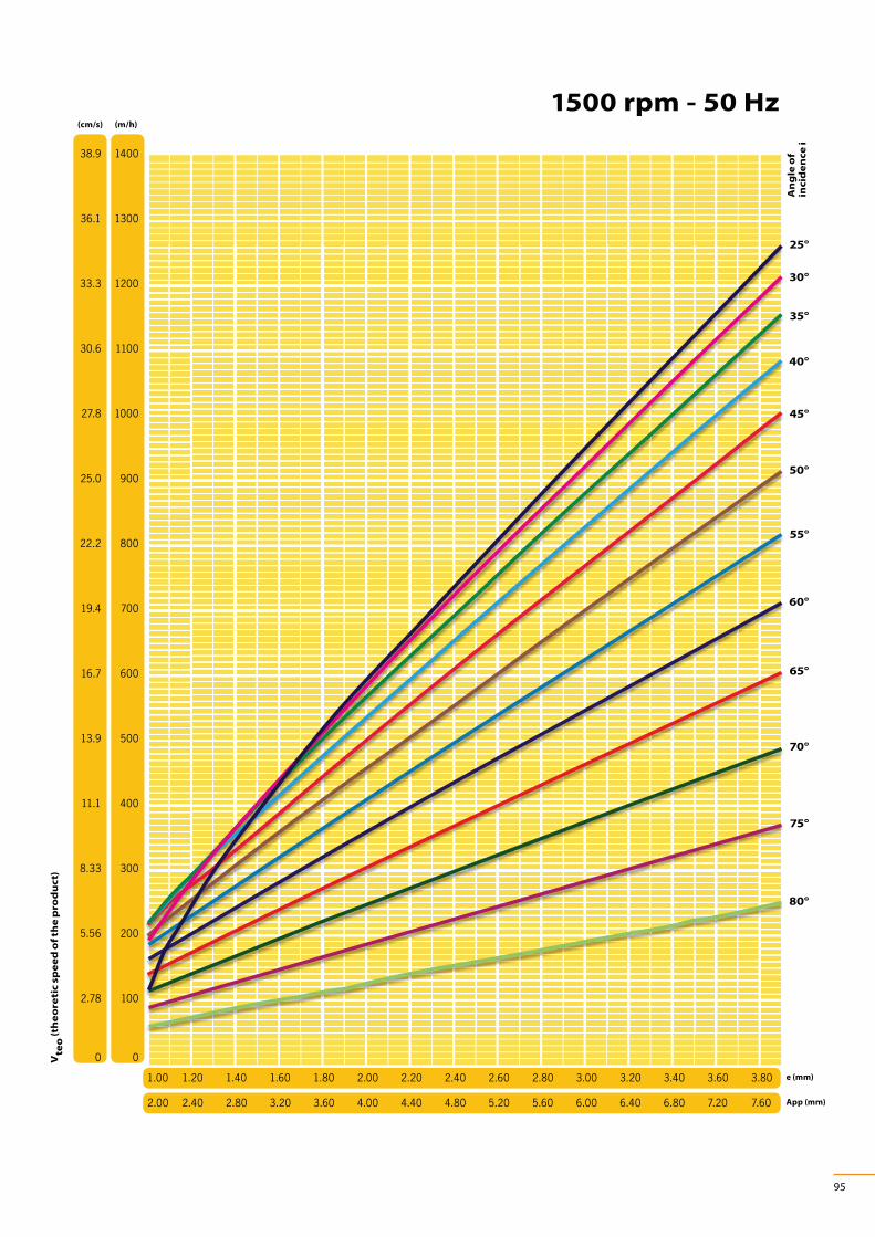
Now move to the diagram (amongst those on pages 93 - 102) corresponding to the obtained number of vibrations per minu-
te.
Choose the corresponding curve on the diagram, for a previously calculated angle of incidence «i» of the line of force (consult
the descriptions on page 89).
Using that diagram and that curve: eccentricity value «e» or peak-to-peak amplitude «App», measured in mm and required to
obtain the previously mentioned theoretic product advancement speed value «VTEO
» or «VTEOc
» can be identi!ed for a requi-
red theoretic product advancement speed «VTEO
» (m/h or cm/s) or «VTEOc
» (m/h or cm/s) for tilted machines.
«VTEO
» is determined by the $ow of material, taking a reduction coe%cient into account (see conveyor channel example be-
low). Given eccentricity value «e», it is possible to determine the value of the total static moment «Mt» (Kg.mm) of the electric
vibrator or vibrators. This value is calculated by means of the following formula:
Mt = e x Pv
where: Pv = Pc + Po
with
Pv = total weight of the vibrating complex (Kg);
Pc = weight of the elastically isolated appliance (Kg);
Po = weight of the installed electric vibrator (or vibrators) (Kg); hypothetic weight to be subsequently compared to that of the
determined vibrator.
Important: calculated moment Mt is the total moment of the electric vibrators. For example, if the vibrating machine has two
electric vibrators, the calculated moment must be divided by two to obtain the static moment of each vibrator.
Once the static moment of the vibrator has been calculated, consult the catalogue to determine the type of electric vibrator
required.
Checking the validity of the chosen electric vibrator
Having chosen the type of electric vibrator, centrifugal force value «Fc» (in Kg) of the vibrator itself can now be found in the
catalogue.
Use formula a = (measured n times g)
to establish acceleration value «a» along the line of force. This value must be within the range indicated in the Table (on
page 92) for the required type of process.
Attention: if the chosen vibration method is “unidirectional”, value «Fc» to use in the above mentioned formula will
obviously be twice the value indicated in the catalogue as two electric vibrators are installed.
Fc
Pv
Q = Vp x L x S V
p = V
teo x K
r
L
S
Flow rate and speed of product
Conveyor channel
Q
Vp
L
S
= $ow rate (m3/h)
= speed of product (m/h)
= channel width (m)
= layer of material (m)
Vteo
Kr
= theoretic speed of the product (m/h) (if channel is slanting, indicated VTEOc
)
= reduction factor depending on the type of product conveyed.
A few values pertaining to this factor are indicated below.
Leaf vegetables ..........................................................
Gravel ............................................................................
Small pieces of coal ...................................................
Large pieces of coal ...................................................
0,70
0,95
0,80
0,85
Wooden shaving or PVC granules ............................
Sand ..................................................................................
Sugar ................................................................................
Salt ....................................................................................
0,75÷0,85
0,70
0,85
0,95

91
100
10
1
0
500 600 700 800 900 1000 1100 1200 1300 1400 1500 1600 1700 1800 3000 3600
r=5
r=3
98,00
96,00
94,00
92,00
90,00
88,00
86,00
84,00
82,00
3,0 3,2 3,4 3,6 3,8 4,0 4,2 4,4 4,6 4,8 5,0 5,2 5,4 5,6 5,8
Mechanical insulation of the vibrating equipment from the bearing struc-ture sizing the elastic systems
If free oscillation systems are used, it is advisable to !t anti-vibration mounts (such as helical steel springs, rubber supports or
pneumatic actuators) to allow the vibrating machine to freely move in all directions.
Do not use connecting rods, leaf springs or $at springs, etc., for free oscillation systems.
The non-vibrating element must be of adequate capacity, able to bear a weight equal to total weight «Pt» (i.e. the sum of the
weights of the elastically insulated machine, or the electric vibrator or vibrators «Pv» and the material bearing on the machi-
ne itself «Ps») multiplied by the factor of safety, the value of which is between 2 and 2.5. Capacity «Q» of the elastic element
will therefore be:
Qkg
= x 2,5 Pv + Ps
N
Pv = total weight of the vibrating complex (Kg)
Ps = static weight of material on machine (Kg)
N = number of anti-vibration mounts
Where
Fle
xio
n f
(m
m)
of
the
ela
sti
c s
yste
m
Diagram A
Electric vibrator rpm
Diagram B
Pe
rce
nta
ge
of
insu
lati
on
I%
Resonance ratio r

92
Now determine the camber «f.»of the elastic system by means of diagram A, depending on the vibration frequency (rpm of
the electric vibrator) and considering a resonance ratio «r.» (between the vibration frequency of the vibrating complex and
the frequency of the elastic system itself) between 3 and 5.
The elastic constant of the anti-vibrating mount thus equals:
The capacity «Qkg
» and the elastic constant «Kkg-mm
» are the two entities required to choose the anti-vibration mounts on
the market.
It is absolutely essential to distribute the load of the vibrating complex evenly over the elastic system.
Diagram B gives the percentage of elastic insulation (I%) between the vibrating structure and bearing structure, depen-
ding on ratio «r».
The anti-vibration mounts must be positioned so that the flexure is the same on all the elements, in order to balance the
machine.
Important: the bearing structure to which the anti-vibration mounts of the vibrating complex are fastened must be rigidly
anchored to the ground or to some other type of bearing structure and always without any further anti-vibration ele-
ments.
where f = $exion of the elastic system (mm)Kkg-mm
= Pv
f x N
Type of process
Sp
ec
i$c
we
igh
t
Sis
e
Vibratingforce Vibrations per minute
Rotat. Gericht.
600(50Hz)
750(50Hz)
1000(50Hz)
1500(50Hz)
3000(50Hz)
6000(50Hz)
9000(50Hz)
720(60Hz)
900(60Hz)
1200(60Hz)
1800(60Hz)
3600(60Hz) - - nxg
Conveying
Separating
Sieving
Positioning
Grading
Sizing
Extracting
Feeding
F • • • 4÷9
A M • • • 4÷6
G • • • 3.5÷4.5
F • • 5÷7
B M • • 4÷5.5
G • • • 3.5÷5.5
Filter cleaning A/B F • • • 2÷3
Slackening and emptying
material in silos, hoppers, etc.
A/B F • •A/B M • • Note (1)
A/B G • • •Fluidized beds • • • 2÷4
Separators (eg. for mills), • • • 2÷4
Vibrating beds
F • •M • • •G • • 0.7÷2
F • •M • •G • •
Compacting
F • • • • •M • • • • • 2÷6
G • • • • •Compacting concrete - - • • • • • 1÷2
Test benches (accelerated ageing)
- - • • • • • • • • • 0.5÷24
Key: Speci!c weight A = high B = low
Size F = !ne G = coarse M = medium
Note (1): Centrifugal force of the electric vibrator = 0.1 ÷ 0.25 for weight of material cpntained in the vibrating apparatus conic part.
Accelerat.on the line
of forcea

93
3000 rpm - 50 Hz
33.3 1200
30.6 1100
27.8 1000
25.0 900
22.2 800
19.4 700
16.7 600
13.9 500
11.1 400
8.33 300
5.56 200
2.78 100
0 0
25°
30°
35°
40°
45°
50°
55°
60°
65°
70°
75°
80°
(cm/s) (m/h)
0.20 0.30 0.40 0.50 0.60 0.70 0.80 0.90 1.00 1.10 1.20 1.30 1.40 1.50 1.60
0.40 0.60 0.80 1.00 1.20 1.40 1.60 1.80 2.00 2.20 2.40 2.60 2.80 3.00 3.20
e (mm)
App (mm)
Vte
o (
the
ore
tic
sp
ee
d o
f th
e p
rod
uc
t)
An
gle
of
inc
ide
nc
e i

94
3600 rpm - 60 Hz
25°
30°
35°
40°
45°
50°
55°
60°
65°
70°
75°
80°
(cm/s) (m/h)
e (mm)
App (mm)
38.9 1400
36.1 1300
33.3 1200
30.6 1100
27.8 1000
25.0 900
22.2 800
19.4 700
16.7 600
13.9 500
11.1 400
8.33 300
5.56 200
2.78 100
0 0
0.20 0.30 0.40 0.50 0.60 0.70 0.80 0.90 1.00 1.10 1.20 1.30 1.40 1.50 1.60
0.40 0.60 0.80 1.00 1.20 1.40 1.60 1.80 2.00 2.20 2.40 2.60 2.80 3.00 3.20
Vte
o (
the
ore
tic
sp
ee
d o
f th
e p
rod
uc
t)
An
gle
of
inc
ide
nc
e i
95
1500 rpm - 50 Hz
25°
30°
35°
40°
45°
50°
55°
60°
65°
70°
75°
80°
e (mm)
App (mm)
1.00 1.20 1.40 1.60 1.80 2.00 2.20 2.40 2.60 2.80 3.00 3.20 3.40 3.60 3.80
2.00 2.40 2.80 3.20 3.60 4.00 4.40 4.80 5.20 5.60 6.00 6.40 6.80 7.20 7.60
(cm/s) (m/h)
38.9 1400
36.1 1300
33.3 1200
30.6 1100
27.8 1000
25.0 900
22.2 800
19.4 700
16.7 600
13.9 500
11.1 400
8.33 300
5.56 200
2.78 100
0 0Vte
o (
the
ore
tic
sp
ee
d o
f th
e p
rod
uc
t)
An
gle
of
inc
ide
nc
e i

96
1800 rpm - 60 Hz
25°
30°
35°
40°
45°
50°
55°
60°
65°
70°
75°
80°
(cm/s) (m/h)
0.60 0.80 1.00 1.20 1.40 1.60 1.80 2.00 2.20 2.40 2.60 2.80 3.00 3.20 3.40
1.20 1.60 2.00 2.40 2.80 3.20 3.60 4.00 4.40 4.80 5.20 5.60 6.00 6.40 6.80
e (mm)
App (mm)
41.7 1500
38.9 1400
36.1 1300
33.3 1200
30.6 1100
27.8 1000
25.0 900
22.2 800
19.4 700
16.7 600
13.9 500
11.1 400
8.3 300
5.6 200
2.8 100
0 0Vte
o (
the
ore
tic
sp
ee
d o
f th
e p
rod
uc
t)
An
gle
of
inc
ide
nc
e i

97
1000 rpm - 50 Hz
25°
30°
35°
40°
45°
50°
55°
60°
65°
70°
75°
80°
(cm/s) (m/h)
2.00 2.40 2.80 3.20 3.60 4.00 4.40 4.80 5.20 5.60 6.00 6.40 6.80 7.20 7.60
4.00 4.80 5.60 6.40 7.20 8.00 8.80 9.60 10.4 11.2 12.0 12.8 13.6 14.4 15.2
e (mm)
App (mm)
50.0 1800
47.2 1700
44.4 1600
41.7 1500
38.9 1400
36.1 1300
33.3 1200
30.6 1100
27.8 1000
25.0 900
22.2 800
19.4 700
16.7 600
13.9 500
11.1 400
8.33 300
5.56 200
2.78 100
0 0Vte
o (
the
ore
tic
sp
ee
d o
f th
e p
rod
uc
t)
An
gle
of
inc
ide
nc
e i

98
1200 rpm - 60 Hz
25°
30°
35°
40°
45°
50°
55°
60°
65°
70°
75°
80°
(cm/s) (m/h)
1.40 1.60 1.80 2.00 2.20 2.40 2.60 2.80 3.00 3.20 3.40 3.60 3.80 4.00 4.20
2.80 3.20 3.60 4.00 4.40 4.80 5.20 5.60 6.00 6.40 6.80 7.20 7.60 8.00 8.40
e (mm)
App (mm)
33.3 1200
30.6 1100
27.8 1000
25.0 900
22.2 800
19.4 700
16.7 600
13.9 500
11.1 400
8.3 300
5.6 200
2.8 100
0 0Vte
o (
the
ore
tic
sp
ee
d o
f th
e p
rod
uc
t)
An
gle
of
inc
ide
nc
e i

99
750 rpm - 50 Hz
25°
30°
35°
40°
45°
50°
55°
60°
65°
70°
75°
80°
(cm/s) (m/h)
2.00 2.40 2.80 3.20 3.60 4.00 4.40 4.80 5.20 5.60 6.00 6.40 6.80 7.20 7.80
4.00 4.80 5.60 6.40 7.20 8.00 8.80 9.60 10.4 11.2 12.0 12.8 13.6 14.4 15.6
e (mm)
App (mm)
38.9 1400
36.1 1300
33.3 1200
30.6 1100
27.8 1000
25.0 900
22.2 800
19.4 700
16.7 600
13.9 500
11.1 400
8.33 300
5.56 200
2.78 100
0 0Vte
o (
the
ore
tic
sp
ee
d o
f th
e p
rod
uc
t)
An
gle
of
inc
ide
nc
e i

100
900 rpm - 60 Hz
25°
30°
35°
40°
45°
50°
55°
60°
65°
70°
75°
80°
(cm/s) (m/h)
2.50 2.90 3.30 3.70 4.10 4.50 4.90 5.30 5.70 6.10 6.50 6.90 7.30 7.70 8.10
5.00 5.80 6.60 7.40 8.20 9.00 9.80 10.6 11.4 12.2 13.0 13.8 14.6 15.4 16.2
e (mm)
App (mm)
47.2 1700
44.4 1600
41.7 1500
38.9 1400
36.1 1300
33.3 1200
30.6 1100
27.8 1000
25.0 900
22.2 800
19.4 700
16.7 600
13.9 500
11.1 400
8.3 300
5.6 200
2.8 100
0 0Vte
o (
the
ore
tic
sp
ee
d o
f th
e p
rod
uc
t)
An
gle
of
inc
ide
nc
e i

101
600 rpm - 50 Hz
30°35°
40°
25°
45°
20°
(cm/s) (m/h)
3.00 3.40 3.80 4.20 4.60 5.00 5.40 5.80 6.20 6.60 7.00 7.40 7.80 8.20 8.60
6.00 6.80 7.60 8.40 9.20 10.0 10.8 11.6 12.4 13.2 14.0 14.8 15.6 16.4 17.2
e (mm)
App (mm)
27.8 1000
25.0 900
22.2 800
19.4 700
16.7 600
13.9 500
11.1 400
8.33 300
5.56 200
2.78 100
0 0Vte
o (
the
ore
tic
sp
ee
d o
f th
e p
rod
uc
t)
An
gle
of
inc
ide
nc
e i

102
720 rpm - 60 Hz
25°30°
35°
20°
40°
45°
15°
(cm/s) (m/h)
3.00 3.40 3.80 4.20 4.60 5.00 5.40 5.80 6.20 6.60 7.00 7.40 7.80 8.20 8.60
6.00 6.80 7.60 8.40 9.20 10.0 10.8 11.6 12.4 13.2 14.0 14.8 15.6 16.4 17.2
e (mm)
App (mm)
38.9 1400
36.1 1300
33.3 1200
30.6 1100
27.8 1000
25.0 900
22.2 800
19.4 700
16.7 600
13.9 500
11.1 400
8.3 300
5.6 200
2.78 100
0 0Vte
o (
the
ore
tic
sp
ee
d o
f th
e p
rod
uc
t)
An
gle
of
inc
ide
nc
e i
Top Related