


Languages
Pages
Legal


Seismic Design and Response of NPP Piping
21-25 November 2011
Nuclear Research Institute Rez, Czech Republic
Alexey Berkovsky ([email protected])
CKTI-Vibroseism, St. Petersburg, Russia
www.cvs.spb.su
Seismic Engineering Knowledge Transfer
Seminar

Overview
– Terms and Definitions;
– Piping Flexibility and Stress Analysis;
– Seismic Design and Qualification;
– ASME BPVC
– Seismic Restraints
– Sample of seismic analysis of NPP piping with
use of different types of seismic restraining
2
Terms and Definitions
active components: components that must perform an active function, involving moving parts or controls during or following the earthquake (e.g., valves, valve actuators, pumps, compressors, and fans that must operate during or following the design earthquake);
axial seismic restraint: seismic restraint that acts along the pipe axis;
critical piping: piping system that must remain leak tight or operable (see definitions) during or following the earthquake;
design earthquake: the level of earthquake for which the piping system is to be designed for to perform a seismic function (position retention, leak tightness, or operability);
ductile piping system: in the context of this Standard for seismic qualification, ductile piping system refers to a piping system where the piping, fitting, and components are made of material with a minimum elongation at rupture of 15% at the temperature concurrent with the seismic load;
3
(ASME B31E “Standard for the Seismic Design and Retrofit of Above-Ground Piping Systems”)
3
Terms and Definitions
free-field seismic input: the ground seismic input at the facility location;
in-structure seismic input: the seismic excitation within a building or
structure, at the elevation of the piping system attachments to the
building or structure;
lateral seismic restraints: seismic restraints that act in a direction
perpendicular to the pipe axis;
leak tightness: the ability of a piping system to prevent leakage to the
environment during or following the earthquake;
noncritical piping: piping system other than critical piping that
nevertheless must meet the requirements for position retention;
position retention: the ability of a piping system not to fall or collapse in
case of design earthquake;
4 4
Terms and Definitions
seismic design: the activities necessary to demonstrate that a piping system can perform its intended function (position retention, leak tightness, operability, or a combination) in case of design earthquake;
seismic function: a function to be specified by the engineering design either as position retention, leak tightness, or operability;
seismic interactions: spatial or system interactions with other structures, systems, or components that may affect the function of the piping system;
seismic response spectra: a plot or table of accelerations, velocities, or displacements versus frequencies or periods;
seismic restraint: a device intended to limit seismic movement of the piping system;
seismic retrofit: the activities involved in evaluating the seismic adequacy of an existing piping system and identifying the changes or upgrades required for the piping system to perform its seismic function
5 5
Terms and Definitions
seismic static coefficient: acceleration or force statically applied to the
piping system to simulate the effect of the earthquake;
6 6
STRESS ANALYSIS: WHAT DOES IT MEAN?
Piping Stress Analysis is a term applied to
calculations, which address the static and
dynamic loading resulting from the effects of
gravity, temperature changes, internal and
external pressures, changes in fluid flow rate and
seismic activity. Codes and standards establish
the minimum requirements of stress analysis.
Piping Flexibility and Stress Analysis
7
Purpose of piping stress analysis is to ensure:
Safety of piping and piping components;
Safety of connected equipment and supporting structure;
Piping deflections are within the limits;
Deflection limits are not Code requirements, but are generally accepted
practices; a 13-mm (1/2-in.) deflection is a generally accepted guideline for
general process plant piping. More stringent limits may be required for lines
that must avoid pockets caused by sagging of the line; greater deflection is
generally acceptable from a mechanical integrity standpoint, if not an
operator confidence standpoint.
Piping Flexibility and Stress Analysis
8
HOW PIPING AND COMPONENTS FAIL (MODES OF FAILURES)
FAILURE BY GENERAL YIELDING: Failure is due to excessive plastic
deformation:
o Yielding at Sub Elevated temperature: Body undergoes plastic
deformation under slip action of grains;
o Yielding at Elevated temperature: After slippage, material re-
crystallizes and hence yielding continues without increasing load.
This phenomenon is known as creep
FAILURE BY FRACTURE: Body fails without undergoing yielding
o Brittle fracture: Occurs in brittle materials.
o Fatigue: Due to cyclic loading initially a small crack is developed
which grows after each cycle and results in sudden failure.
Piping Flexibility and Stress Analysis
9

WHEN PIPING AND COMPONENTS FAIL
(THEORIES OF FAILURE):
Maximum principal stress theory
This theory states that yielding in a piping component occurs when the
magnitude of any of the three mutually perpendicular principle stresses
exceeds the yield point strength of the material
Maximum shear stress theory
This theory states that failure of a piping component occurs when the maximum
shear stress exceeds the shear stress at the yield point in a tensile test. In the
tensile test, at yield, S1=Sy (yield stress), S2=S3=0.So yielding in the
components occurs when:
Maximum Shear stress = max = S1 - S2 / 2 = Sy / 2
Different Codes – different theories of failure!
Piping Flexibility and Stress Analysis
10
CLASSCIFICATION OF LOADS
PRIMARY LOADS: These loads are typical loads such as internal
pressure, external pressure, gravitational forces like the weight of pipe
and fluid. These loads are generally called as sustained loads. Failure of
the pipe due to any of the mentioned loads are called as catastrophic
failures
These can be divided into two categories based on the duration of loading.
o Sustained loads
These loads are expected to be present through out the plant
operation. e,g. pressure and weight.
o Occasional loads.
These loads are present at infrequent intervals during plant
operation. e,g. earthquake, wind, etc.
Piping Flexibility and Stress Analysis
11

CLASSCIFICATION OF LOADS
SECONDARY LOADS: Just as primary loads have origin in some force,
secondary loads are caused by displacement of some kind. e.g. the pipe
may be under load if the tank nozzle moves up or down. A pipe
subjected to a cycle of hot and cold fluid similarly undergoes cyclic loads
and deformation.
o Expansion loads: These are loads due to displacements of piping. e,g.
thermal expansion, seismic anchor movements, and building settlement.
Piping Flexibility and Stress Analysis
12

STRESS CATEGORIES
PRIMARY STRESSES:
These are developed by the imposed loading and are necessary to satisfy the
equilibrium between external and internal forces and moments of the piping
system. Primary stresses are not self-limiting.
SECONDARY STRESSES:
These are developed by the constraint of displacements of a structure. These
displacements can be caused either by thermal expansion or by outwardly
imposed restraint and anchor point movements. Secondary stresses are self-
limiting.
PEAK STRESSES:
Unlike loading condition of secondary stress which cause distortion, peak
stresses cause no significant distortion. Peak stresses are the highest stresses
in the region under consideration and are responsible for causing fatigue
failure.
Piping Flexibility and Stress Analysis
13

LOAD-CONTROLLED VERSUS DEFORMATION-
CONTROLLED BEHAVIOR
Piping Flexibility and Stress Analysis
14

PIPING CODES & STANDARDS
INDUSTRIAL PIPING:
ASME CODES (B31.X):
•B31.1 Power Piping (Non nuclear)
•B31.2 Fuel Gas Piping
•B31.3 Chemical Plant and Refinery piping
•B31.4 Liquid Petroleum piping
•B31.5 Refrigeration piping
•B31.7 Nuclear Piping (Superseded by ASME Section III)
•B31.8 Gas Transmission Piping
•B31.9 Building Service Piping
•B31.10 Cryogenic Piping
•B31.11 Slurry Piping
EUROPEAN PIPING STANDARD:
EN 13480 (2002) European Standard for Metallic Industrial Piping
RUSSIAN BOILER CODE:
РД 10-249-98 «Нормы расчета на прочность стационарных котлов и трубопроводов
пара и горячей воды»
Piping Flexibility and Stress Analysis
15

PIPING CODES & STANDARDS
NUCLEAR PIPING:
ASME B&PV CODE, SECTION III (NB, NC, ND)
GERMAN KTA STANDARD
RUSSIAN PNAE STANDARD
BRITISH BS STANDARD
FRENCH RCCM
JAPAN JSME&JEAG
CANADA CSA/CAN
SWEDEN SKIFS
EUROPEAN PRESSURE EQUIPMENT DIRECTIVE
Piping Flexibility and Stress Analysis
16

TYPES OF DESIGN PERMITTED BY THE ASME BPV CODE
SECTION III
• Design By Analysis (NB and NC 3200): “Design by
analysis” is based on the maximum shear stress theory.
In general, linear elastic methods, rules for stress
categorization, and appropriate limits are used to evaluate
the design loading conditions on a containment vessel.
This method also requires a fatigue analysis and fracture
mechanics evaluations (prevention of non-ductile failure).
“Design by analysis” allows plastic analysis, elastic-
plastic analysis, and experimental stress analysis.
“Design by analysis” requires a higher degree of
engineering than “design by rule” since all aspects of
loading must be considered and evaluated
Piping Flexibility and Stress Analysis
17

TYPES OF DESIGN PERMITTED BY THE ASME BPV CODE
SECTION III
• Design by Rule (or Design by Formula) (NB/NC 3600): “Design by
rule” is based on a set of simple formulas to determine either the
minimum thickness or the maximum allowable working pressure for
pressure load conditions. The equations provided in the ASME
BPVC are based on the maximum stress theory. The "design by rule"
method provides a quick, simple, and nationally recognized method
for the design and construction of piping and vessels for pressure
service. This reduces engineering costs for vessel design
It should be noted that in Design by Analysis the stresses considered
are Stress Intensities, Sm rather than directional Sl or Sh (longitudinal
or hoop) or 1, 2 or 3, principal stresses.
Piping Flexibility and Stress Analysis
18

STRESS INTENSITIES
Stress intensities for Class 1 components and piping are
determined using Tresca criteria as the largest of the
following:
Sm = max
where 1 and 2 are the principal stresses in or parallel to
the mid plane of the shell, wall or plate of the component
and 3 is the principal stress perpendicular to the mid
plane of the shell, wall or plate of the component.
1 2
2 3
3 1
Piping Flexibility and Stress Analysis
19
STRESS INTENSITIES
Where 1, 2 and 3 stresses are tensile they are taken
as a positive and where they are compressive in nature
they are taken as a negative value hence, result in an
increased stress intensity.
The allowable stress Sm for Design by Analysis is taken
as the lesser of ultimate tensile stress for the material in
question at temperature from the Tables in ASME
B&PVC Section II Part D divided by 3 or 2/3 times yield
stress at temperature also from ASME B&PVC Section II
Part D.
Piping Flexibility and Stress Analysis
20

SUBSECTIONS OF ASME BPVC FOR PIPING
ANALYSIS • NB-3600 - Design and analysis for Class 1 pipes. This subsection
covers 1 Class pipes working under primary loop pressure.
• NC-3600 - Design and analysis for Class 2 pipes. This Class
includes the safety-related systems that do not attached in the 1 Class
and are working, for example, in accident cooling of protection
systems, steam and feedwater pipes, etc.
• ND-3600 - Design and analysis for Class 3 pipes. For example, a
system of technical water should be included in this Class.
• The special requirements for piping supports design and strength
analysis are contained in the ASME BPVC Subsection NF-3600
“Design Rules for Piping Supports”.
Piping Flexibility and Stress Analysis
21
SUBSECTIONS OF ASME BPVC FOR
PIPING ANALYSIS
More detailed recommendations and requirements concerned seismic
analysis of safety-related NPP piping systems are given in the
following Appendixes:
• Appendix N “Dynamic Analysis Methods”;
• Appendix F “Rules for Evaluation of Service Loading with Level D
Service Limits”.
Additionally for the main parts of ASME BPVC there is an actually
issuing by NRC the special documents, such as RG and SRP. These
documents provide specification of requirements for equipment
classification, combination of loads and describe a new analysis
methods.
Up to now NRC issued more than 35 RG and SRP regarding piping
systems.
Piping Flexibility and Stress Analysis
22

Seismic Design and Qualification
Seismic Specification:
(a) The scope and boundaries of systems to be seismically
designed;
(b) The applicable design and construction code;
(c) The required seismic function of the piping system (position
retention, leak tightness, or operability);
(d) The free field seismic input for the design basis earthquake;
(e) the in-structure seismic response spectra;
(f) The operating and design conditions concurrent with the
seismic load
23 23

Seismic Design and Qualification
Seismic Qualification:
The seismic qualification requirements differ depending on the seismic function of the piping system: operability, leak tightness, or position retention.
Operability: the ability of a piping system to deliver, control (throttle), or shut off flow during or after the design earthquake.
The seismic qualification of piping systems that must remain operable during or following the design basis earthquake must be established by static or dynamic analysis or by testing. The seismic qualification of piping systems for operability must demonstrate the seismic adequacy of the piping itself, the pipe supports and their attachment to the building structure, and the equipment and components within the scope of seismic qualification.
24 24

Seismic Design and Qualification
Seismic Qualification:
Leak Tightness: the ability of a piping system to prevent leakage to the environment during or following the earthquake
The requirements for seismic qualification of piping systems that must remain leak tight during or following the earthquake vary with pipe size and the magnitude of seismic input For pipe larger than 2" nominal pipe size (NPS) and for a earthquake with a peak spectral acceleration larger than 0.3g, it is recommended that the seismic design and retrofit requirements for leak tightness be identical to the operability requirements, except for the operability requirements of active equipment, which are not applicable. For piping 2" NFS and smaller, or where the PSA is below 0.3g, the position retention rules may apply for leak tightness, with the additional requirement that the loads imposed on nonwelded and non-flanged pipe joints (for example swage fittings, groove couplings, etc.) be within vendor limits.
25 25
Seismic Design and Qualification
Seismic Qualification:
Position retention: the ability of a piping system not to fall or collapse in case of earthquake;
The seismic qualification of piping systems that must retain their position, but need not be leak tight or perform a function, may be established by sway bracing following standard support and restraint spacing criteria. Also the seismic adequacy of the pipe supports and their attachment to the building structure should be established. The seismic load on each pipe support should be calculated by seismic analysis, and the seismic adequacy of supports and anchorage for position retention should be demonstrated against failure modes that could cause loss of position. The permanent deformation of supports is acceptable in this case, provided it does not cause the pipe to disengage and fall off.
26 26

Seismic Design and Qualification
Seismic Qualification Criteria:
27
Criterion Operability
Leak Tight
(NPS>2”
PSA > 0.3g)
Leak Tight
(NPS≤2”
PSA ≤ 0.3g)
Position
Retention
Pipe Stress Yes Yes No sway bracing
Mechanical
Joints Yes Yes Yes No
Equipment
Anchored Yes Yes Yes Yes
Equipment
Operable Yes No No No
Restraints Yes Yes Yes Yes
Interactions Yes Yes Yes Yes
27

Seismic Design and Qualification
Material Condition:
The seismic retrofit of existing piping systems should take into account the material condition of the system. Where corrosion or environmental cracking are suspected, the piping should be inspected by non-destructive volumetric techniques. The quality of construction and the maintenance condition of the system should be inspected in the field, and the maintenance record of equipment and components should be investigated with the facility engineer to assess their adequacy, operability and structural integrity.
28 28
Seismic Design and Qualification
Interactions:
An interaction is the seismic induced failure of a structure, system or component, other than the piping systems being qualified, that affects the function of the piping system. An interaction source is the component or structure that could fail and interact with a target. An interaction target is a component that is being impacted, sprayed or accidentally activated. A credible interaction is one that can take place. A significant interaction is one that can result in damage to the target. There are four types of seismic interactions:
29 29
Seismic Design and Qualification
Interactions:
Falling - A falling interaction is an impact on a critical component due to the fall of overhead or adjacent equipment or structure.
Swing - A swing or sway interaction is an impact due to the swing or rocking of adjacent component or suspended system.
Spray - A spray interaction is spray or flooding due to the leakage
or rupture of overhead or adjacent piping or vessels.
System - A system interaction is an accidental or erroneous signal resulting in unanticipated operating conditions, such as the unintended start-up of a pump or closure of a valve.
30 30

Seismic Design and Qualification Documentation:
The designer should prepare a Qualification Report, certified by a Professional Engineer experienced in the field of piping systems design and construction, and in seismic qualification. The Qualification Report should include, as a minimum:
(a) Drawing, sketches and (for existing systems) photographs, showing the scope of work;
(b) Final pipe support arrangement;
(c) Calculations showing design input (acceleration, static force, or response spectra) and code compliance for piping, equipment, and supports;
(d) Documentation of qualification of equipment operability where applicable;
(e) Drawings for new or modified supports, with dimensions, weld and anchor bolt details, bill of materials, and information necessary for material procurement and construction.
31 31

Seismic Design and Qualification
Seismic Input:
- design ground response spectra;
- in-structure response spectra;
- acceleration time histories (accelerograms);
- seismic anchor movements
32 32
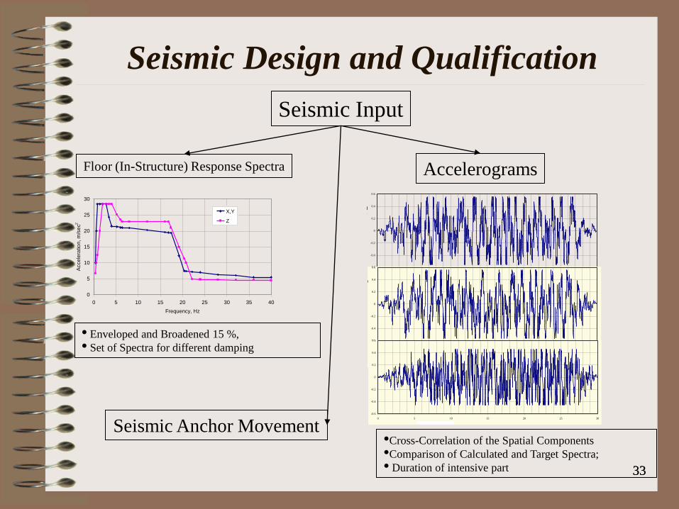
Seismic Input
Floor (In-Structure) Response Spectra Accelerograms
• Enveloped and Broadened 15 %,
• Set of Spectra for different damping
0
5
10
15
20
25
30
0 5 10 15 20 25 30 35 40
Frequency, Hz
Acce
lera
tion
, m
/se
c2
X,Y
Z
X-Direction
-0.6
-0.4
-0.2
0
0.2
0.4
0.6
0 5 10 15 20 25 30
Time, Sec
Accele
rati
on
, g
Y-Direction
-0.6
-0.4
-0.2
0
0.2
0.4
0.6
0 5 10 15 20 25 30
Time, SecA
ccele
rati
on
, g
Z-Direction
-0.6
-0.4
-0.2
0
0.2
0.4
0.6
0 5 10 15 20 25 30
Time, Sec
Accele
ra
tion
, g
•Cross-Correlation of the Spatial Components
•Comparison of Calculated and Target Spectra;
• Duration of intensive part
Seismic Anchor Movement
33 33
Seismic Design and Qualification
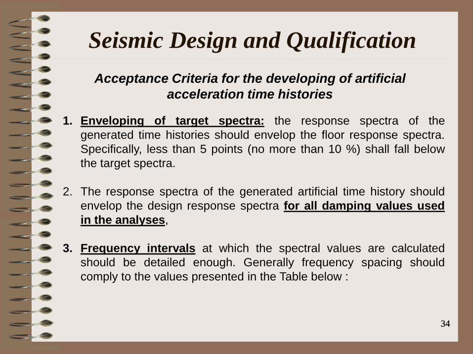
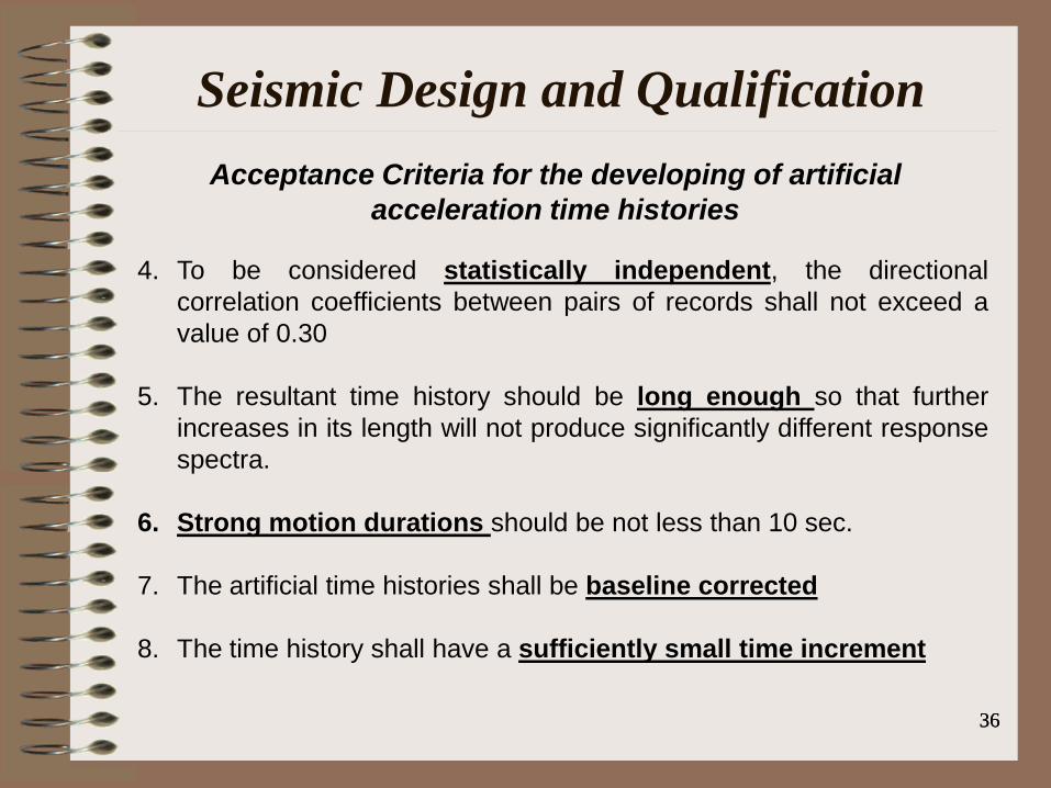
Acceptance Criteria for the developing of artificial
acceleration time histories
Seismic Design and Qualification
1. Enveloping of target spectra: the response spectra of the
generated time histories should envelop the floor response spectra.
Specifically, less than 5 points (no more than 10 %) shall fall below
the target spectra.
2. The response spectra of the generated artificial time history should
envelop the design response spectra for all damping values used
in the analyses,
3. Frequency intervals at which the spectral values are calculated
should be detailed enough. Generally frequency spacing should
comply to the values presented in the Table below :
34 34

Acceptance Criteria for the developing of artificial
acceleration time histories
Seismic Design and Qualification
35
Frequency intervals for calculation of response spectrum
Frequency range (Hz) Increment (Hz)
0,2 - 3 0,10
3,- 3,6 0,15
3,6 - 5 0,20
5 - 8 0,25
8 - 15 0,50
15 - 18 1
18 - 22 2
22 - 40 3
35
Acceptance Criteria for the developing of artificial
acceleration time histories
Seismic Design and Qualification
36
4. To be considered statistically independent, the directional
correlation coefficients between pairs of records shall not exceed a
value of 0.30
5. The resultant time history should be long enough so that further
increases in its length will not produce significantly different response
spectra.
6. Strong motion durations should be not less than 10 sec.
7. The artificial time histories shall be baseline corrected
8. The time history shall have a sufficiently small time increment
36

Acceptance Criteria for the developing of artificial
acceleration time histories
Seismic Design and Qualification
37
References:
European utility requirements for LWR Nuclear Power, Volume 2
"Generic Nuclear Island Requirements", Appendix A "Method of Seismic
Analysis"
ASCE/SEI 43-05, Seismic Design Criteria for Structures, Systems, and
Components in Nuclear Facilities
ASME BPVC, Appendix N "Dynamic Analysis Methods"
ASCE 4-98. "Seismic Analysis of Safety-Related Nuclear Structures
and Commentary."
NUREG-0800. “Standard Review Plan. Paragraph 3.7.1. Seismic
Design Parameters.”
IEEE Std 344-2004. ”IEEE Recommended Practice for Seismic
Qualification of Class 1E Equipment for Nuclear Power Generating
Stations
37
Seismic Design and Qualification
38 38
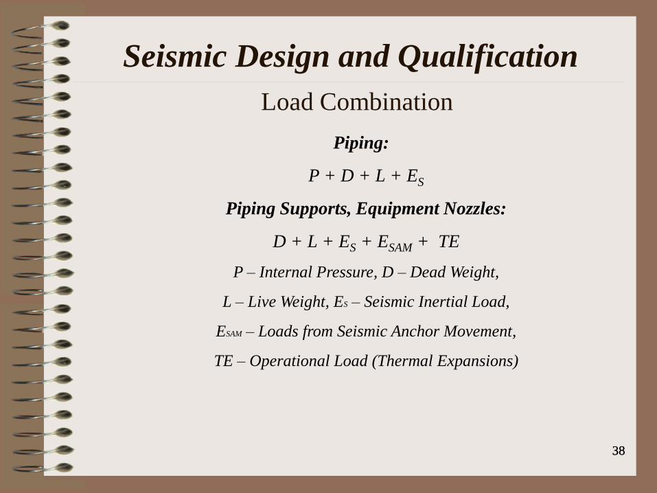
Load Combination
Piping:
P + D + L + ES
Piping Supports, Equipment Nozzles:
D + L + ES + ESAM + TE
P – Internal Pressure, D – Dead Weight,
L – Live Weight, ES – Seismic Inertial Load,
ESAM – Loads from Seismic Anchor Movement,
TE – Operational Load (Thermal Expansions)

Seismic Design and Qualification
39 39
Conditions that caused piping failures (Rules of Thumb):
Unacceptable anchor motion;
Rigidly tied branch lines and flexible header;
Poor Horizontal restraining;
Too long valve operators;
Poor Material conditions;
Poor Construction quality;
Undersized pipe support members;
Significant Interactions

Seismic Design and Qualification
40 40
(ASME B31E “Standard for the Seismic Design and Retrofit
of Above-Ground Piping Systems”)

Seismic Design and Qualification
41 41
(ASME B31E “Standard for the Seismic Design and Retrofit
of Above-Ground Piping Systems”)
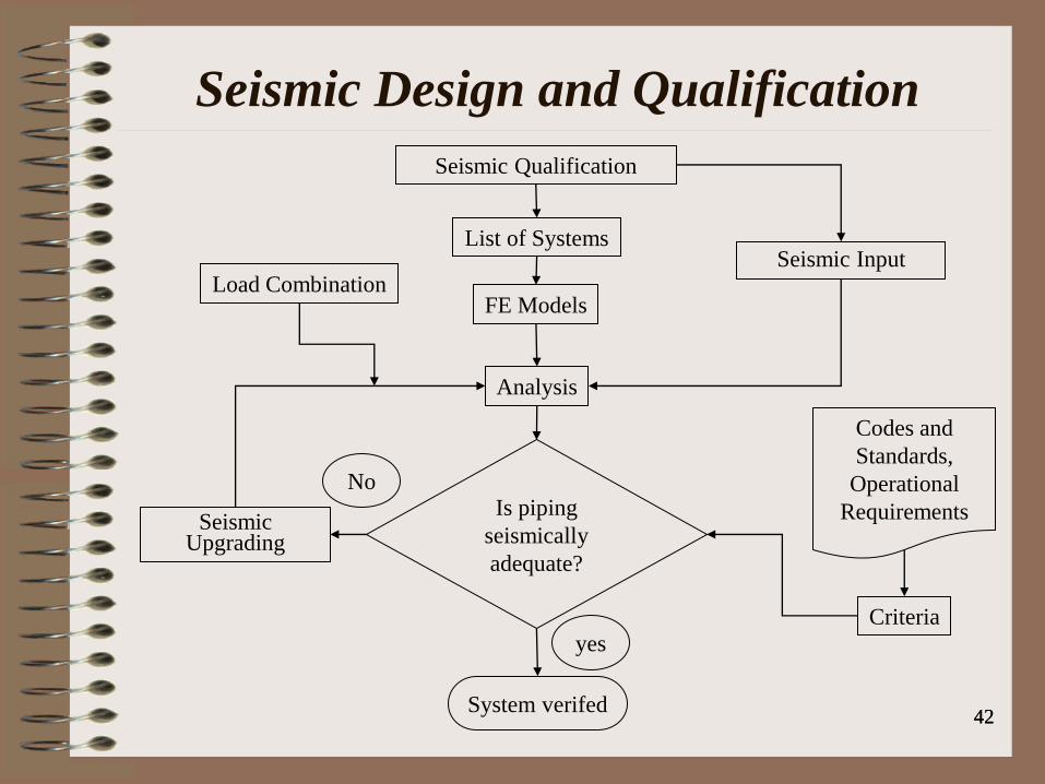
Seismic Input
Seismic Qualification
List of Systems
FE Models
Analysis
Criteria
Is piping
seismically
adequate?
Seismic Upgrading
Codes and
Standards,
Operational
Requirements
System verifed
yes
No
Load Combination
42 42
Seismic Design and Qualification
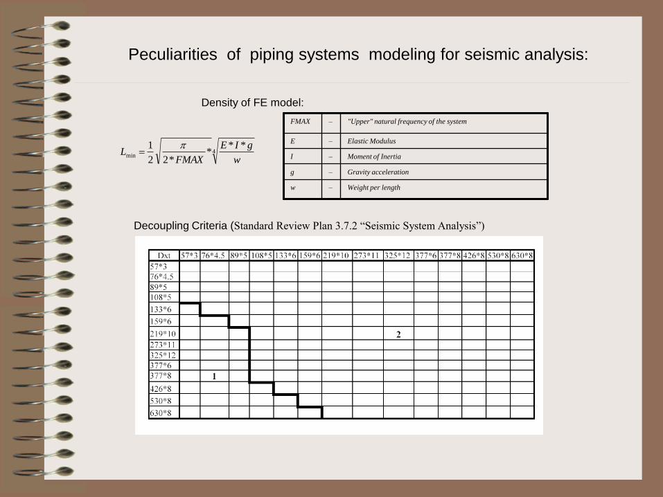
4min
***
*22
1
w
gIE
FMAXL
FMAX – "Upper" natural frequency of the system
E – Elastic Modulus
I – Moment of Inertia
g – Gravity acceleration
w – Weight per length
Peculiarities of piping systems modeling for seismic analysis:
Density of FE model:
Decoupling Criteria (Standard Review Plan 3.7.2 “Seismic System Analysis”)

Service Limits
• ASME BPVC establishes four Levels of Service Limits Loading for each
component or support. These Service Limits may be designated in the
Design Specification and defined as different Levels (Levels A, B, C and D).
• The NCA-2142.4 gives the following definition of these Service Limits:
• Level D Service Limit. Level D Service limits are those sets of limits which
must be satisfied for all Level D Service loading identified in the Design
Specification for which these Service Limits are designated. These sets of
limits permit gross general deformations with some consequent loss of
dimensional stability and damage requiring repair, which may require
removal of the component from service. Therefore the selection of this limits
shall be reviewed by the Owner for compatibility with established system
safety criteria (NCA-2141).

Definition of Seismic Loads
• The ASME BPVC has a several subsections especially oriented for
seismic analysis and design. Among them one of the most important
is the Appendix N “Dynamic Analysis Methods”, which contains the
article “Seismic analysis”. In this article there are the following
items:
• N-1210 - “Earthquake description“. This article contains the detailed
description and recommendations about applied input seismic
excitation in terms of the Response Spectrum and Time History as
well.
• N-1220 - “Methods of dynamic analysis“. This chapter gives a full
range of dynamic modeling and analysis technique description such
like THA and Response Spectrum Method.
• N-1230 - "Damping”. The recommended damping values for
different types of constructions are presented in this article. Also the
various methods of incorporating the damping in structural dynamics
are given.

DAMPING VALUES FOR PIPES ACCORDING TO
ASME BPVC
Pipe Level B Level D Case N-411-1
OBE SSE 0 - 10 Hz 10 - 20 Hz > 20 Hz
D > 305mm 0.02 0.03 0.05 0.05 - 0.02 0.02
D < 305mm 0.01 0.02 0.05 0.05 - 0.02 0.02
ASME BPVC provides the different values of damping which are depended from
the seismic excitation level and pipe output diameter. In the Japan JEAG 4601 the
damping values depends on type of piping, number of supports and insulation
parameter and vary from 0,5 to 2,5%.
Table demonstrates ASME BPVC values and contains the damping ratio values
recommended for seismic analysis.
Application of the Case N-411-1 may significantly reduce the seismic response up to
30-35 % in comparison with values originally used in ASME BPVC.
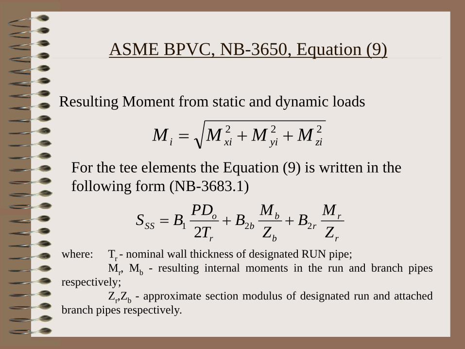
ASME BPVC, NB-3650, Equation (9)
Resulting Moment from static and dynamic loads
222
ziyixii MMMM
For the tee elements the Equation (9) is written in the
following form (NB-3683.1)
r
rr
b
bb
r
oSS
Z
MB
Z
MB
T
PDBS 221
2
where: Tr - nominal wall thickness of designated RUN pipe;
Mr, Mb - resulting internal moments in the run and branch pipes
respectively;
Zr,Zb - approximate section modulus of designated run and attached
branch pipes respectively.

For straight pipes: B1 = 0.5 and B2 = 1.0;
For curved pipes: B1 = -0.1 + 0.4h , if 0.0 < B1 < 0.5,
B2 = if B2 > 1.0;
For tee elements B2b and B2r are defined in accordance with
NB-3683.8 and NB-3683.9 /3/.
Stress indices B1 and B2
(defined by the table NB-3681(a)-1)
3
2
30.1 h

49
ASME BPVC (NB/NC/ND-3600)
The conditions of eq. (9) of NB-3652 shall be met using Service Level D
coincident pressure P and moment Mi, which results in the maximum
calculated stress. The allowable stress to be used for this condition is 3.0
Sm, but not greater than 2.0 Sy.

50
ASME BPVC (NB/NC/ND-3600)

51
ASME BPVC (NB/NC/ND-3600)
An alternative to NB-3656(a):
piping fabricated from ductile material (P-1 – P-9)
D/tn≤ 40
The sustained stresses due to weight are limited:
The stress due to weight and inertial loading due to reversing dynamic
loads:
Seismic anchor motion:
PIPING ANALYSIS SOFTWARE
ME-21,
ADLPIPE,
NUPIPE,
PIPESTRESS,
SYSPIPE
CAESARII,
AUTOPIPE,
TRIFLEX,
SIMFLEX,
CAEPIPE,
dPIPE

Seismic Restraints
1. Sway Braces
2. Snubbers
2а. Hydraulic 2б. Mechanical

Seismic Restraints
3. Axial dampers (absorbers)
3а. Hydraulic 3б. Elastic-plastic
4. Viscous Dampers

General requirements for seismic restraints
Damping ability for any dynamic effects (vibration, shock,
seismic, etc.);
Long service life without maintenance;
Resistance to the heat and radiation;
A small reaction force acting on the piping during thermal
expansion;
The absence of lag response under dynamic loading;
The ability for overload without loss of functionality and
mechanical properties;
Ability to control performance;
The low cost of manufacture and operation

Description of High Viscous Damper
High damping in the device is a result of deformation of an
extremely high viscous liquid that is located in the space
between damper’s piston and housing.
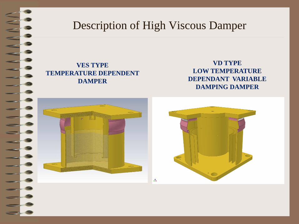
VES TYPE
TEMPERATURE DEPENDENT
DAMPER
VD TYPE
LOW TEMPERATURE
DEPENDANT VARIABLE
DAMPING DAMPER
Description of High Viscous Damper

Installation of Dampers

Installation of Dampers
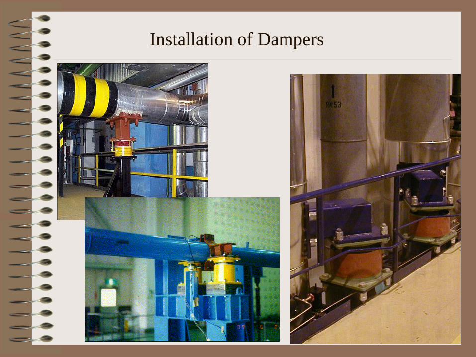
Installation of Dampers
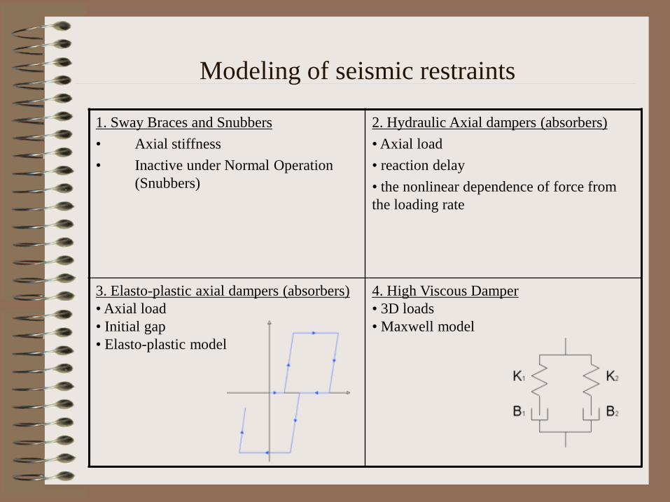
Modeling of seismic restraints
1. Sway Braces and Snubbers
• Axial stiffness
• Inactive under Normal Operation
(Snubbers)
2. Hydraulic Axial dampers (absorbers)
• Axial load
• reaction delay
• the nonlinear dependence of force from
the loading rate
3. Elasto-plastic axial dampers (absorbers)
• Axial load
• Initial gap
• Elasto-plastic model
4. High Viscous Damper
• 3D loads
• Maxwell model
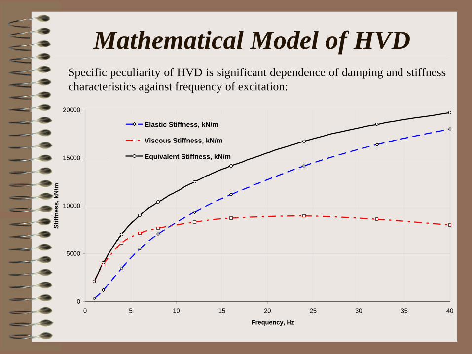
Mathematical Model of HVD Specific peculiarity of HVD is significant dependence of damping and stiffness
characteristics against frequency of excitation:
0
5000
10000
15000
20000
0 5 10 15 20 25 30 35 40
Frequency, Hz
Sti
ffn
ess,
kN
/m
Elastic Stiffness, kN/m
Viscous Stiffness, kN/m
Equivalent Stiffness, kN/m

Mathematical Model of HVD
Features of Maxwell Model for HVD :
the reaction of HVD at the low frequency loading range is considered as a viscous and may be described by an expression: R = -B*v, where R – reaction force, v –velocity of a piston relatively to the housing, B – damping resistance;
for the high frequency range the damper's reaction shows essentially elastic character and may be described as: R = -K*x, where x – relative displacement "piston-hosing", K – stiffness ratio
K
B

Mathematical Model of HVD
0 = K/B - characteristic frequency
R = x0*Ce*sin(*t) + x0*Cv*cos(*t)
R = x0*Cs*sin(*t + ); tg() = Cv/Ce; Cs = (Ce2 + Cv
2)1/2
Ce = K*(/0)2/(1 + (/0)
2); Ce = K*(/0) /(1 + (/0)
2)
Phase Angle Maxwell Model Characteristics

Mathematical Model of HVD
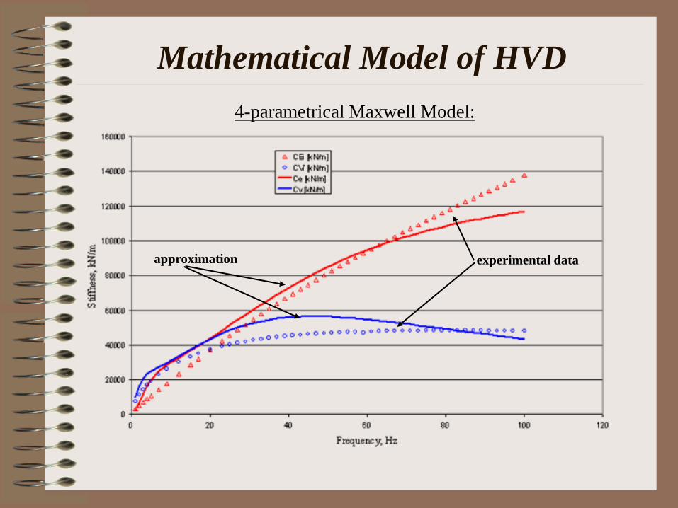
4-parametrical Maxwell Model:
Ce = K1*(/1)2/(1 + (/1)
2) + K2*(/2)2/(1 + (/2)
2)
Cv = K1*(/1)/(1 + (/1)2) + K2*(/2)/(1 + (/2)
2)
1 = K1/B1
2 = K2/B2
characteristic frequencies for first and second
Maxwell chains
Mathematical Model of HVD
4-parametrical Maxwell Model:
experimental data approximation
Simplified Model of HVD
4-parametrical Maxwell model is suitable for realization in the
frame of the Time History Analysis (THA);
Maxwell model of HVD is realized only in a few software
packages: ROHR2 and dPIPE;
most commercially available piping software packages still use
for dynamic restraints only "snubber" model;
the benefits of "snubber“ modeling is a possibility to implement
conventional response spectrum (RSM) method for a solution;
such approach neglects damping introduced by HVD in piping
system;
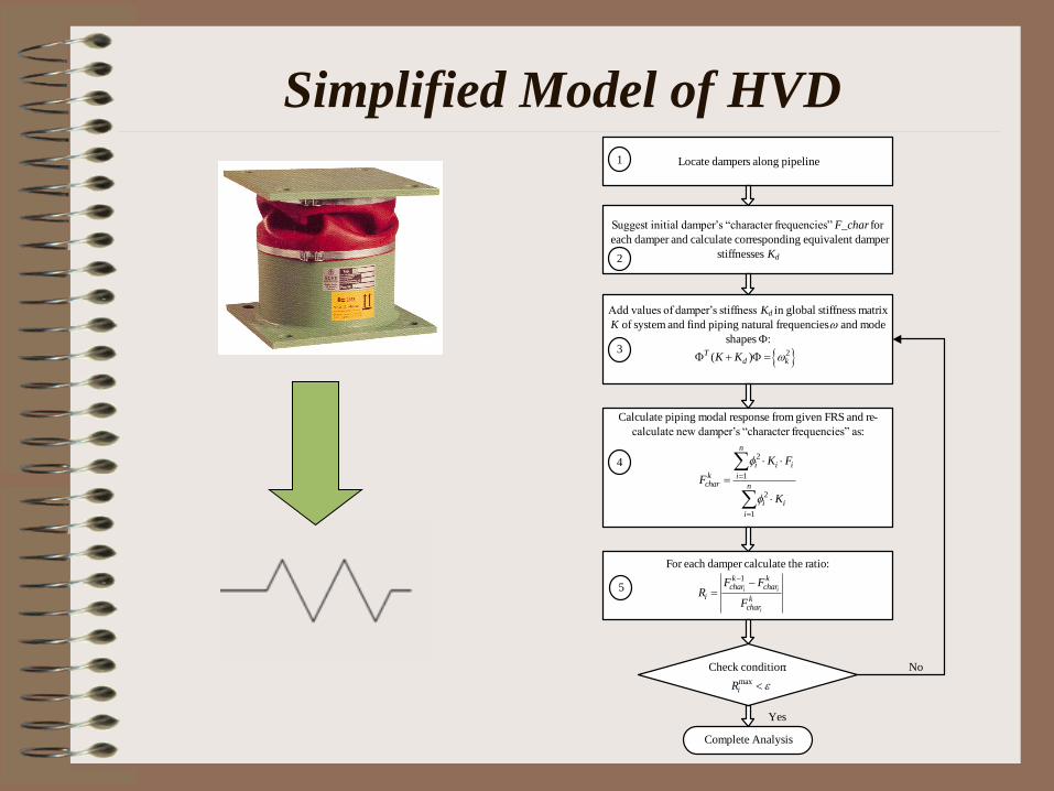
Simplified Model of HVD Locate dampers along pipeline
Add values of damper’s stiffness Kd in global stiffness matrix
K of system and find piping natural frequencies and mode
shapes F:
Suggest initial damper’s “character frequencies” F_char for
each damper and calculate corresponding equivalent damper
stiffnesses Kd2
1
3
Complete Analysis
Yes
No
2( )Td kK K F F
Calculate piping modal response from given FRS and re-
calculate new damper’s “character frequencies” as:
42
1
2
1
n
i i i
k ichar n
i i
i
K F
F
K
For each damper calculate the ratio:
1
i i
i
k kchar char
i kchar
F FR
F
Check condition:maxiR
5
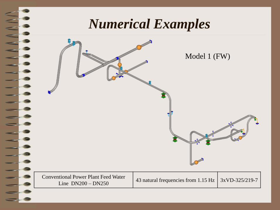
Numerical Examples
Conventional Power Plant Feed Water
Line DN200 – DN250 43 natural frequencies from 1.15 Hz 3xVD-325/219-7
Model 1 (FW)

Numerical Examples
Conventional Power Plant High Pressure and
Temperature Steam line (from DN150 –
DN400)
142 natural frequencies
from 0.64 Hz
14 HVD: from VD-159/76-7
to VD-426/219-15
Model 2 (HPP)

Numerical Examples
Industrial Piping (DN400 – DN800) 58 natural frequencies
from 1.94 Hz
7 HVD: from VD-325/219-7 to
VD-630/426-15
Model 3 (IS)

Numerical Examples
Nuclear Safety Related Piping
(DN150 – DN300)
93 natural frequencies
from 0.85 Hz
3xVD-325/219-7 +
11xVD-426/325-7
Model 4 (JND)

Numerical Examples
Nuclear Class 1 Piping (Pressurizer
system), DN100
40 natural frequencies
from 0.75 Hz 1xVD-219/108-7
Model 5 (KO)

0
0.5
1
1.5
2
2.5
3
FW HPP IS JND KO
Piping Models
Rati
o =
RS
M / T
HA
mean
max
min
mean-sigma
Displacements
Statistical processing of analysis results

Statistical processing of analysis results
Moments
0
0.5
1
1.5
2
2.5
FW HPP IS JND KO
Piping Models
Ra
tio
= R
SM
/ T
HA
mean
max
min
mean-sigma
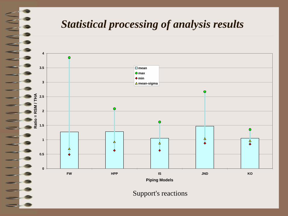
Statistical processing of analysis results
Support's reactions
0
0.5
1
1.5
2
2.5
3
3.5
4
FW HPP IS JND KO
Piping Models
Rati
o =
RS
M / T
HA
mean
max
min
mean-sigma
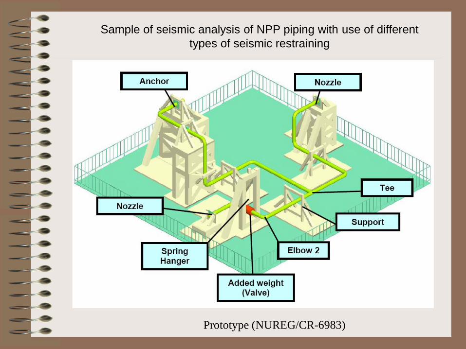
Sample of seismic analysis of NPP piping with use of different
types of seismic restraining
Prototype (NUREG/CR-6983)

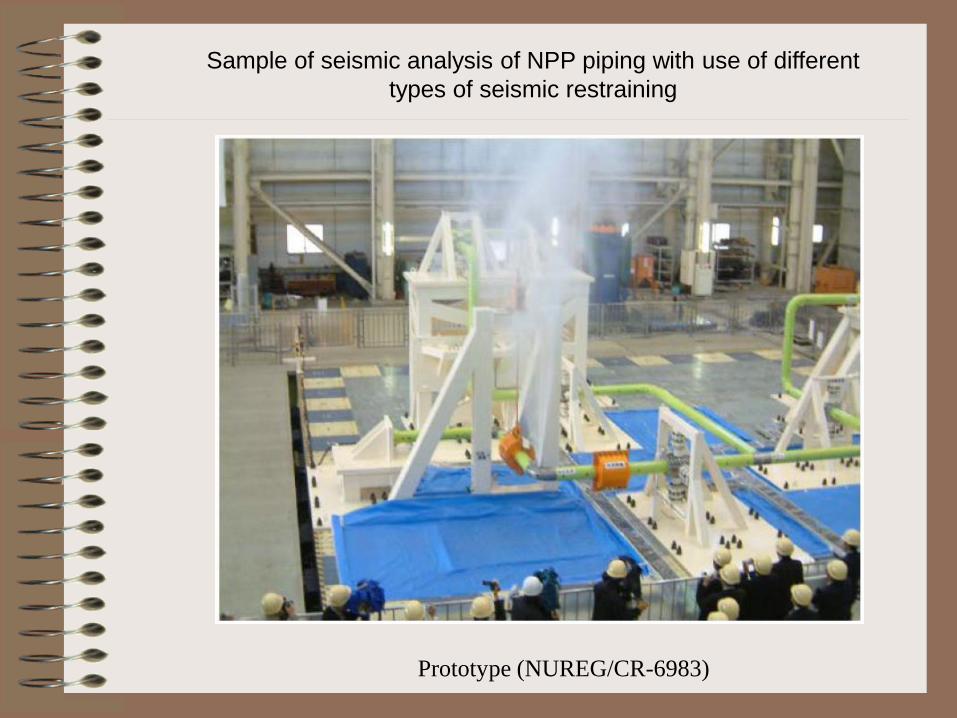
Sample of seismic analysis of NPP piping with use of different
types of seismic restraining
Prototype (NUREG/CR-6983)
Sample of seismic analysis of NPP piping with use of different
types of seismic restraining
Prototype (NUREG/CR-6983)

Sample of seismic analysis of NPP piping with use of different
types of seismic restraining
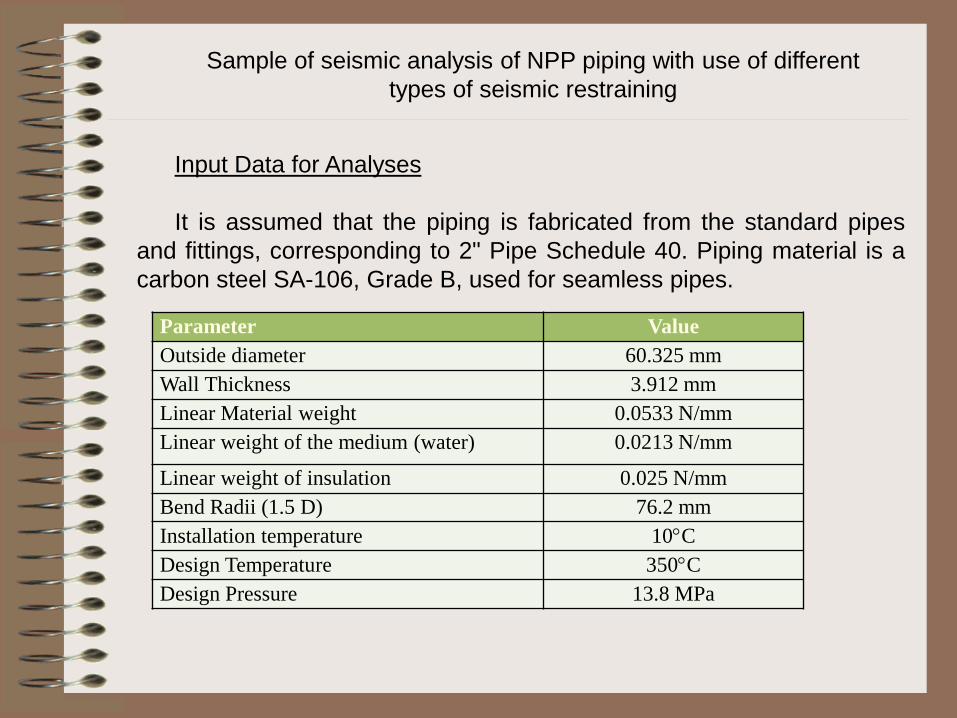
Input Data for Analyses
It is assumed that the piping is fabricated from the standard pipes
and fittings, corresponding to 2" Pipe Schedule 40. Piping material is a
carbon steel SA-106, Grade B, used for seamless pipes.
Sample of seismic analysis of NPP piping with use of different
types of seismic restraining
Parameter Value
Outside diameter 60.325 mm
Wall Thickness 3.912 mm
Linear Material weight 0.0533 N/mm
Linear weight of the medium (water) 0.0213 N/mm
Linear weight of insulation 0.025 N/mm
Bend Radii (1.5 D) 76.2 mm
Installation temperature 10C
Design Temperature 350C
Design Pressure 13.8 MPa

Input Data for Analysis
T, С (mm/mm/С)*10-5 T, С E, MPa T,С Sy, MPa T,С St, MPa
21 1.15 21 202700 -29 241 -29 414
38 1.17 93 198600 38 241 38 414
66 1.19 149 195100 66 227 93 414
93 1.21 204 192400 93 221 149 414
121 1.22 260 188200 121 217 204 414
149 1.24 316 182700 149 214 260 414
177 1.26 371 175800 204 206 316 414
204 1.28 260 197 343 414
232 1.3 316 185 371 414
260 1.31 343 179
288 1.31 371 173
316 1.33
343 1.35
371 1.37
Sample of seismic analysis of NPP piping with use of different
types of seismic restraining

Seismic Input
Seismic input was defined in the form of the generic broadband floor
response spectrum. The excitation is considered as uniform for each of the
spatial directions. For purposes of the actual evaluation three levels of
seismic excitation are considered: low, moderate and high. Each level of
excitation was obtained by multiplying the spectrum acceleration on the
coefficients 1, 2 and 3, respectively.
Three artificial accelerograms were generated for the use in the frame of
Time History Analysis. Duration of each record is 20 sec, time step is 0.01
sec.
For an equivalent static method a seismic input was defined in the form
of the distributed inertial load applied for each spatial direction. Load vector
was calculated as a product of peak spectrum acceleration amplified on the
coefficient of 1.5 times the piping mass. Then, combined seismic response
was obtained by SRSS rule.
Sample of seismic analysis of NPP piping with use of different
types of seismic restraining
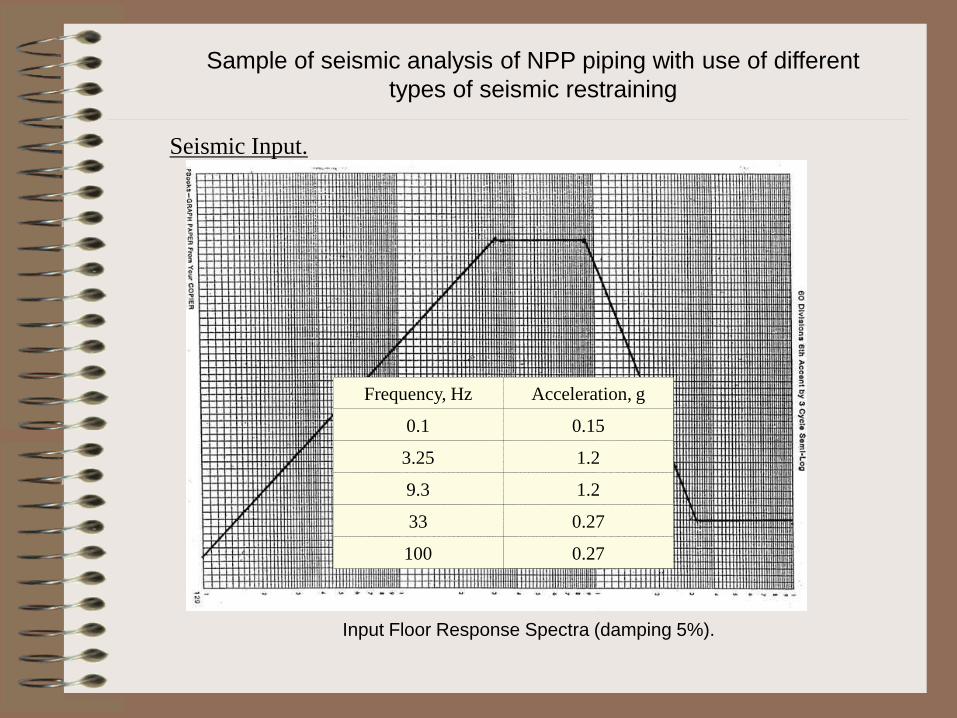
Seismic Input.
Input Floor Response Spectra (damping 5%).
Frequency, Hz Acceleration, g
0.1 0.15
3.25 1.2
9.3 1.2
33 0.27
100 0.27
Sample of seismic analysis of NPP piping with use of different
types of seismic restraining

Seismic Input
-0.3
-0.2
-0.1
0
0.1
0.2
0.3
0 2 4 6 8 10 12 14 16 18 20
Time, sec
Acce
lerati
on, g
-0.3
-0.2
-0.1
0
0.1
0.2
0.3
0 2 4 6 8 10 12 14 16 18 20
Time, sec
Accel
eratio
n, g
-0.3
-0.2
-0.1
0
0.1
0.2
0.3
0 2 4 6 8 10 12 14 16 18 20
Time, sec
Accel
eration
, g
X
Y
Z
Sample of seismic analysis of NPP piping with use of different
types of seismic restraining
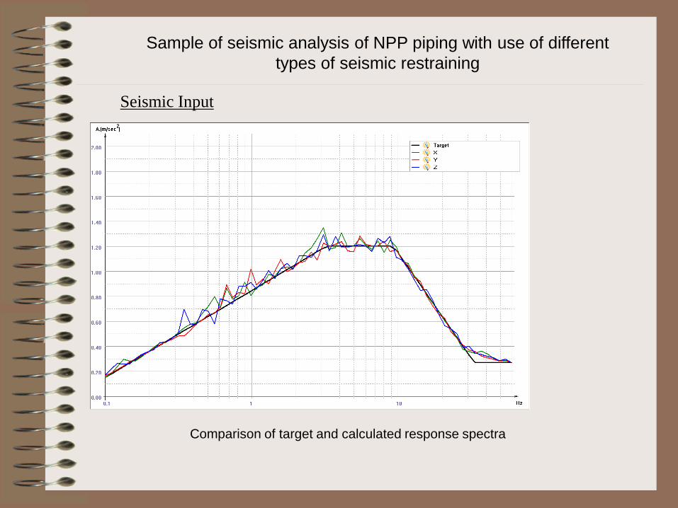
Seismic Input
Comparison of target and calculated response spectra
Sample of seismic analysis of NPP piping with use of different
types of seismic restraining
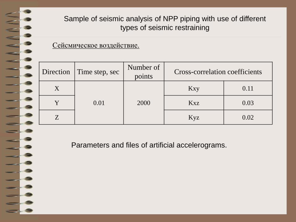
Direction Time step, sec Number of
points Cross-correlation coefficients
X
0.01 2000
Kxy 0.11
Y Kxz 0.03
Z Kyz 0.02
Сейсмическое воздействие.
Parameters and files of artificial accelerograms.
Sample of seismic analysis of NPP piping with use of different
types of seismic restraining

Static Analysis.
On the first stage of analysis weight supports were located along the line. On the horizontal parts of piping
a sliding supports with friction coefficient 0.3 were placed. On the vertical pipe sections a spring hangers
were installed to carry weight load and compensate thermal expansion as well. The distance between
weight supports was defined according to the recommendations of revised Table NF-3611-1 and was
assessed to be equal 6 m.:
Sample of seismic analysis of NPP piping with use of different
types of seismic restraining
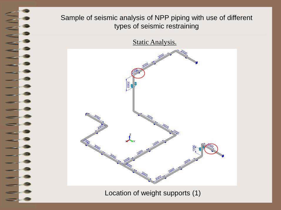
Location of weight supports (1)
Sample of seismic analysis of NPP piping with use of different
types of seismic restraining
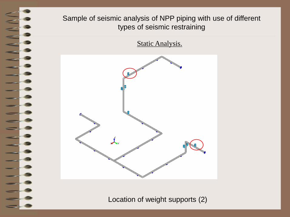
Static Analysis.
Sample of seismic analysis of NPP piping with use of different
types of seismic restraining
Location of weight supports (2)
Static Analysis.
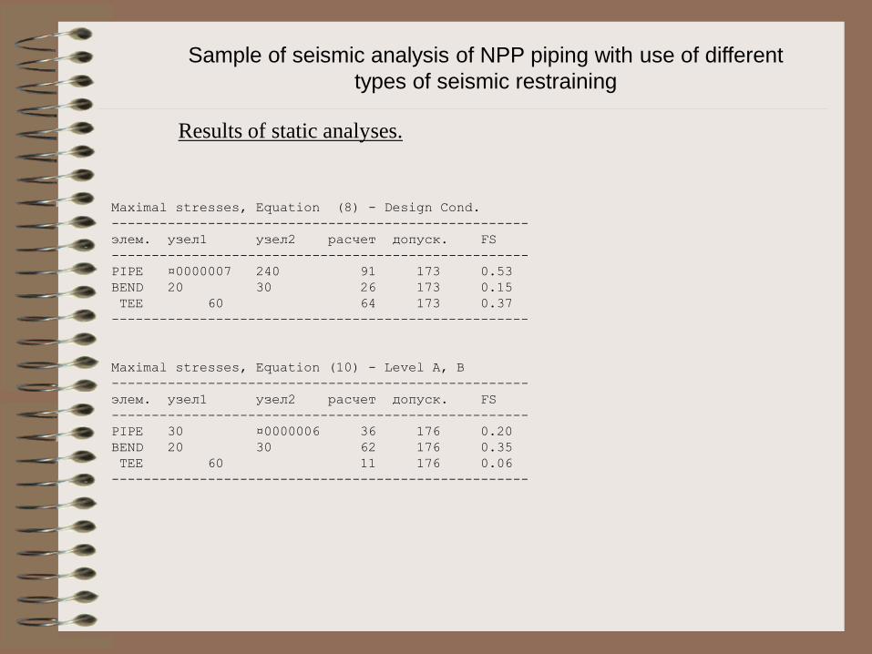
Results of static analyses.
Maximal stresses, Equation (8) - Design Cond.
----------------------------------------------------
элем. узел1 узел2 расчет допуск. FS
----------------------------------------------------
PIPE ¤0000007 240 91 173 0.53
BEND 20 30 26 173 0.15
TEE 60 64 173 0.37
----------------------------------------------------
Maximal stresses, Equation (10) - Level A, B
----------------------------------------------------
элем. узел1 узел2 расчет допуск. FS
----------------------------------------------------
PIPE 30 ¤0000006 36 176 0.20
BEND 20 30 62 176 0.35
TEE 60 11 176 0.06
----------------------------------------------------
Sample of seismic analysis of NPP piping with use of different
types of seismic restraining

Thermal Expansion
Sample of seismic analysis of NPP piping with use of different
types of seismic restraining
Results of static analyses.

Sample of seismic analysis of NPP piping with use of different
types of seismic restraining
Three methods were considered for the seismic analysis of the considered
piping:
equivalent static load analysis (ESLA): seismic load is considered as a
distributed inertial load and calculated by multiplying the mass of the pipe
at the maximum spectral peak acceleration, multiplied by a factor of 1.5.
The resulting load vector was applied to the system in three spatial
directions, the overall response was obtained using the SRSS combination
rule;
response spectrum method (RSM): seismic response of the system is
based on the modal analysis. Seismic input in that case is defined in terms
of floor response spectra. Intermodal and spatial combination of seismic
loads is realized with use of SRSS rule;
time history analysis (THA): seismic response of the system is based on
the modal integration of equations of motion of the piping system. Seismic
input is defined as a three-component accelerograms. Maximum seismic
response of the pipe is calculated at each integration step.
Sample of seismic analysis of NPP piping with use of different
types of seismic restraining
To achieve seismic resistance the considered piping was restrained by
means of additional supports. Analyses were performed within each of the
three above methods. Three variants of restraints were considered:
1. "static" restraints, such as rod hangers and rigid struts or guides: these
linear restraints limit piping movements in one direction. They are
active under static as well as dynamic loads. In the frame of all above
methods these restraints were modeled as one-dimensional rigid
elements.
2. hydraulic snubbers (shock absorbers) selected from LISEGA
catalogue. Snubbers are also one-directional restraints, but they are
active only for dynamic loads, but not for static loads. Modeling of
snubbers is realized by means of the spring elements with stiffness
ratio taken from the Catalogue
3. high viscous dampers (HVD) manufactured by GERB company.
Sample of seismic analysis of NPP piping with use of different
types of seismic restraining
The following seismic criteria were considered within performed analyses:
check of stresses in piping elements according to the equation (9) , NC-
3653.1 taking into account allowable values defined for Service Level D
(NC-3655);
check of support's reactions under normal operation conditions plus
seismic loads. For spring hanger supports this criterion is defined as
follow:
|PSSE| + |PNOL| < PMAX
(prevention of the full compression of the spring)

Sample of seismic analysis of NPP piping with use of different
types of seismic restraining
Method:
No seismic restraints Type of restraining
"Static" supports1) Snubbers Dampers
ESLA RSM THA ESLA RSM THA ESLA RSM THA ESLA RSM THA
exci
tati
on
Low 4.7 1.78 2.38 0.88 0.97 0.98 0.75 0.96 0.76 0.97 0.78 0.9
Moderate 9.37 3.55 4.46 0.9 0.72 0.82 0.95 0.76 0.94 0.69 0.58 0.73
High 14.03 5.31 6.55 0.84 0.99 0.96 0.92 0.92 0.99 0.93 0.85 0.9
Summary of performed analyses. Demand to Capacity (D/C) Ratio

Sample of seismic analysis of NPP piping with use of different
types of seismic restraining
Method:
Type of restraining
"Static" supports1) Snubbers Dampers
ESLA RSM THA ESLA RSM THA ESLA RSM THA
exci
tati
on
Low 9 6 6 9 5 7 4 4 4
Moderate 13 10 10 12 11 10 6 6 6
High 15 10 12 17 15 11 6 6 7
Number of additional supports required to achieve piping seismic resistance.
Top Related