


Languages
Pages
Legal


International Journal of Emerging Technology and Advanced Engineering
Website: www.ijetae.com (ISSN 2250-2459, ISO 9001:2008 Certified Journal, Volume 2, Issue 12, December 2012)
34
Sedimentation Evaluation at Water Intake Gate of Grati
PLTGU Jetty Blockade Dwi Priyantoro
1, Aniek Masrevaniah
2, Seto Sugianto Sugianto Prabowo Rahardjo
3
1,2Department of Water Resources, Faculty of Engineering, University of Brawijaya, Malang of Indonesia
2Master Program of Water Resources, University of Brawijaya, Malang of Indonesia
Abstract- Jetty for water intake channel of PLTGU (Air
and Gas Electrical Power) basically was designed as a
construction which would minimize the problem of
sedimentation. There was very much sedimentation at Grati
PLTGU. The aim of this study was to evaluate
sedimentation problem jetty water intake channel of Grati
PLTGU and to find the dimension of jetty construction with
sediment degree was lower than the existing construction.
Location of study was at Pasuruan, East Java of Indonesia.
It was hoped to get dimension of jetty construction which
had low sediment level compared to existing construction.
Evaluation of water intake channel used the software of
SMS 10.1.8. Based on the evaluation of wave and stream,
there were 2 designs of jetty modification as follow: 1)
Modification of Jetty-I: it was straight upright designed or
with angle of 450 to the direction of east-north, jetty in the
right side was lengthened until 178 m with diameter of
curve was 150 m, jetty in the left side followed the
projection of jetty length in the right side due to the angle of
450; 2) Modification of jetty-II: it followed the design of
jetty-I but jetty in the right side was placed at the distance
of 20 m from breaking wave.
Keywords- jetty, sedimentation, water intake channel
I. INTRODUCTION
Sedimentation occurred usually from soil erosion in at
catchment area. The sedimentation level of severity was
depending on the type of soil, topography, rainfall
intensity, and vegetation cover. From an economics
perspective reservoir were assets that provided services
across a period of time. While sedimentation reduced the
storage volume, it also reduced the benefits that could be
derived from services provided by the reservoir over time
and ultimately shortened its economics life [1]. The
quantitative understanding of hydrodynamic and
sediment transport on intertidal mudflats were important
for the management of estuaries and environmental
protection [2]. The sediment transport and
hydrodynamics on the mudflats were influenced by
processes with a range of times scales due to freshwater
discharge, tides, and wind waves their interactions [3].
Nowadays, jetty was more used as coastal safety at
industry that used sea water for their need. Beside as
breaking wave utilization, jetty was also used for water
intake channel as water channel in the direction to
industry.
Therefore, the design had to be free of sedimentation.
There were many jetty constructions at Indonesia that
was used as water intake channel of industry. One of
them was Grati PLTGU (Air and Gas Electrical Power),
Pasuruan of Indonesia. Planning of jetty which was used
for water intake channel of PLTG was basically designed
as construction that would minimize the problem of
sedimentation. There was so much sedimentation at water
intake channel of Grati PLTGU. It could be seen at the
activity of operation and maintenance that was sediment
dredging in intake direction of Grati PLTGU.
Based on the problem as above, it was suspected that
the sedimentation at water intake channel of Grati
PLTGU was caused by inaccuracy in design. This design
was related to the length, width, and located angle of
construction to the direction of coming wave. Hence, it
was necessary to accurately evaluate and improve fitted
to existing condition. To know the quantity of sediment
due to the new design of jetty construction, it was needed
accurate modelling to detect the effect of design change
of jetty construction. Nowadays, updated software
modelling was SMS 10.1.8 (Surface Water Modelling
System) which could be simulated occurred
sedimentation due to construction design after changes.
II. MATERIALS AND METHODS
This research was as literature study. Data used in this
study were collected from PT Indonesia Power Unit
Bisnis Pembangkitan (UBP, Indonesian Power Unit of
Generation Business). Location was at Perak-Grati,
Wates Village, Lekok District, Pasuruan Regency, and
East Java of Indonesia. The PLTGU was located at about
30 km from Pasuruan City and it was included Perak
PLTU (Air Electrical Power) at Surabaya and Grati
PLTGU (Air and Gas Electrical Power). Perak PLTU and
Grati PLTGU had a distance of ± 90 km to each other;
total of installed capacity for both of them was 864.08
MW
Jetty was a construction which was straight upright at
coast and located at both sides of estuary. This
construction was functioned for decreasing the groove
shallowing of the both sides by coastal sediment. The
usage of river estuary as sailing groove and
sedimentation at estuary could disturb the coastal traffic.

International Journal of Emerging Technology and Advanced Engineering
Website: www.ijetae.com (ISSN 2250-2459, ISO 9001:2008 Certified Journal, Volume 2, Issue 12, December 2012)
35
To accommodate this need, jetty had to be long until
the edge was outside of breaking wave [4][5]. Sediment
transport of coast was held due to long jetty and sailing
line at wave condition was not broken so that was
possible for the ship bewitch to estuary of the river. Jetty
could also be used to prevent the shallowing at estuary
due to flood control. Rivers which emptied into sandy
coast with big enough of wave often went through
estuary closing by sandy sediment. Because of the
influence of wave and wind, sandy sediment was formed
at estuary. Sediment transport along the coast was also
very influenced to the sediment forming. Sand that went
through in front of estuary would be pushed enter to
estuary by wave and then it was precipitated. The very
big sediment could cause river estuary was closed [6].
According to the function of jetty which was only for
flood control, there were some kinds of jetty due to the
dimension as follow and as presented as in Figure 1
below: [6]
a. Long Jetty:
Long jetty had the end outside of breaking wave. This
type was effective to prevent entering sediment to
estuary, but cinstruction cost was so expensive. Therefore
if the function was only for flood control, the usage of
this type was not economic unless if the area that had to
protect was very important.
b. Medium jetty:
Medium jetty had the end between the ebb of water
level and location of breaking wave. This type of jetty
was intended to hold part of sediment transport along the
coast. Groove at jetty end was still possible being occur
sandy sediment.
c. Short jetty:
Short jetty had end of structure at the ebb of water
level. The main function of the structure was to hold
being turned of river estuary and to concentrate the
current at remained groove for scratching sediment, so
that at the beginning of rainy season which flood had not
been occured, the estuary of river had been opened.
FIG. 1 SOME TYPES OF JETTY [6]
Design of jetty generally was used trapezoidal shape
as design of groin or breakwater. But it could also be
used sheet pile from steel or wood which in general it
was due to available material at borrow area. The steps
which were used for design of jetty were as follow: [7][8]
Long jetty
Dominant
wave
Line of
breaking wave
Dominant
wave
Medium jetty
Line of ebb
water
Short jetty
Line of ebb
water
Structure at bank

International Journal of Emerging Technology and Advanced Engineering
Website: www.ijetae.com (ISSN 2250-2459, ISO 9001:2008 Certified Journal, Volume 2, Issue 12, December 2012)
36
1. To analize generation of wave for determining
height and period of wave based on corrected of
wind tension factor.
2. To analyze length of fetch from topography map.
3. To analyze rose wave which gave interpretation of
wave data frequency according to the direction
group and classification of wave height in
precentage of wave number.
4. To analize data of yearly significant wave using the
method of JONSWAP
5. To analyze design wave for determining wave
height with certain return period.
6. To analyze SMS model of ADCIRC
7. To analize refraction and breaking of wave using
model of CMS-WAVE and ST-WAVE
8. To control the height of Run Up
9. Modification pattern of jetty
10. To calculate sediment using model of PTM.
III. RESULTS AND DISCUSSION
Data that were collected in this study included data of
bathymetry, wind, existing jetty design, ebb tidal,
sediment, and stream. Data of bathymetry was classified
into shallow water (until the depth of 5 m) and deep
water (the depth in the range of 2 to 20 m). In general,
base slope of coast was not steep. It could be seen when
there was ebb water that was coastal wave could reach
not less than 1 km from coastal line of normal water.
Result of bathymetry by sounding indicated that bed
coast at the location started from coastal line until the
direction of 2,500 m was not steep, that was reaching the
elevation of -2.50 m. But after that, bed slope was much
steeper.
Analysis of wave estimation used the data of wind in
the year of 2001 until 2010. This data was collected from
Juanda Station of BMKG, Surabaya which was placed at
2.8 m from sea water level. This analysis was included
wave generation due to wind and the most dominant
direction of wind in location of study. Based on historical
data, some of wind at location of study was as calm type.
Result of field measuring indicated that wind with
velocity less than 10 knot had reached 70% of
occurrences. Longer data at Juanda Station showed that
wind with velocity bigger than 15 knot, 20 knot, and 25
knot sequent were 15 hours, 7 hours, and 4 hours [7].
Blowing time at location of study caused by high wave
forming by time was 4 to 6 hours at high velocity.
Analysis was used data with wind velocity ≤ 20 knot. It
was caused by velocity less than 15 knot would produce
unlimited blowing and the possibility to form perfect
wave was so small.
Jetty construction of Grati PLTGU was made of
concrete sheet pile with length of 12 m and had
dimension of 0.40 x 1.0 m at each sheet pile. Existing
jetty was made sticking out to the north with length of
500 m. Sheet pile was at the depth of -8.5 m with bed
elevation of +0.5 m and over elevation was at +4.0 m
(included 0.5 m of pile cap). Jetty construction was
strengthened by pile cap so that the construction was not
put off from sheet pile and then the pile cap was also
strengthened with concrete pile with diameter of 0.6 m
and length of 20 m at each interval of 2 m, Existing
condition of sheet pile was presented as in Figure 2, 3,
and 4 below
.
FIG. 2 JETTY CONSTRUCTION OF GRATI PLTGU (LONG SECTION)
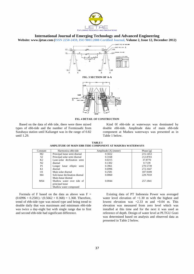
At the beginning of design, dredging was planned at
elevation of -3.1 m with variation width between 50 to
80m which was used as elevation boundary of dredging
capital. It was presented as in Figure 3 and 4 below.
International Journal of Emerging Technology and Advanced Engineering
Website: www.ijetae.com (ISSN 2250-2459, ISO 9001:2008 Certified Journal, Volume 2, Issue 12, December 2012)
37
FIG. 3 SECTION OF A-A
FIG. 4 DETAIL OF CONSTRUCTION
Based on the data of ebb tide, there were three mixed
types of ebb-tide and the number of Formizaahi from
Surabaya station until Kalianget was in the range of 0.82
until 1.29.
Kind 0f ebb-tide at waterways was dominated by
double ebb-tide. Amplitude data of main ebb-tide
component at Madura waterways was presented as in
Table 1 below.
TABLE I
AMPLITUDE OF MAIN EBB-TIDE COMPONENT AT MADURA WATERWAYS
Constant Harmonica ebb-tide Amplitude [A] (meter) Phase [g]
M2
S2 K2
N2
P1 K1
O1
M4
MS4
Principal lunar semi diurnal
Principal solar semi diurnal Lune-solar declination semi
diurnal
Longer lunar elliptic semi diurnal
Main solar diurnal
Soli-lunar declination diurnal Main-lunar diurnal
Shallow water over tide of
principal lunar Shallow water compound
0.5652
0.3168 0.0215
0.1302
0.3961 0.6996
0.2581
0.0060
0.0044
215.1453
212.8703 37.8770
0.7139
270.5739 272.1647
187.9189
229.7010
257.1841
Formula of F based on the data as above was F =
(0.6996 + 0.2581) / (0.5662 + 0.368) = 1.368. Therefore,
trend of ebb-tide type was mixed type and being trend to
double daily that was maximum and minimum ebb-tide
was twice a day-night but with single range due to first
and second ebb-tide had significant difference.
Existing data of PT Indonesia Power was averaged
water level elevation of +1.30 m with the highest and
lowest elevation was +2.33 m and +0.04 m. This
elevation was measured from zero level which was
installed at this time and for the next it was used as
reference of depth. Design of water level at PLTGU Grati
was determined based on analysis and observed data as
presented in Table 2 below.

International Journal of Emerging Technology and Advanced Engineering
Website: www.ijetae.com (ISSN 2250-2459, ISO 9001:2008 Certified Journal, Volume 2, Issue 12, December 2012)
38
TABLE II
EVALUATION OF DESIGN WATER LEVEL AT GRATI PLTGU
No Water level Symbol Evaluation (m)
1.
2. 3.
4.
5.
Highest high Water Level
Mean higher Water Level Mean Sea Water Level
Mean lowest Low Water Level
Lowest Low Water Level
HHWL
MHHWL MSL
MLLWL
LLWL
+ 3.70
+ 3.15 + 1.30
- 0.55
- 1.10
Observed data of sediment were included suspension
and bed load. Based on the type of composited bed
material of waterways, coastal area surrounded location
of research was dominated by soft bed material, silt, and
clay with sand content of about 10%. Laboratory of Grati
PLTGU used 30 samples of average bed material at
reclamation area which was distributed at the depth of -
1.00 to 4.00 m and size of average bed material sequent
for D35, D50, D65, and D80 was 0.029 mm, 0.038 mm,
0.049 mm, and 0.065 mm. Depth of soft land layer
reached ± 10 m to ± 1 km from coastal line, and reached
±20 m at ± 1,5 km from coastal line. Figure 5 presented
field sample at position of S1 and S30.
Velocity of stream surrounded Wates coast was in the
range of 0.10 m/s to 0.33 m/s with dominant direction to
east-west and it was about 1350. The pattern of stream
velocity which strongly blew was during 6 hours that was
at 12.00 am to 09.00 pm and it was weak at the next
hours. It indicated condition of current was influenced by
ebb-tide. In the other hand, it was said that dominant
direction of current was west and east, and big current
had trend moving to the west direction. Waterways at
surrounded of water coast was in variety which indicated
as turbulent waterways Table 3 described the current
velocity at surrounded location of study.
TABLE III
CURRENT VELOCITY AT SURROUNDED LOCATION OF STUDY
Section/ Point Velocity
m/s
Direction of
current
Location
X Y
A 0.10 NE 772,430 9,156,055
B 0.15 E 724,014 9,156,228
C 0.15 SE 722,506 9,155,308
D 0.20 W 723,018 9,155,410
E 0.15 W 723,943 9,155,708
G 0,05 SE 923,929 9,155,233
FIG. 5 LOCATION OF SAMPLE
Analysis of effective fetch
Length of effective fetch was analysed for 8 directions
of wind and it was measured from observed point with
interval of 50 and measuring number for each direction
was included the measuring at influenced area of fetch
(22,5o in the same direction of time needle and 22,5
o in
the opposite direction of time needle). Based on the
analysis, the effective fetch at Grati PLTGU was with
wind direction of north, north-east, south-west, west, and
south-east. Table 4 presented shaped fetch at every
direction.

International Journal of Emerging Technology and Advanced Engineering
Website: www.ijetae.com (ISSN 2250-2459, ISO 9001:2008 Certified Journal, Volume 2, Issue 12, December 2012)
39
TABLE IV
RECAPITULATION ON ANALYSIS OF EFFECTIVE FETCH
Direction Feff (km)
North U 50.207
North-east TL 92.921
South-west BL 39.929
West B 24.082
East T 108.654
Wave generation by wind
Wave forming at deep water waves was analysed
using spectrum formula of JONSWAP. This estimation
procedure was for non fully developed sea, either for
fetch limited condition or duration limited condition, but
for wave there was fully developed sea.
Distribution of wind direction and wave height
Data of wind velocity during 10 years (from 2001 to
2010) was classified into 9 classes with interval of 2 m/s
based on the direction of wind. Then it was classified into
the percentage of occurrence for every direction during
the 10 years. After that, it was drawn as wind rose.
Distribution of wind direction was analysed using
software of WRPLOT View in the version of 6.5.1 for
helping to determine and draw the curve of rose wave at
Grati PLTGU. Figure 6 presented wind rose of Grati
PLTGU from the year of 2001 to 2010 and Figure 7
presented wave rose of Grati PLTGU from the year of
2001 to 2010
FIG. 7 WAVE ROSE OF GRATI PLTGU BASED ON DATA OF
WIND DURING 10 YEARS (1001 TO 2010)
Wave using in modification design
Wave that was used in modification design of existing
jetty was necessary to be controlled with design water
level height at initial design of jetty which was carried
out by PT Indonesia Power at the year of 1996. Existing
jetty was designed at elevation of +4.00 m and design
water level was determined at the elevation of 3.70 so 0.3
m was as free board of jetty due to maximum sea water
level (HHWL). Based on design water level at each
return period, significant wave was at return period
which was close to +3.70 m. Beside ebb-tide, design of
coastal structure had to consider some parameters those
were wave set up, wind set up, and the increasing of sea
water level caused by global heat. Table 5 presented the
analysis of design elevation at every period of wave
FIG 6 WIND ROSE OF GRATI PLTGU BASED ON DATA OF
WIND DURING 10 YEARS (2001 TO 2010)

International Journal of Emerging Technology and Advanced Engineering
Website: www.ijetae.com (ISSN 2250-2459, ISO 9001:2008 Certified Journal, Volume 2, Issue 12, December 2012)
40
TABLE V
ANALYSIS OF ELEVATION DESIGN AT EVERY RETURN PERIOD OF WAVE
Wave with return period of 10 years, height of 3.356
m, and wave period of 7.733 seconds was as one closely
to design elevation (HHWL). The height of wave was
used as input of SMS 10.1.8.
Evaluation of sedimentation problem on jetty at Grati
PLTGU
Velocity of sedimentation process was influenced by
type of material which formed sediment but on the
process of sedimentation transport could be caused by
media of water and wind. According to Triatmodjo [6],
sedimentation process at jetty was influenced by stream
and wave. Energy of wave was functioned as generation
component of longshore current.
Evaluation due to the direction of coming wave
In the beginning of design, data of wind that was used
was in the year of 1981-1982 which the direction of
dominant wind based on the data of Meteorology Station
at Juanda Airport-Surabaya. This data indicated that
dominant direction of wind was from east. The initial
design of dominant wind direction was presented as in
Figure 8 below. This figure showed that there had
occurred the change of dominant wind direction from
2001 to 2010 and it became to come from north-east. But
jetty was designed sticking out to north direction which
almost upright straight or in the direction of 900 due to
coming wave. The comparison of the changes of coming
wave direction was presented as in Figure 9 below.
FIG. 8 WIND ROSE IN THE YEAR OF 1981-1992 AT GRATI PLTGU
Analysis existing
g 1 2 3 4 5 6 7 8 9 10 12 1 2 2.290 6.464 3.232 20.893 1.450 0.300 1.300 3.050 3.7 2 5 2.931 7.227 3.614 26.118 1.841 0.300 1.300 3.441 3.7 3 10 3.356 7.733 3.866 29.898 2.108 0.300 1.300 3.708 3.7 OK 4 25 3.893 8.371 4.186 35.039 2.454 0.300 1.300 4.054 3.7 5 50 4.291 8.845 4.422 39.117 2.716 0.300 1.300 4.316 3.7 6 100 4.686 9.315 4.658 43.386 2.982 0.300 1.300 4.582 3.7
Note No Global
heat
Return
period Hs Ts Co Lo Hb Ebb-
tide
Water height, design
Note
: between 0 – 5 knots
: between 6 - 10 knots
: between 11 - 15 knots
: between 16 – 20 knots
: between 21 – 25 knots

International Journal of Emerging Technology and Advanced Engineering
Website: www.ijetae.com (ISSN 2250-2459, ISO 9001:2008 Certified Journal, Volume 2, Issue 12, December 2012)
41
Arah Gelombang
Thn. 2001 - 2010
FIG. 9 DIRECTION CHANGE OF COMING WAVE
Evaluation of wave height
Analysis of wave estimation in initial design used data
of wind in the year of 1981 to 1992 which was collected
from Juanda Station, Surabaya. Analysis on height and
wave period was used Sverdrup-Munk-Bret Schneider.
Supporting data for this analysis included daily average
of wind velocity, maximum wind velocity, duration of
wind blowing, length of fetch for local waterways of
Grati PLTGU. Result of wave estimation showed that
maximum height of yearly wave reached 1.60 until 2.90
m with maximum period of 5.9 seconds to 7.1 seconds.
But analysis based on wind data in the year of 2001 to
2010 presented that maximum height of yearly wave was
8.01 seconds until 6.21 seconds.
Evaluation of current pattern at study location
Velocity of current at surrounded of coast was in the
range of 0.10 m/s until 0.33 m/s with dominant direction
to south-east (approximate to 1350). Velocity pattern of
strong flowing current during 6 hours (12.00 am until
09.00 pm) and it became weak at the next hour and it
indicated that current condition was influenced by ebb-
tide. Therefore the direction of dominant current was
west and east with the big current had a trend moving to
west. Beside that, the direction surrounded waterways of
Wates coast was in variety and it was indicated that
waterways was turbulent. Current pattern which occurred
in the year of 2001 to 2010 could be analysed using
model of ADCIRC so that it could be seen current vector
at the years. Then there was obtained velocity vector as
presented in Figure 10, 11, and 12.
FIG. 10 VELOCITY VECTOR DUE TO EBB-TIDE ON SEPTEMBER 23, 2011 AT 11.00 PM

International Journal of Emerging Technology and Advanced Engineering
Website: www.ijetae.com (ISSN 2250-2459, ISO 9001:2008 Certified Journal, Volume 2, Issue 12, December 2012)
42
FIG. 11 VELOCITY VECTOR DUE TO EBB-TIDE ON SEPTEMBER 23, 2011 AT 01.00 PM
FIG. 12 VELOCITY VECTOR ON SEPTEMBER 28, 2011 AT 01.00 PM
Figure 10 showed the velocity vector on September
23, 2011 at 01.00 pm. Ebb-tide on simulation result of
ADCRC was suitable with the condition at location with
the highest tide was at elevation of 2.33 m. Figure 10
above presented averaged sea water level of 1.3 m.
Figure 11 presented ebb water which was almost the
same with historical data that was -1.1 m. Simulation
result would produce velocity due to ebb-tide. The
biggest velocity was from the direction of east and
coming wave was from north-east and it was presented as
in Figure 11. The velocity had been calibrated with field
condition.
The biggest velocity was from east and the average
velocity was 0.35 m/s. But average velocity from north-
east when tide was 0.05 m/s. Simulation result showed
that the velocity was parallel with coast and then the
direction was changed with the angle of 450, where the
direction had a trend toward the jetty. This problem gave
great influence to sedimentation of jetty. But when ebb;
velocity had a trend to the direction of west. It caused
sediment at jetty could not be transported when ebb
condition. From the whole simulation, it was real that the
biggest transport sediment was from the direction of east.
The velocity at ebb and tide condition was presented as in
Figure 13 and 14 below.

International Journal of Emerging Technology and Advanced Engineering
Website: www.ijetae.com (ISSN 2250-2459, ISO 9001:2008 Certified Journal, Volume 2, Issue 12, December 2012)
43
FIG. 13 VELOCITY WHEN TIDE CONDITION
FIG. 14 VELOCITY WHEN EBB CONDITION
Evaluation of jetty effectively due to sedimentation
Bathymetry map of measuring on September 20, 2011
was changed into Digital Elevation Model (DEM) using
the software of ArcView 3.3 and the result was presented
as in Figure 13. Then map of DEM was changed into grid
which was 1 grid had the dimension of 10 x 10 m. The
next step was to classify the grid into some slopes which
was divided in the interval of 0.153 by different colour.
This map was presented as in Figure 15. Number of grid
at each interval was calculated by multiplying with grid
area of 100 m2. By numbering the area it would be
obtained sea slope in degree as presented in Figure 16.
Tangential conversion was needed to change degree unit
into decimal. Jetty construction caused the change of sea
bed slope at surrounded location of study. Average slope
of sea bed was 0.011 before there was jetty construction
which was built on 1996. But at the end measuring on
September 20, 2011 it was obtained slope of 0.0028. This
comparison described that jetty construction caused
sedimentation at surrounded of coast.
FIG. 15 DIGITAL ELEVATION MODEL ON THE DEPTH OF SEA

International Journal of Emerging Technology and Advanced Engineering
Website: www.ijetae.com (ISSN 2250-2459, ISO 9001:2008 Certified Journal, Volume 2, Issue 12, December 2012)
44
FIG. 16 SLOPE OF SEA DEPTH OF GRID IN DEGREE
Figure 15 presented the change of sediment depth at
beginning of design that was at 1996 which the end of
jetty was at the elevation of -3.1 m. After 15 years that
was on the year of 2011 the elevation became -0.85 m.
The difference during 15 years was 2.25 m. Figure 17
presented condition of sediment outside the jetty
Dasar Laut thn 1996
Dasar Laut thn 2011
+ 4,00
500 m
HHWL = +3,70 m
MSL = +1,30 m
-3,1 m
-0,85 m
2,25 m
3,85 m
0,3 m
Jetty
FIG. 17 CONDITION OF SEDIMENT OUTSIDE THE JETTY
Peak elevation of jetty was placed at the elevation of
+4.00 m with freeboard of 0.3 m from peak, so that jetty
was designed at the elevation of 3.7 m. This elevation
was as full sediment condition of jetty, but in the range
time of 15 years the bed elevation only reach -0.85 m.
Elevation difference for the range time of 15 years from
design elevation to the elevation of 2011 was 4.55 m. It
described that jetty was designed for more than 30 years
due to the area of Grati PLTGU was as reclamation area.
In the long time of the reclamation, it did not give
great effect to the sedimentation at water intake channel.
The beginning of dredging was carried out by PT
Indonesia Power on the year of 2004 because there was
problem on sedimentation at water intake channel that
sediment had reached at the elevation of +0.4 m which
caused boasting due to the elevation of pump was placed
at the elevation of -0.04 m. It described that jetty had still
not effective in handling sedimentation at water intake
channel.
Design of handling on sedimentation
Field observation showed that there was coastal
morphology change caused by shallowing at surrounded
of jetty construction due to sediment transport from sea.
To solve this problem, it was needed modification of
structure which was functioned to decrease shallowing at
water intake channel by coastal sediment. Accurate
treatment for this case was to lengthen the jetty.
[10][11][12][13]
1. To lengthen existing jetty
The base parameter for determining the length of jetty
structure was breaking wave zone). Long jetty was
placed at the end outside of breaking zone and medium
jetty was installed between LLWL and breaker line.
Therefore it was necessary to find long jetty until breaker
line and it was carried out by overlay simulation result
STWAVE with bathymetry map so that could be
obtained jetty length until to breaker line.
2. Analysis of refraction and breaking of wave
This analysis used the software of SMS which was
carried out with model of STWAVE. The result was
graphically analysis refraction and breaking of wave.
Figure 16 presented the visual Cartesian grid for
bathymetry data and Figure 19 presented breaker zone on
analysis result of STWAVE

International Journal of Emerging Technology and Advanced Engineering
Website: www.ijetae.com (ISSN 2250-2459, ISO 9001:2008 Certified Journal, Volume 2, Issue 12, December 2012)
45
FIG. 18 VISUAL CARTESIAN GRID BATHYMETRI DATA
FIG. 19 BREAKER ZONE ON ANALYSIS RESULT OF STWAVE
3. Design of modification
Design of modification was planned based on breaking
wave that was produced from analysis of STWAVE as
presented in Figure 19. This figure was overlayed with
bathymetry map so that the boundary of breaking wave
could be found. This modification was as follow: a)
Location of jetty construction was planned as 25 m
before breaking wave; b) Based on coming wave, jetty
construction was designed straight upright or by angle of
450 due to the direction of north-east; 3) Jetty at right side
was lengthen until 178 m with radius of 150 m where
jetty at left side followed the projection of jetty length in
the right by the angle of 450; and 4) length of jetty
construction from intake water pump until at the end was
1,188 m where the length was increased 188 m from
existing condition. Figure 20 presented design on first
modification of jetty.
FIG. 20 DESIGN ON FIRST MODIFICATION OF JETTY
4. Addition of 20 m at breaking wave J
Jetty construction was usually built until the outside
boundary of breaker zone that was when ebb water level
(LLWL). But jetty design at study location was
impossible because elevation of LLWL was too close.
Based on the design criteria which was published by
Unit of Research and Development Public Work
Department, ending of jetty was better if it was placed at
the distance of 20 m from breaking wave. Therefore
design as in Figure 20 was lengthened until 45 m as
presented in Figure 21.
SKALA
Desain Modifikasi
Jetty PLTGU Grati

International Journal of Emerging Technology and Advanced Engineering
Website: www.ijetae.com (ISSN 2250-2459, ISO 9001:2008 Certified Journal, Volume 2, Issue 12, December 2012)
46
Arah Gelombang
SKALA
FIG. 21 ADDING OF 20 M ON BREAKING WAVE
5. Dredging at water intake channel
The other alternative was by dredging. Dredging was
carried out when design modification of jetty had not
been still effective in minimizing sedimentation at water
intake channel. Beside that, dredging was become as the
end alternative when construction cost was not
proportional than dredging cost every year.
Dredging at water intake channel had to attend some
aspects as follow:
a. Dredged groove
Dredged groove was as groove with radius of dredging
had the width as well as dredged ship. Radius of swing
dredged ship of dam or lake was 30 m as presented in
Figure 22 where was placed at the as of water intake
channel.
FIG. 22 SWING DREDGED SHIP OF DAM OR LAKE
b. Sedimentation at water intake channel
The volume of sedimentation could be calculated
using 2 manners as follow:
- Average of sediment per-year was 32,851 m3.
Therefore, if number area of dredging was 30 x 1000 m
= 30.000 m2, then volume of dredging was V=
(30,000 x 32,851 / 78,000) = 12,635 m3
- Volume of sediment could be estimated as 0.432
m3/ year/m
2. Therefore, if number area of dredging
was 30,000 m, then volume of dredging was V =
0,432 x 30.000 = 12.971 m3 ~ 13.000 m
3
The average of dredging which was carried out by PT
Indonesia Power when the elevation was < 0.4 m and
elevation at the end of jetty was -0.85 m.
c. Minimum elevation which was dredged
Elevation which was used in this study was pump
elevation from PT Indonesia Power because based on
historical data, sedimentation was occur at water intake
channel, where sediment had reached the elevation of
+0.4 m and it caused boasting due to the elevation of
pump was placed at the elevation of -0.04 m.
d. Area of reclamation
Area reclamation at study location had determined by
PT Indonesia Power where the area was as free area and
the elevation had still not the same as construction of
road access. Figure 23 presented the reclamation area of
PT Indonesia Power

International Journal of Emerging Technology and Advanced Engineering
Website: www.ijetae.com (ISSN 2250-2459, ISO 9001:2008 Certified Journal, Volume 2, Issue 12, December 2012)
47
Areal
Reklamasi
Pelimpah
30 m
100 m
60 m
water intake
arah dredging
setelah dredger
memperoleh posisi
DERMAGA
Jetty
Areal
Reklamasi
60 m
40 m
FIG. 23 RECLAMATION AREA OF PT INDONESIA POWER
e. Dredged volume in one year
Based on point a to d, there was needed the
maintenance dredging eery year at the elevation of -1.1 m
with groove width was 30 m along the distance of 100 0
m. Therefore, volume of sediment which had to be
dredged V =(1.5 + 0.25) x 0.5 x 1.000) x 30 = 26,250 m3
f. Analysis of sedimentation after modification of jetty
After modification of jetty, sedimentation was analised
using the extention of SMS software that was PTM
(Particle Tracking Model) [14] and it was as the end step
of sediment dredging at water intake channel on existing
condition of Grati PLTGU. The aim of PTM analysis was
to obtain sediment dredging which was caused by cureent
and wave at study location. This study was comparing 3
jetty models as follow:
Existing jetty
Dredged volume in one month was 2,439.628 m3, so
that was obtained velume in one year was
29,275,535 m3. But real volume at water intake
channel in one year was 32,85,,268 m3. The
difference between model and field condition was
3,576,733 m3 with relative error of 10.187%.
First modification of jetty (it was lengtherned until
25 m before the breaking wave)
Volume in one month was 2,268,779 m3, so that the
volume in one year was 27,225,346 m3. Volume at
water intake channel in one year for existing jetty
was 29.275,535 m3. The difference between model
and field condition was 2,050,189 m3. Based on the
difference of volume, it was concluded that
effectivity on first modification of jetty in reducing
sediment at water intake channel was 7.003 %.
Second modification of jetty (it was lengtherned
until 2o m before the breaking wave)
Volume in one month was 2,259,893 m3, so that the
volume in one year was 27,118,717 m3. Volume at
water intake channel in one year for existing jetty
was 29.275,535 m3. The difference between model
and field condition was 2,050,189 m3. Based on the
difference of volume, it was concluded that
effectivity on first modification of jetty in reducing
sediment at water intake channel was 7.367$
IV. CONCLUSION
Based on the analysis as above, it was concluded as
follow:
1. Sedimentation at water intake channel with
existing jetty design according to simulation result
of PTM was 29,275,535 m3.
2. Based on the direction of coming wave there were
2 designs of jetty construction as follow:
a. The first modification of jetty was being
designed straight upright or by angle of 450
due to the direction of north-east. Jetty on
the right side was lengthening until 178 m
with radius of 150 m which jetty in the left
side followed the projection of jetty length
on the right side due to the angle of 450.
b. The second modification of jetty was being
designed with jetty length followed as first
one then right side of jetty was placed on the
direction of 20 m from breaking wave
International Journal of Emerging Technology and Advanced Engineering
Website: www.ijetae.com (ISSN 2250-2459, ISO 9001:2008 Certified Journal, Volume 2, Issue 12, December 2012)
48
3. Volume at water intake channel for existing jetty
in one year was 29,275.535 m3. The difference
between first modification and existing of jetty
was 2,050.189 m3 with affectivity of first
modification of jetty was 7.003%. But the
difference between first modification and existing
of jetty was 2,156.818 m3 with the affectivity of
7.367%.
4. Accurate maintenance dredging which was carried
out at existing jetty was to make groove along
water intake channel with the width of 30 m and it
held the elevation of -1.1 m every year. Therefore
it was obtained minimum volume for dredging
was 29,000 m3 because volume which was
produced by first and second modification was
more than 29,000 m3 and elevation of
maintenance dredging was -1.1 m without being
wide or shallow the groove of dredging.
REFERENCES
[1 ] Andawayanti, Ussy; Suhardjono; Bisri, M; and Surjono. 2011. The Direction and Pattern of Sediment Distribution
in the Estuary of Sendang Biru Coast, Malang Regency-
Indonesia. Journal of Applied Sciences Research. 7(5): 672-679
[2 ] Sakanshi Yoshihiro; & Tamaki, Akio. 2009. Phase Averaged Suspended Sediment fluxes on Interval Mudflat Adjacent to
River Mouth. Journal of Coastal Research, West Palm Beach
Florida, 25/2: 350-358
[3 ] Andawayanti, Ussy and Suhardjono. 2010. Sediment transport
in Estuary in Bang River, Malang, Indonesia. International Journal of Academic Research. 2(5): 224-226
[4 ] Yuwono, Nur. 1986. Teknik Pantai. Yogyakarta: Biro
Penerbit Keluarga Mahasiswa Teknik Sipil Fakultas Teknik Universitas Gadjah Mada.
[5 ] Yuwono, Nur. 1992. Dasar-Dasa r Perencanaan Bangunan Pantai. Yogyakarta: Biro Penerbit Keluarga Mahasiswa
Teknik Sipil Fakultas Teknik Universitas Gadjah Mada.
[6 ] Triatmodjo, Bambang. 2008 . Teknik Pantai. Yogyakarta:
Beta Offset
[7 ] Anonymous. 1984. Shore Protection Manual VolumeI. Washington, DC : Departement of The Army, U.S. Army
Corps of Engineers.
[8 ] Anonymous. 1984. Shore Protection ManualVolume II. Washington, DC : Departement of The Army, U.S. Army Corps
of Engineers.
[9 ] Anonymous. 2004. Buku VI: Pedoman Perencanaan Teknis
Tanggul dan Tembok Laut. Jakarta: Direktorat Jenderal
Sumber Daya Air
[10 ] Anonymous. 2008. Coastal Engineering Manual. Washington
DC: Department of The Army, U.S. Army Corps of Engineers.
Top Related