


Languages
Pages
Legal

Toyota Brake Systems - Course 552 99
Hydraulic control valves regulate hydraulic pressure to the rear brakes
to ensure efficient braking. Types of control valves used on Toyotas:
• Proportioning Valve.
• Proportioning and Bypass Valve.
• Double Proportioning Valve.
• Load Sensing Proportioning Valve.
• Load Sensing Proportioning and Bypass Valve.
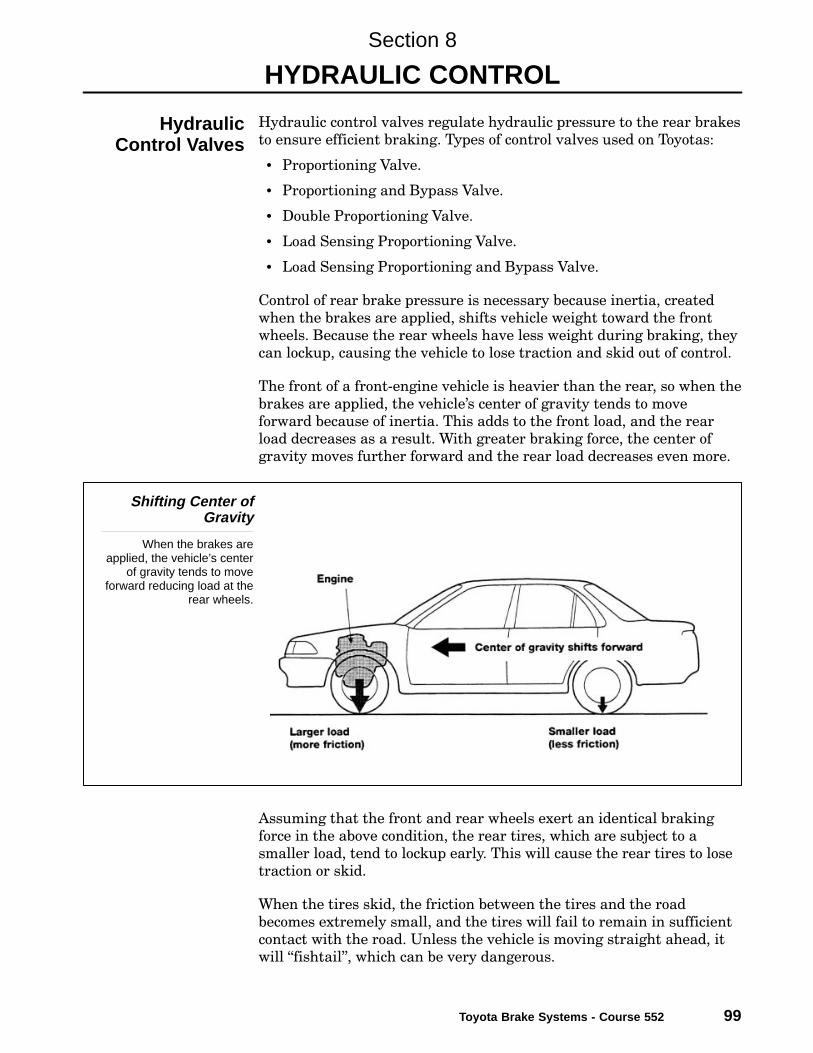
Control of rear brake pressure is necessary because inertia, created
when the brakes are applied, shifts vehicle weight toward the front
wheels. Because the rear wheels have less weight during braking, they
can lockup, causing the vehicle to lose traction and skid out of control.
The front of a front−engine vehicle is heavier than the rear, so when the
brakes are applied, the vehicle’s center of gravity tends to move
forward because of inertia. This adds to the front load, and the rear
load decreases as a result. With greater braking force, the center of
gravity moves further forward and the rear load decreases even more.
Shifting Center ofGravity
When the brakes areapplied, the vehicle’s center
of gravity tends to moveforward reducing load at the
rear wheels.
Assuming that the front and rear wheels exert an identical braking
force in the above condition, the rear tires, which are subject to a
smaller load, tend to lockup early. This will cause the rear tires to lose
traction or skid.
When the tires skid, the friction between the tires and the road
becomes extremely small, and the tires will fail to remain in sufficient
contact with the road. Unless the vehicle is moving straight ahead, it
will �fishtail", which can be very dangerous.
Section 8
HYDRAULIC CONTROL
HydraulicControl Valves

Section 8
100 TOYOTA Technical Training
The braking force of the rear tires must be reduced below that of front
tires in order to prevent early lock−up. This is achieved by the
proportioning valve (P. valve). It is designed to automatically reduce
the hydraulic pressure for the rear wheel cylinders in proportion to
hydraulic pressure from the master cylinder.
Proportioning ValveLocation
The braking force of the reartires must be reduced belowthat of front tires in order to
prevent early lock-up.
The graph below shows an ideal hydraulic pressure curve for the front
and rear wheels (actual values vary from one vehicle model to another).
The proportioning valve is designed to bring actual pressure curves as
close to the ideal as technically possible.
Hydraulic PressureCurve
The P-valve is designed tobring actual pressure curves
as close to the ideal astechnically possible.
Hydraulic PressureCurve

Hydraulic Control
Toyota Brake Systems - Course 552 101
The spring in the Proportioning valve holds the valve in the open
position. During normal braking the brake fluid flows through the
valve without any proportioning action. However, when heavier
braking occurs, pressure on the wheel cylinder side of the
proportioning valve pushes the valve against spring tension and closes
the valve. This in effect reduces pressure to the rear brakes. As
pressure increases on the master cylinder side, it lifts the valve,
increasing pressure to the wheel cylinder side of the valve. As pressure
increases on the wheel cylinder side of the valve, it seats again. This
occurs in rapid succession as long as pressure from the master cylinder
increases.
Proportioning Valve
Pressure on the rear cylinderside pushes the valve
against spring tension andcloses the valve.
Proportioning ValveOperation
Section 8
102 TOYOTA Technical Training
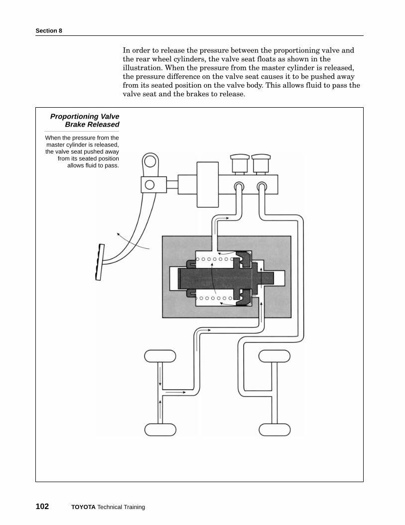
In order to release the pressure between the proportioning valve and
the rear wheel cylinders, the valve seat floats as shown in the
illustration. When the pressure from the master cylinder is released,
the pressure difference on the valve seat causes it to be pushed away
from its seated position on the valve body. This allows fluid to pass the
valve seat and the brakes to release.
Proportioning ValveBrake Released
When the pressure from themaster cylinder is released,the valve seat pushed away
from its seated positionallows fluid to pass.

Hydraulic Control
Toyota Brake Systems - Course 552 103
The proportioning function of this valve is the same as that described
on the previous pages however, a Bypass Valve is incorporated into
the valve body. It ensures maximum braking pressure to the rear
brakes when there is a loss of brake pressure in the front brake circuit.
The hydraulic circuit from the master cylinder to the front brakes flows
through part of the proportioning valve housing where the Bypass
Valve
monitors front brake pressure. The spring pushes the bypass valve to
the left and pushes the proportioning valve to the right, providing the
proper spring tension for proportioning valve operation.
Rear brake hydraulic pressure pushes the bypass valve to the right while
front brake pressure pushes the valve to the left. The overall hydraulic
effect on the valve is neutral and the spring holds it to the left.
Bypass ValveOperation
Spring loaded to the left, thebypass valve establishes the
spring position for normalproportioning operation.
Proportioning andBypass Valve
Operation

Section 8
104 TOYOTA Technical Training
Should the hydraulic circuit to the front brakes fail, rear brake
pressure will move the bypass valve to the right, forcing the
proportioning valve to the right, which allows unregulated pressure to
apply the rear brakes.
Bypass ValveOperation
The bypass valve movesright when front brake
pressure drops, increasingspring tension of the
proportioning valve therebyensuring maximum pressure.
The diagonal split brake system incorporated on all FWD vehicles uses
a double proportioning valve in which two valves are arranged parallel
to one another in the same valve housing. One valve controls pressure
to the right rear brakes and the other valve controls pressure to the left
rear brakes.
Proportioning Valveon Diagonal Split
Brake System
All FWD vehicles use adouble proportioning valve
to control one front brakeand one rear brake on the
opposite side.
Double ProportioningValve
Hydraulic Control
Toyota Brake Systems - Course 552 105
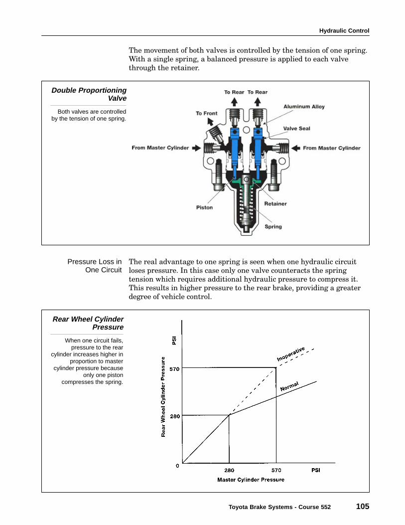
The movement of both valves is controlled by the tension of one spring.
With a single spring, a balanced pressure is applied to each valve
through the retainer.
Double ProportioningValve
Both valves are controlledby the tension of one spring.
The real advantage to one spring is seen when one hydraulic circuit
loses pressure. In this case only one valve counteracts the spring
tension which requires additional hydraulic pressure to compress it.
This results in higher pressure to the rear brake, providing a greater
degree of vehicle control.
Rear Wheel CylinderPressure
When one circuit fails,pressure to the rear
cylinder increases higher inproportion to master
cylinder pressure becauseonly one piston
compresses the spring.
Pressure Loss inOne Circuit
Section 8
106 TOYOTA Technical Training
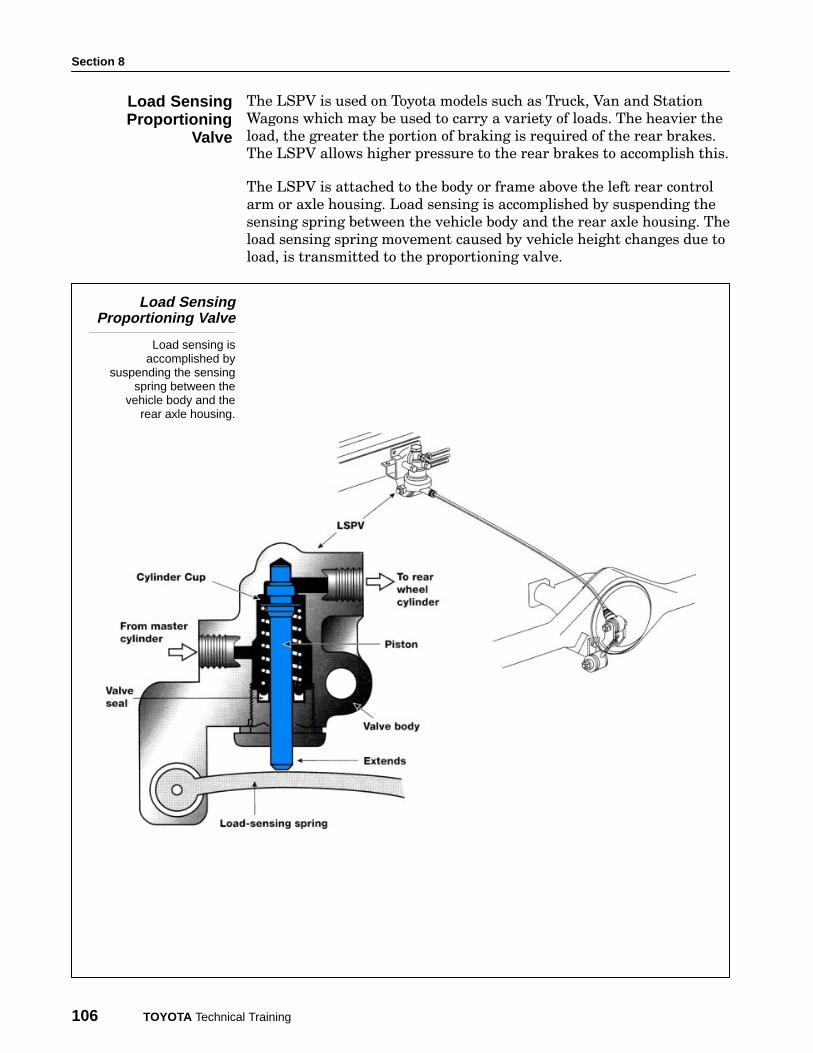
The LSPV is used on Toyota models such as Truck, Van and Station
Wagons which may be used to carry a variety of loads. The heavier the
load, the greater the portion of braking is required of the rear brakes.
The LSPV allows higher pressure to the rear brakes to accomplish this.
The LSPV is attached to the body or frame above the left rear control
arm or axle housing. Load sensing is accomplished by suspending the
sensing spring between the vehicle body and the rear axle housing. The
load sensing spring movement caused by vehicle height changes due to
load, is transmitted to the proportioning valve.
Load SensingProportioning Valve
Load sensing isaccomplished by
suspending the sensingspring between the
vehicle body and therear axle housing.
Load SensingProportioning
Valve

Hydraulic Control
Toyota Brake Systems - Course 552 107
As a vehicle is loaded, the leaf springs are compressed as the vehicle
body lowers. The load sensing spring provides a variable force pushing
the proportioning piston up as the vehicle is loaded. As the piston is
lifted, a higher brake hydraulic pressure is required to force the piston
down resulting in higher pressure at the rear wheels.
LSPV Lever Balance
The load sensing springprovides additional pressure
to the proportioning valvebased on vehicle load.
Rear wheel cylinder pressure is adjusted according to increases or
decreases in vehicle load. The pressure change for one rear wheel is
shown below.
LSPV Rear WheelCylinder Pressure
Pressure to the rear brakesis regulated at a higher
pressure when thevehicle is loaded.
LSPV Operation
Section 8
108 TOYOTA Technical Training
When unloaded, a vehicle body rises to normal vehicle height and no
force from the load sensing spring is applied to the piston. The rear
wheel cylinder is regulated at a lower pressure as shown by the line O
− A − B in the chart on the previous page.
When the fluid pressure from the master cylinder is low the piston is
pushed upward by the force of the piston spring. Fluid pressure is
transmitted from chamber A through the passage into chamber B and
to the rear wheel cylinder.
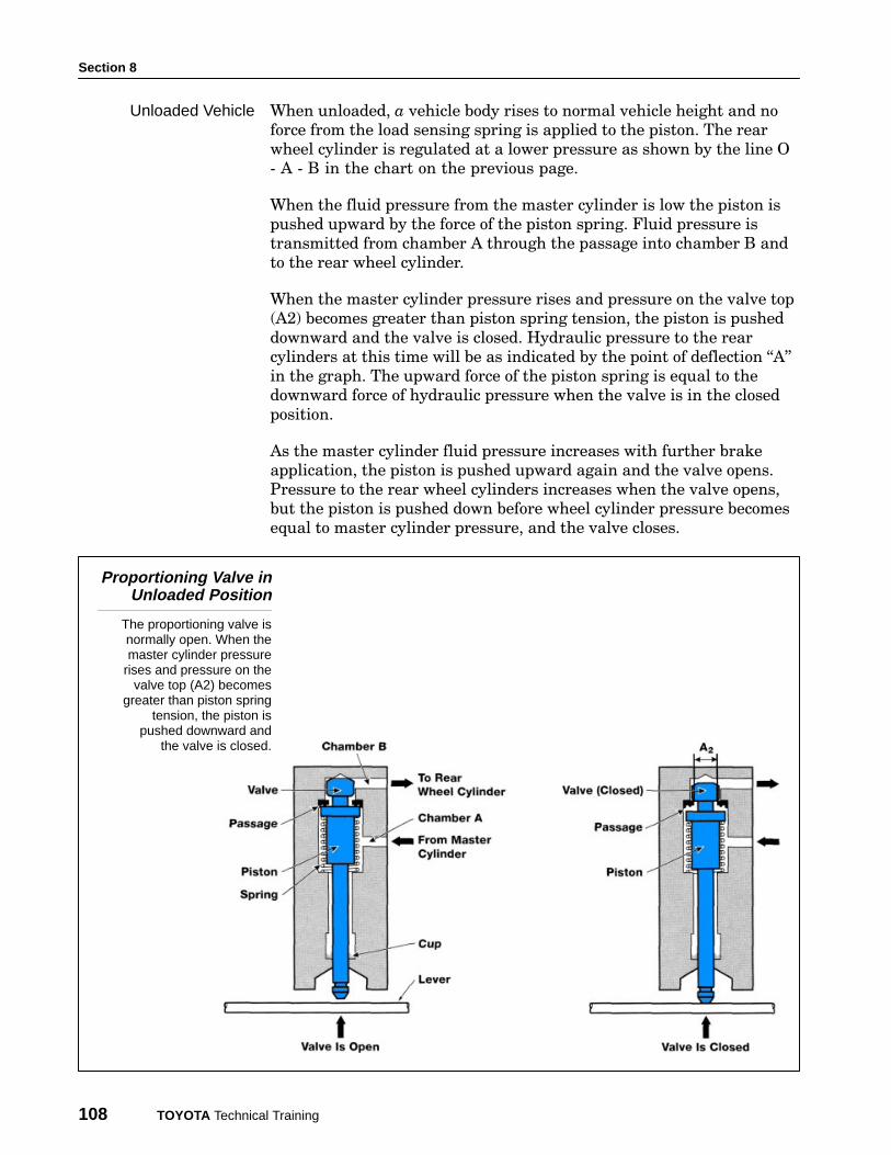
When the master cylinder pressure rises and pressure on the valve top
(A2) becomes greater than piston spring tension, the piston is pushed
downward and the valve is closed. Hydraulic pressure to the rear
cylinders at this time will be as indicated by the point of deflection �A"
in the graph. The upward force of the piston spring is equal to the
downward force of hydraulic pressure when the valve is in the closed
position.
As the master cylinder fluid pressure increases with further brake
application, the piston is pushed upward again and the valve opens.
Pressure to the rear wheel cylinders increases when the valve opens,
but the piston is pushed down before wheel cylinder pressure becomes
equal to master cylinder pressure, and the valve closes.
Proportioning Valve inUnloaded Position
The proportioning valve isnormally open. When themaster cylinder pressure
rises and pressure on thevalve top (A2) becomes
greater than piston springtension, the piston is
pushed downward andthe valve is closed.
Unloaded Vehicle

Hydraulic Control
Toyota Brake Systems - Course 552 109
As the load in the vehicle is increased, the vehicle body moves down, and
the LSPV piston is pushed up by the lever causing the rear wheel cylinder
to be regulated at a higher pressure as shown in the graph (O − C − D).
When the fluid pressure from the master cylinder is low, the hydraulic
pressure going to the rear wheel cylinder is not controlled. As master
cylinder pressure rises and becomes greater than the combined spring
tension, the piston is pushed downward and the valve is closed
regulating pressure to the rear brake cylinder.
Proportioning Valve inthe Loaded Position
The LSPV piston is pushedup by the lever causing the
rear wheel cylinderpressure to increase.
Loaded Vehicle
Section 8
110 TOYOTA Technical Training
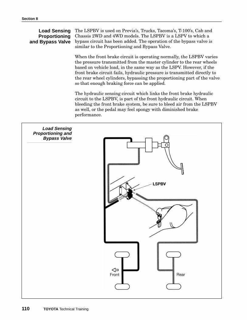
The LSPBV is used on Previa’s, Trucks, Tacoma’s, T−100’s, Cab and
Chassis 2WD and 4WD models. The LSPBV is a LSPV to which a
bypass circuit has been added. The operation of the bypass valve is
similar to the Proportioning and Bypass Valve.
When the front brake circuit is operating normally, the LSPBV varies
the pressure transmitted from the master cylinder to the rear wheels
based on vehicle load, in the same way as the LSPV. However, if the
front brake circuit fails, hydraulic pressure is transmitted directly to
the rear wheel cylinders, bypassing the proportioning part of the valve
so that enough braking force can be applied.
The hydraulic sensing circuit which links the front brake hydraulic
circuit to the LSPBV, is part of the front hydraulic circuit. When
bleeding the front brake system, be sure to bleed air from the LSPBV
as well, or the pedal may feel spongy with diminished brake
performance.
Load SensingProportioning and
Bypass Valve
Load SensingProportioning
and Bypass Valve

Hydraulic Control
Toyota Brake Systems - Course 552 111
When the front brake circuit is operating normally, pressure from the
master cylinder front and master cylinder rear are equal. The bypass
piston is pushed and held down by the spring.
If pressure from the front brakes falls to zero, a difference will exist
between the hydraulic pressure pushing the bypass valve up and the
pressure pushing the valve down. This causes the bypass valve to be
pushed upward, pushing the piston upward, and opening the passage
at the top of the valve. The hydraulic pressure from the master
cylinder is not controlled. Full pressure from the master cylinder is
transmitted to the rear wheel cylinder.
Fail-safe Operation
When pressure from thefront brakes (Pf) is lost,
Piston No. 2 risescompressing the springand opening the valve.
Bypass ValveOperation
Section 8
112 TOYOTA Technical Training
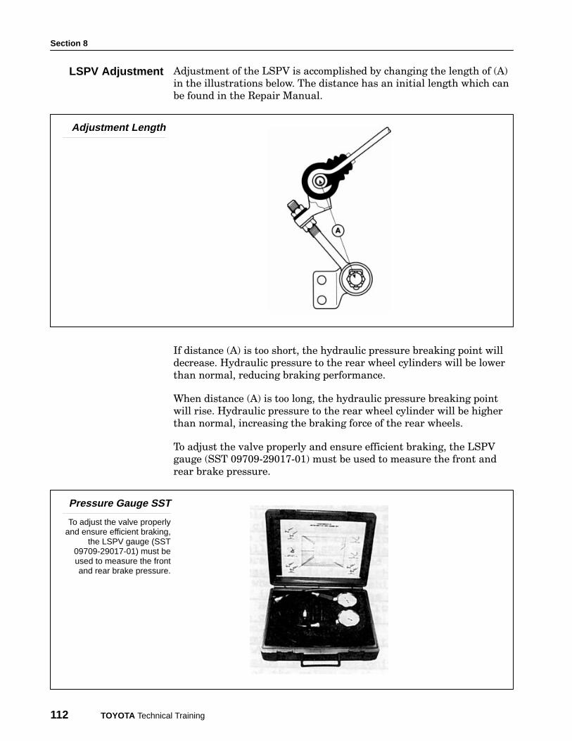
Adjustment of the LSPV is accomplished by changing the length of (A)
in the illustrations below. The distance has an initial length which can
be found in the Repair Manual.
Adjustment Length
If distance (A) is too short, the hydraulic pressure breaking point will
decrease. Hydraulic pressure to the rear wheel cylinders will be lower
than normal, reducing braking performance.
When distance (A) is too long, the hydraulic pressure breaking point
will rise. Hydraulic pressure to the rear wheel cylinder will be higher
than normal, increasing the braking force of the rear wheels.
To adjust the valve properly and ensure efficient braking, the LSPV
gauge (SST 09709−29017−01) must be used to measure the front and
rear brake pressure.
Pressure Gauge SST
To adjust the valve properlyand ensure efficient braking,
the LSPV gauge (SST09709-29017-01) must beused to measure the frontand rear brake pressure.
LSPV Adjustment

Hydraulic Control
Toyota Brake Systems - Course 552 113
The gauges are provided in the SST Kit. Install one gauge at the front
wheel cylinder. The other gauge is installed at the rear wheel cylinder.
Having opened the system, the air must be bled from the system before
accurate system pressures can be read. Bleed screws are located on the
hose end of the gauge.
Follow the procedure outlined in the Repair Manual to determine the
following:
1. Rear axle load (based on vehicle model).
2. Front brake pressure specifications.
3. Rear brake pressure specifications.
The weight of the vehicle measured at the rear axle must be
determined and additional weight added to meet the Repair Manual
specification. This will establish the proper relationship of the
proportioning valve and the rear axle housing.
Hydraulic PressureMeasurement
Hydraulic pressure at thefront brake should be
compared with thepressure of the rear brake
in two stages.
Next, the hydraulic pressure at the front brake should be compared
with the pressure of the rear brake in two or three stages as specified
in the Repair Manual.
• First, the front pressure is brought to a specified pressure
(example: 1,138 psi) and the rear pressure should be within a
specific pressure range (example: 583 psi to 768 psi).
• Second, without releasing the brake pedal, the front pressure is
increased (example: 1,422 psi) and the rear brake pressure should
increase (example: between 688 psi to 873 psi).
Rear pressure readings should be taken within two seconds of
obtaining the specified front pressure.NOTE
Section 8
114 TOYOTA Technical Training
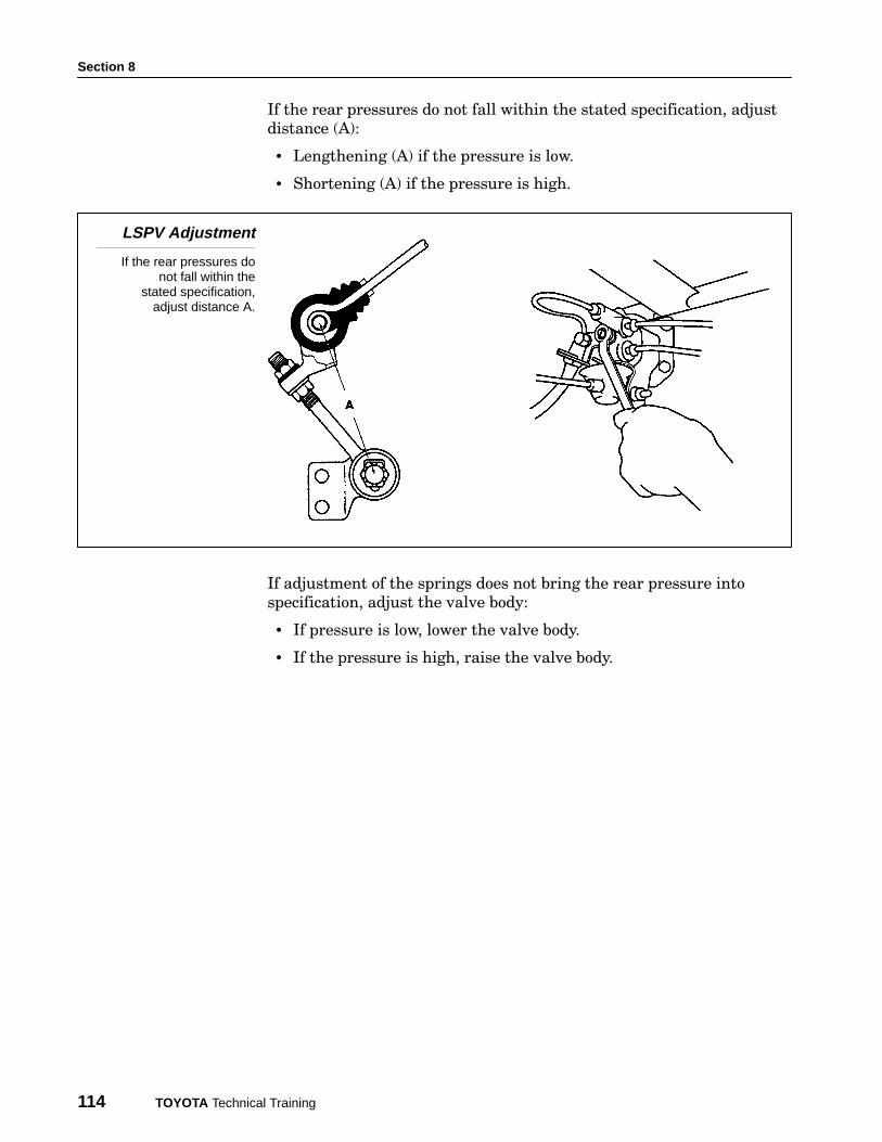
If the rear pressures do not fall within the stated specification, adjust
distance (A):
• Lengthening (A) if the pressure is low.
• Shortening (A) if the pressure is high.
LSPV Adjustment
If the rear pressures donot fall within the
stated specification,adjust distance A.
If adjustment of the springs does not bring the rear pressure into
specification, adjust the valve body:
• If pressure is low, lower the valve body.
• If the pressure is high, raise the valve body.
Hydraulic Control
Toyota Brake Systems - Course 552 115
WORKSHEET 8-1 (ON-CAR)LSPV Adjustment
Vehicle Year/Prod. Date Engine Transmission
Worksheet Objectives
In this Worksheet you will practice the procedure for measuring and adjusting the LSPV.
Tools and Equipment:
• LSPV Pressure Gauge SST. (09709-29017-01)
• Weight Scale Printout.
• Hand Tool Set.
• Tape Measure or Ruler.
• Brake Fluid.
• Repair Manual.
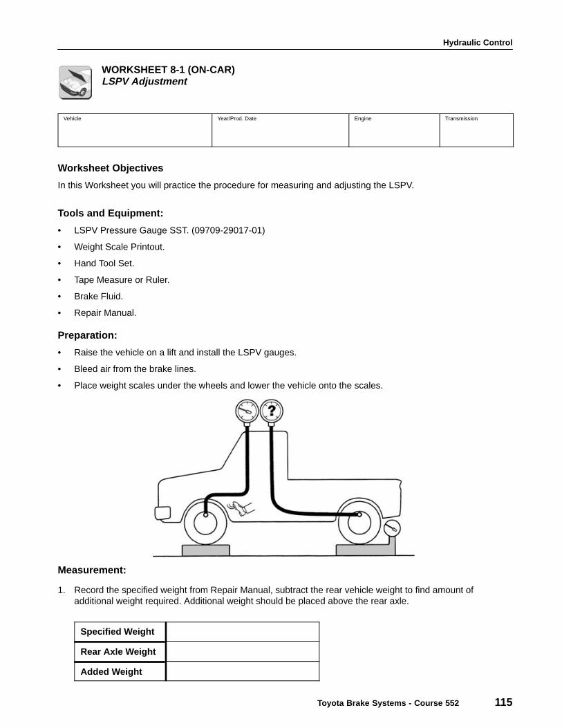
Preparation:
• Raise the vehicle on a lift and install the LSPV gauges.
• Bleed air from the brake lines.
• Place weight scales under the wheels and lower the vehicle onto the scales.
Measurement:
1. Record the specified weight from Repair Manual, subtract the rear vehicle weight to find amount ofadditional weight required. Additional weight should be placed above the rear axle.
Specified Weight
Rear Axle Weight
Added Weight
Section 8
116 TOYOTA Technical Training
Measurement (cont’d):
2. Raise front brake pressure and check rear brake pressure.
Model Front Pressure Spec. Rear Axle Spec. Rear Axle Measured
3. How does this compare to the specified pressure?
LSPV Adjustment:
1. Record the initial length of the No.2 shackle.
2. Rotate the adjusting nut two (2) complete turns and record the change in rear pressure.
3. Recheck the pressures, has the pressure at the rear brakes increased or decreased?
If so, by how much?
Summary:
1. Why is the weighting of the rear of the vehicle important?
2. What effect would mis-adjustment have on the brake system?
3. Refer to the Repair Manual for Previa and Camry and record the pressure change for each rotation of theNo.2 shackle adjusting nut.
4. To increase the pressure at the rear wheels, would the No.2 shackle be shortened or lengthened?
Top Related