


Languages
Pages
Legal


1َدرِنقْْنصدق اننالما،،، ِنـْقـَدر

2
The software architecture of a program or computing
system is the structure (or structures) of the system,
including:
Dividing software into subsystems.
Deciding how these will interact.
Determining their interfaces.
• The architecture is the core of the design, so all software
engineers need to understand it.
• The architecture will often constrain the overall efficiency,
reusability and maintainability of the system
3
Why you need to develop an architectural model:
To enable everyone to better understand the system
To allow people to work on individual pieces of the system
in isolation
To prepare for extension of the system
To facilitate reuse and reusability

4
An architecture is an abstraction of a system that
suppresses details of components that do not affect how
they:
Use other components
Are used by other components
Relate to other components
Interact with other components

5
To ensure the maintainability and reliability of a system,
an architectural model must be designed to be stable.
Being stable means that the new features can be easily
added with only small changes to the architecture.

6
aTruck aShip aAirplane theWarehouseCollecti on
theVehicleCollection
UML-A Generated Dependency Class:theRouter Dependency (1.0)
theStorage
aVehicle
UML-A Generated Dependency Class:theRouter Dependency (0.5)
availableVehicleCollection
UML-A Generated Association Class:theVehicleCollection Generalization (1.0)UML-A Generated Association Class:theVehicleCollection Generalization (1.0)UML-A Generated Association Class:theVehicleCollection Generalization (1.0)UML-A Genera ted As socia tion C lass: theVehicleC ollec tion Genera lization (1.0)UML-A Generated Association Class:theVehicleCollection Generalization (1.0)UML-A Generated Association Class:theVehicleCollection Generalization (1.0)UML-A Generated Association Class:theVehicleCollection Generalization (1.0)UML-A Generated Association Class:theVehicleCollection Generalization (1.0)UML- A Generated Ass ociati on Cl ass:theVehi cleCo llection Generali zation (1.0 )UML-A Generated Association Class:theVehicleCollection Generalization (1.0)
UML-A Generated Dependency Class:theRouter Dependency (1.0)
availableGoods
aPort
aPortC ollec tion
aSurp lus aDifficiency
theTimeNeeded
theGoods
UML-A Generated Association Class:aWarehouse Association (0.5)
UML-A Generated Association Class:aWarehouse Association (0.5)
UML-A Generated Association Class:availableGoods Association (0.5)
aRouteCollection
UML-A Generated Association Class:aRoute Association (0.25)UML-A Generated Association Class:aRoute Association (0.25)UML-A Generated Association Class:aRoute Association (0.25)UML-A Generated Association Class:aRoute Association (0.25)
UML-A Generated Dependency Class:theRouter Dependency (0.5)UML-A Generated Dependency Class:theRouter Dependency (1.0)
UML-A Generated Dependency Class:theRouter Dependency (1.0)
theAWT
aVehiceDialog aWarehouseDialog aPortDialog aRouterDialog
aWarehouse
UML-A Generated Association Class:aDifficiency Association (1.0)UML-A Generated Association Class:aDifficiency Association (1.0)
UML-A Generated Association Class:aDifficiency Association (1.0)UML-A Generated Association Class:aDifficiency Association (1.0)
UML-A Generated Association Class:aDifficiency Association (1.0)U ML-A Generated Association Class:aD ifficiency Associ ation (1.0)UML-A Generated Association Class:aDifficiency Association (1.0)UML-A Generated Association Class:aDifficiency Association (1.0)U ML-A Generated Association Class:aD ifficiency Associ ation (1.0)UML-A Generated Association Class:aDifficiency Association (1.0)
UML-A Genera ted Associ ation C lass:aSurp lus Associ ation (1.0)UML-A Generated Association Class:aSurplus Association (0.5)
UML-A Generated Associ ation Class:aRoute Association (0.5)
aLocation
UML-A Generated Association Class:aNavPoint Association (1.0)
UML-A Generated Association Class:aWarehouse Association (0.5)
UML-A Generated Association Class:aNavPoint Association (0.5)
UML-A Generated Association Class:aNavPoint Association (0.5)UML-A Generated Association Class:aNavPoint Association (0.5)
UML-A Generated Association Class:aWarehouse Association (0.5)aNavPoint
UML-A Generated Association Class:aWarehouse Association (1.0)
UML-A Generated Association Class:aWarehouse Association (0.5)UML-A Generated Association Class:aWarehouse Association (0.5)
UML-A Generated Association Class:aWarehouse Association (0.5)
UML-A Generated Association Class:aWarehouse Association (0.5)
UML-A Generated Association Class:aRoute Association (0.5)
aRoute
UML-A Genera ted Dependency C lass :aRouteCol lection Ass ociation (0.25)
UML-A Generated Association Class:aNavPoint Association (1.0)UML-A Generated Association Class:aNavPoint Association (0.5)
UML-A Generated Association Class:aWarehouse Association (1.0)
UML-A Generated Dependency Class:aRouteCollection Association (0.5)
UML-A Generated Association Class:aNavPoint Association (1.0)UML-A Generated Association Class:aNavPoint Association (1.0)UML-A Generated Association Class:aNavPoint Association (1.0)UML-A Generated Association Class:aNavPoint Association (1.0)UML-A Generated Association Class:aNavPoint Association (1.0)
UML-A Generated Association Class:aNavPoint Association (0.25)UML-A Generated Association Class:aNavPoint Association (0.25)
UML-A Generated Association Class:aNavPoint Association (0.25)
UML-A Generated Dependency Class:theRouter Association (0.25)
UML-A Generated Association Class:aNavPoint Association (0.25)
theCargoRouter
UML-A Generated Association Class:theRouter Association (0.25)
UML-A Genera ted As socia tion C lass: theWarehouseCollection Dependency ( 0.25)
UML-A Generated Association Class:theRouter Association (0.25)
UML-A Generated Association Class:theRouter Association (0.25)
t heRouter
UML-A Generated Association Class:theWarehouseCollection Dependency (0.5)
UML-A Generated Association Class:theWarehouseCollection Dependency (0.5)
UML-A Genera ted Dependency Class :aRouteCollection Ass ociation (0.5)UML-A Generated Association Clas s:theWarehouseCollec tion Dependency (0.5)
UML-A Generated Association Class:theVehicleCollection Dependency (0.5)UML-A Generated Association Class:availableVehicleCollection Dependency (0.5)UML- A Generated Generaliz ation Class :avail ableVehicleCollection Dependenc y (1.0 )
UML-A Generated Dependency Class:theRouter Association (0.25)
UML-A Generated Dependency Class:theRouter Association (0.5)UML-A Generated Dependency Class:theRouter Association (1.0)
UML-A Generated Dependency Class:theRouter Association (0.5)
UML-A Generated Dependency Class:theWarehouseCollection Dependency (1.0)
UML-A Generated Dependency Class:theRouter Association (1.0)UML-A Generated Dependency Class:theRouter Association (1.0)
This is a simplesoftware system!

7
8
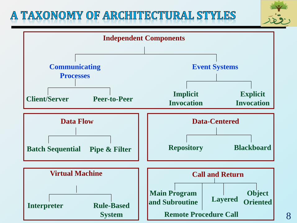
Independent Components
Communicating
Processes
Event Systems
Client/Server Peer-to-PeerImplicit
Invocation
Explicit
Invocation
Data Flow
Batch Sequential Pipe & Filter
Virtual Machine
Interpreter Rule-Based
System
Data-Centered
Repository Blackboard
Call and Return
Main Program
and Subroutine
Object
OrientedLayered
Remote Procedure Call

9
Shared Data
Client A Client B Client C
Client D Client E Client F

10
Has goal of achieving the quality of integrability of data.
The term refers to systems in which the access and update
of a widely accessed data store is their primary goal.
Basically, it is nothing more than a centralized data store
that communicates with a number of clients.
Important for this styles are three protocols:
communication, data definition and data manipulation
protocol
A client runs on an independent thread of control.
The means of communication distinguishes the two
subtypes: repository and blackboard
Repository: a client sends a request to the system to performa necessary action (e.g. insert data)
Blackboard: the system sends notification and data tosubscribers when data of interest changes, and is thus active

11
Ensures data integrity
Reliable, secure, easy to Backup, testability guaranteed
Clients independent on the system: performance and
usability on the client side is good
Problems with scalability
Solutions: shared repositories, replication but this
increases complexity

12
One of the most well-known examples of the data-centered architecture, is a database architecture
E.g. in RDBMS a set of related tables with fields, datatypes, keys, ...
Clients use data manipulation protocol to work with thedata
E.g. SQL for inserting, selecting, deleting data, ...
Depending on where clients are situated communicationprotocol might be
An inner-process communication
Communication between components on the same machine
Communication over network, e.g. LAN, Internet, etc.

13
Has the goal of achieving the quality of reuse and
modifiability.
The data-flow style is characterized by viewing the system
as a series of transformations on successive pieces of input
data.
Data enter the system and then flows through the
components one at a time until
Finally, the data is assigned to some final destination
(output or a data store).
The architecture is very flexible.
Almost all the components could be removed.
Components could be replaced.
New components could be inserted.
Certain components could be reordered.

14
Validate Sort Update Report

15
Batch sequential style
The processing steps are independent components
Each step runs to completion before the next step begins
Pipe-and-filter style
Emphasizes the incremental transformation of data by
successive components
The filters incrementally transform the data (entering and
exiting via streams)
The pipes are stateless and simply exist to move data
between filters
Note That: It is easily made into a parallel or distributedexecution in order to enhance system performance

16
Data flows through pipes: communication channels
between filters
Processing units: filters
Filters do not know anything about other filters
Modularity, maintainability is good
Data flows in streams: good for processing of images,
audio, video, ...
Depending on where the filters reside different
execution architectures
E.g. same process: filters run within threads
E.g. same machine: filters run within own processes
E.g. network: pipes use the networking architecture

17
Pipe and Filter Example:
Traditional Compilers: Compilation phases are pipelined,
though the phases are not always incremental. The phases
in the pipeline include
• lexical analysis + parsing + semantic analysis + code
generation

18
Main module
Subroutine ASubroutine B
Subroutine A-1 Subroutine A-2
Physical layer
Data layer
Network layer
Transport layer
Application layer Class WClass V
Class X
Class Z
Class Y

19
Has the goal of modifiability and scalability
Has been the dominant architecture since the start of
software development
Main program and subroutine style
Decomposes a program hierarchically into small pieces (i.e.,
modules)
Typically has a single thread of control that travels through
various components in the hierarchy
Remote procedure call style
Consists of main program and subroutine style of system that is
decomposed into parts that are resident on computers
connected via a network
Strives to increase performance by distributing the computations
and taking advantage of multiple processors
Incurs a finite communication time between subroutine call and
response.

20
Object-oriented or abstract data type system
Emphasizes the bundling of data and how to manipulate and
access data
Keeps the internal data representation hidden and allows access
to the object only through provided operations
Permits inheritance and polymorphism
Layered system
Assigns components to layers in order to control inter-
component interaction
Only allows a layer to communicate with its immediate neighbor

21
Layering: the structure of the system is organized into
set of layers
Each layer in on the top of another layer, each layer
communicates only with the layer immediately below it.
The higher layer sees the lower layer as a set of services.
Well-defined interfaces between layers
Reduces complexity,
improves modularity,
reusability,
maintainability

22
Typically organized into layers
Successive layers provide more sophisticated services to
the layers above them
Hardware services, kernel services, system services, UI
services

23
A virtual machine implements an
instruction set for an imaginary
machine
Often virtual machines are the
underplaying mechanism by which
a programming language is
executed
E.g. Java virtual machine, different
interpreters
• Specifies an interface between
compiler and a real machine
From conceptual point of view very
similar to OS
Improves portability

24
A common example of layered architecture is a network
protocol stack
E.g. TCP/IP protocol stack - Four layers
The lowest layer: handles communication between two
computers
The internet layer: handles routing of packets across the
network
The transport layer: guarantees that packets are error-
free and received in the same order as sent
The application layer: supports application-specific
protocols
• E.g. HTTP, SMTP, FTP, ...

25

26
Basic concept:
The client uses a service
The server provides a service
Typically connected via a network
Clients are independent from each other
There is at least one component that has the role of
client, initiating connections in order to obtain some
service.

27
Conceptually simple
Clear separation of responsibilities, help testability
Good scalability (if stateless)
Excellent scalability (if server can be scaled out)
Good for security, as data can be held at the server with
restricted access
Risk of bad performance, if the communication between
client and server is slow, or has a high latency
Need to develop/agree on a protocol between client and
server
For stateful, centralized servers scalability is limited

28
The server is no longer in the organizations network, but
somewhere in the Internet
Example: cloud services by Salesforce, Google,
Microsoft
Scalability, security, reliability is expected to be
handled by a specialized team
Needs a working Internet connection

29
Separation between client and server is removed
Each client is a server at the same time, called peer
The goal is to distribute the processing or data among many
peers
No central administration or coordination
29

30
Example: Skype uses a peer-to-peer protocol, but also
uses super-nodes and a central login servers
Adv.
Good for scalability
Good for reliability, as data can be replicated over peer
No single point of failure
Disadv.
Quality of service is not deterministic, cannot be guaranteed
Very complex, hard to maintain and test

31
The N-tier architecture is the modern client-server
architecture
Originated with business applications
Through the popularity of the Web today typically
related with Web applications
Conceptually separate architecture into:
Presentation,
Application, and
Data storage layers.

32
Clients are typically rich
(ui + app-logic + communication)
Servers store data
Each client runs a complete application
Drawbacks: each client has to know how to
communicate with all data servers
Scalability is compromised because client are tightly
coupled with servers

33
Evolved from 2-tier architectures to solve
their drawbacks
A third tier is inserted between clients
and data servers
Application or business logic tier: middle
tier.
Typically middle tier is on the server side
(but recently might be split between the
server and the client)
Scalability improved because clients are
thinner.
Thin clients have no knowledge on
application
A rich client contains full knowledge of
application

34
Suitable for applications in which a central issue is
identifying and protecting related bodies of data.
Data representations and their associated operations are
encapsulated in an abstract data type.
Components: are objects.
Connectors: are function and procedure invocations
(methods).

35
Object-Oriented Invariants
The data representation is hidden from other objects.
Advantages
it is possible to change the implementation without
affecting those clients.
Can design systems as collections of autonomous
interacting agents.
Disadvantages
In order for one object to interact with another object (via
a method invocation) the first object must know the
identity of the second object
Objects cause side effect problems:
• E.g., A and B both use object C, then B’s effects on C look
like unexpected side effects to A.

36

37
Suitable for applications that involve loosely-coupled
collection of components, each of which carries out
some operation and may in the process enable other
operations.
Instead of invoking a procedure directly ...
A component can announce (or broadcast) one or more
events.
Other components in the system can register an interest in
an event by associating a procedure with the event.
When an event is announced, the broadcasting system
(connector) itself invokes all of the procedures that have
been registered for the event.

38
Advantages:
Provides strong support for reuse.
Eases system evolution
Disadvantages:
When a component announces an event:
• it has no idea what other components will respond to it,
• it cannot rely on the order in which the responses are
invoked
• it cannot know when responses are finished
Twitter, Google+

39
Remote invocation architectures involve distributed
processing components
Typically, a client component invokes a method
(function) on a remote component
E.g. Web services
Advantages:
increased performance through distributed computation
Disadvantages:
tightly coupling of components
increases communication overhead

40
Transparently distribute
aspects of the software
system to different nodes
An object can call
methods of another
object without knowing
that this object is
remotely located.

41
Systems are seldom built from a single architectural
style
Three kinds of heterogeneity:
Locationally heterogeneous
• The drawing of the architecture reveals different styles in
different areas (e.g., a branch of a call-and-return system
may have a shared repository)
Hierarchically heterogeneous
• A component of one style, when decomposed, is structured
according to the rules of a different style
Simultaneously heterogeneous
• Two or more architectural styles may both be appropriate
descriptions for the style used by a computer-based system

42َدرِنقْْنصدق اننالما،،، ِنـْقـَدر

43
Are concerned with the control flow between sub-
systems.
Centralized control
One sub-system has overall responsibility for control and
starts and stops other sub-systems
Event-based control
Each sub-system can respond to externally generated
events from other sub-systems or the system’s
environment

44
A control sub-system takes responsibility for managing
the execution of other sub-systems
Call-return model
Top-down subroutine model
Control starts at the top of a subroutine hierarchy and
moves downwards.
Applicable to sequential systems
Manager model
One system component controls the stopping, starting
and coordination of other system processes.
Applicable to concurrent systems.

45
Routine 1.2Routine 1.1 Routine 3.2Routine 3.1
Routine 2 Routine 3Routine 1
Mainprogram

46
Systemcontroller
Userinterface
Faulthandler
Computationprocesses
Actuatorprocesses
Sensorprocesses

47
Driven by externally generated events where the
timing of the event is outside the control of the sub-
systems which process the event
Two principal event-driven models:
Broadcast models. An event is broadcast to all sub-
systems. Any sub-system which can handle the event
may do so
Interrupt-driven models. Used in real-time systems
where interrupts are detected by an interrupt handler
and passed to some other component for processing

48
Sub-system1
Event and message handler
Sub-system2
Sub-system3
Sub-system4

49
Handler1
Handler2
Handler3
Handler4
Process1
Process2
Process3
Process4
Interrupts
Interruptvector

50
Top Related