


Languages
Pages
Legal


SDN in SP WAN TECH-SDN-SP
David Jakl Systems Engineer

Agenda
SDN in SP WAN
Multi-Layer SDN
PCEP
BGP Link State
BGP Flowspec
Segment Routing
Summary

SDN enables IP/MPLS evolution to a hybrid control-plane centralized control improves network operations and optimization
Applications Applications
Controller
Evolution
Applications Applications
• Distributed Control remains best for many use-cases; e.g. IGP convergence
• Centralized Control introduces new value; e.g. TE placement optimization
4

SDN WAN Transport – Use Cases
• Global Load Balancing
• Multi Layer Optimization
• Coordinated Maintenance • LSP splitting and merging
• Network Rearranging
• Segment Routing
Optimization
• Bandwidth Calendaring with Hybrid Cloud
• Premium Bandwidth
• Path Diversity • Latency Based Forwarding
Monetization
5

Another Perspective of Offline vs Online SDN WAN Orchestration
When the planning inputs change almost on a hourly basis and the network load is close to the max-link-load objective
Tra
ffic
change fr
equency
annual
quarter
monthly
weekly
daily
hourly
Load / Link
25% 50% 75% 100%
Planning
(offline)
SDN WAN
(online)
Source: Clarence Filsfils
6

NB API
Plan
Optimization &
Prediction
Analytics
Collector Deployer
Calendaring
Orchestration
Our SDN WAN Orchestration Platform Evolving …
Optical
IPv4/IPv6/MPLS Segment Routing
Apps
RESTCONF
7

SDN WAN Orch Use-Case #5: Maintenance Window Scheduling
SDN WAN Orch
Collector Deployer
NB API
WAN
R1
R2
R3
1
4
Customers DC/Clouds
① Network conditions reported to collector
② Ops selects Ra, Rb and maint window time
③ Maint Window request: <Ra, Rb, Window>
④ SDN W-O returns impact and changeover plan. Ops confirms
⑤ At Maint Win start SDN W-O re- arranges traffic to bypass Ra, Rb
2
3
PCEP 5
8
Ra Rb
Ops

The Multi-Layer Optimization – nLight
The new DWDM layer enables a truly Converged IP+Optical Transport
Scalable more than 8Tb/s per fiber, based on 100+Gb/s DWDM channels
Flexible, fully non-blocking wavelength switching
BUT…
– Past: Optical BW was relatively cheap throw optical BW at the problem
– Future: Optical BW most expensive part of CapEx need to use it efficiently
SDN transport enables Converged network optimization
– SLA aware routing (e.g. min Latency) or Cost aware routing (e.g. min regens)
– Link failure Restoration can lead to 20+% savings, by reusing available router ports
SDN innovation most important for Converged Transport
The IP/MPLS evolution to SDN is an important innovation!
Optical control, always mainly centrally controlled (NMS)!
SDN Controller (WAN O)
9

Multi-Layer IP/Optical PCE Models (Examples)
Separate PCE
– Operates on each layer
– Optional inter-layer PCE communications
Single-Layer PCE
– Visibility into L3 and optical topologies
– Programs L3 and L3 UNI to optical
10
VNTM = Virtual Network Topology Manager

SDN WAN Use-Case #9: SDN WAN Orch Triggered GMPLS Setup
SDN WAN Orch
Collector Deployer
NB API
R1 R2
1
2
3
① Realtime data collection reveals trending congestion (Rc-Rb link) imminent
② Ops App requests Multi-layer optimization
③ SDN W-O programs Ra and Rb to initiate GMPLS Setup
④ New Ra-Rb link is injected into IP/MPLS Topology
ML Path
Optimization App
Ra Rb
Rc
O1 O2
Congested!!
PCEP
GMPLS UNI GMPLS UNI
4
11
Ops

PCEP BGP Link State BFP Flowspec
12

PCE Architecture
Addresses complex requirements for path computation in large, multi-domain and multi-layer networks
Path computation element (PCE) – Computes network paths based on network information (topology, paths, etc.)
– Stores TE topology database (synchronized with network)
– May reside on a network node or on out-of-network server
– May initiate path creation
– Stateful - stores path database included resources used (synchronized with network)
– Stateless - no knowledge of previously established paths
Path computation client (PCC) – May send path computation requests to PCE
– May send path state updates to PCE
PCC and PCE communicate via Path Computation Element Protocol (PCEP)
Cisco innovation, standardization started in 2005
First implementation (stateless PCC/PCE on network nodes) released in IOS XR 3.5.2 for inter-area TE
Cisco WAN orchestration provides network path instantiation driven by an out-of-network stateful PCE
13
H E L L O my name is
PCE

Stateful PCE
Introduces PCEP extensions for
– LSP state synchronization betw een PCCs and PCEs
– PCC delegation of LSP control to PCE
Passive stateful PCE – PCC maintains state synchronization w ith PCE
– PCC exclusively controls LSP
– PCE does not modify LSP state
Active stateful PCE – PCC maintains state synchronization w ith PCE
– PCC may delegate LSP control to PCE
Either PCE or PCC can initiate LSP setup
PCC always owns LSP state
Cisco WAN orchestration solution relies on an active stateful PCE that initiates LSP setup
14
PCEP
Stateful PCE
TED
LSP DB
PCC
PCE-initiated
LSP
BGP Link State
15
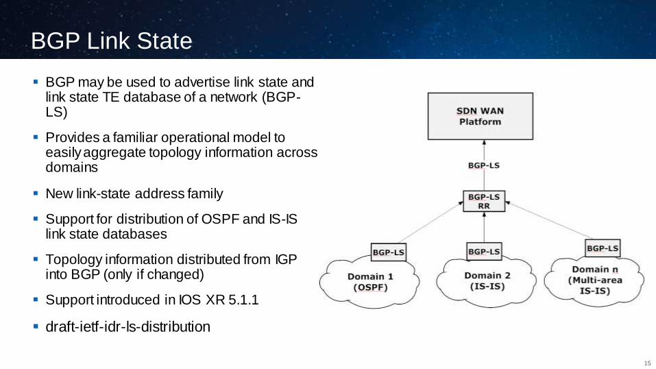
BGP may be used to advertise link state and link state TE database of a network (BGP-LS)
Provides a familiar operational model to easily aggregate topology information across domains
New link-state address family
Support for distribution of OSPF and IS-IS link state databases
Topology information distributed from IGP into BGP (only if changed)
Support introduced in IOS XR 5.1.1
draft-ietf-idr-ls-distribution
BGP Flowspec for SDN WAN Orchestration
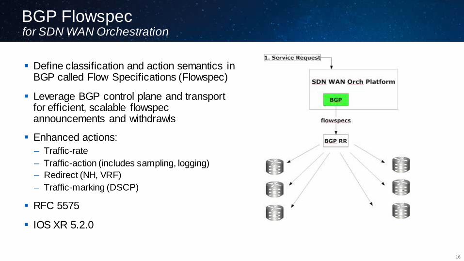
Define classification and action semantics in BGP called Flow Specifications (Flowspec)
Leverage BGP control plane and transport for efficient, scalable flowspec announcements and withdrawls
Enhanced actions:
– Traffic-rate
– Traffic-action (includes sampling, logging)
– Redirect (NH, VRF)
– Traffic-marking (DSCP)
RFC 5575
IOS XR 5.2.0
16
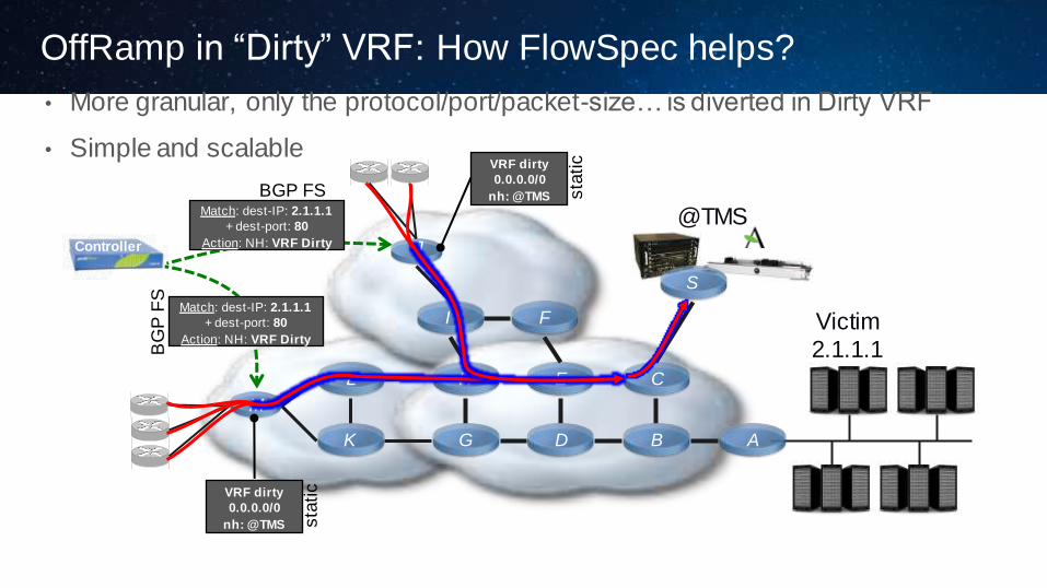
OffRamp in “Dirty” VRF: How FlowSpec helps?
• More granular, only the protocol/port/packet-size… is diverted in Dirty VRF
• Simple and scalable
Controller
Victim
2.1.1.1
A B
C
D
E
F
G
H
I
K
J
L
M
S
@TMS
RR
IPv4
BGP FS Match: dest-IP: 2.1.1.1
+ dest-port: 80
Action: NH: VRF Dirty
BG
P F
S
VRF dirty
0.0.0.0/0
nh: @TMS sta
tic
VRF dirty
0.0.0.0/0
nh: @TMS sta
tic
Match: dest-IP: 2.1.1.1
+ dest-port: 80
Action: NH: VRF Dirty

Segment Routing
18
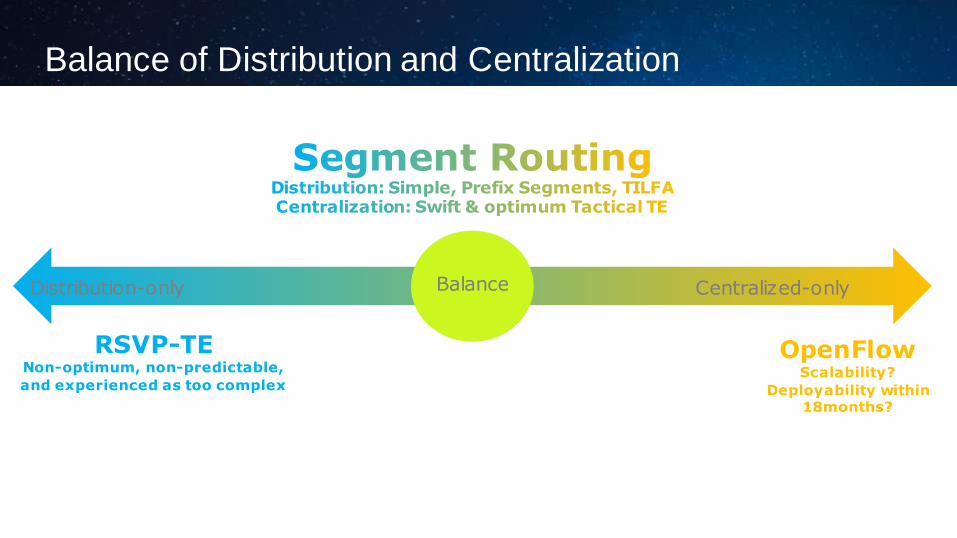
Balance of Distribution and Centralization
RSVP-TE Non-optimum, non-predictable,
and experienced as too complex
OpenFlow Scalability?
Deployability within 18months?
Balance Distribution-only Centralized-only
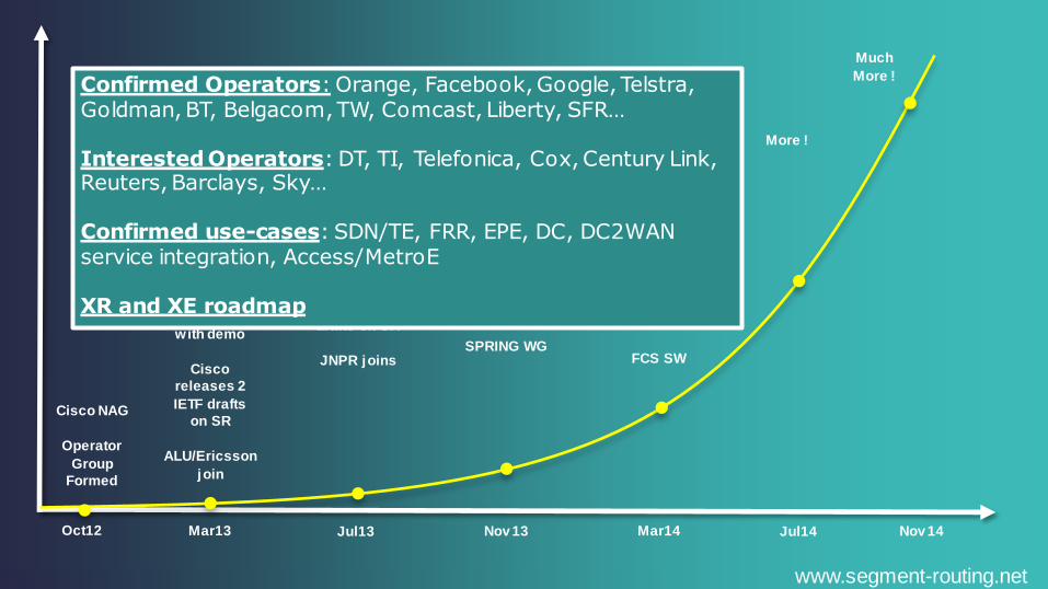
Oct12 Mar13 Jul13 Nov 13 Mar14 Jul14 Nov 14
Cisco
presents SR
at MPLS WC
with demo
Cisco
releases 2
IETF drafts
on SR
ALU/Ericsson
join
Cisco NAG
Operator
Group
Formed
Cisco
releases a
total of 8 IETF
drafts on SR
JNPR joins
Cisco
presents
TI-LFA with
demo
12 IETF drafts
SPRING WG
One-year
first-public
presentation
birth day
SR/TE first
public demo
15 IETF drafts
FCS SW
More !
Much
More !
www.segment-routing.net
Confirmed Operators: Orange, Facebook, Google, Telstra, Goldman, BT, Belgacom, TW, Comcast, Liberty, SFR… Interested Operators: DT, TI, Telefonica, Cox, Century Link, Reuters, Barclays, Sky… Confirmed use-cases: SDN/TE, FRR, EPE, DC, DC2WAN service integration, Access/MetroE XR and XE roadmap

21
• Simple extension to IS-IS or OSPF, automatically builds and maintains Segments
Nodal Segment – A Shortest path to the related node
Adjacency Segment – One hop through the related adjacency
• Excellent Scale: a node installs N+A FIB entries
N = nodal segments; A = adjacency segments
A B C
M N O
Z
D
P
Nodal segment to C
Nodal segment to Z
Adj Segment
Nodal segment to C

22
• Node Z advertises its node segment (loopback 0)
e.g. in ISIS its just a simple ISIS sub-TLV extension
• All remote nodes install the node segment to Z in the MPLS dataplane
A B C
Z
D
65
FEC Z
push 65
swap 65
to 65
swap 65
to 65 pop 65
A packet injected anywhere
with top label 65 will reach Z
via shortest-path Packet to Z Packet to Z
65
Packet to Z
65
Packet to Z
65
Packet to Z
23
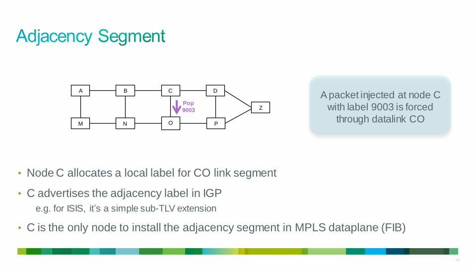
• Node C allocates a local label for CO link segment
• C advertises the adjacency label in IGP
e.g. for ISIS, it’s a simple sub-TLV extension
• C is the only node to install the adjacency segment in MPLS dataplane (FIB)
A B C
M N O
Z
D
P
Pop
9003
A packet injected at node C
with label 9003 is forced
through datalink CO

24
• Source Routing along with the explicit path, stack of nodal and adjacency segments
• Any explicit path can be expressed: e.g. ABCOPZ
• ECMP
Node segment
• Per-flow state only at head-end
not at midpoints
• Source Routing
the path state is in the packet header
A B C
M N O
Z
D
P
9003
Packet to
Z
65
9003
Packet to
Z
65
Packet to Z
Packet to Z
65
Packet to
Z
65
9003
72
Packet to
Z
65
9003
72
72 72
65
65

25
• Efficient packet networks leverage ecmp-aware shortest-path!
node segment!
• Simplicity
no complex LDP/ISIS synchronization to troubleshoot
one less protocol to operate
A B
M N
PE2 PE1
All VPN services ride on the node segment
to PE2
IPv4 over MPLS/IGP VPN over MPLS/IGP
Internet over MPLS/IGP PW over MPLS/IGP
IPv6 over MPLS/IGP

26
• SR router scales much more than with RSVP-TE
The state is not in the router but in the packet
Node + Adj vs. Node 2̂
• No requirement of RSVP-TE protocol
And knobs such as LDPoRSVP etc.
PE
PE
PE
PE
PE
PE
PE
PE
P
In Label Out Label Out
Inter face
L1 L1 Intf1
L2 L2 Intf1
… … …
L8 L8 Intf4
L9 Pop Intf2
L10 Pop Intf2
… … …
Ln Pop Intf5
Node Segment Ids
Adjacency Segment Ids
FIB remains constant

27
draft-francois-segment-routing-ti-lfa
• Guaranteed Link/Node FRR in any topology
even w ith asymmetric metrics
• No Directed LDP session
• Simplicity
entirely automated (no need for customization)
• Incremental deployment
Applicable to LDP and IP primary traff ic
Only the repair tunnel is SR-based
• For networks with symmetric metric & link protection
No extra computation
Simple repair stack
Node segment to P node
Adjacency segment from P to Q
• Demo available
Backbone
C1 C2
E1 E4
E3 E2
1000
Node segment to P node
Default metric: 10
Adj segment to Q node

28

SR with WAN Orchestration
WAN O allows for the best possible simplification of SR
– Optimum state computation
– A single touch-point at the Source Node
– Instant set-up time
Also a stateful PCE, as with MPLS-TE, can be help to:
– Compute globally optimum paths for traffic-engineered SR tunnels
– Instantiate SR tunnels based on requests from applications
– Instantiate traffic steering onto the instantiated tunnel
Minimal changes – PCEP capability to negotiate SR between PCE and PCC
– IGP capability used by PCE’s to advertise their SR/PCE capability
– Extension to BGP-LS to convey the segments
– Extension to IR2S policy retrieval to include segment information
– Minimal changes in (Cisco) CLI and look and feel stays same
1 0
B
Ask for path to G
with certain SLA
(delay, bandwidth,
duration, etc)
SDN WAN O
Indentify best
path and
segments (B, D,
C, E, G)
A
D
C
F
E
G
29

Summary
30

Summary
SDN WAN
PCEP
BGP Link State
BGP Flowspec
Segment Routing

Orchestrated Networks
Network-aware Apps
Programmatic Interfaces (& Overlays)
Segment Routing,
IP+Optical Convergence
Technology Objectives
Make everything go faster, easier and more agile
Configurable Networks
Apps-aware Networks
Network Interfaces
Simplify Networks
32

Scenario 1: Using ECMP
Scenario 2: Using One Path of ECMP
Scenario 3: Using Anycast Segment
Scenario 4: Not Using Shortest Path
Scenario 5: Traversing Links

Prosíme, ohodnoťte tuto přednášku
• Děkujeme

Top Related