


Languages
Pages
Legal

SDM 081
S-DIAS Safety
Digital Mixed Module
Date of creation: 12.05.2014 Version date: 02.04.2019 Article number: 20-895-081-E
Publisher: SIGMATEK GmbH & Co KG
A-5112 Lamprechtshausen
Tel.: +43/6274/4321
Fax: +43/6274/4321-18
Email: [email protected]
WWW.SIGMATEK-AUTOMATION.COM
Copyright © 2015
SIGMATEK GmbH & Co KG
Translation from German
All rights reserved. No part of this work may be reproduced, edited using an electronic system, duplicated or
distributed in any form (print, photocopy, microfilm or in any other process) without the express permission.
We reserve the right to make changes in the content without notice. The SIGMATEK GmbH & Co KG is not
responsible for technical or printing errors in the handbook and assumes no responsibility for damages that occur
through use of this handbook.
S-DIAS SAFETY DIGITAL MIXED MODULE SDM 081
02.04.2019 Page 1
S-DIAS Safety Digital Mixed Module SDM 081
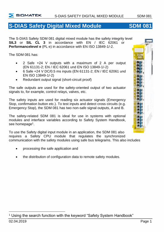
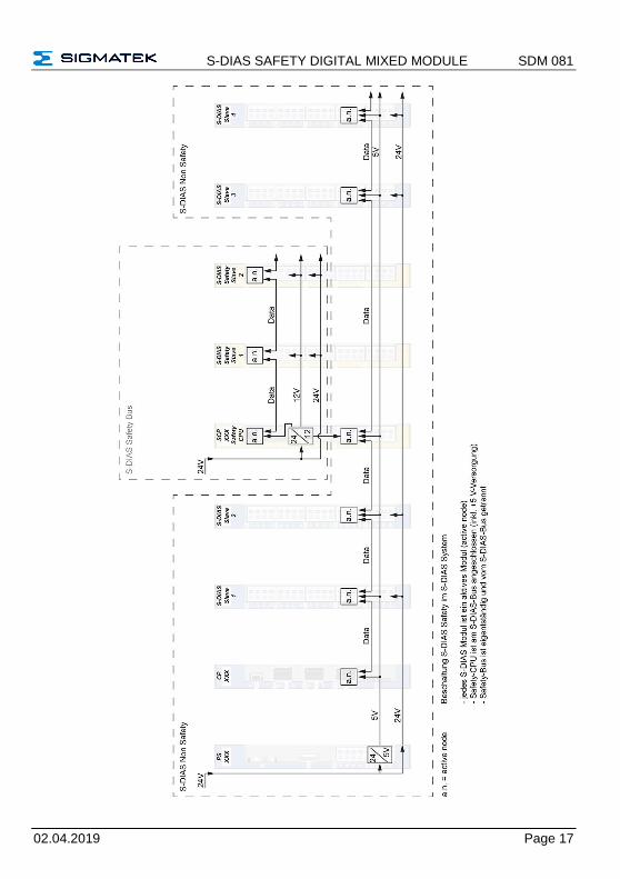
The S-DIAS Safety SDM 081 digital mixed module has the safety integrity level SIL3 or SIL CL 3 in accordance with EN / IEC 62061 or Performancelevel e (PL e) in accordance with EN ISO 13849-1/-2. The SDM 081 has:
• 2 Safe +24 V outputs with a maximum of 2 A per output (EN 61131-2; EN / IEC 62061 und EN ISO 13849-1/-2)
• 6 Safe +24 V DC/0.5 ms inputs (EN 61131-2; EN / IEC 62061 und EN ISO 13849-1/-2)
• Redundant output signal (short-circuit proof) The safe outputs are used for the safety-oriented output of two actuator signals to, for example, control relays, valves, etc. The safety inputs are used for reading six actuator signals (Emergency Stop, confirmation button etc.). To test inputs and detect cross circuits (e.g. Emergency Stop), the SDM 081 has two non-safe signal outputs, A and B. The safety-related SDM 081 is ideal for use in systems with optional modules and interface variables according to Safety System Handbook, see homepage1. To use the Safety digital input module in an application, the SDM 081 also requires a Safety CPU module that regulates the synchronized communication with the safety modules using safe bus telegrams. This also includes
• processing the safe application and
• the distribution of configuration data to remote safety modules.
1 Using the search function with the keyword “Safety System Handbook”
SDM 081 S-DIAS SAFETY DIGITAL MIXED MODULE
Page 2 02.04.2019
Contents
1 Basic Safety Guidelines ......................................................... 4
1.1 General Safety Information .......................................................... 4
1.2 Further Safety Guidelines ............................................................ 5
1.3 General Requirements ................................................................. 6
2 Safety Conformity ................................................................... 9
2.1 Functional Safety Standards ....................................................... 9
2.2 EU Conformity Declaration .......................................................... 9
2.3 Safety-Relevant Parameters ...................................................... 10
2.4 Compatibility ............................................................................... 11
3 Technical Data .......................................................................12
3.1 Input Specifications .................................................................... 12
3.2 Specifications for Cross-Circuit Detection Signal Outputs ... 12
3.3 Input Circuit ................................................................................. 13
3.4 Output Specifications ................................................................. 13
3.4.1 Maximum Inductive Load L (mH) at Load Current I (A) ..................... 14
3.4.2 Maximum Capacitive Load C (µF) at Load Current I (A) .................... 15
3.5 Output Circuit .............................................................................. 16
3.6 Electrical Requirements ............................................................. 16
3.7 Miscellaneous ............................................................................. 18
3.8 Environmental Conditions ......................................................... 18
4 Mechanical Dimensions ........................................................19
S-DIAS SAFETY DIGITAL MIXED MODULE SDM 081
02.04.2019 Page 3
5 Connector Layout .................................................................. 20
5.1 Status LEDs ................................................................................. 21
5.2 Applicable Connectors ............................................................... 21
5.3 Label Field ................................................................................... 22
6 Wiring ..................................................................................... 23
6.1 Wiring Example ........................................................................... 23
6.2 Note .............................................................................................. 24
7 Mounting ................................................................................ 25
8 Disposal ................................................................................. 26
SDM 081 S-DIAS SAFETY DIGITAL MIXED MODULE
Page 4 02.04.2019
1 Basic Safety Guidelines
1.1 General Safety Information
If the safety guidelines are not followed, danger to personnel can arise that could lead to serious injury or in worst cases, death. In less serious cases, systems and equipment can be damaged.
The following symbols identify the individual risks as well as the degree of seriousness; their respective meanings are briefly explained. You should therefore familiarize yourself with the safety symbols and their meanings to prevent dangers and risks.
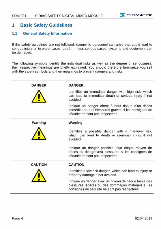
DANGER
DANGER
Identifies an immediate danger with high risk, which can lead to immediate death or serious injury if not avoided.
Indique un danger direct à haut risque d’un décès immédiat ou des blessures graves si les consignes de sécurité ne sont pas respectées.
Warning
Warning
Identifies a possible danger with a mid-level risk, which can lead to death or (serious) injury if not avoided.
Indique un danger possible d’un risque moyen de décès ou de (graves) blessures si les consignes de sécurité ne sont pas respectées.
CAUTION
CAUTION
Identifies a low risk danger, which can lead to injury or property damage if not avoided.
Indique un danger avec un niveau de risque faible des blessures légères ou des dommages matériels si les consignes de sécurité ne sont pas respectées.
S-DIAS SAFETY DIGITAL MIXED MODULE SDM 081
02.04.2019 Page 5
1.2 Further Safety Guidelines
Warning, dangerous electrical voltage
Avertissement d’une tension électrique dangereuse
Hot surface warning
Avertissement d’une surface chaude
Danger for ESD-sensitive components
Les signes de danger pour les composants sensibles aux décharges électrostatiques
This symbol identifies important or additional information regarding the operation of the safety modules.
Ce symbole indique des informations importantes ou supplémentaires concernant le fonctionnement des modules de sécurité particuliers
SDM 081 S-DIAS SAFETY DIGITAL MIXED MODULE
Page 6 02.04.2019
1.3 General Requirements
Technical Documentation
This technical documentation is a component of this product.
• This document must be accessible in the vicinity of the machine, since it contains important instructions.
• The technical documentation should be included in the sale, rental or transfer of the product.
Documentation technique
Cette documentation technique fait partie intégrale du produit.
• Gardez la toujours à portée de main et à la proximité de la machine, car elle contient des informations importantes.
• Distribuez la documentation technique aux secteurs de la vente et/ou de la location du produit.
Prendre connaissance de consignes de sécurité
Avant toute manipulation on doit impérativement prendre connaissance de consignes de sécurité et du mode d’emploi. SIGMATEK GmbH & Co KG n'assume aucune responsabilité pour les dommages causés par le non-respect des consignes de sécurité ou du mode d’emploi respectif. La connaissance de consignes de sécurité et le contenu de cette documentation ainsi que le mode d’emploi du système de sécurité constitue une condition préalable à l'utilisation prévue. Lisez ce mode d’emploi et assurez-vous de le comprendre jusqu’aux détails. Pour plus d'informations sur les normes et les lignes directrices, etc., reportez-vous au mode d’emploi.
Qualified Personnel
Installation, assembly, programming and initial start-up, operation, maintenance and decommissioning of control and automation technology products in general, as well as safety-related products especially, can only be performed by qualified personnel. Qualified personnel in this context are people, who have completed training or have trained under supervision of qualified personnel and have been authorized to operate and maintain safety-related equipment, systems and facilities in compliance with the strict guidelines and standards of safety technology.
S-DIAS SAFETY DIGITAL MIXED MODULE SDM 081
02.04.2019 Page 7
Personnel qualifié
Installation, montage, programmation, mise en service, l'exploitation, l'entretien et mise hors service de produits de commande et d'automatisation en général, et de produits liés à la sécurité, en particulier, ne peut être effectuée que par le personnel qualifié. On entend sous terme personnel qualifié les personnes ayant acquis une formation professionnelle dispensé par un spécialiste sur l’utilisation et surveillance des composants et des systèmes de sécurité, ceci conformément aux lignes directrices et les normes en vigueur.
Designated Use
The Safety modules are designed for use in safety-oriented applications and meet the required conditions for safety operation in compliance with Performancelevel e (PL e), in accordance with EN ISO 13849-1/-2 and SIL3 or SIL CL 3 in accordance with EN 62061. For your own safety and the safety of others, use safety modules for their designated purpose. Correct EMC installation as well as proper transport and storage are also included under designated use. Non-designated use consists of
• any change made to the safety modules of any kind.
• the use of damaged safety modules.
• the use of the safety module outside of the instructions described in this handbook.
• the use of the safety module outside of the technical data described in this handbook.
SDM 081 S-DIAS SAFETY DIGITAL MIXED MODULE
Page 8 02.04.2019
Utilisation prévue
Les modules de sécurité sont conçus pour une utilisation dans les applications sollicitant un niveau de sécurité et répondent à toutes les conditions nécessaires pour un fonctionnement sûr conformément au niveau de performance e (PL e) selon la norme EN ISO 13849-1/-2 et SIL3 ou SIL CL 3 de la norme EN 62061. Utilisez le module de sécurité conformément à son mode d’emploi pour votre propre sécurité et celle d'autres personnes. L'utilisation conforme comprend également une installation conforme CEM ainsi que le transport et le stockage conforme. L'utilisation abusive comprend entre autres:
• Les modifications quelconques apportées aux modules de sécurité.
• Utilisation de modules de sécurité endommagés.
• Utilisation de modules de sécurité en dehors du cadre décrit dans ce mode d’emploi.
• Utilisation de modules de sécurité en dehors des spécifications décrites dans ce mode d’emploi.
Operator Due Diligence
The operator must ensure that
• the Safety modules are to be used for their designated purpose only.
• the Safety modules are to be operated in error-free, fully functional condition only.
• only sufficiently qualified and authorized personnel operate the Safety modules.
• the documentation is complete and in readable condition and available at the site of operation.
Obligation de diligence
L’utilisateur doit s'assurer que
• les modules de sécurité ne sont utilisés que selon les spécifications.
• uniquement les modules de sécurité en parfait état de fonctionnement peuvent être utilisés.
• seulement le personnel qualifié et autorisé puisse manipuler les modules de sécurité.
• la documentation dans son intégralité et dans un état lisible est mise à disposition à l’endroit où les modules de sécurité sont utilisés.
S-DIAS SAFETY DIGITAL MIXED MODULE SDM 081
02.04.2019 Page 9
2 Safety Conformity
2.1 Functional Safety Standards
- EN / IEC 62061:2005/A2:2015 - EN ISO 13849-1:2015 - EN ISO 13849-2:2012
2.2 EU Conformity Declaration
CE Declaration of Conformity
The SDM 081 complies with the following European directives:
• 2006/42/EG “Directive of the European Parliament and of the Council of 17 May 2006 on Machinery and Change to the Directive 95/16/EC” (machine guideline)
• 2014/30/EU “Electromagnetic Compatibility” (EMC guideline)
• 2011/65/EU Restricted use of certain hazardous substances in electrical and electronic equipment (RoHS Guideline)
The EU Conformity Declarations are provided on the SIGMATEK website. Using the search function with the keyword “EU Declaration of Conformity”.
SDM 081 S-DIAS SAFETY DIGITAL MIXED MODULE
Page 10 02.04.2019
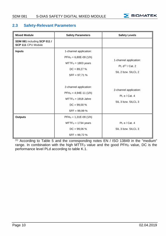
2.3 Safety-Relevant Parameters
Mixed Module Safety Parameters Safety Levels
SDM 081 including SCP 011 /
SCP 111 CPU Module
Inputs 1-channel application:
PFHD = 6,80E-09 (1/h)
MTTFD = 1803 years
DC = 89,27 %
SFF = 97,71 %
2-channel application:
PFHD = 4,94E-11 (1/h)
MTTFD = 1918 Jahre
DC = 99,00 %
SFF = 99,99 %
1-channel application:
PL d(1) / Cat. 2
SIL 2 bzw. SILCL 2
2-channel application:
PL e / Cat. 4
SIL 3 bzw. SILCL 3
Outputs PFHD = 1,31E-09 (1/h)
MTTFD = 1734 years
DC = 99,06 %
SFF = 99,72 %
PL e / Cat. 4
SIL 3 bzw. SILCL 3
(1) According to Table 5 and the corresponding notes EN / ISO 13849 in the "medium" range. In combination with the high MTTFD value and the good PFHD value, DC is the performance level PLd according to table K.1.
S-DIAS SAFETY DIGITAL MIXED MODULE SDM 081
02.04.2019 Page 11
2.4 Compatibility
Compatibility
For compatibility of the S-DIAS Safety modules, see section "Compatibility of S-DIAS Safety Modules" in the system handbook.
Test Signals for Cross-Circuit Detection The module sends pulses in cyclic time intervals to detect a crossed circuit in the outputs. When selecting the actuators, keep in mind that these pulses do not activate the actuators or trigger any diagnostic messages. The pulse signals cannot be deactivated or configured.
Les tests pour la détection de courts-circuits
Le module envoie cycliquement des impulsions afin de détecter un court-circuit sur les sorties. En choisissant les actionneurs assurez-vous que ces impulsions ne provoquent ni une commutation d'un actionneur ni l’apparition d’un message de diagnostic. Les impulsions ne peuvent être ni désactivées ni configurées.
Contact Short Detection
It is important to keep in mind that the cross-circuit detection only functions correctly when it is configured and wired correctly. This applies equally to in- and outputs.
Détection de courts-circuits
Il est important de noter que la détection de courts-circuits dans le contexte des fonctionnalités de sécurité ne fonctionne que si elle a été correctement câblée et configurée. Cela vaut aussi bien pour les entrées que pour les sorties.
SDM 081 S-DIAS SAFETY DIGITAL MIXED MODULE
Page 12 02.04.2019
3 Technical Data
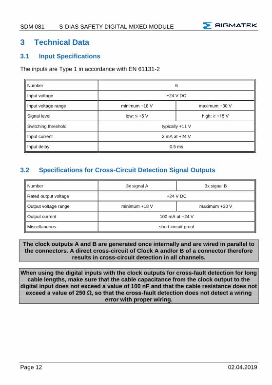
3.1 Input Specifications
The inputs are Type 1 in accordance with EN 61131-2
Number 6
Input voltage +24 V DC
Input voltage range minimum +18 V maximum +30 V
Signal level low: ≤ +5 V high: ≥ +15 V
Switching threshold typically +11 V
Input current 3 mA at +24 V
Input delay 0.5 ms
3.2 Specifications for Cross-Circuit Detection Signal Outputs
Number 3x signal A 3x signal B
Rated output voltage +24 V DC
Output voltage range minimum +18 V maximum +30 V
Output current 100 mA at +24 V
Miscellaneous short-circuit proof
The clock outputs A and B are generated once internally and are wired in parallel to the connectors. A direct cross-circuit of Clock A and/or B of a connector therefore
results in cross-circuit detection in all channels.
When using the digital inputs with the clock outputs for cross-fault detection for long cable lengths, make sure that the cable capacitance from the clock output to the
digital input does not exceed a value of 100 nF and that the cable resistance does not exceed a value of 250 Ω, so that the cross-fault detection does not detect a wiring
error with proper wiring.
S-DIAS SAFETY DIGITAL MIXED MODULE SDM 081
02.04.2019 Page 13
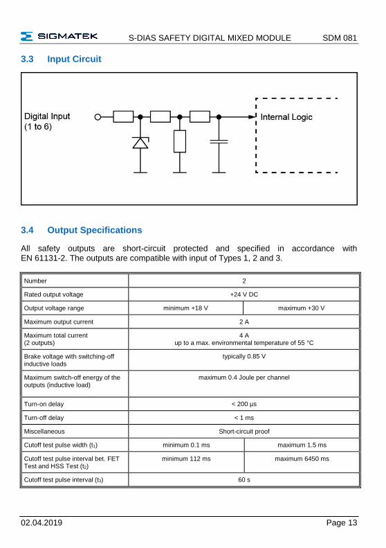
3.3 Input Circuit
3.4 Output Specifications
All safety outputs are short-circuit protected and specified in accordance with EN 61131-2. The outputs are compatible with input of Types 1, 2 and 3.
Number 2
Rated output voltage +24 V DC
Output voltage range minimum +18 V maximum +30 V
Maximum output current 2 A
Maximum total current (2 outputs)
4 A up to a max. environmental temperature of 55 °C
Brake voltage with switching-off inductive loads
typically 0.85 V
Maximum switch-off energy of the outputs (inductive load)
maximum 0.4 Joule per channel
Turn-on delay < 200 µs
Turn-off delay < 1 ms
Miscellaneous Short-circuit proof
Cutoff test pulse width (t1) minimum 0.1 ms maximum 1.5 ms
Cutoff test pulse interval bet. FET Test and HSS Test (t2)
minimum 112 ms maximum 6450 ms
Cutoff test pulse interval (t3) 60 s
SDM 081 S-DIAS SAFETY DIGITAL MIXED MODULE
Page 14 02.04.2019
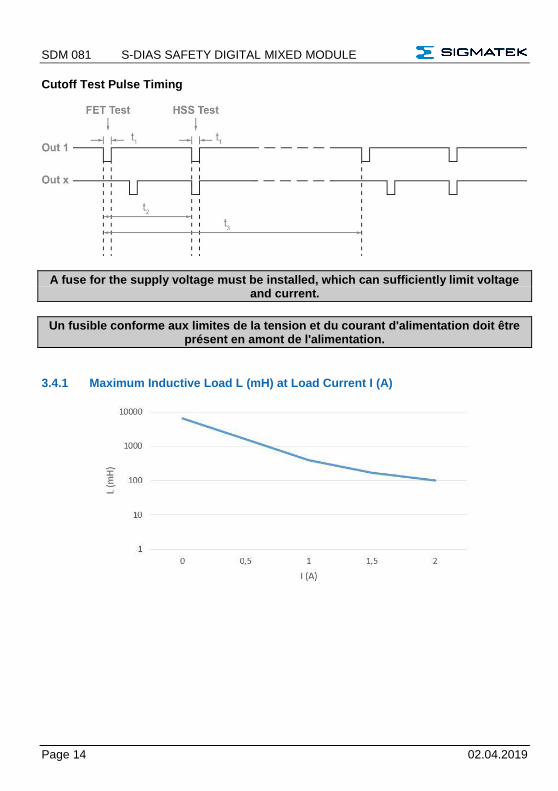
Cutoff Test Pulse Timing
A fuse for the supply voltage must be installed, which can sufficiently limit voltage and current.
Un fusible conforme aux limites de la tension et du courant d'alimentation doit être présent en amont de l'alimentation.
3.4.1 Maximum Inductive Load L (mH) at Load Current I (A)
S-DIAS SAFETY DIGITAL MIXED MODULE SDM 081
02.04.2019 Page 15
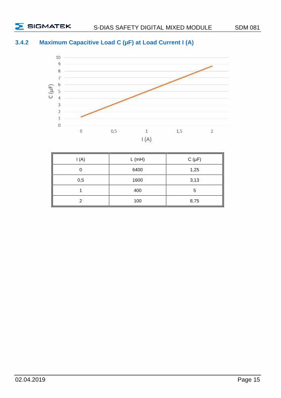
3.4.2 Maximum Capacitive Load C (µF) at Load Current I (A)
I (A) L (mH) C (µF)
0 6400 1,25
0,5 1600 3,13
1 400 5
2 100 8,75
SDM 081 S-DIAS SAFETY DIGITAL MIXED MODULE
Page 16 02.04.2019
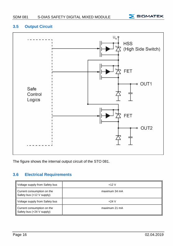
3.5 Output Circuit
The figure shows the internal output circuit of the STO 081.
3.6 Electrical Requirements
Voltage supply from Safety bus +12 V
Current consumption on the
Safety bus (+12 V supply)
maximum 34 mA
Voltage supply from Safety bus +24 V
Current consumption on the
Safety bus (+24 V supply)
maximum 21 mA
S-DIAS SAFETY DIGITAL MIXED MODULE SDM 081
02.04.2019 Page 17
SDM 081 S-DIAS SAFETY DIGITAL MIXED MODULE
Page 18 02.04.2019
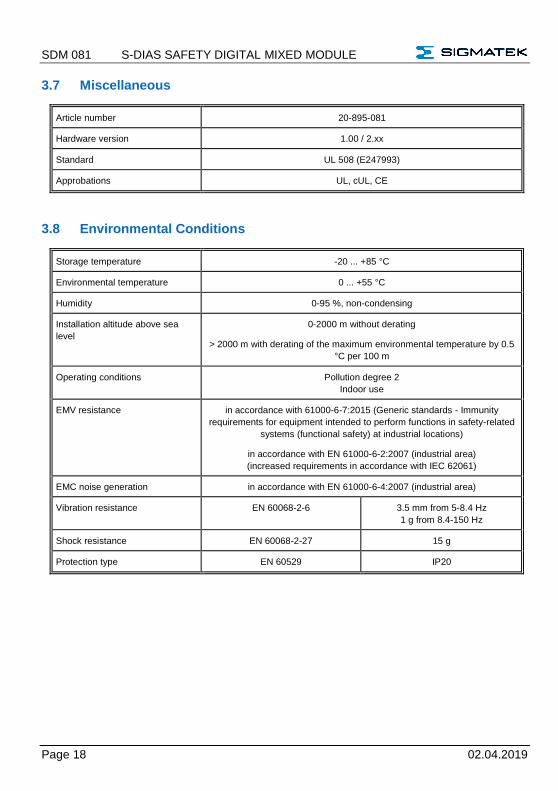
3.7 Miscellaneous
Article number 20-895-081
Hardware version 1.00 / 2.xx
Standard UL 508 (E247993)
Approbations UL, cUL, CE
3.8 Environmental Conditions
Storage temperature -20 ... +85 °C
Environmental temperature 0 ... +55 °C
Humidity 0-95 %, non-condensing
Installation altitude above sea
level
0-2000 m without derating
> 2000 m with derating of the maximum environmental temperature by 0.5
°C per 100 m
Operating conditions Pollution degree 2
Indoor use
EMV resistance in accordance with 61000-6-7:2015 (Generic standards - Immunity
requirements for equipment intended to perform functions in safety-related
systems (functional safety) at industrial locations)
in accordance with EN 61000-6-2:2007 (industrial area)
(increased requirements in accordance with IEC 62061)
EMC noise generation in accordance with EN 61000-6-4:2007 (industrial area)
Vibration resistance EN 60068-2-6 3.5 mm from 5-8.4 Hz
1 g from 8.4-150 Hz
Shock resistance EN 60068-2-27 15 g
Protection type EN 60529 IP20
S-DIAS SAFETY DIGITAL MIXED MODULE SDM 081
02.04.2019 Page 19
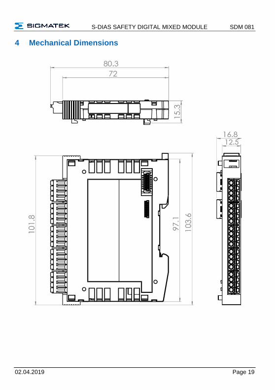
4 Mechanical Dimensions
SDM 081 S-DIAS SAFETY DIGITAL MIXED MODULE
Page 20 02.04.2019
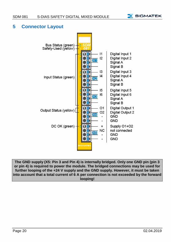
5 Connector Layout
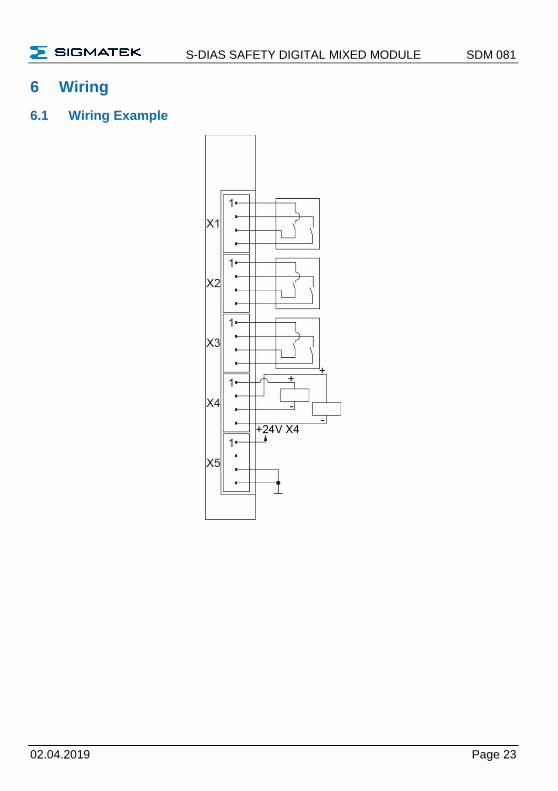
The GND supply (X5: Pin 3 and Pin 4) is internally bridged. Only one GND pin (pin 3 or pin 4) is required to power the module. The bridged connections may be used for further looping of the +24 V supply and the GND supply. However, it must be taken
into account that a total current of 6 A per connection is not exceeded by the forward looping!
S-DIAS SAFETY DIGITAL MIXED MODULE SDM 081
02.04.2019 Page 21
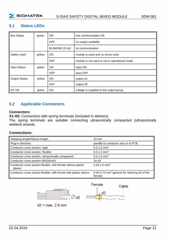
5.1 Status LEDs
Bus Status green ON bus communication OK
OFF no supply available
BLINKING (5 Hz) no communication
Safety Used yellow ON module is used and no errors exist
OFF module is not used or not in operational mode
Input Status green ON input ON
OFF input OFF
Output Status yellow ON output on
OFF output off
DC OK green ON voltage is supplied to the output group
5.2 Applicable Connectors
Connectors: X1-X5: Connectors with spring terminals (included in delivery) The spring terminals are suitable connecting ultrasonically compacted (ultrasonically welded) strands. Connections:
Stripping length/Sleeve length: 10 mm
Plug-in direction: parallel to conductor axis or to PCB
Conductor cross section, rigid: 0.2-1.5 mm2
Conductor cross section, flexible: 0.2-1.5 mm2
Conductor cross section, ultrasonically compacted: 0.2-1.5 mm2
Conductor cross section AWG/kcmil: 24-16
Conductor cross section flexible, with ferrule without plastic sleeve:
0.25-1.5 mm2
Conductor cross section flexible, with ferrule with plastic sleeve: 0.25-0.75 mm2 (ground for reducing d2 of the ferrule)
SDM 081 S-DIAS SAFETY DIGITAL MIXED MODULE
Page 22 02.04.2019
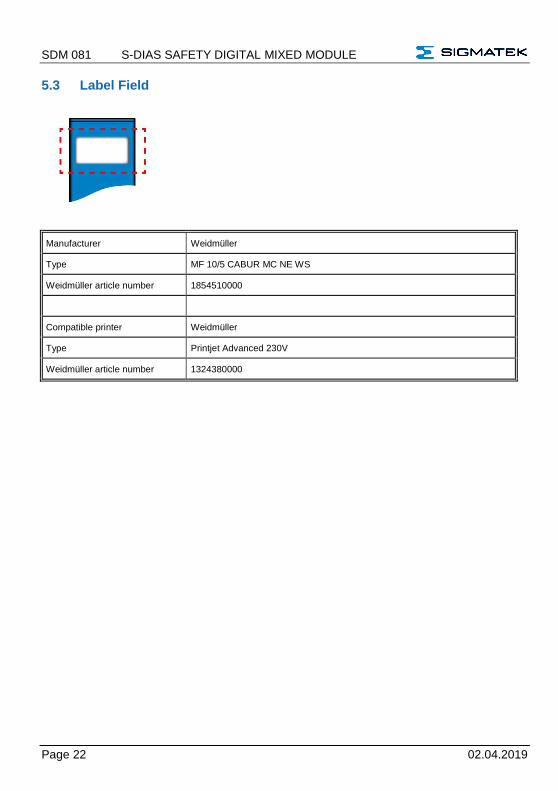
5.3 Label Field
Manufacturer Weidmüller
Type MF 10/5 CABUR MC NE WS
Weidmüller article number 1854510000
Compatible printer Weidmüller
Type Printjet Advanced 230V
Weidmüller article number 1324380000
S-DIAS SAFETY DIGITAL MIXED MODULE SDM 081
02.04.2019 Page 23
6 Wiring
6.1 Wiring Example
SDM 081 S-DIAS SAFETY DIGITAL MIXED MODULE
Page 24 02.04.2019
6.2 Note
The input filters, which suppress noise signals, allow operation in harsh environmental conditions. A careful wiring method is also recommended to ensure error-free function.
The following installation guidelines should be observed:
• avoid parallel connections between input lines and load-bearing circuits.
• protective circuits for all relays (RC networks or free-wheeling diodes)
• correct wiring to ground
The ground bus should be connected to the control cabinet when possible!
Si possible la terre doit être connectée à l'armoire de commande!
Wiring and mounting must be performed with no voltage applied!
Le câblage et l'installation ne doivent être effectués que sur un système hors tension !
IMPORTANT: The S-DIAS module CANNOT be connected or disconnected while voltage is applied!
IMPORTANT: Le module S-Dias NE PEUT PAS être inséré ou retiré sous tension.
S-DIAS SAFETY DIGITAL MIXED MODULE SDM 081
02.04.2019 Page 25
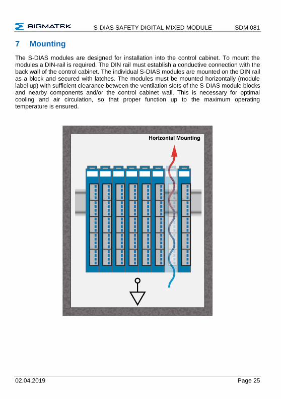
7 Mounting
The S-DIAS modules are designed for installation into the control cabinet. To mount the modules a DIN-rail is required. The DIN rail must establish a conductive connection with the back wall of the control cabinet. The individual S-DIAS modules are mounted on the DIN rail as a block and secured with latches. The modules must be mounted horizontally (module label up) with sufficient clearance between the ventilation slots of the S-DIAS module blocks and nearby components and/or the control cabinet wall. This is necessary for optimal cooling and air circulation, so that proper function up to the maximum operating temperature is ensured.
SDM 081 S-DIAS SAFETY DIGITAL MIXED MODULE
Page 26 02.04.2019
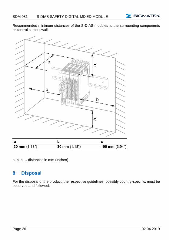
Recommended minimum distances of the S-DIAS modules to the surrounding components or control cabinet wall:
a, b, c … distances in mm (inches)
8 Disposal
For the disposal of the product, the respective guidelines, possibly country-specific, must be observed and followed.
S-DIAS SAFETY DIGITAL MIXED MODULE SDM 081
02.04.2019 Page 27
Documentation Changes
Change date Affected
page(s)
Chapter Note
18.07.2014 17 5 Connector Layout Added wiring notice
08.09.2014 15 3.8 Miscellaneous Added Standard
30.01.2015 20 6.2 Note Added note concerning connecting the S-DIAS
module while voltage is applied
26.03.2015 18 5.2 Applicable Connectors Added connections
07.05.2015 New writing: EN ISO 13849-1/-2
18.05.2015 15 3.9 Environmental Conditions Expanded vibration resistance
08.07.2015 13 3.7 Output Specifications Added mnemotechnic verse
04.08.2015 Info Cover Translation from German added
28.08.2015 15 5 Connector Layout Changed Notice in grey box
17.02.2016 13 3.4 Switching-off inductive loads
18.02.2016 16 5 Connector Layout Graphics changed
28.04.2016 24 7 Mounting Graphics distances
13.03.2017 12 3.2 Signal Output
Specifications for Cross-
Circuit Detection
Note added
15.05.2017 14 3.4.1 Maximum Inductive
Load L (mH) at Load Current
I (A)
3.4.2 Maximum Capacitive
Load C (µF) at Load Current I
(A)
Chapter added
Chapter added
17.08.2017 17
20
3.8 Environmental Conditions
5.2 Applicable Connectors
Pollution Degree
Sleeve length added
Added info regarding ultrasonically welded strands
23.08.2017 13 3.4 Output Specifications Table expanded, Cutoff Test Pulse Timing added
30.08.2017 13 3.1 Output Specifications Cutoff Test Pulse Timing
18.10.2017 22
26
5.3 Label Field
7 Mounting
Added chapter
Graphic replaced
20.09.2018 5 Connector Layout Note added
SDM 081 S-DIAS SAFETY DIGITAL MIXED MODULE
Page 28 02.04.2019
05.10.2018 3.2 Specifications for Cross-
Circuit Detection Signal
Outputs
Note for cable capacitance and for cable resistance
added
02.04.2019 11
19
all
2.3 Safety-Relevant
Parameters
3.8 Environmental Conditions
Correction of the safety-relevant parameters
Corrections environmental conditions
Corrections due to CE
Top Related