


Languages
Pages
Legal


SCC 1500D

1
SANY CRAWLER CRANE SCC1500D
1
SCC1500Dcontent
P2
P12
P21
SCC1500D Crawler CraneOutline Dimensions
Main Technical FeaturesMain Performance Data
Transport DimensionsAssembly Diagram
Specifi cationsSuperstructureUndercarriage Operation Devices Safety DevicesTable of Main Mechanism Data
Operating Condition CombinationOperating Condition Combination
HL Operating Condition of Light-duty BoomFixed Jib Opertation Condition
02 Outline Dimensions03 Main Technical Features04 Main Performance Data05 Transport Dimensions09 Assembly Diagram
CRAWLER CRANE

SANY CRAWLER CRANE SCC1500D
3 2
Main Technical FeaturesOUTLINE dimensions
1. Safety control system:Two convenient and reliable modes of operation; working and installation, with real-time level display, stop operation braking away from machine, electrical emergency control,anti-lightning protection, automatically walk switches, CCTV monitoring function, complete safety and supervision system;
2. Excellent operating performance:Load-sensing, limit load regulation and electro-hydraulic proportional micro-speed control make each inching performance extremely good and operation more stable;
3. Reliable functions assurance:Sufficient safety margin for structural and mechanical design; control system can operate stably in harsh environments such as cold, high temperature, altitude and sandy conditions;
4. Convenient maintenance technology:It takes approximately no more than 10min/person to adjust;no more than 30min/person for daily maintenance;no more than 2h/person to repair.GPS remote monitoring system is optional for maintenance and management;
5. Powerful lifting capacity:The maximum lifting capacity of boom is 112.5t*8m=900tm, the longest main boom81m;
6. Efficient self assembly and disassembly technology:
The whole machine can be assembled and disassembled by itself, and the assembly of basic machine only requires 3h; the patented synchronic control technology of one-key lifted mast has independent intellectual property right;
7. Optimized transportation program: The transportation width of basic machine is only 3m, with a transportation weight of 43.5t, so it can be transported around the world without limitation;
8. Large-Chassis design:Track frame which can be broadened, ensuring excellent machine and job stability within the range of 360 degree rotation with a gauge of 6m;
9. Automatic traveling direction:The crane may travel forward through automatic adjustment after slewing 180o;
10. Fuel heater (optional):Able to satify low temperature igniation in extremely cold areas;
11. Two-stage filter of engine: Enable the use of domestic diesel engine;
12. 100% load travel:Powerful tracking force and travel smoothness bring the advantages of crawler crane into full play;
13. Broad adaptability:Meet certification requirements of CE, North America, Australia, Russia and Taiwan; the engine emission complies with the European and U.S. Non-highway Stage 3 Standards.
B
B
R6426
7100
A
A
10540
8631

SANY CRAWLER CRANE SCC1500D
5 4
Transport DimensionsMain Performance Data
Main Performance Data Of Scc1500d Crawler Crane
Performance index Unit Data
Boom Operating Condition
Max. rated lifting capacity t 150
Max. rated lifting moment t·m 112.5t×8
Boom Length m 18~81
Boom Luffing Angle ° 30~80
Fixed jib Operating Condition
Fully extended boom+fully extended fixed jib m (69+31)/(75+13)
Angle between boom and jib ° 15,30
Speed parameter
Rope speed of main (auxiliary) winch (at outermost working layer)
m/min 0~125
Rope speed of main luffing winch (at outermost working layer)
m/min (0~24)×2
Swing speed rpm 0~2
Traveling Speed km/h0~1.2/0~0.6(two options )
Gradeability % 30
Engine Output power/rated engine speed kW/ rpm 242 /2100
Transportation parameter
Maximum transport weight of single part piece t 43.5
Transportation dimension (length x width x height) mm 10130×3000×3200
OtherAverage ground bearing pressure MPa 0.09
Max gradeability % 30
Basic Machine ×1
Length 10.13m
Width 3.00m
Height 3.20m
Weight 43.5t
Track Frame ×2
Length 8.63m
Width 1.34m
Height 1.29m
Weight 20t
Boom Tip ×1
Length 10.91m
Width 2.21m
Height 2.31m
Weight 2.8t
Boom Base ×1
Length 8.07m
Width 2.23m
Height 2.91m
Weight 4.4t
3m Boom Insert ×1
Length 3.13m
Width 2.23m
Height 2.01m
Weight 0.81t
6m Boom Insert ×2
Length 6.14m
Width 2.30m
Height 2.01m
Weight 1.3tL
H
L
H
L
H
L
HW
L
L
H
SANY CRAWLER CRANE SCC1500D
7 6
Transport DimensionsTransport Dimensions
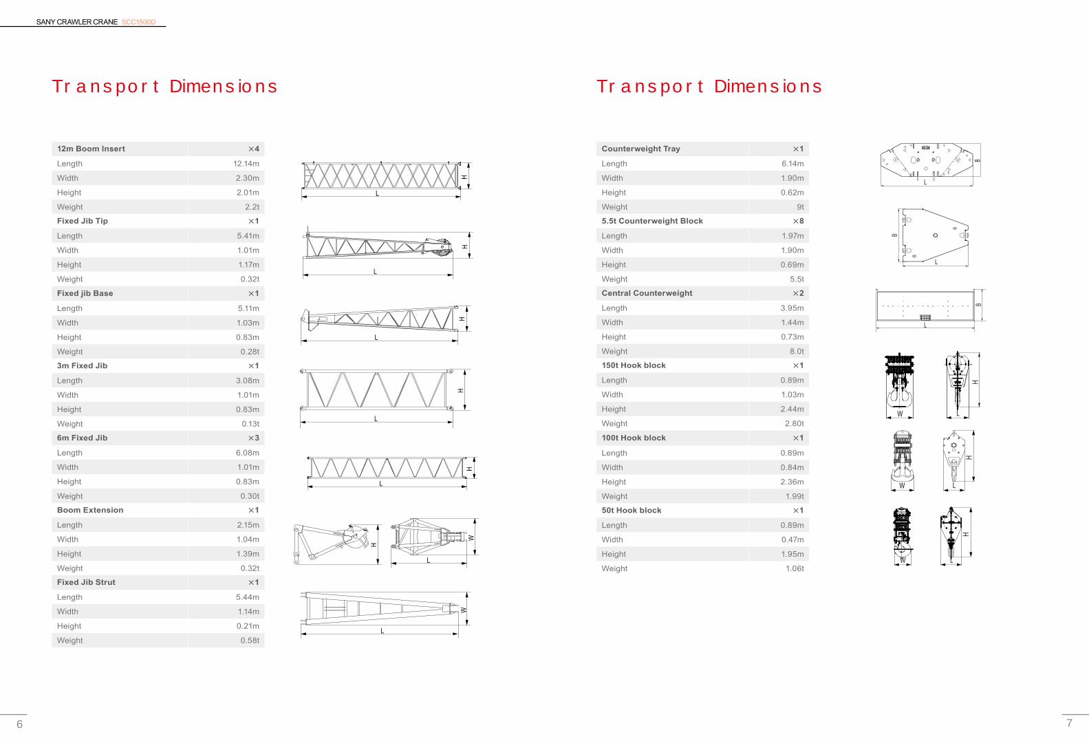
12m Boom Insert ×4
Length 12.14m
Width 2.30m
Height 2.01m
Weight 2.2t
Fixed Jib Tip ×1
Length 5.41m
Width 1.01m
Height 1.17m
Weight 0.32t
Fixed jib Base ×1
Length 5.11m
Width 1.03m
Height 0.83m
Weight 0.28t
3m Fixed Jib ×1
Length 3.08m
Width 1.01m
Height 0.83m
Weight 0.13t
6m Fixed Jib ×3
Length 6.08m
Width 1.01m
Height 0.83m
Weight 0.30t
Boom Extension ×1
Length 2.15m
Width 1.04m
Height 1.39m
Weight 0.32t
Fixed Jib Strut ×1
Length 5.44m
Width 1.14m
Height 0.21m
Weight 0.58t
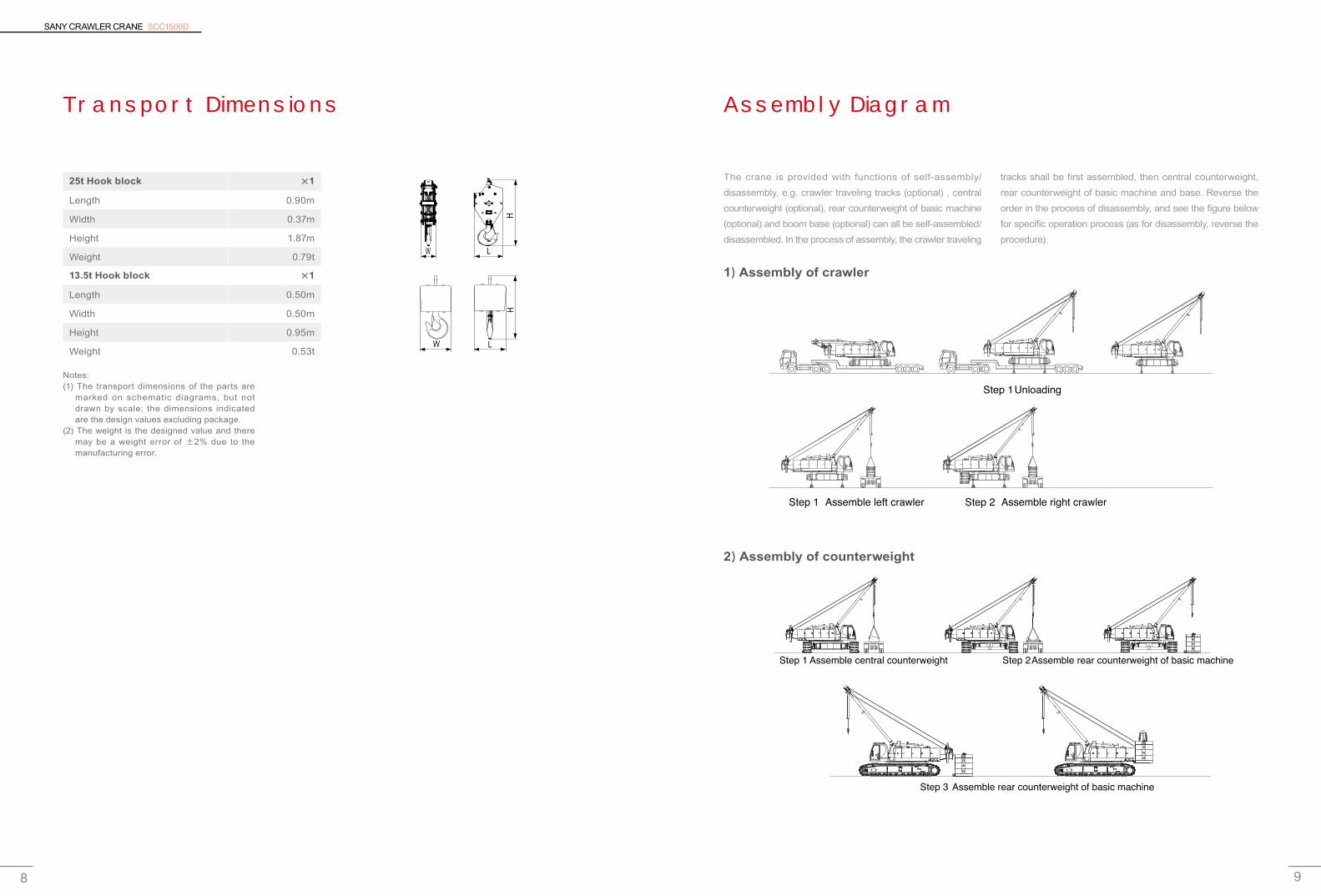
Counterweight Tray ×1
Length 6.14m
Width 1.90m
Height 0.62m
Weight 9t
5.5t Counterweight Block ×8
Length 1.97m
Width 1.90m
Height 0.69m
Weight 5.5t
Central Counterweight ×2
Length 3.95m
Width 1.44m
Height 0.73m
Weight 8.0t
150t Hook block ×1
Length 0.89m
Width 1.03m
Height 2.44m
Weight 2.80t
100t Hook block ×1
Length 0.89m
Width 0.84m
Height 2.36m
Weight 1.99t
50t Hook block ×1
Length 0.89m
Width 0.47m
Height 1.95m
Weight 1.06t
H
L
L
L
L
L
WH
HH
H
L
H
L
W
L
H
W
L
H
W
W L
H
L
L
L
B
B
B
SANY CRAWLER CRANE SCC1500D
9 8
Transport Dimensions Assembly Diagram
Notes:(1) The transport dimensions of the parts are
marked on schematic diagrams, but not drawn by scale; the dimensions indicated are the design values excluding package.
(2) The weight is the designed value and there may be a weight error of ±2% due to the manufacturing error.
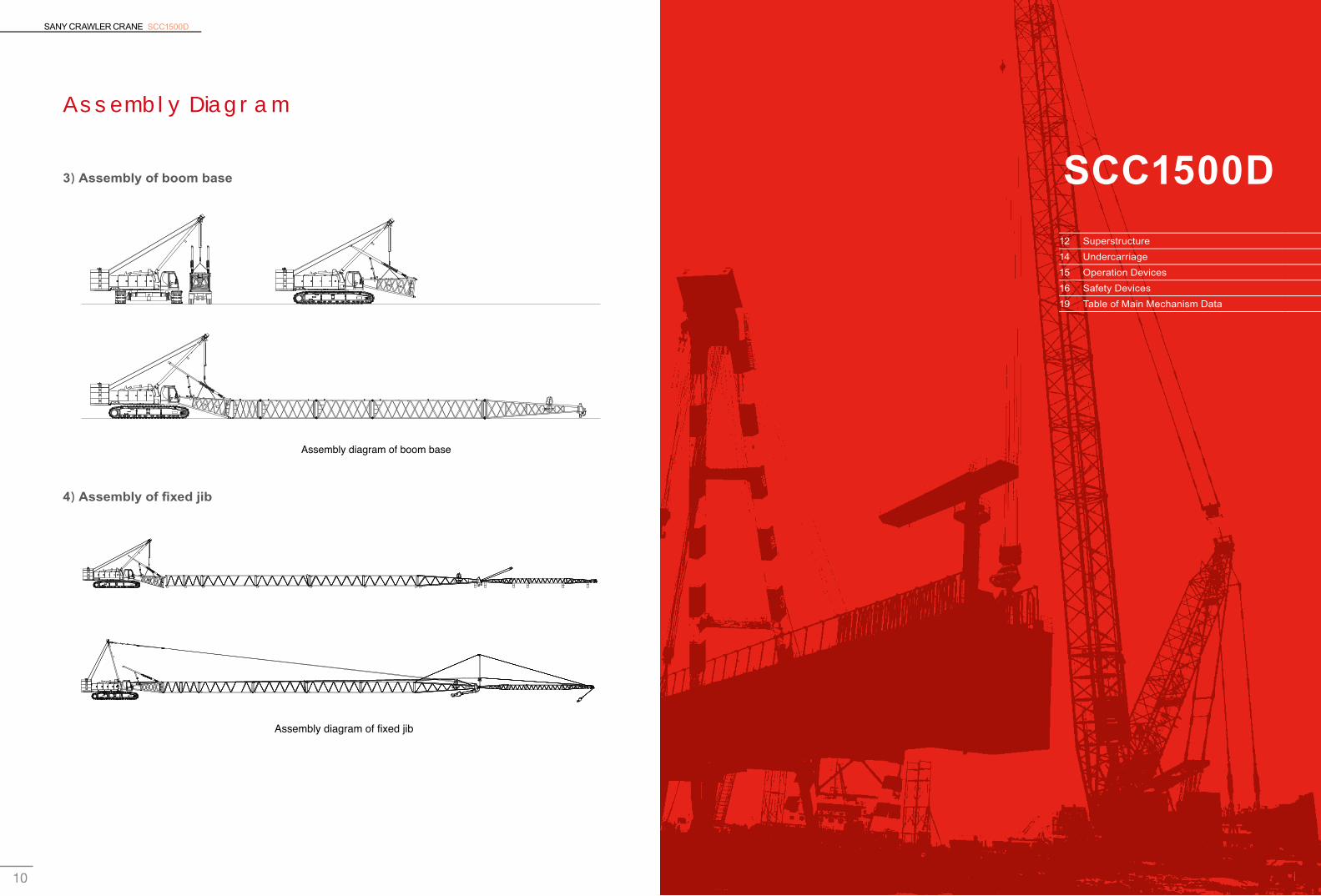
The crane is provided with functions of self-assembly/disassembly, e.g. crawler traveling tracks (optional) , central counterweight (optional), rear counterweight of basic machine (optional) and boom base (optional) can all be self-assembled/disassembled. In the process of assembly, the crawler traveling
1)Assembly of crawler
2)Assembly of counterweight
25t Hook block ×1
Length 0.90m
Width 0.37m
Height 1.87m
Weight 0.79t
13.5t Hook block ×1
Length 0.50m
Width 0.50m
Height 0.95m
Weight 0.53tW L
H
W L
H
tracks shall be first assembled, then central counterweight, rear counterweight of basic machine and base. Reverse the order in the process of disassembly, and see the figure below for specific operation process (as for disassembly, reverse the procedure).
Step 1Unloading
Step 1 Assemble left crawler Step 2 Assemble right crawler
Step 1 Assemble central counterweight Step 2Assemble rear counterweight of basic machine
Step 3 Assemble rear counterweight of basic machine
SANY CRAWLER CRANE SCC1500D
11 10 11
SCC1500D
Assembly Diagram
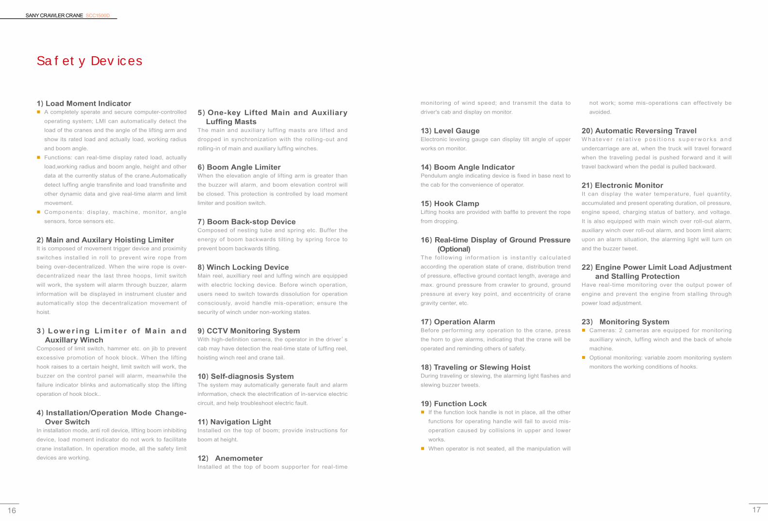
3)Assembly of boom base
4)Assembly of fi xed jib
Assembly diagram of boom base
Assembly diagram of fixed jib
12 Superstructure14 Undercarriage 15 Operation Devices16 Safety Devices19 Table of Main Mechanism Data

SANY CRAWLER CRANE SCC1500D
13 12
NO.1 Main hoisting winch
Drum diameter 596mm
Rope speed of the outermost working layer 0~125m/min
Wire rope diameter 26mm
Wire rope length of main winch 350m
Rated single rope pull force line pull 13.4t
Specification Right-rotary concurrent twist
NO.2 Auxiliary hoisting
Drum diameter 596mm
Rope speed of the outermost working layer 0~125m/min
Wire rope diameter 26mm
Wire rope length of auxiliary winch 300m
Rated single rope pull force line pull 13.4t
Specification Right-rotaryconcurrent twist
Superstructure
1)Engine ■ American Cummins:
Rated power/speed: 242kW/2100rpm.Maximum torque: 1424N·m/1500rpm.Emission standards: Tier 3.
■ Dongfeng Cummins:Rated power/speed: 242kW/2100rpm.Maximum torque: 1385N·m/1500rpm.Emission standards: Tier 3.
■ Air filter: double filtration system compose of air pre-filter and air filter.
■ Fuel tank: 400L with fuel indicator and digital display
2)Hydraulic System ■ Configuration of hydraulic system: Advanced hydraulic
system, including the main pump, main valve, control handle and motor reducer. It is ef f icient, energy saving, stable and reliable.
■ It has excellent micro-rotation and per formance improvement, load sensing; limit load regulation makes the operation more stable.
■ Adopt contro l led hydraul ic o i l cool ing system independently.
3)Main and Auxiliary Hoisting Mechanisms ■ The main and auxiliary winches are separately driven
and are easy to assemble with their concise structure; the maintenance-free, built-in wet brake, boasting low abrasion, ensures the safety of winches.
■ The variable hydraulic motor achieves max. winch speed by adjusting the displacement automatically according to load.
■ High-quality non-rotating wire rope is selected to secure high hoisting safety and long service life.
4)Swing Mechanism ■ Driven by swing motor and hydraulically buffered it
may provide 360°. ■ Brake: Built-in, wet, spring-loaded normal-engaged
disk brake applies braking through spring force and release braking through oil pressure.
■ Lock: A locking device is provided to protect the upper slewing from impact during hoisting transportation.
■ Swing ring: Triple-row roller slewing ring. ■ Swing speed: 0~2.0r/min.
NO.3 Main luffing winch
Drum diameter 460mm
Rope speed of the outermost working layer (0~24)×2 m/min
Wire rope diameter 20mm
Wire rope length of main luffing winch 320m
Rated single rope pull force line pull 9.73t
Specification of wire rope Right-rotary alternating twist
Name Q’ty Single piece weight(kg) Weight (kg)
Counterweight block 8 5500 44000
Counterweigh tray 1 9000 9000
Central counterweight 2 8000 16000
Total weight of all counterweights (kg) 69000
5)Main And Auxiliary Luffing MechanismsThe main luffing mechanism adopts tandem Drum.
6)Cab ■ Unique SANY-style and all-closed driver’s cab in
the latest design, with wide vision, is equipped with adjustable seat, and heating and cooling air conditioner.
■ Four head lights provide illumination for far and near distances.
■ Large glass window with rearview mirror makes the field of vision broader .
■ Armrest box may be adjusted forward and backward with the seat, comfortable to operate, and it complies with ergonomic principle in a more desirable way.
■ The driver’s cab can be adjusted according to the operating needs, capable of realizing 20° pitching.
■ upward or downward, and it can be rotated to the right front of platform.
■ The pitching cab broadens the operation vision of the driver , thus improving the safety in operation; it can be rotated and thus reduces the transportation width.
7)Control Operation ■ All actions of the crawler travel unit are controlled by the
traveling pedal (control lever). The left traveling pedal (control lever) drives the left crawler while the right traveling pedal (control lever) drives the right crawler. The engine speed is controlled by the foot throttle or hand throttle and the start switch is located on the right armrest box. The control handles of main luffing and main winch are located on the right armrest box while the control handles of auxiliary winch, auxiliary luffing/slewing control handles on the left armrest box. To the right front of seat is the auxiliary control box, on the control panel of which all switches are operated manually to realize corresponding functions.
■ The operation of traveling pedal (control lever) has the function of automatic direction adjustment, that is, the operation direction is always the front direction of the operator.
6)Counterweight

SANY CRAWLER CRANE SCC1500D
15 14
Undercarriage
1)Crawler Travel All crawler frames are equipped with independent traveling drive. The hydraulic traveling motor drives planet gear reducer to achieve independent traveling through the transmission of the driving wheel.
2)Travel BrakeThe travel brake is a disk brake normally engaged in the reducer, that is, the brake is in the braking state when the operation pedal valve is not pushed down; and it is capable of automatic compensation, free of adjustment. When the operation pedal valve is pushed down, the brake will be released to realize traveling.
3)Crawler ShoesThe crawler units at the left and right have 112 crawler shoes totally, each 1,100mm wide. The tensity of crawler shoe can be adjusted via the hydraulic jack, and an ideal tensity can be achieved through adjusting the position of adjusting gasket.
4)Chassis ■ The hydraulic cyl inder dr ives the power pin to
connect with crawler frame, easy for assembly and disassembly. A frame structure welded with high-strength steel.
■ The large chassis design obviously improves the stability of the whole machine.
■ Counterweights of undercarr iage weigh 16t, 8t respectively at the front and back, and they can be self assembled/disassembled.
5)Travel Speed ■ Low speed: 0.6 km/h ■ High speed: 1.2 km/h
Operation DeviceS
1)Boom ■ Lattice structures; the main chord adopts high
strength structure steel; each section is connected with pins.
■ Basic boom: 10.5m tip +7.5m base boom insert: 3m×1,6m× 2, 12m×4.
■ Boom Length: 18m~ 81m.
2)Fix Jib ■ Lattice structures; the main chord adopts high strength
structure steel; each section is connected with pins: Basic boom 5m tip +5m base boom insert: 3m× 1, 6m×3.
■ Jib Length: 13m~ 31m.
■ The longest Boom + Jib = 69m + 31m/ 75m + 13m.
3)Boom extensionAll in welded structure, the arm has one pulley on head and is connected to the upper part of the boom with a pin roll.
4)Lifting Hook ■ Standard configuration: 150t hook block
50t hook block13.5t hook block
■ Optional configuration: 25t hook block100t hook block
Note: The operation devices are safe configuration ; order contract shall prevail for specific configuration.
SANY CRAWLER CRANE SCC1500D
17 16
Safety Devices
1)Load Moment Indicator ■ A completely sperate and secure computer-controlled
operating system; LMI can automatically detect the load of the cranes and the angle of the lifting arm and show its rated load and actually load, working radius and boom angle.
■ Functions: can real-time display rated load, actually load,working radius and boom angle, height and other data at the currently status of the crane.Automatically detect luffing angle transfinite and load transfinite and other dynamic data and give real-time alarm and limit movement.
■ Components: display, machine, monitor, angle sensors, force sensors etc.
2)Main and Auxilary Hoisting LimiterIt is composed of movement trigger device and proximity switches installed in roll to prevent wire rope from being over-decentralized. When the wire rope is over-decentralized near the last three hoops, limit switch will work, the system will alarm through buzzer, alarm information will be displayed in instrument cluster and automatically stop the decentralization movement of hoist.
3)Lower ing L imi t e r o f M a in and Auxillary Winch
Composed of limit switch, hammer etc. on jib to prevent excessive promotion of hook block. When the lifting hook raises to a certain height, limit switch will work, the buzzer on the control panel will alarm, meanwhile the failure indicator blinks and automatically stop the lifting operation of hook block..
4)Installation/Operation Mode Change-Over Switch
In installation mode, anti roll device, lifting boom inhibiting device, load moment indicator do not work to facilitate crane installation. In operation mode, all the safety limit devices are working.
5)One-key Lifted Main and Auxiliary Luffing Masts
The main and auxiliary luf f ing masts are lif ted and dropped in synchronization with the rolling-out and rolling-in of main and auxiliary luffing winches.
6)Boom Angle LimiterWhen the elevation angle of lifting arm is greater than the buzzer will alarm, and boom elevation control will be closed. This protection is controlled by load moment limiter and position switch.
7)Boom Back-stop DeviceComposed of nesting tube and spring etc. Buffer the energy of boom backwards tilting by spring force to prevent boom backwards tilting.
8)Winch Locking Device Main reel, auxilliary reel and luffing winch are equipped with electric locking device. Before winch operation, users need to switch towards dissolution for operation consciously, avoid handle mis-operation; ensure the security of winch under non-working states.
9)CCTV Monitoring SystemWith high-definition camera, the operator in the driver’s cab may have detection the real-time state of luffing reel, hoisting winch reel and crane tail.
10)Self-diagnosis SystemThe system may automatically generate fault and alarm information, check the electrification of in-service electric circuit, and help troubleshoot electric fault.
11)Navigation LightInstalled on the top of boom; provide instructions for boom at height.
12) Anemometer Installed at the top of boom supporter for real-time
monitoring of wind speed; and transmit the data to driver's cab and display on monitor.
13)Level GaugeElectronic leveling gauge can display tilt angle of upper works on monitor.
14)Boom Angle IndicatorPendulum angle indicating device is fixed in base next to the cab for the convenience of operator.
15)Hook ClampLifting hooks are provided with baffle to prevent the rope from dropping.
16)Real-time Display of Ground Pressure (Optional)
The fol lowing informat ion is instant ly calculated according the operation state of crane, distribution trend of pressure, effective ground contact length, average and max. ground pressure from crawler to ground, ground pressure at every key point, and eccentricity of crane gravity center, etc.
17)Operation Alarm Before performing any operation to the crane, press the horn to give alarms, indicating that the crane will be operated and reminding others of safety.
18)Traveling or Slewing HoistDuring traveling or slewing, the alarming light flashes and slewing buzzer tweets.
19)Function Lock ■ If the function lock handle is not in place, all the other
functions for operating handle will fail to avoid mis-operation caused by collisions in upper and lower works.
■ When operator is not seated, all the manipulation will
not work; some mis-operations can effectively be avoided.
20)Automatic Reversing Travel W h a t eve r r e l a t i ve p o s i t i o n s s u p e r w o r k s a n d undercarriage are at, when the truck will travel forward when the traveling pedal is pushed forward and it will travel backward when the pedal is pulled backward.
21)Electronic Monitor It can display the water temperature, fuel quantity, accumulated and present operating duration, oil pressure, engine speed, charging status of battery, and voltage. It is also equipped with main winch over roll-out alarm, auxiliary winch over roll-out alarm, and boom limit alarm; upon an alarm situation, the alarming light will turn on and the buzzer tweet.
22)Engine Power Limit Load Adjustment and Stalling Protection
Have real-time monitoring over the output power of engine and prevent the engine from stalling through power load adjustment.
23) Monitoring System ■ Cameras: 2 cameras are equipped for monitoring
auxilliary winch, luffing winch and the back of whole machine.
■ Optional monitoring: variable zoom monitoring system monitors the working conditions of hooks.
SANY CRAWLER CRANE SCC1500D
19 18
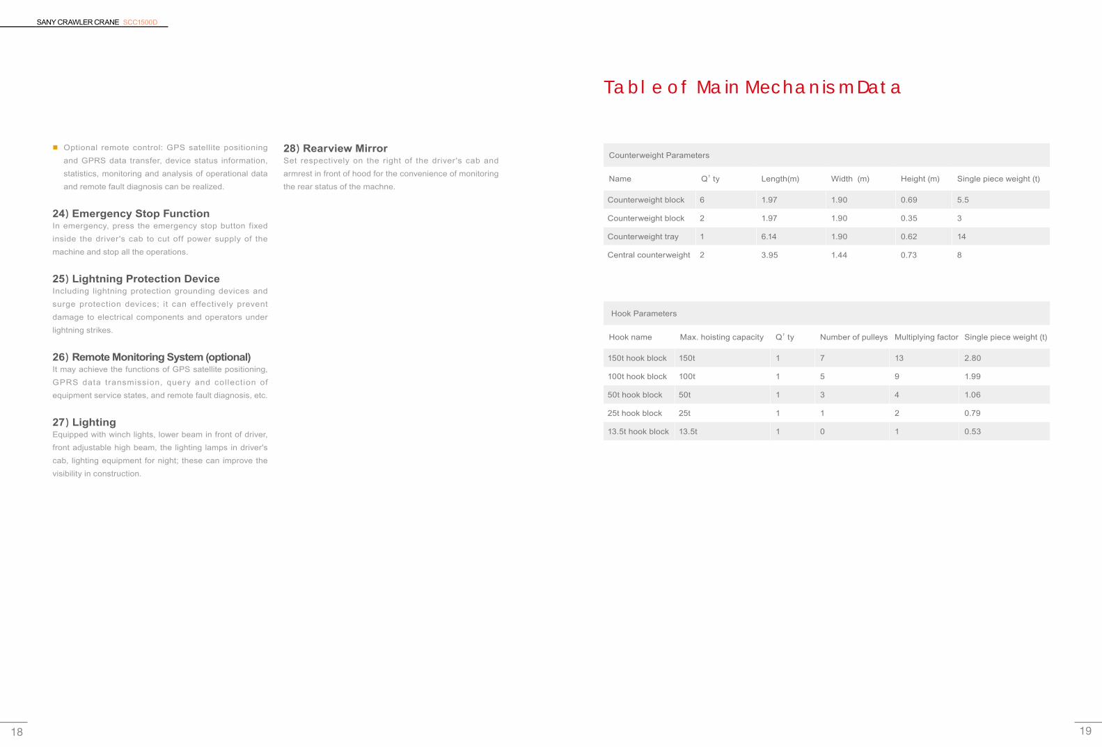
Table of Main Mechanism Data
Counterweight Parameters
Name Q’ty Length(m) Width (m) Height (m) Single piece weight (t)
Counterweight block 6 1.97 1.90 0.69 5.5
Counterweight block 2 1.97 1.90 0.35 3
Counterweight tray 1 6.14 1.90 0.62 14
Central counterweight 2 3.95 1.44 0.73 8
Hook Parameters
Hook name Max. hoisting capacity Q’ty Number of pulleys Multiplying factor Single piece weight (t)
150t hook block 150t 1 7 13 2.80
100t hook block 100t 1 5 9 1.99
50t hook block 50t 1 3 4 1.06
25t hook block 25t 1 1 2 0.79
13.5t hook block 13.5t 1 0 1 0.53
■ Optional remote control: GPS satellite positioning and GPRS data transfer, device status information, statistics, monitoring and analysis of operational data and remote fault diagnosis can be realized.
24)Emergency Stop Function In emergency, press the emergency stop button fixed inside the driver's cab to cut off power supply of the machine and stop all the operations.
25)Lightning Protection DeviceIncluding lightning protection grounding devices and surge protection devices; it can effectively prevent damage to electrical components and operators under lightning strikes.
26)Remote Monitoring System (optional) It may achieve the functions of GPS satellite positioning, GPRS data transmission, query and collection of equipment service states, and remote fault diagnosis, etc.
27)Lighting Equipped with winch lights, lower beam in front of driver, front adjustable high beam, the lighting lamps in driver's cab, lighting equipment for night; these can improve the visibility in construction.
28)Rearview MirrorSet respectively on the right of the driver's cab and armrest in front of hood for the convenience of monitoring the rear status of the machne.

SANY CRAWLER CRANE SCC1500D
21 20
SANY CRAWLER CRANE SCC1500D
20
SCC1500D
Operating Condition Combination
Operating condition of fi xed jib FJ
(69+31)/(75+13)m(53+16)t
Operating condition of light-duty boom HL
(18~81)m(53+16)t
Operating condition of light-duty boom extension HLC
(18~81)m(53+16)t
Operating Condition Combination 21HL Operating Condition of Light-duty Boom 22
Fixed Jib Opertation Condition 27

SANY CRAWLER CRANE SCC1500D
23 22
HL Operating Condition of Light-duty Boom
Boom length Insert
m 3 m 6 m 12 m
18 - - -
21 1 - -
24 - 1 -
27 1 1 -
30 - 2 -
33 1 2 -
36 - 1 1
39 1 1 1
42 - 2 1
45 1 2 1
48 - 1 2
51 1 1 2
54 - 2 2
57 1 2 2
60 - 1 3
63 1 1 3
66 - 2 3
69 1 2 3
72 - 1 4
75 1 1 4
78 - 2 4
81 1 2 4
LIGHT-DUTY AND HLC RANGE DIAGRAM
Boom tip 10.5m
12m Boom insert (4)
6m Boom insert (2)
3m Boom insert
7.5m boom base
88868482807876747270686664626058565452504846444240383634323028262422201816141210
6
1.4m
2.29
m8 10 12 14 16 18 20 22 24 26 28 30 32 34 36 38 40 42 44 46 48 50 52 54 56 58 60
78m boom
62
81m boom
75m boom
72m boom
69m boom
66m boom
63m boom
60m boom
57m boom
54m boom
51m boom
48m boom
45m boom
42m boom
39m boom
36m boom
33m boom
30m boom
27m boom
24m boom
21m boom
18m boom
Liftin
g he
ight (
m)
30°
Working Radius (m)Slewing center
40°
35°
45°
50°
55°60°65°70°75°80°

SANY CRAWLER CRANE SCC1500D
25 24
LIGHT-DUTY LOAD CHARTS
Notes:1. The rated load indicated in the table is the max.
permissible value for objects hoisted slowly and stably on a level and hard ground when the crane does not travel.
2. The rated load indicated in the table is the value computed by taking 75% of the tipover load when the wind speed is below 9.8m/s. The value of load indicated is in the unit of ton. The actual lif t ing capacity is the value obtained by deducting the weight of hoisting tools (e.g. main and auxiliary lifting hooks) from the rated lifting capacity indicated in the table.
The weight of lifting hook is shown as below:
■ 150t hook block——2.80t
■ 100t hook block——1.99t
■ 50t hook block ——1.06t
■ 25t hook block——0.79t
■ 13.5t hook block——0.53t
3. All values in the load chart are suitable for 360o swing.
SCC 1500D Crawler CraneLight-duty Load Charts 1/2
Radius(m)Boom length(m)
18 21 24 27 30 33 36 39 42 45 48
4 — — — — — — — — — — —
5 150/4.94 147.5/5.46 — — — — — — — — —
6 147.0 142.1 134.3/5.95 124.6/6.5 — — — — — — —
7 128.5 126.0 123.5 119.7 115.8 112/7.54 — — — — —
8 112.5 111.4 110.3 109.2 107.0 104.0 100/8.07 88/8.58 — — —
9 98.0 98.0 98.0 96.4 93.5 90.8 88.4 85.8 82.6/9.1 75.7/9.63 —
10 85.7 85.7 85.7 84.7 82.4 80.2 78.3 76.2 74.3 72.4 70.7/10.1
12 65.6 65.6 65.6 65.6 65.6 64.8 63.5 62.0 60.6 59.2 58.0
14 52.8 52.8 52.8 52.8 52.8 52.8 52.8 52.0 50.9 49.8 48.9
16 43.9 43.9 43.9 43.9 43.9 43.9 43.9 43.9 43.7 42.8 42.1
18 39.7/17.19 37.5 37.5 37.5 37.5 37.4 37.4 37.4 37.2 37.1 36.8
20 — 32.9/19.8 32.6 32.6 32.6 32.4 32.4 32.4 32.2 32.0 32.0
22 — — 27.9/22.4 28.6 28.6 28.5 28.5 28.4 28.3 28.1 28.1
24 — — — 25.4 25.4 25.3 25.3 25.2 25.1 24.9 24.8
26 — — — 24.2/25 22.7 22.6 22.6 22.5 22.4 22.2 22.2
28 — — — — 20.9/27.6 20.4 20.4 20.3 20.2 20.0 20.0
30 — — — — — 18.2/30.2 18.5 18.4 18.3 18.1 18.1
32 — — — — — — 16.3/32.8 16.7 16.6 16.4 16.4
34 — — — — — — — 15.3 15.2 15.0 15.0
36 — — — — — — — 14.4/35.38 13.9 13.7 13.7
38 — — — — — — — — 12.8/37.95 12.6 12.6
40 — — — — — — — — — 11.3/40.58 11.6
42 — — — — — — — — — — 10.7
44 — — — — — — — — — — 10.1/43.2
46 — — — — — — — — — — —
48 — — — — — — — — — — —
50 — — — — — — — — — — —
Counterweight (t) 53+16 53+16 53+16 53+16 53+16 53+16 53+16 53+16 53+16 53+16 53+16
Lines 13 12 11 10 10 9 8 7 7 6 6
LIGHT-DUTY LOAD CHARTS
Unit:(t)

SANY CRAWLER CRANE SCC1500D
27 26
SCC 1500D Crawler Crane Light-Duty Load Charts 2/2
Radius(m)Boom length(m)
51 54 57 60 63 66 69 72 75 78 81
10 63.6/10.6 — — — — — — — — — —
12 56.7 62.5/11.2 50.0/11.7 50.0/12.2 48.8/12.75 47.5/13.2 — — — — —
14 47.9 46.9 45.9 45.0 44.1 43.1 42.9/13.8 38.5/14.3 38.2/14.8 36.1/15.3 —
16 41.2 40.4 39.6 38.9 38.1 37.3 36.5 35.8 35.1 34.3 33.6
18 36.1 35.3 34.6 34.0 33.3 32.7 32.0 31.4 30.7 30.1 29.4
20 31.8 31.3 30.6 30.1 29.5 28.9 28.3 27.8 27.2 26.6 26.0
22 27.9 27.7 27.3 26.9 26.3 25.8 25.2 24.8 24.2 23.7 23.1
24 24.7 24.5 24.3 24.2 23.6 23.1 22.6 22.2 21.7 21.2 20.7
26 22.0 21.8 21.6 21.5 21.3 20.9 20.4 20.0 19.5 19.1 18.6
28 19.8 19.6 19.4 19.3 19.1 18.9 18.5 18.1 17.7 17.2 16.8
30 17.9 17.7 17.5 17.4 17.2 17.0 16.8 16.5 16.0 15.6 15.2
32 16.2 16.0 15.8 15.7 15.5 15.3 15.1 15.0 14.6 14.2 13.8
34 14.8 14.6 14.4 14.3 14.1 13.9 13.7 13.6 13.3 12.9 12.5
36 13.5 13.3 13.1 13.0 12.8 12.6 12.4 12.3 12.1 11.8 11.4
38 12.4 12.2 12.0 11.9 11.7 11.5 11.3 11.2 10.9 10.7 10.4
40 11.4 11.2 11.0 10.9 10.7 10.5 10.3 10.2 9.9 9.7 9.5
42 10.5 10.3 10.1 10.0 9.8 9.6 9.4 9.3 9.0 8.8 8.6
44 9.6 9.5 9.3 9.2 9.0 8.8 8.5 8.4 8.2 8.0 7.8
46 9/45.75 8.7 8.5 8.4 8.2 8.0 7.8 7.7 7.5 7.3 7.0
48 — 7.9/48.38 7.8 7.8 7.6 7.4 7.1 7.0 6.8 6.6 6.3
50 — — 7.2 7.1 6.9 6.7 6.5 6.4 6.2 6.0 5.7
52 — — 6.9/50.97 6.6 6.4 6.2 5.9 5.8 5.6 5.4 5.2
54 — — — 6.1/53.57 5.8 5.6 5.4 5.3 5.1 4.9 4.6
56 — — — — 5.3/56.16 5.1 4.9 4.8 4.6 4.4 4.1
58 — — — — — 4.5/58.8 4.5 4.4 4.1 3.9 3.7
60 — — — — — — 4.0 3.9 3.7 3.5 3.3
62 — — — — — — 3.7/61.4 3.5 3.3 3.1 2.9
64 — — — — — — — 3.1 2.9 2.7 2.5
66 — — — — — — — — 2.6 2.4 2.1
68 — — — — — — — — 2.4/66.5 2.0 1.8
70 — — — — — — — — — 1.9/69.2 1.5
Counterweight (t) 53+16 53+16 53+16 53+16 53+16 53+16 53+16 53+16 53+16 53+16 53+16
Lines 5 5 4 4 4 4 4 3 3 3 3
Unit:(t)
LIGHT-DUTY LOAD CHARTS FIXED JIB OPERTATION CONDITION
Jib length (m)Insert
Boom length (m)
Angle between boom
and jib3 m 6 m
13 1 - 27~75 15°,30°
19 1 1 27~69 15°,30°
25 1 2 33~69 15°,30°
31 1 3 39~69 15°,30°
Boom 27~75m
Jib 13~31m
30°(15°)
Jib base 5m
6m insert
3m insert
Jib tip 5m
SANY CRAWLER CRANE SCC1500D
29 28
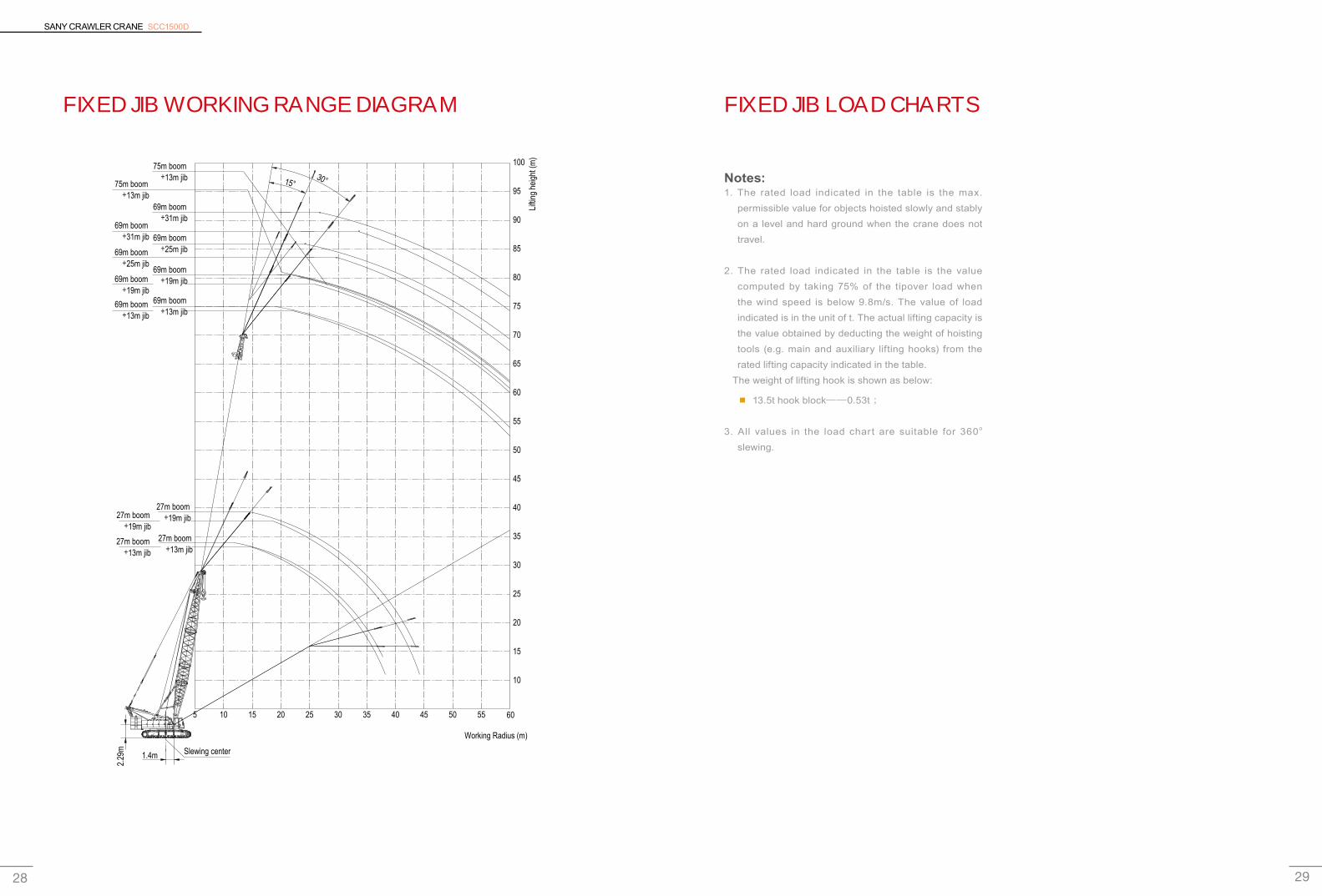
FIXED JIB WORKING RANGE DIAGRAM FIXED JIB LOAD CHARTS
Notes:1. The rated load indicated in the table is the max.
permissible value for objects hoisted slowly and stably on a level and hard ground when the crane does not travel.
2. The rated load indicated in the table is the value computed by taking 75% of the tipover load when the wind speed is below 9.8m/s. The value of load indicated is in the unit of t. The actual lifting capacity is the value obtained by deducting the weight of hoisting tools (e.g. main and auxiliary lifting hooks) from the rated lifting capacity indicated in the table.
The weight of lifting hook is shown as below:
■ 13.5t hook block——0.53t ;
3. All values in the load chart are suitable for 360o
slewing.
100
95
90
85
80
75
70
65
60
55
50
45
40
35
30
25
20
15
10
1.4m
2.29
m
10 20 30 40155 5025 35 5545 60
75m boom +13m jib
75m boom +13m jib
69m boom +31m jib
69m boom +31m jib 69m boom
+25m jib
69m boom +19m jib
69m boom +13m jib
27m boom +19m jib27m boom
+19m jib27m boom +13m jib
27m boom +13m jib
69m boom +13m jib
69m boom +19m jib
69m boom +25m jib
Liftin
g he
ight (
m)
Working Radius (m)
Slewing center
30°15°

SANY CRAWLER CRANE SCC1500D
31 30
FIXED JIB LOAD CHARTS
SCC 1500D Crawler CraneFixed Jib Load Charts 1/5
Boom length (m) 27 30 33
Jib length (m) 13 19 13 19 13 19
Jib angle Radius (m)
15° 30° 15° 30° 15° 30° 15° 30° 15° 30° 15° 30°
12 13.0/12.3 13.0/12.9 13.0/13.4
14 13.0 9.0/15.1 8.0/14.9 13.0 9.0/15.7 8.0/15.5 13.0
16 13.0 9.0 8.0 13.0 9.0 8.0 13.0 9.0/16.3 8.0/16.1
18 13.0 9.0 8.0 6.0/19.1 13.0 9.0 8.0 6.0/19.6 13.0 9.0 8.0
20 13.0 9.0 8.0 6.0 13.0 9.0 8.0 6.0 13.0 9.0 8.0 6.0/20.2
22 13.0/23.2 9.0 8.0 6.0 13.0 9.0 8.0 6.0 13.0 9.0 8.0 6.0
24 12.7 9.0 8.0 6.0 13.0/24.8 9.0 8.0 6.0 13.0 9.0 8.0 6.0
26 12.3/24.9 9.0/24.9 8.0/24.9 6.0/24.9 12.5 9.0 8.0 6.0 13.0 9.0 8.0 6.0
28 11.9/27.5 9.0/27.5 8.0/27.5 6.0/27.5 12.3 9.0 8.0 6.0
30 11.6/30.1 9.0/30.1 8.0/30.1 6.0/30.1
32
34
Counterweight (t) 53+16
Boom length (m) 33 36 39
Jib length (m) 25 13 19 25 13 19
Jib angle Radius (m)
15° 30° 15° 30° 15° 30° 15° 30° 15° 30° 15° 30°
14 13.0/14.1 13.0/14.6
16 13.0 9.0/16.9 8.0/16.7 13.0 9.0/17.4 8.0/17.2
18 5.0/18.7 13.0 9.0 8.0 5.0/19.3 13.0 9.0 8.0
20 5.0 13.0 9.0 8.0 6.0/20.8 5.0 13.0 9.0 8.0 6.0/21.4
22 5.0 13.0 9.0 8.0 6.0 5.0 13.0 9.0 8.0 6.0
24 5.0 4.6/24.2 13.0 9.0 8.0 6.0 5.0 4.6/24.7 13.0 9.0 8.0 6.0
26 5.0 4.6 13.0/27.6 9.0 8.0 6.0 5.0 4.6 13.0 9.0 8.0 6.0
28 5.0 4.6 12.8 9.0 8.0 6.0 5.0 4.6 13.0/29.0 9.0 8.0 6.0
30 5.0/30.1 4.6/30.1 12.2 9.0 8.0 6.0 5.0 4.6 12.7 9.0 8.0 6.0
32 11.6 9.0 8.0 6.0 5.0 4.6 12.1 9.0 8.0 6.0
34 11.4/32.7 9.0/32.7 8.0/32.7 6.0/32.7 5.0/32.7 4.6/32.7 11.5 9.0 8.0 6.0
36 10.9/35.3 9.0/35.3 8.0/35.3 6.0/35.3
Counterweight (t) 53+16
Unit:(t)
FIXED JIB LOAD CHARTS
SCC 1500D Crawler CraneFixed Jib Load Charts 2/5
Boom length (m) 39
Jib length (m) 25 31Jib angle
Radius (m)15° 30° 15° 30°
14
16
18 5.0/19.9
20 5.0
22 5.0 3.0/22.5
24 5.0 4.6/25.3 3.0
26 5.0 4.6 3.0
28 5.0 4.6 3.0 2.6/29.2
30 5.0 4.6 3.0 2.6
32 5.0 4.6 3.0 2.6
34 5.0 4.6 3.0 2.6
36 5.0/35.3 4.6/35.3 3.0/35.3 2.6/35.3
Counterweight (t) 53+16
Boom length (m) 42 45
Jib length (m) 13 19 25 31 13 19Jib angle
Radius (m) 15° 30° 15° 30° 15° 30° 15° 30° 15° 30° 15° 30°
16 13.0/15.2 8.0/17.8 13.0/15.7
18 13.0 8.0 13.0 9.0/18.6 8.0/18.4
20 13.0 9.0 8.0 6.0/21.9 5.0/20.4 13.0 9.0 8.0
22 13.0 9.0 8.0 6.0 5.0 3.0/23.1 13.0 9.0 8.0 6.0/22.5
24 13.0 9.0 8.0 6.0 5.0 4.6/25.9 3.0 13.0 9.0 8.0 6.0
26 13.0 9.0 8.0 6.0 5.0 4.6 3.0 13.0 9.0 8.0 6.0
28 13.0 9.0 8.0 6.0 5.0 4.6 3.0 2.6/29.8 13.0 9.0 8.0 6.0
30 13.0 9.0 8.0 6.0 5.0 4.6 3.0 2.6 13.0 9.0 8.0 6.0
32 13.0 9.0 8.0 6.0 5.0 4.6 3.0 2.6 13.0 9.0 8.0 6.0
34 13.0 9.0 8.0 6.0 5.0 4.6 3.0 2.6 12.0 9.0 8.0 6.0
36 12.1 9.0 8.0 6.0 5.0 4.6 3.0 2.6 11.0 9.0 8.0 6.0
38 11.1 9.0 8.0/37.9 6.0/37.9 5.0/37.9 4.6/37.9 3.0/37.9 2.5/37.9 10.2 9.0 8.0 6.0
40 9.6/37.9 9.0/37.9 9.4 9.0 8.0 6.0
42 9.2/40.5 9.0/40.5 8.0/40.5 6.0/40.5
Counterweight (t) 53+16
Unit:(t)
SANY CRAWLER CRANE SCC1500D
33 32
FIXED JIB LOAD CHARTS
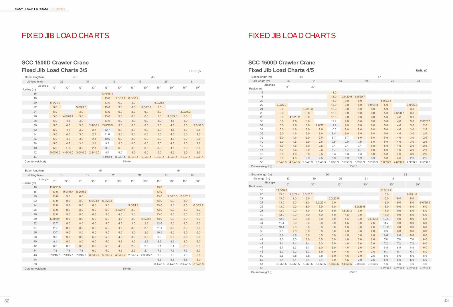
SCC 1500D Crawler CraneFixed Jib Load Charts 3/5
Boom length (m) 45 48
Jib length (m) 25 31 13 19 25 31Jib angle
Radius (m) 15° 30° 15° 30° 15° 30° 15° 30° 15° 30° 15° 30°
16 13.0/16.3
18 13.0 9.0/19.1 8.0/18.920 5.0/21.0 13.0 9.0 8.0 5.0/21.622 5.0 3.0/23.6 13.0 9.0 8.0 6.0/23.1 5.0 24 5.0 3.0 13.0 9.0 8.0 6.0 5.0 3.0/24.226 5.0 4.6/26.4 3.0 13.0 9.0 8.0 6.0 5.0 4.6/27.0 3.0 28 5.0 4.6 3.0 13.0 9.0 8.0 6.0 5.0 4.6 3.0
30 5.0 4.6 3.0 2.4/30.4 13.0/30.5 9.0 8.0 6.0 5.0 4.6 3.0 2.6/31.0
32 5.0 4.6 3.0 2.4 12.7 9.0 8.0 6.0 5.0 4.6 3.0 2.6
34 5.0 4.6 3.0 2.4 11.6 9.0 8.0 6.0 5.0 4.6 3.0 2.6
36 5.0 4.6 3.0 2.4 10.6 9.0 8.0 6.0 5.0 4.6 3.0 2.6
38 5.0 4.6 3.0 2.4 9.8 9.0 8.0 6.0 5.0 4.6 3.0 2.6
40 5.0 4..6 3.0 2.4 9.0 9.0 8.0 6.0 5.0 4.6 3.0 2.6
42 5.0/40.5 4.6/40.5 3.0/40.5 2.4/40.5 8.4 8.6 8.0 6.0 5.0 4.6 3.0 2.6
44 8.1/43.1 8.2/43.1 8.0/43.1 6.0/43.1 5.0/43.1 4.6/43.1 3.0/43.1 2.6/43.1
Counterweight (t) 53+16
Boom length (m) 51 54Jib length (m) 13 19 25 31 13 19
Jib angle Radius (m)
15° 30° 15° 30° 15° 30° 15° 30° 15° 30° 15° 30°
16 13.0/16.9 13.0 18 13.0 9.0/19.7 8.0/19.5 13.0 20 13.0 9.0 8.0 13.0 9.0/20.3 8.0/20.122 13.0 9.0 8.0 6.0/23.6 5.0/22.1 13.0 9.0 8.0 24 13.0 9.0 8.0 6.0 5.0 3.0/24.8 13.0 9.0 8.0 6.0/24.226 13.0 9.0 8.0 6.0 5.0 4.6/27.6 3.0 13.0 9.0 8.0 6.0 28 13.0 9.0 8.0 6.0 5.0 4.6 3.0 13.0 9.0 8.0 6.0 30 13.0/30.1 9.0 8.0 6.0 5.0 4.6 3.0 2.6/31.5 13.0 9.0 8.0 6.0 32 12.7 9.0 8.0 6.0 5.0 4.6 3.0 2.6 12.6 9.0 8.0 6.0 34 11.7 9.0 8.0 6.0 5.0 4.6 3.0 2.6 11.4 9.0 8.0 6.0 36 10.7 9.0 8.0 6.0 5.0 4.6 3.0 2.6 10.5 9.0 8.0 6.0 38 9.8 9.0 8.0 6.0 5.0 4.6 3.0 2.6 9.6 9.0 8.0 6.0 40 9.1 9.0 8.0 6.0 5.0 4.6 3.0 2.5 8.9 8.9 8.0 6.0 42 8.3 8.3 8.0 6.0 5.0 4.6 2.9 2.5 8.1 8.1 8.0 6.0 44 7.8 7.8 7.8 6.0 5.0 4.6 2.9 2.4 7.6 7.6 7.6 6.0 46 7.3/45.7 7.3/45.7 7.3/45.7 6.0/45.7 5.0/45.7 4.6/45.7 2.8/45.7 2.35/45.7 7.0 7.0 7.0 6.0 48 6.5 6.5 6.5 6.0 50 6.4/48.3 6.4/48.3 6.4/48.3 6.0/48.3
Counterweight (t) 53+16
Unit:(t)
FIXED JIB LOAD CHARTS
SCC 1500D Crawler CraneFixed Jib Load Charts 4/5
Boom length (m) 54 57Jib length (m) 25 31 13 19 25 31
Jib angle Radius (m)
15° 30°
16 13.0 18 13.0 9.0/20.9 8.0/20.720 13.0 9.0 8.0 5.0/23.322 5.0/22.7 13.0 9.0 8.0 6.0/24.8 5.0 3.0/25.524 5.0 3.0/25.3 13.0 9.0 8.0 6.0 5.0 3.0 26 5.0 3.0 13.0 9.0 8.0 6.0 5.0 4.6/28.7 3.0 28 5.0 4.6/28.2 3.0 13.0 9.0 8.0 6.0 5.0 4.6 3.0 30 5.0 4.6 3.0 12.4 9.0 8.0 6.0 5.0 4.6 3.0 2.6/32.732 5.0 4.6 3.0 2.6/32.1 11.2 9.0 8.0 6.0 5.0 4.6 3.0 2.6 34 5.0 4.6 3.0 2.6 10.3 9.0 8.0 6.0 5.0 4.6 3.0 2.6 36 5.0 4.6 3.0 2.6 9.4 9.0 8.0 6.0 5.0 4.6 3.0 2.6 38 5.0 4.6 3.0 2.6 8.7 8.7 8.0 6.0 5.0 4.6 3.0 2.6 40 5.0 4.6 3.0 2.6 7.9 7.9 7.9 6.0 5.0 4.6 3.0 2.6 42 5.0 4.6 3.0 2.6 7.4 7.4 7.4 6.0 5.0 4.6 3.0 2.6 44 5.0 4.6 3.0 2.6 6.7 6.7 6.7 6.0 5.0 4.6 3.0 2.6 46 5.0 4.6 3.0 2.6 6.3 6.3 6.3 6.0 5.0 4.6 3.0 2.6 48 5.0 4.6 2.9 2.5 5.9 5.9 5.9 5.9 5.0 4.6 2.9 2.5 50 5.0/48.3 4.6/48.3 2.9/48.3 2.5/48.3 5.7/50.9 5.7/50.9 5.7/50.9 5.7/50.9 5.0/50.9 4.6/50.9 2.9/50.9 2.5/50.9
Counterweight (t) 53+16
Boom length (m) 60 63Jib length (m) 13 19 25 31 13 19
Jib angle Radius (m)
15° 30° 15° 30° 15° 30°
18 13.0/18.6 13.0/19.220 13.0 9.0/21.4 8.0/21.2 13.0 8.0/21.822 13.0 9.0 8.0 5.0/23.9 13.0 9.0 8.0 24 13.0 9.0 8.0 6.0/25.4 5.0 13.0 9.0 8.0 6.0/25.926 13.0 9.0 8.0 6.0 5.0 3.0/26.5 13.0 9.0 8.0 6.0 28 13.0 9.0 8.0 6.0 5.0 4.6/29.3 3.0 13.0 9.0 8.0 6.0 30 13.0 9.0 8.0 6.0 5.0 4.6 3.0 13.0 9.0 8.0 6.0 32 12.6 9.0 8.0 6.0 5.0 4.6 3.0 2.6/33.2 12.4 9.0 8.0 6.0 34 11.4 9.0 8.0 6.0 5.0 4.6 3.0 2.6 11.2 9.0 8.0 6.0 36 10.4 9.0 8.0 6.0 5.0 4.6 3.0 2.6 10.2 9.0 8.0 6.0 38 9.5 9.0 8.0 6.0 5.0 4.6 3.0 2.6 9.3 9.0 8.0 6.0 40 8.8 8.8 8.0 6.0 5.0 4.6 3.0 2.6 8.6 8.6 8.0 6.0 42 8.0 8.0 8.0 6.0 5.0 4.6 3.0 2.6 7.8 7.8 7.8 6.0 44 7.4 7.4 7.4 6.0 5.0 4.6 3.0 2.6 7.2 7.2 7.2 6.0 46 6.7 6.7 6.7 6.0 5.0 4.6 3.0 2.6 6.5 6.5 6.5 6.0 48 6.3 6.3 6.3 6.0 5.0 4.6 3.0 2.6 6.1 6.1 6.1 6.0 50 5.8 5.8 5.8 5.8 5.0 4.6 3.0 2.5 5.6 5.6 5.6 5.6 52 5.4 5.4 5.4 5.4 5.0 4.6 2.9 2.5 5.0 5.0 5.0 5.0 54 5.0/53.5 5.0/53.5 5.0/53.5 5.0/53.5 5.0/53.5 4.6/53.5 2.9/53.5 2.4/53.5 4.6 4.6 4.6 4.6 56 4.2/56.1 4.2/56.1 4.2/56.1 4.2/56.1
Counterweight (t) 53+16
Unit:(t)

SANY CRAWLER CRANE SCC1500D
35 34
FIXED JIB LOAD CHARTS
SCC 1500D Crawler CraneFixed Jib Load Charts 5/5
Boom length (m) 63 66Jib length (m) 25 31 13 19 25 31
Jib angle Radius (m)
15° 30° 15° 30° 15° 30°
18 13.0/19.220 13.0 22 13.0 9.0/22.6 8.0/22.424 5.0/24.4 13.0 9.0 8.0 5.0/25.026 5.0 3.0/27.1 13.0 9.0 8.0 6.0/26.5 5.0 3.0/27.628 5.0 4.6/29.9 3.0 13.0 9.0 8.0 6.0 5.0 3.0 30 5.0 4.6 3.0 13.0 9.0 8.0 6.0 5.0 4.6/30.4 3.0 32 5.0 4.6 3.0 2.6/33.8 12.2 9.0 8.0 6.0 5.0 4.6 3.0 34 5.0 4.6 3.0 2.6 11.1 9.0 8.0 6.0 5.0 4.6 3.0 2.6/34.436 5.0 4.6 3.0 2.6 10.1 9.0 8.0 6.0 5.0 4.6 3.0 2.6 38 5.0 4.6 3.0 2.6 9.2 9.0 8.0 6.0 5.0 4.6 3.0 2.6 40 5.0 4.6 3.0 2.6 8.3 8.3 8.0 6.0 5.0 4.6 3.0 2.6 42 5.0 4.6 3.0 2.6 7.6 7.6 7.6 6.0 5.0 4.6 3.0 2.6 44 5.0 4.6 3.0 2.6 7.0 7.0 7.0 6.0 5.0 4.6 3.0 2.6 46 5.0 4.6 3.0 2.6 6.4 6.4 6.4 6.0 5.0 4.6 3.0 2.6 48 5.0 4.6 3.0 2.6 5.9 5.9 5.9 5.9 5.0 4.6 3.0 2.6 50 5.0 4.6 3.0 2.5 5.4 5.4 5.4 5.4 5.0 4.6 3.0 2.5 52 5.0 4.6 3.0 2.5 4.8 4.8 4.8 4.8 4.8 4.6 3.0 2.5 54 4.6 4.6 2.9 2.4 4.4 4.4 4.4 4.4 4.4 4.4 2.9 2.4 56 4.2/56.1 4.2/56.1 2.9/56.1 2.3/56.1 4.0 4.0 4.0 4.0 4.0 4.0 2.9 2.4 58 3.5 3.5 3.5 3.5 3.5 3.5 2.8 2.3 60 3.4/58.7 3.4/58.7 3.4/58.7 3.4/58.7 3.4/58.7 3.4/58.7 2.8/58.7 2.2/58.7
Counterweight (t) 53+16
Boom length (m) 69 75Jib length (m) 13 19 25 31 13
Jib angle Radius (m)
15° 30° 15° 30° 15°
18 20 13.0/20.3 13.0/21.522 13.0 9.0/23.1 8.0/22.9 13.0 24 13.0 9.0 8.0 5.0/25.6 13.0 9.0/24.326 13.0 9.0 8.0 6.0/27.1 5.0 13.0 9.0 28 13.0 9.0 8.0 6.0 5.0 3.0/28.2 13.0 9.0 30 13.0 9.0 8.0 6.0 5.0 4.6/31.0 3.0 13.0 9.0 32 12.2 9.0 8.0 6.0 5.0 4.6 3.0 11.8 9.0 34 11.0 9.0 8.0 6.0 5.0 4.6 3.0 2.6/35.0 10.6 9.0 36 10.0 9.0 8.0 6.0 5.0 4.6 3.0 2.6 9.5 9.0 38 9.1 9.0 8.0 6.0 5.0 4.6 3.0 2.6 8.7 8.7 40 8.2 8.2 8.0 6.0 5.0 4.6 3.0 2.6 7.8 7.8 42 7.6 7.6 7.6 6.0 5.0 4.6 3.0 2.6 7.1 7.1 44 7.0 7.0 7.0 6.0 5.0 4.6 3.0 2.6 6.4 6.4 46 6.3 6.3 6.3 6.0 5.0 4.6 3.0 2.6 5.8 5.8 48 5.8 5.8 5.8 5.8 5.0 4.6 3.0 2.6 5.1 5.1 50 5.2 5.2 5.2 5.2 5.0 4.6 3.0 2.5 4.6 4.6 52 4.7 4.7 4.7 4.7 4.7 4.6 3.0 2.5 4.1 4.1 54 4.2 4.2 4.2 4.2 4.2 4.2 2.9 2.4 3.6 3.6 56 3.7 3.7 3.7 3.7 3.7 3.7 2.9 2.4 3.2 3.2 58 3.4 3.4 3.4 3.4 3.4 3.4 2.8 2.3 2.8 2.8 60 3.0 3.0 3.0 3.0 3.0 3.0 2.8 2.2 2.4 2.4
Counterweight (t) 53+16
Unit:(t)
Notes

SANY CRAWLER CRANE SCC1500D
37 36
NotesNotes

Quality Changes the World
Address: SANY Industrial Park, No. 8 Beiqing Road, Huilongguan Town, Changping District, BeijingService Hotline: +0086-4006-098-318Email: [email protected] mord information, pleas visit:www.sanygroup.comB0502ENAN1-SCC1500DFor our consistent improvement in techonology,specifcations may change without noticeThe machines illustrated may show optional equipment which can be supplied at additional cost.
Version:2015.10
Top Related