


Languages
Pages
Legal

SACO 64D4Annunciator unit
User´s manual and Technical description
FAULT
ON
PROGRAM
1 2 3 4
5 6 7 8
9 10 11 12
13 14 15 16TEST
RESET
ACK
SILENCE
FAULT
ON
PROGRAM
1 2 3 4
5 6 7 8
9 10 11 12
13 14 15 16
FAULT
ON
PROGRAM
1 2 3 4
5 6 7 8
9 10 11 12
13 14 15 16
FAULT
ON
PROGRAM
1 2 3 4
5 6 7 8
9 10 11 12
13 14 15 16
SACO 16D2 SACO 16D2 SACO 16D2 SACO 16D2
2
1MRS 752014-MUM EN
Issued 2000-11-22Modified 2003-10-14Version B (replaces 34 SACO 64 1 EN1)Checked PSApproved MÖ
Data subject to change without notice
SACO 64D4Annunciator unit
Table of contents Features .......................................................................................................................... 3General ........................................................................................................................... 3Areas of appIication ........................................................................................................ 3Ilustration of function .................................................................................................... 4
General system data ................................................................................................... 4Example of system arrangement ................................................................................ 6Mechanical design ..................................................................................................... 8
Function of the annunciator module .................................................................... 9Field contact circuits .......................................................................................... 10Alarm channel functions .................................................................................... 10Visual alarm indication....................................................................................... 12Standardized operational sequences .................................................................... 12Event register for the serial communication ........................................................ 14Auxiliary outputs ................................................................................................ 15Group alarm reflash signals ................................................................................. 15Field contact follower output.............................................................................. 16Lamp follower output ......................................................................................... 17Audible device output ........................................................................................ 17Interlockings ...................................................................................................... 18Example of channel interlocking configuration .................................................. 19
Serial communication interface ............................................................................... 20Synchronizing of the blinking sequence ............................................................. 20
Parameterization ...................................................................................................... 21Auxiliary power supply system (modified 03-10) ...................................................... 21Self-supervision output ............................................................................................ 22Application .............................................................................................................. 23
Mounting ........................................................................................................... 23Connection diagram ........................................................................................... 24Terminals and wiring .......................................................................................... 25Mounting and connection of acknowledge module SWDM 3A1 ....................... 26Connection to a distributed system with or without event sequence reporting ... 27Connection to a distributed system .................................................................... 27Connection of a relay output extension unit type SACO 128R4 ........................ 28Start-up .............................................................................................................. 28Operational test .................................................................................................. 28Legend plate ....................................................................................................... 29
Programming ................................................................................................................ 30Signalling and reporting functions ........................................................................... 30Parameter selection key ............................................................................................ 32Parameter chart ........................................................................................................ 32Channel interlocking scheme................................................................................... 33Remote information to and from the alarm annunciator ......................................... 34Event codes .............................................................................................................. 38
Technical data (modified 03-10) .................................................................................... 38Testing .......................................................................................................................... 40Maintenance and repair ................................................................................................ 40Spareparts ..................................................................................................................... 41Order information ........................................................................................................ 42Troubleshooting ............................................................................................................ 42
3
Complete annunciator unit with 64 channelsfor operation from NO or NC field contacts
Fibre-optic or electric data bus between thealarm units
Resolution better than 10 ms in the event re-cording
Independently operating alarm modules
Features Each module provided with a sophisticatedself-supervision system
16 relay reflashes to be freely grouped
Easy programming via SMS Software or a sepa-rate programming module SACO 16PM
Sophisticated built-in self-supervision system forencreased reliability
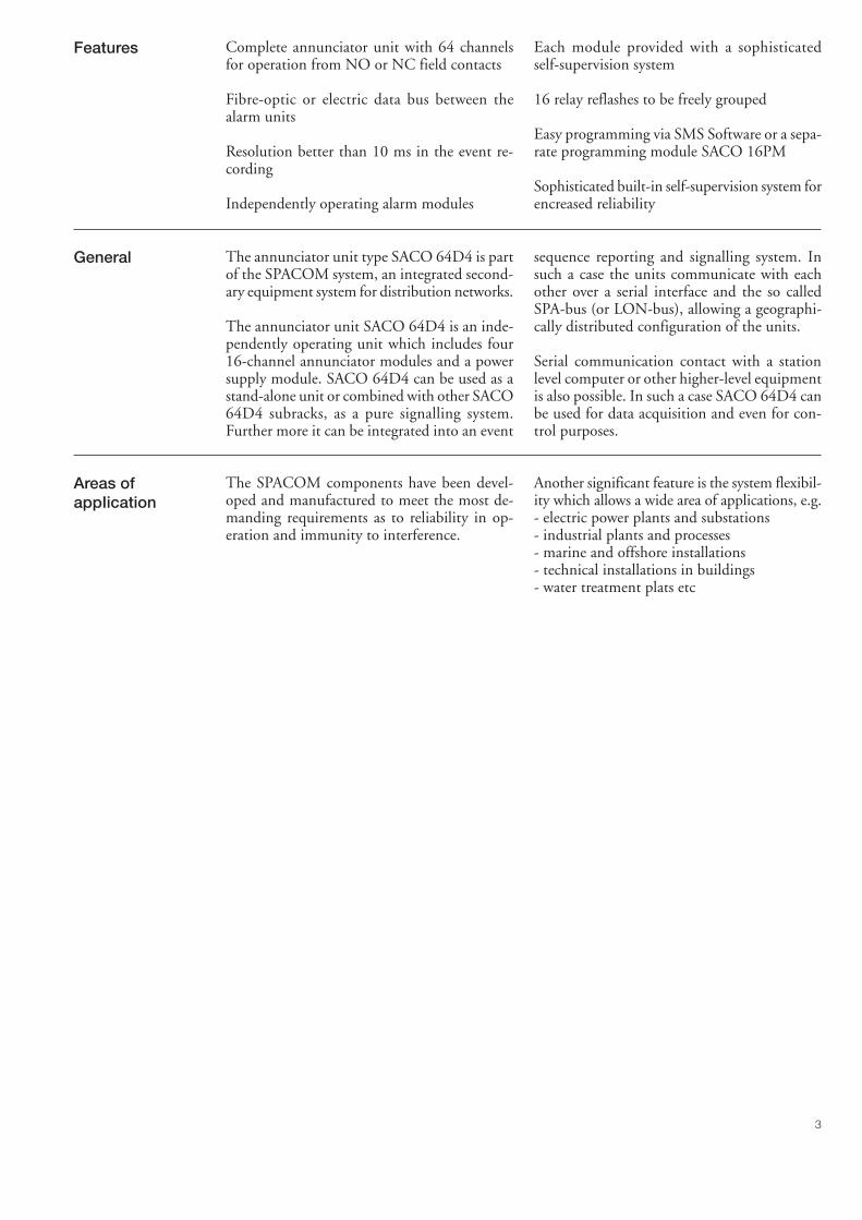
General The annunciator unit type SACO 64D4 is partof the SPACOM system, an integrated second-ary equipment system for distribution networks.
The annunciator unit SACO 64D4 is an inde-pendently operating unit which includes four16-channel annunciator modules and a powersupply module. SACO 64D4 can be used as astand-alone unit or combined with other SACO64D4 subracks, as a pure signalling system.Further more it can be integrated into an event
sequence reporting and signalling system. Insuch a case the units communicate with eachother over a serial interface and the so calledSPA-bus (or LON-bus), allowing a geographi-cally distributed configuration of the units.
Serial communication contact with a stationlevel computer or other higher-level equipmentis also possible. In such a case SACO 64D4 canbe used for data acquisition and even for con-trol purposes.
Areas ofappIication
The SPACOM components have been devel-oped and manufactured to meet the most de-manding requirements as to reliability in op-eration and immunity to interference.
Another significant feature is the system flexibil-ity which allows a wide area of applications, e.g.- electric power plants and substations- industrial plants and processes- marine and offshore installations- technical installations in buildings- water treatment plats etc
4
Ilustration offunction
General system data
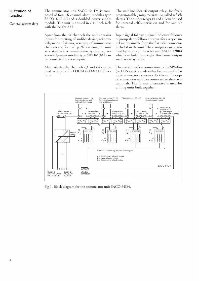
The annunciator unit SACO 64 D4 is com-posed of four 16-channel alarm modules typeSACO 16 D2B and a doubled power supplymodule. The unit is housed in a 19 inch rackwith the height 3 U.
Apart from the 64 channels the unit containsinputs for resetting of audible device, acknow-ledgement of alarms, resetting of annunciatorchannels and for testing. When using the unitas a stand-alone annunciator system, an ac-knowledgement module type SWDM 3A1 canbe connected to these inputs.
Alternatively, the channels 63 and 64 can beused as inputs for LOCAL/REMOTE func-tions.
The unit includes 16 output relays for freelyprogrammable group realarms, so called reflashalarms. The output relays 15 and 16 can be usedfor internal self-supervision and for audiblealarm.
Input signal follower, signal indicator followeror group alarm follower outputs for every chan-nel are obtainable from the flat cable connectorincluded in the unit. These outputs can be uti-lized by means of the relay unit SACO 128R4which can hold up to eight 16-channel outputauxiliary relay cards.
The serial interface connection to the SPA-bus(or LON-bus) is made either by means of a flatcable connector between subracks or fiber op-tic connection modules connected to the screwterminals. The former alternative is used foruniting units built together.
16
A
16B
SACO 16D2
C16
A
16B
SACO 16D2
C16
A
16B
SACO 16D2
C16
A
16B
SACO 16D2
C
16
SACO 64D4
Field contactsupply, 48 V DC
Channel inputs 1…16Remote silence andacknowledge inputs
Channel inputs 17…32Remote channel resetand test inputs
Channel inputs 33…48 Channel inputs 49…64(Local/remote inputs)
Group alarmoutputs, 1…4
Group alarmoutputs, 5…8
Group alarmoutputs, 9…12
Group alarmoutputs, 1…4Audible outputSelf-supervision output
Internalsupply
SPA-bus, supervising bus and blocking bus
A = Field contact follower outputB = Lamp follower outputC = Group alarm reflash output
SPA-busconnection
Supply 2:80…265 VAC or DC
Supply 1:19…70 V DC or80…256 V DC
Fig 1. Block diagram for the annunciator unit SACO 64D4.
5
The same flat cable further contains a monitor-ing bus for internal faults and an interlockingbus for the transmission of interlocking signalsbetween the annunciator modules. When seve-ral annunciator units SACO 64D4 are builttogether, the SPA-bus can be used for synchro-nizing the flashing sequence of the alarm indi-cators of the modules.
In a distributed system bus connection mod-ules type SPA-ZC_ are used for connecting theannunciator unit to the SPA-bus. Bus connec-tion modules are available for both optical andelectrical data transmission. The transmissiondistances vary with the transmission media, thefollowing values can be given:- plastic-fibre: at least 30 m- glass-fibre: at least 1 km- pairs of twisted conductor without galvanic
isolation: at least 30 m- pairs of twisted conductor with galvanic iso-
lation: at least 200 m
Fiber optic media is always recommended dueto its good resistance to electromagnetical in-terference.
The setting values, groupings and interlockingsof the annunciator modules are stored in non-volatile memories.
In a stand-alone annunciator system without ahigher level system connected the modules canbe programmed by temporarily connecting theprogramming module SACO 16PM to the an-nunciator modules SACO 16D2B.
If SACO 64D4 is connected to a higher levelsystem, e.g MicroSCADA the programmingmight be made from there. A SMS software canalso be used for programming the SACO 64D4.
6
Example of systemarrangement
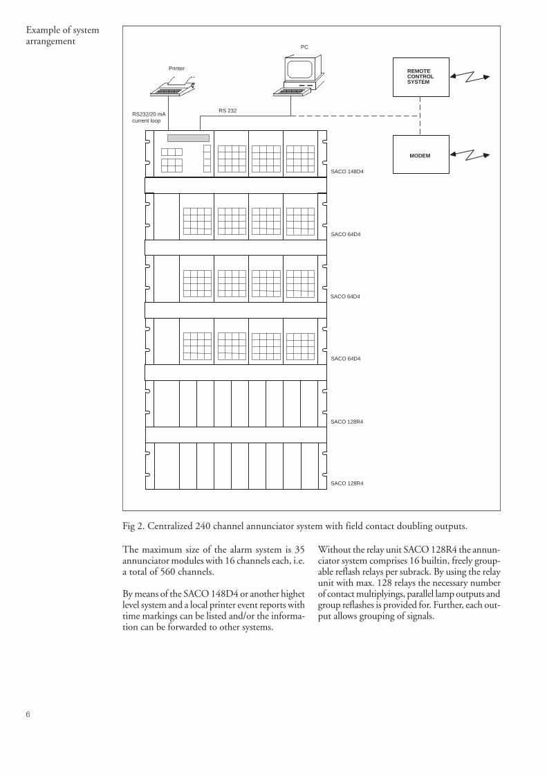
Fig 2. Centralized 240 channel annunciator system with field contact doubling outputs.
The maximum size of the alarm system is 35annunciator modules with 16 channels each, i.e.a total of 560 channels.
By means of the SACO 148D4 or another highetlevel system and a local printer event reports withtime markings can be listed and/or the informa-tion can be forwarded to other systems.
Without the relay unit SACO 128R4 the annun-ciator system comprises 16 builtin, freely group-able reflash relays per subrack. By using the relayunit with max. 128 relays the necessary numberof contact multiplyings, parallel lamp outputs andgroup reflashes is provided for. Further, each out-put allows grouping of signals.
RS 232
SACO 148D4
SACO 64D4
SACO 64D4
SACO 128R4
SACO 128R4
SACO 64D4
RS232/20 mAcurrent loop
Printer
PC
MODEM
REMOTECONTROLSYSTEM
7
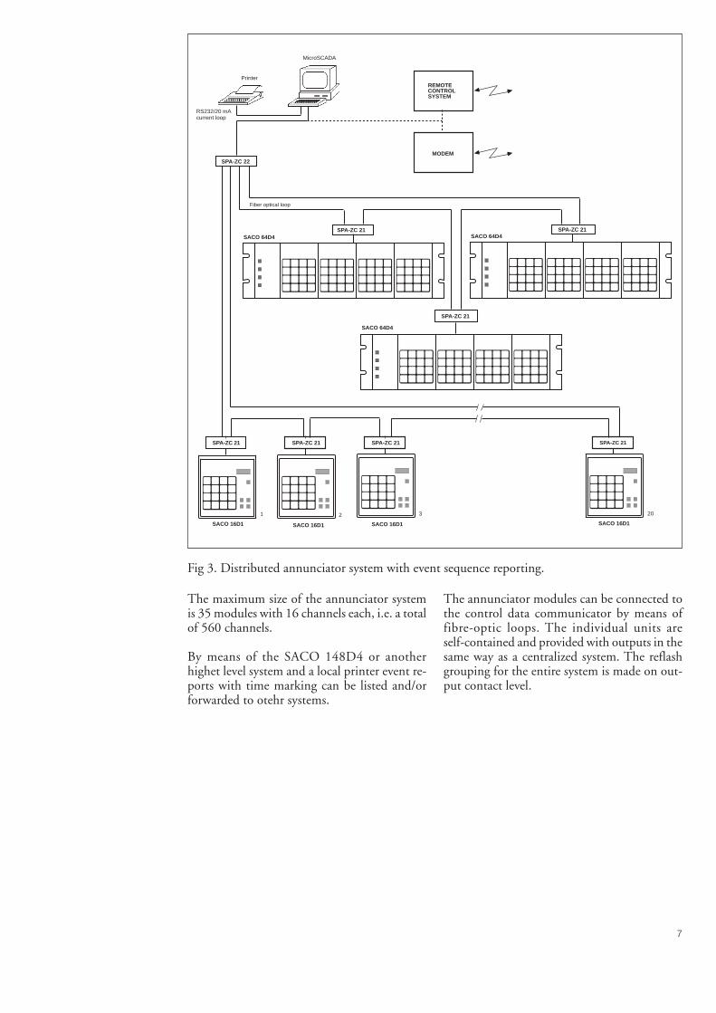
Fig 3. Distributed annunciator system with event sequence reporting.
The maximum size of the annunciator systemis 35 modules with 16 channels each, i.e. a totalof 560 channels.
By means of the SACO 148D4 or anotherhighet level system and a local printer event re-ports with time marking can be listed and/orforwarded to otehr systems.
The annunciator modules can be connected tothe control data communicator by means offibre-optic loops. The individual units areself-contained and provided with outputs in thesame way as a centralized system. The reflashgrouping for the entire system is made on out-put contact level.
MicroSCADA
SPA-ZC 21
SPA-ZC 21SPA-ZC 21
SPA-ZC 22
SPA-ZC 21 SPA-ZC 21 SPA-ZC 21 SPA-ZC 21
SACO 64D4
SACO 64D4 SACO 64D4
SACO 16D1 SACO 16D1 SACO 16D1
1 20
SACO 16D1
2 3
RS232/20 mAcurrent loop
PrinterREMOTECONTROLSYSTEM
MODEM
Fiber optical loop
8
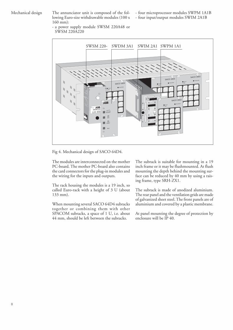
Mechanical design The annunciator unit is composed of the fol-lowing Euro-size withdrawable modules (100 x160 mm):- a power supply module SWSM 220A48 or
SWSM 220A220
- four microprocessor modules SWPM 1A1B- four input/output modules SWIM 2A1B
FAULT
ON
PROGRAM
12
34
56
78
910
1112
1314
1516
FAULT
ON
PROGRAM
12
34
56
78
910
1112
1314
1516
FAULT
ON
PROGRAM
12
34
56
78
910
1112
1314
1516
TEST
RESET
ACK
SILENCE
FAULT
ON
PROGRAM
23
4
67
8
1011
12
1415
16
1
5
9
13
SACO 16D2
SACO 16D2
SACO 16D2SACO 16D2
SWPM 1A1SWIM 2A1SWSM 220- SWDM 3A1
Fig 4. Mechanical design of SACO 64D4.
The modules are interconnected on the motherPC-board. The mother PC-board also containsthe card connectors for the plug-in modules andthe wiring for the inputs and outputs.
The rack housing the modules is a 19 inch, socalled Euro-rack with a height of 3 U (about133 mm).
When mounting several SACO 64D4 subrackstogether or combining them with otherSPACOM subracks, a space of 1 U, i.e. about44 mm, should be left between the subracks.
The subrack is suitable for mounting in a 19inch frame or it may be flushmounted. At flushmounting the depth behind the mounting sur-face can be reduced by 40 mm by using a rais-ing frame, type SRH-ZX1.
The subrack is made of anodized aluminium.The rear panel and the ventilation grids are madeof galvanized sheet steel. The front panels are ofaluminium and covered by a plastic membrane.
At panel mounting the degree of protection byenclosure will be IP 40.
9
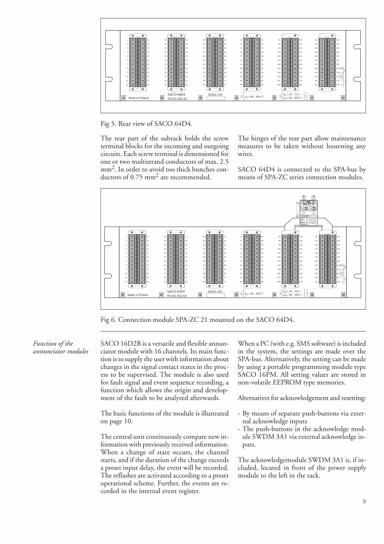
Fig 5. Rear view of SACO 64D4.
The rear part of the subrack holds the screwterminal blocks for the incoming and outgoingcircuits. Each screw terminal is dimensioned forone or two multistrand conductors of max. 2.5mm2. In order to avoid too thick bunches con-ductors of 0.75 mm2 are recommended.
The hinges of the rear part allow maintenancemeasures to be taken without loosening anywires.
SACO 64D4 is connected to the SPA-bus bymeans of SPA-ZC series connection modules.
Fig 6. Connection module SPA-ZC 21 mounted on the SACO 64D4.
Function of theannunciator modules
SACO 16D2B is a versatile and flexible annun-ciator module with 16 channels. Its main func-tion is to supply the user with information aboutchanges in the signal contact states in the proc-ess to be supervised. The module is also usedfor fault signal and event sequence recording, afunction which allows the origin and develop-ment of the fault to be analyzed afterwards.
The basic functions of the module is illustratedon page 10.
The central unit continuously compare new in-formation with previously received information.When a change of state occurs, the channelstarts, and if the duration of the change exceedsa preset input delay, the event will be recorded.The reflashes are activated according to a presetoperational scheme. Further, the events are re-corded in the internal event register.
When a PC (with e.g. SMS software) is includedin the system, the settings are made over theSPA-bus. Alternatively, the setting can be madeby using a portable programming module typeSACO 16PM. All setting values are stored innon-volatile EEPROM type memories.
Alternatives for acknowledgement and resetting:
- By means of separate push-buttons via exter-nal acknowledge inputs
- The push-buttons in the acknowledge mod-ule SWDM 3A1 via external acknowledge in-puts.
The acknowledgemodule SWDM 3A1 is, if in-cluded, located in front of the power supplymodule to the left in the rack.
1 13
2 14
3 15
4 16
5 17
6 18
7 19
8 20
9 21
10 22
11 23
12 24
25 37
26 38
27 39
28 40
29 41
30 42
31 43
32 44
33 45
34 46
35 47
36 48
49 61
50 62
51 63
52 64
53 65
54 66
55 67
56 68
57 69
58 70
59 71
60 72
73 85
74 86
75 87
76 88
77 89
78 90
79 91
80 92
81 93
82 94
83 95
84 96
97 109
98 110
99 111
100 112
101 113
102 114
103 115
104 116
105 117
106 118
107 119
108 120
121 133
122 134
123 135
124 136
125 137
126 138
127 139
128 140
129 141
130 142
131 143
132 144
SERIAL NOMade in Finland
SACO 64D4RS 811 653-AA
2 1UN = 80…265 V ~UN = 19…70 VUN = 80…265 V
1 13
2 14
3 15
4 16
5 17
6 18
7 19
8 20
9 21
10 22
11 23
12 24
25 37
26 38
27 39
28 40
29 41
30 42
31 43
32 44
33 45
34 46
35 47
36 48
49 61
50 62
51 63
52 64
53 65
54 66
55 67
56 68
57 69
58 70
59 71
60 72
73 85
74 86
75 87
76 88
77 89
78 90
79 91
80 92
81 93
82 94
83 95
84 96
97 109
98 110
99 111
100 112
101 113
102 114
103 115
104 116
105 117
106 118
107 119
108 120
121 133
122 134
123 135
124 136
125 137
126 138
127 139
128 140
129 141
130 142
131 143
132 144
SERIAL NO
SPA1 1 0 0
RS4850 0 1 1
1S
0M
SPA-ZC 21BBBM
MBMM
RS 951 021-
Tx Rx
1 5432
-----OPEN-----
Made in FinlandSACO 64D4RS 811 653-AA
2 1UN = 80…265 V ~UN = 19…70 VUN = 80…265 V
10
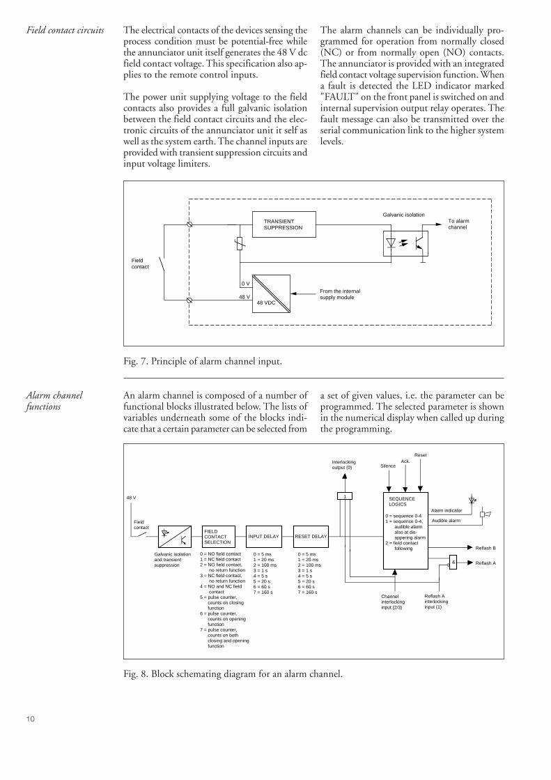
Field contact circuits The electrical contacts of the devices sensing theprocess condition must be potential-free whilethe annunciator unit itself generates the 48 V dcfield contact voltage. This specification also ap-plies to the remote control inputs.
The power unit supplying voltage to the fieldcontacts also provides a full galvanic isolationbetween the field contact circuits and the elec-tronic circuits of the annunciator unit it self aswell as the system earth. The channel inputs areprovided with transient suppression circuits andinput voltage limiters.
The alarm channels can be individually pro-grammed for operation from normally closed(NC) or from normally open (NO) contacts.The annunciator is provided with an integratedfield contact voltage supervision function. Whena fault is detected the LED indicator marked"FAULT" on the front panel is switched on andinternal supervision output relay operates. Thefault message can also be transmitted over theserial communication link to the higher systemlevels.
TRANSIENTSUPPRESSION
To alarmchannel
48 VDC
From the internalsupply module
0 V
48 V
Field contact
Galvanic isolation
Fig. 7. Principle of alarm channel input.
Alarm channelfunctions
An alarm channel is composed of a number offunctional blocks illustrated below. The lists ofvariables underneath some of the blocks indi-cate that a certain parameter can be selected from
a set of given values, i.e. the parameter can beprogrammed. The selected parameter is shownin the numerical display when called up duringthe programming.
Fig. 8. Block schemating diagram for an alarm channel.
SEQUENCELOGICS
Reflash B
& Reflash A
Interlocking output (0)
Ack.Reset
1
Alarm indicator
Audible alarm
Reflash Ainterlockinginput (1)
Channel interlockinginput (2/3)
FIELD CONTACTSELECTION
INPUT DELAY RESET DELAY
48 V
Fieldcontact
Galvanic isolationand transientsuppression
0 = NO field contact1 = NC field contact2 = NO field contact, no return function3 = NC field contact, no return function4 = NO and NC field contact5 = pulse counter, counts on closing function6 = pulse counter, counts on opening function7 = pulse counter, counts on both closing and opening function
0 = 5 ms1 = 20 ms2 = 100 ms3 = 1 s4 = 5 s5 = 20 s6 = 60 s7 = 160 s
0 = 5 ms1 = 20 ms2 = 100 ms3 = 1 s4 = 5 s5 = 20 s6 = 60 s7 = 160 s
-
0 = sequence 0-41 = sequence 0-4, audible alarm also at dis- appering alarm2 = field contact following
Silence
11
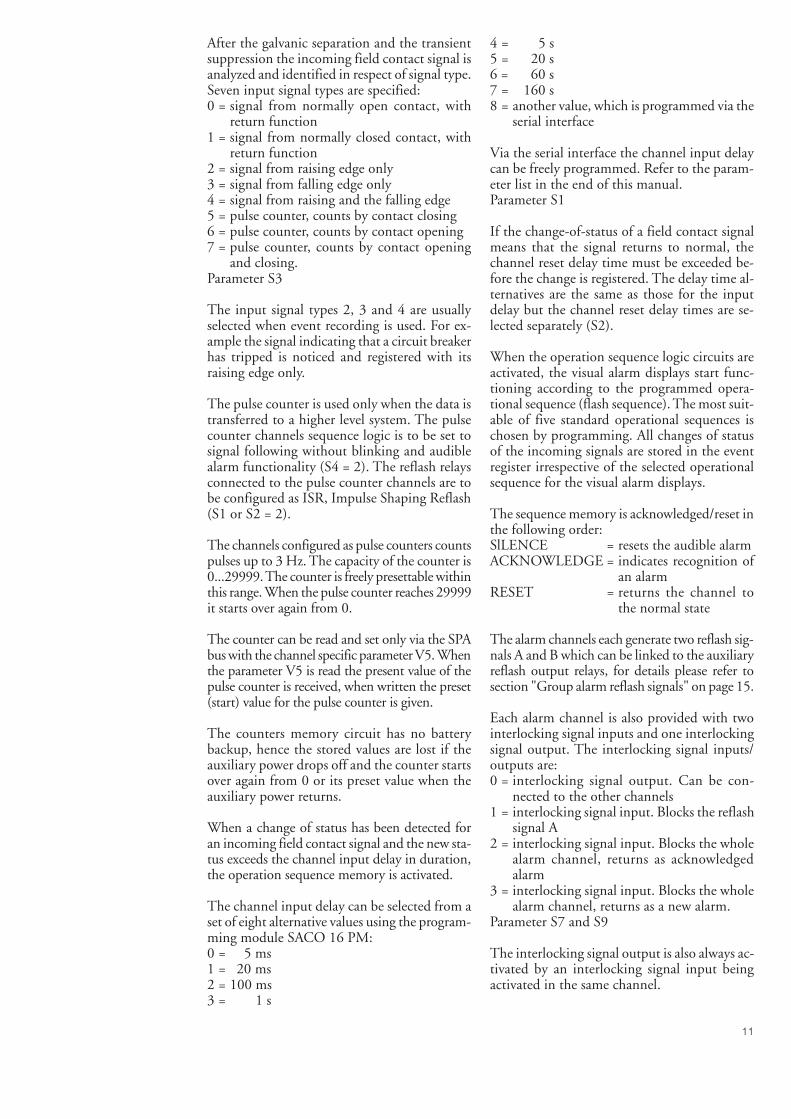
After the galvanic separation and the transientsuppression the incoming field contact signal isanalyzed and identified in respect of signal type.Seven input signal types are specified:0 = signal from normally open contact, with
return function1 = signal from normally closed contact, with
return function2 = signal from raising edge only3 = signal from falling edge only4 = signal from raising and the falling edge5 = pulse counter, counts by contact closing6 = pulse counter, counts by contact opening7 = pulse counter, counts by contact opening
and closing.Parameter S3
The input signal types 2, 3 and 4 are usuallyselected when event recording is used. For ex-ample the signal indicating that a circuit breakerhas tripped is noticed and registered with itsraising edge only.
The pulse counter is used only when the data istransferred to a higher level system. The pulsecounter channels sequence logic is to be set tosignal following without blinking and audiblealarm functionality (S4 = 2). The reflash relaysconnected to the pulse counter channels are tobe configured as ISR, Impulse Shaping Reflash(S1 or S2 = 2).
The channels configured as pulse counters countspulses up to 3 Hz. The capacity of the counter is0...29999. The counter is freely presettable withinthis range. When the pulse counter reaches 29999it starts over again from 0.
The counter can be read and set only via the SPAbus with the channel specific parameter V5. Whenthe parameter V5 is read the present value of thepulse counter is received, when written the preset(start) value for the pulse counter is given.
The counters memory circuit has no batterybackup, hence the stored values are lost if theauxiliary power drops off and the counter startsover again from 0 or its preset value when theauxiliary power returns.
When a change of status has been detected foran incoming field contact signal and the new sta-tus exceeds the channel input delay in duration,the operation sequence memory is activated.
The channel input delay can be selected from aset of eight alternative values using the program-ming module SACO 16 PM:0 = 5 ms1 = 20 ms2 = 100 ms3 = 1 s
4 = 5 s5 = 20 s6 = 60 s7 = 160 s8 = another value, which is programmed via the
serial interface
Via the serial interface the channel input delaycan be freely programmed. Refer to the param-eter list in the end of this manual.Parameter S1
If the change-of-status of a field contact signalmeans that the signal returns to normal, thechannel reset delay time must be exceeded be-fore the change is registered. The delay time al-ternatives are the same as those for the inputdelay but the channel reset delay times are se-lected separately (S2).
When the operation sequence logic circuits areactivated, the visual alarm displays start func-tioning according to the programmed opera-tional sequence (flash sequence). The most suit-able of five standard operational sequences ischosen by programming. All changes of statusof the incoming signals are stored in the eventregister irrespective of the selected operationalsequence for the visual alarm displays.
The sequence memory is acknowledged/reset inthe following order:SlLENCE = resets the audible alarmACKNOWLEDGE = indicates recognition of
an alarmRESET = returns the channel to
the normal state
The alarm channels each generate two reflash sig-nals A and B which can be linked to the auxiliaryreflash output relays, for details please refer tosection "Group alarm reflash signals" on page 15.
Each alarm channel is also provided with twointerlocking signal inputs and one interlockingsignal output. The interlocking signal inputs/outputs are:0 = interlocking signal output. Can be con-
nected to the other channels1 = interlocking signal input. Blocks the reflash
signal A2 = interlocking signal input. Blocks the whole
alarm channel, returns as acknowledgedalarm
3 = interlocking signal input. Blocks the wholealarm channel, returns as a new alarm.
Parameter S7 and S9
The interlocking signal output is also always ac-tivated by an interlocking signal input beingactivated in the same channel.
12
Visual alarmindication
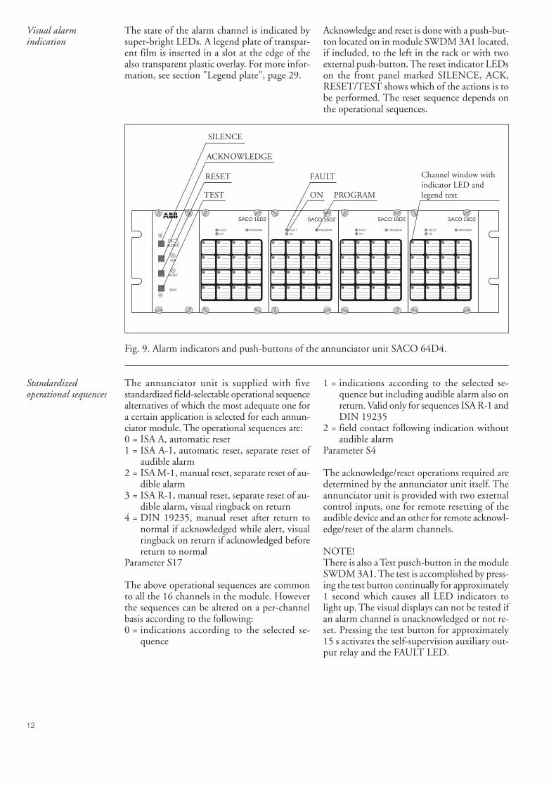
The state of the alarm channel is indicated bysuper-bright LEDs. A legend plate of transpar-ent film is inserted in a slot at the edge of thealso transparent plastic overlay. For more infor-mation, see section "Legend plate", page 29.
Acknowledge and reset is done with a push-but-ton located on in module SWDM 3A1 located,if included, to the left in the rack or with twoexternal push-button. The reset indicator LEDson the front panel marked SILENCE, ACK,RESET/TEST shows which of the actions is tobe performed. The reset sequence depends onthe operational sequences.
FAULT
ON
PROGRAM
1 2 3 4
5 6 7 8
9 10 11 12
13 14 15 16TEST
RESET
ACK
SILENCE
FAULT
ON
PROGRAM
1 2 3 4
5 6 7 8
9 10 11 12
13 14 15 16
FAULT
ON
PROGRAM
1 2 3 4
5 6 7 8
9 10 11 12
13 14 15 16
FAULT
ON
PROGRAM
1 2 3 4
5 6 7 8
9 10 11 12
13 14 15 16
SACO 16D2 SACO 16D2 SACO 16D2 SACO 16D2
Channel window withindicator LED andlegend textPROGRAMON
FAULT
SILENCE
ACKNOWLEDGE
RESET
TEST
Fig. 9. Alarm indicators and push-buttons of the annunciator unit SACO 64D4.
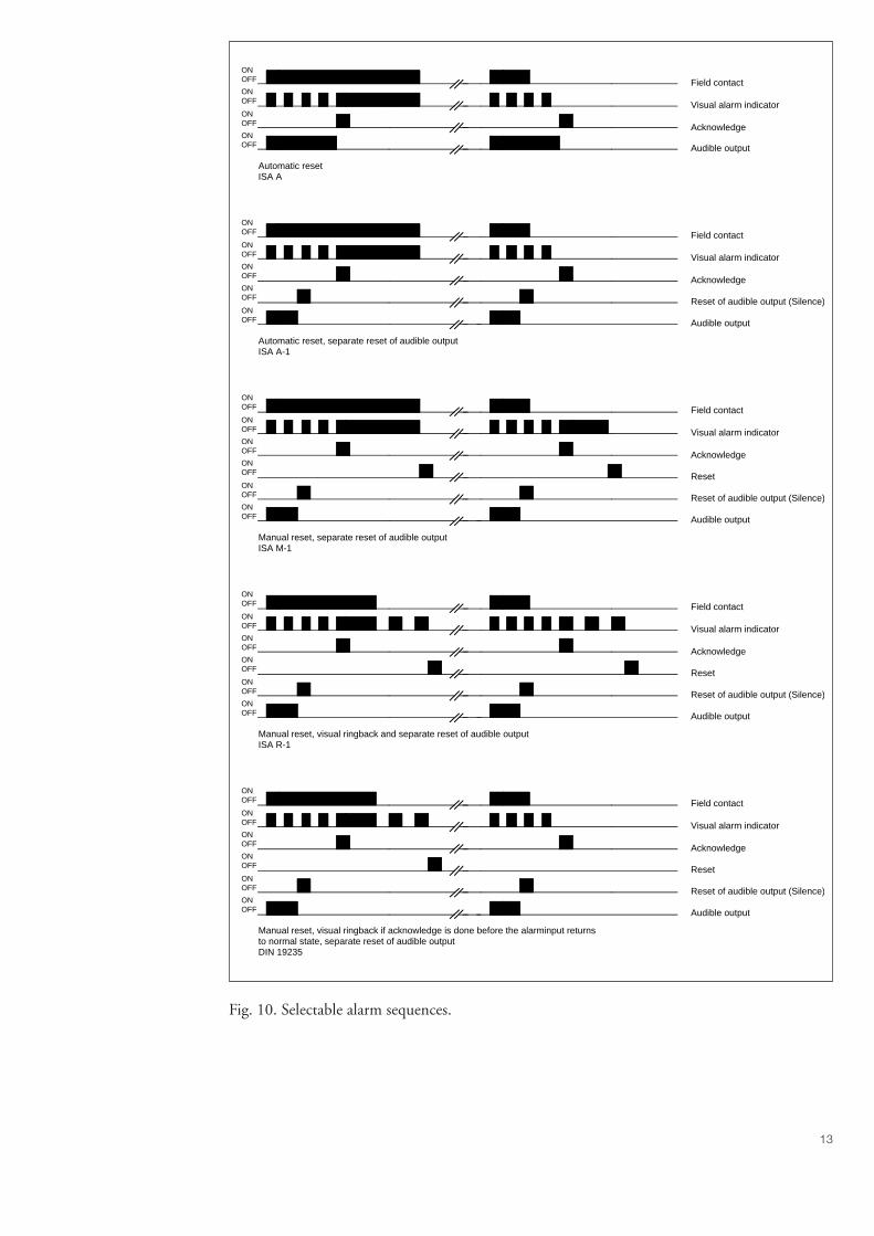
Standardizedoperational sequences
The annunciator unit is supplied with fivestandardized field-selectable operational sequencealternatives of which the most adequate one fora certain application is selected for each annun-ciator module. The operational sequences are:0 = ISA A, automatic reset1 = ISA A-1, automatic reset, separate reset of
audible alarm2 = ISA M-1, manual reset, separate reset of au-
dible alarm3 = ISA R-1, manual reset, separate reset of au-
dible alarm, visual ringback on return4 = DIN 19235, manual reset after return to
normal if acknowledged while alert, visualringback on return if acknowledged beforereturn to normal
Parameter S17
The above operational sequences are commonto all the 16 channels in the module. Howeverthe sequences can be altered on a per-channelbasis according to the following:0 = indications according to the selected se-
quence
1 = indications according to the selected se-quence but including audible alarm also onreturn. Valid only for sequences ISA R-1 andDIN 19235
2 = field contact following indication withoutaudible alarm
Parameter S4
The acknowledge/reset operations required aredetermined by the annunciator unit itself. Theannunciator unit is provided with two externalcontrol inputs, one for remote resetting of theaudible device and an other for remote acknowl-edge/reset of the alarm channels.
NOTE!There is also a Test pusch-button in the moduleSWDM 3A1. The test is accomplished by press-ing the test button continually for approximately1 second which causes all LED indicators tolight up. The visual displays can not be tested ifan alarm channel is unacknowledged or not re-set. Pressing the test button for approximately15 s activates the self-supervision auxiliary out-put relay and the FAULT LED.
13
Automatic resetISA A
ONOFF
ONOFF
ONOFF
ONOFF
ONOFF
ONOFF
ONOFF
ONOFF
ONOFF
ONOFF
ONOFF
ONOFF
ONOFF
ONOFF
ONOFF
ONOFF
ONOFF
ONOFF
ONOFF
ONOFF
ONOFF
Field contact
Acknowledge
Reset of audible output (Silence)
Audible output
Field contact
Visual alarm indicator
Acknowledge
Audible output
Field contact
Visual alarm indicator
Acknowledge
Reset of audible output (Silence)
Audible output
Reset
Field contact
Visual alarm indicator
Acknowledge
Reset of audible output (Silence)
Audible output
Reset
Field contact
Visual alarm indicator
Acknowledge
Reset of audible output (Silence)
Audible output
Reset
Automatic reset, separate reset of audible outputISA A-1
Manual reset, separate reset of audible outputISA M-1
Manual reset, visual ringback and separate reset of audible output ISA R-1
Manual reset, visual ringback if acknowledge is done before the alarminput returnsto normal state, separate reset of audible outputDIN 19235
ONOFF
ONOFF
ONOFF
ONOFF
ONOFF
ONOFF
Visual alarm indicator
Fig. 10. Selectable alarm sequences.
14
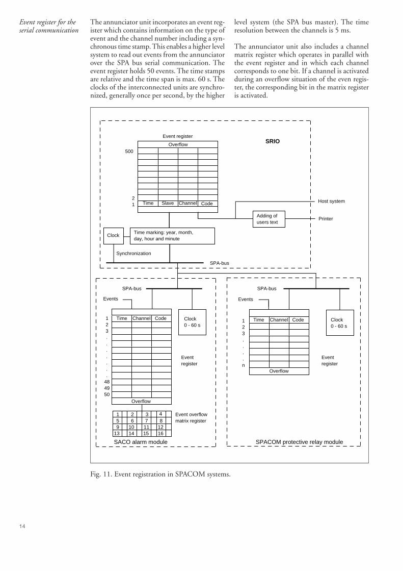
Event register for theserial communication
The annunciator unit incorporates an event reg-ister which contains information on the type ofevent and the channel number including a syn-chronous time stamp. This enables a higher levelsystem to read out events from the annunciatorover the SPA bus serial communication. Theevent register holds 50 events. The time stampsare relative and the time span is max. 60 s. Theclocks of the interconnected units are synchro-nized, generally once per second, by the higher
level system (the SPA bus master). The timeresolution between the channels is 5 ms.
The annunciator unit also includes a channelmatrix register which operates in parallel withthe event register and in which each channelcorresponds to one bit. If a channel is activatedduring an overflow situation of the even regis-ter, the corresponding bit in the matrix registeris activated.
Overflow
Overflow
Time Slave Channel Code21
500
Adding of users text
Event register
Clock
SPA-bus
Synchronization
SRIO
Printer
Host systemTime Slave Channel Code
Channel CodeTime
Events
Clock0 - 60 s
SACO alarm module
Eventregister
Overflow
1 2 3 45 6 7 89 10 11
14 16
Event overflow matrix register
SPA-bus
Clock0 - 60 s
Time123....n
Channel Code
Events
SPA-bus
SPACOM protective relay module
Eventregister
1213 15
Time marking: year, month, day, hour and minute
123.......
484950
Fig. 11. Event registration in SPACOM systems.
15
Auxiliary outputs The annunciator includes 16 auxiliary outputrelays. 14 output relays act as group alarm reflashoutput elements, one auxiliary output relay isdedicated for control of an audible device andone relay acts as an auxiliary output element forthe internal self-supervision function. In a cen-tralized system (i.e. when several SACO 64D4are connected together) there might be no needto use the audible sevice output and theselfsupervision output on every unit separately,hence all 16 outputs can be used as Group AlarmReflash outputs.
By using the relay unit SACO 128R4, whichmay accommodate a total of 128 output relays,and which is connected to the annunciatormodules by means of flat cables, a total of 16reflash group outputs, 16 contact doubler out-puts and 16 paralell lamp outputs can be pro-vided from each annunciator module. Theseoutputs can also be grouped by means of thegrouping module SACO 64C5
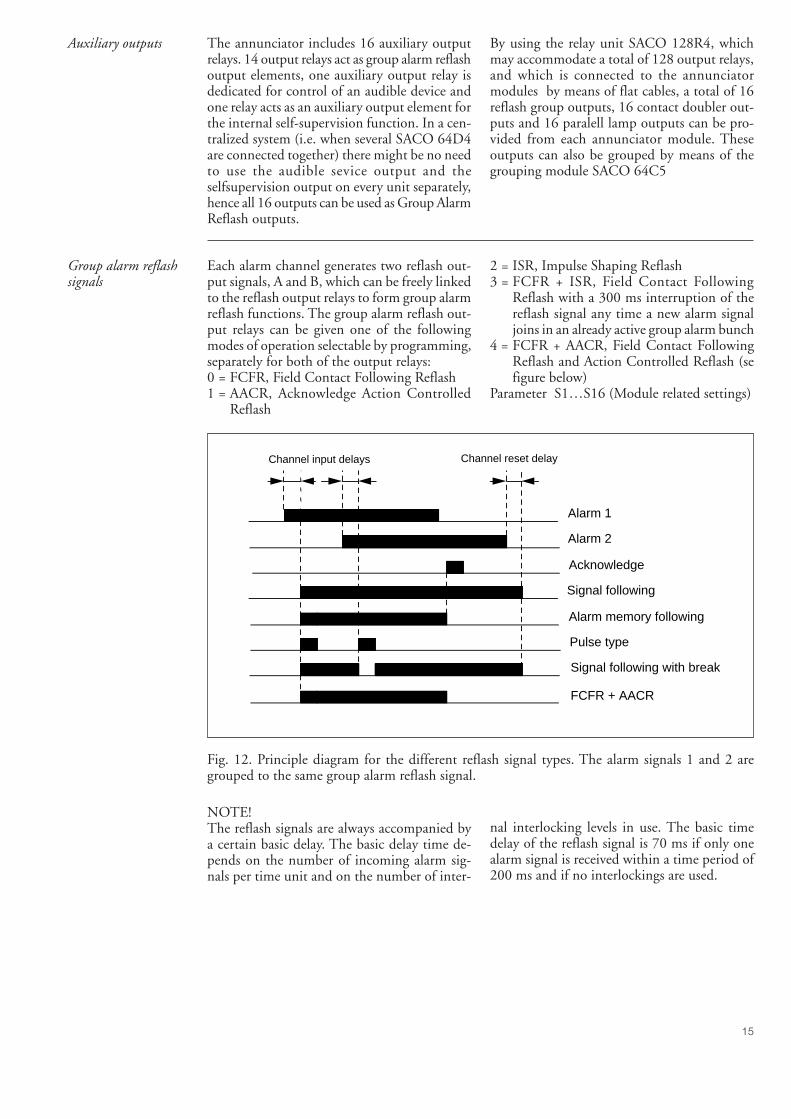
Group alarm reflashsignals
Each alarm channel generates two reflash out-put signals, A and B, which can be freely linkedto the reflash output relays to form group alarmreflash functions. The group alarm reflash out-put relays can be given one of the followingmodes of operation selectable by programming,separately for both of the output relays:0 = FCFR, Field Contact Following Reflash1 = AACR, Acknowledge Action Controlled
Reflash
2 = ISR, Impulse Shaping Reflash3 = FCFR + ISR, Field Contact Following
Reflash with a 300 ms interruption of thereflash signal any time a new alarm signaljoins in an already active group alarm bunch
4 = FCFR + AACR, Field Contact FollowingReflash and Action Controlled Reflash (sefigure below)
Parameter S1…S16 (Module related settings)
Channel input delays Channel reset delay
Alarm 1
Alarm 2
Acknowledge
Signal following
Alarm memory following
Pulse type
Signal following with break
FCFR + AACR
Fig. 12. Principle diagram for the different reflash signal types. The alarm signals 1 and 2 aregrouped to the same group alarm reflash signal.
NOTE!The reflash signals are always accompanied bya certain basic delay. The basic delay time de-pends on the number of incoming alarm sig-nals per time unit and on the number of inter-
nal interlocking levels in use. The basic timedelay of the reflash signal is 70 ms if only onealarm signal is received within a time period of200 ms and if no interlockings are used.
16
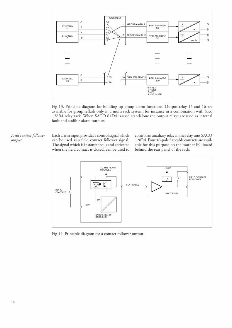
Fig 13. Principle diagram for building up group alarm functions. Output relay 15 and 16 areavailable for group reflash only in a multi rack system, for instance in a combination with Saco128R4 relay rack. When SACO 64D4 is used standalone the output relays are used as internalfault and audible alarm outputs.
CHANNEL1
CHANNEL2
A
B
A
B
S5
S61
S5
S62
GROUPING
REFLASHMODES1
REFLASHMODES2
S5
S6
16CHANNEL
16
A
BREFLASHMODE
S16
0 = VSJ1 = MSJ2 = PJ3 = VSJ + ISR
GROUPALARM 16
GROUPALARM 1
GROUPALARM 2
Field contact followeroutput
Each alarm input provides a control signal whichcan be used as a field contact follower signal.The signal which is instantaneous and activatedwhen the field contact is closed, can be used to
control an auxiliary relay in the relay unit SACO128R4. Four 16-pole flat cable contacts are avail-able for this purpose on the mother PC-boardbehind the rear panel of the rack.
FLAT CABLE
+ 24 V
SACO 128R4
FIELD CONTACTFOLLOWER
TO THE ALARMMODULES
SACO 148D4 ORSACO 64D4
48 V
FIELDCONTACT
0V
Fig 14. Principle diagram for a contact follower output.
17
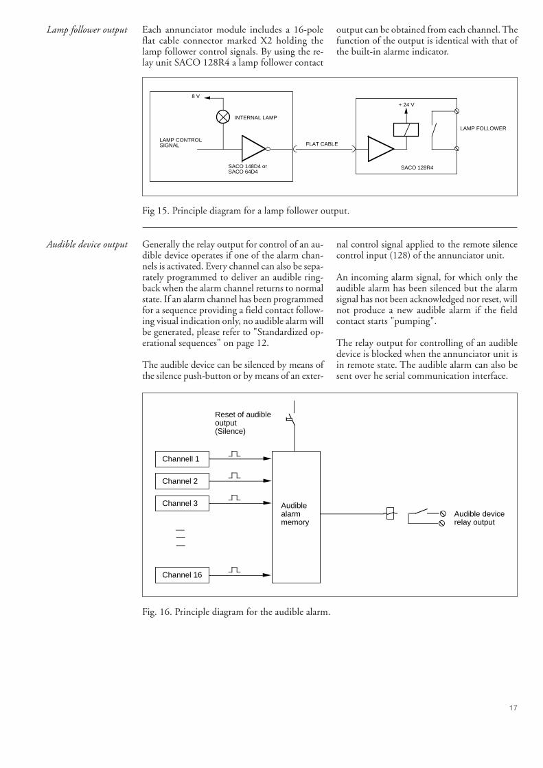
Lamp follower output Each annunciator module includes a 16-poleflat cable connector marked X2 holding thelamp follower control signals. By using the re-lay unit SACO 128R4 a lamp follower contact
output can be obtained from each channel. Thefunction of the output is identical with that ofthe built-in alarme indicator.
FLAT CABLE
+ 24 V
SACO 128R4
LAMP FOLLOWER
8 V
INTERNAL LAMP
LAMP CONTROLSIGNAL
SACO 148D4 orSACO 64D4
Fig 15. Principle diagram for a lamp follower output.
Audible device output Generally the relay output for control of an au-dible device operates if one of the alarm chan-nels is activated. Every channel can also be sepa-rately programmed to deliver an audible ring-back when the alarm channel returns to normalstate. If an alarm channel has been programmedfor a sequence providing a field contact follow-ing visual indication only, no audible alarm willbe generated, please refer to "Standardized op-erational sequences" on page 12.
The audible device can be silenced by means ofthe silence push-button or by means of an exter-
nal control signal applied to the remote silencecontrol input (128) of the annunciator unit.
An incoming alarm signal, for which only theaudible alarm has been silenced but the alarmsignal has not been acknowledged nor reset, willnot produce a new audible alarm if the fieldcontact starts "pumping".
The relay output for controlling of an audibledevice is blocked when the annunciator unit isin remote state. The audible alarm can also besent over he serial communication interface.
Channell 1
Channel 2
Channel 3
Channel 16
Audiblealarmmemory
Reset of audibleoutput(Silence)
Audible devicerelay output
Fig. 16. Principle diagram for the audible alarm.
18
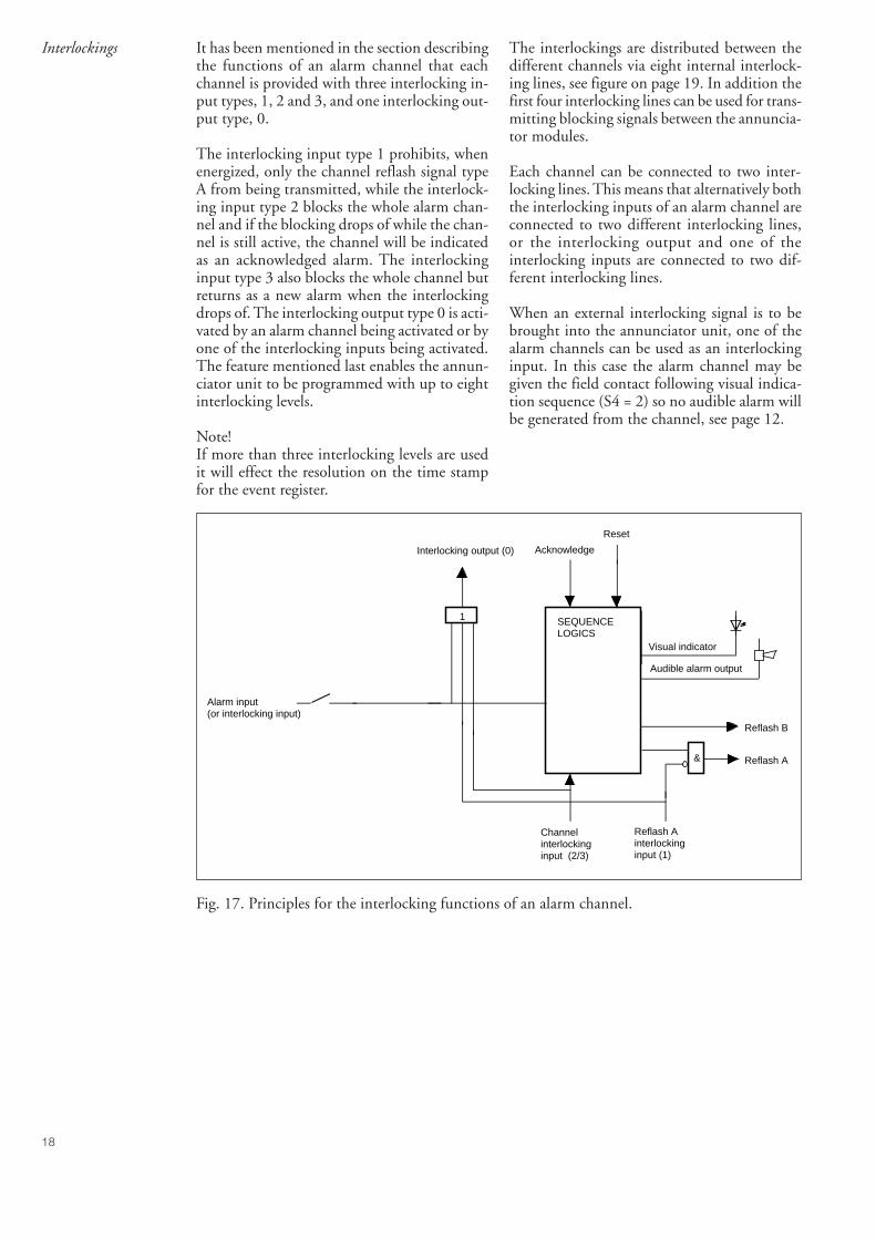
Interlockings It has been mentioned in the section describingthe functions of an alarm channel that eachchannel is provided with three interlocking in-put types, 1, 2 and 3, and one interlocking out-put type, 0.
The interlocking input type 1 prohibits, whenenergized, only the channel reflash signal typeA from being transmitted, while the interlock-ing input type 2 blocks the whole alarm chan-nel and if the blocking drops of while the chan-nel is still active, the channel will be indicatedas an acknowledged alarm. The interlockinginput type 3 also blocks the whole channel butreturns as a new alarm when the interlockingdrops of. The interlocking output type 0 is acti-vated by an alarm channel being activated or byone of the interlocking inputs being activated.The feature mentioned last enables the annun-ciator unit to be programmed with up to eightinterlocking levels.
Note!If more than three interlocking levels are usedit will effect the resolution on the time stampfor the event register.
The interlockings are distributed between thedifferent channels via eight internal interlock-ing lines, see figure on page 19. In addition thefirst four interlocking lines can be used for trans-mitting blocking signals between the annuncia-tor modules.
Each channel can be connected to two inter-locking lines. This means that alternatively boththe interlocking inputs of an alarm channel areconnected to two different interlocking lines,or the interlocking output and one of theinterlocking inputs are connected to two dif-ferent interlocking lines.
When an external interlocking signal is to bebrought into the annunciator unit, one of thealarm channels can be used as an interlockinginput. In this case the alarm channel may begiven the field contact following visual indica-tion sequence (S4 = 2) so no audible alarm willbe generated from the channel, see page 12.
SEQUENCELOGICS
Reflash B
& Reflash A
Interlocking output (0) Acknowledge
Reset
1
Visual indicator
Audible alarm output
Reflash Ainterlockinginput (1)
Channelinterlockinginput (2/3)
Alarm input(or interlocking input)
Fig. 17. Principles for the interlocking functions of an alarm channel.
19
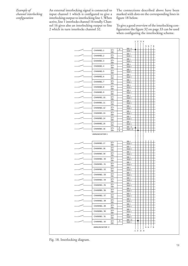
Example ofchannel interlockingconfiguration
An external interlocking signal is connected toinput channel 1 which is configured to give ainterlocking output to interlocking line 1. Whenactive, line 1 interlocks channel 16 totally. Chan-nel 16 gives also an interlocking output to line2 which in turn interlocks channel 32.
The connections described above have beenmarked with dots on the corresponding lines infigure 18 below.
To give a good overview of the interlocking con-figuration the figure 32 on page 33 can be usedwhen configuring the interlocking scheme.
S7=S9=
CHANNEL 1S8 = 1S10 =
S7=S9=
CHANNEL 2S8 =S10 =
S7=S9=
CHANNEL 3S8 =S10 =
S7=S9=
CHANNEL 4S8 =S10 =
S7=S9=
CHANNEL 5S8 =S10 =
S7=S9=
CHANNEL 6S8 =S10 =
S7=S9=
CHANNEL 7S8 =S10 =
S7=S9=
CHANNEL 8S8 =S10 =
S7=S9=
CHANNEL 9S8 =S10 =
S7=S9=
CHANNEL 10 S8 =S10 =
S7=S9=
CHANNEL 11S8 =S10 =
S7=S9=
CHANNEL 12S8 =S10 =
S7=S9=
CHANNEL 13S8 =S10 =
S7=S9=
CHANNEL 14S8 =S10 =
S7=S9=
CHANNEL 15S8 =S10 =
S7=S9=
CHANNEL 16S8 = 1S10 = 2
S7=S9=
CHANNEL 17S8 =S10 =
S7=S9=
CHANNEL 18S8 =S10 =
S7=S9=
CHANNEL 19S8 =S10 =
S7=S9=
CHANNEL 20S8 =S10 =
S7=S9=
CHANNEL 21S8 =S10 =
S7=S9=
CHANNEL 22S8 =S10 =
S7=S9=
CHANNEL 23S8 =S10 =
S7=S9=
CHANNEL 24S8 =S10 =
S7=S9=
CHANNEL 25S8 =S10 =
S7=S9=
CHANNEL 26S8 =S10 =
S7=S9=
CHANNEL 27S8 =S10 =
S7=S9=
CHANNEL 28S8 =S10 =
S7=S9=
CHANNEL 29S8 =S10 =
S7=S9=
CHANNEL 30S8 =S10 =
S7=S9=
CHANNEL 31S8 =S10 =
S7=S9=
CHANNEL 32S8 = 2S10 =
ANNUNCIATOR 1
ANNUNCIATOR 2
1 2 3 4
5 6 7 8
0
2
1 2 3 4
5 6 7 8
2
0
Fig. 18. Interlocking diagram.
20
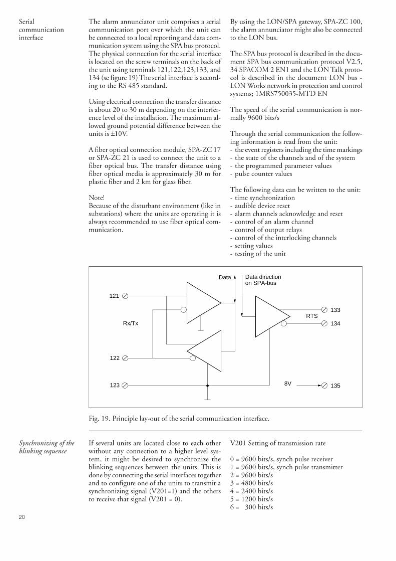
Serialcommunicationinterface
The alarm annunciator unit comprises a serialcommunication port over which the unit canbe connected to a local reporting and data com-munication system using the SPA bus protocol.The physical connection for the serial interfaceis located on the screw terminals on the back ofthe unit using terminals 121,122,123,133, and134 (se figure 19) The serial interface is accord-ing to the RS 485 standard.
Using electrical connection the transfer distanceis about 20 to 30 m depending on the interfer-ence level of the installation. The maximum al-lowed ground potential difference between theunits is ±10V.
A fiber optical connection module, SPA-ZC 17or SPA-ZC 21 is used to connect the unit to afiber optical bus. The transfer distance usingfiber optical media is approximately 30 m forplastic fiber and 2 km for glass fiber.
Note!Because of the disturbant environment (like insubstations) where the units are operating it isalways recommended to use fiber optical com-munication.
By using the LON/SPA gateway, SPA-ZC 100,the alarm annunciator might also be connectedto the LON bus.
The SPA bus protocol is described in the docu-ment SPA bus communication protocol V2.5,34 SPACOM 2 EN1 and the LON Talk proto-col is described in the document LON bus -LON Works network in protection and controlsystems; 1MRS750035-MTD EN
The speed of the serial communication is nor-mally 9600 bits/s
Through the serial communication the follow-ing information is read from the unit:- the event registers including the time markings- the state of the channels and of the system- the programmed parameter values- pulse counter values
The following data can be written to the unit:- time synchronization- audible device reset- alarm channels acknowledge and reset- control of an alarm channel- control of output relays- control of the interlocking channels- setting values- testing of the unit
Fig. 19. Principle lay-out of the serial communication interface.
Synchronizing of theblinking sequence
If several units are located close to each otherwithout any connection to a higher level sys-tem, it might be desired to synchronize theblinking sequences between the units. This isdone by connecting the serial interfaces togetherand to configure one of the units to transmit asynchronizing signal (V201=1) and the othersto receive that signal (V201 = 0).
V201 Setting of transmission rate
0 = 9600 bits/s, synch pulse receiver1 = 9600 bits/s, synch pulse transmitter2 = 9600 bits/s3 = 4800 bits/s4 = 2400 bits/s5 = 1200 bits/s6 = 300 bits/s
8V
RTS
Data Data directionon SPA-bus
Rx/Tx
121
122
123
133
134
135
21
Parameterization The parameter values are stored in the unit in anon-volatile EEPROM memory. Thus the set-ting of parameter values can be performed andchanged by means of the programming moduleSACO 16PM or via the serial communicationusing e.g. the SMS software. This means that
the annunciator unit is fully field-programm-able.
For connecting a PC directly to the serial inter-face of the unit (for parameterization) the ca-bles SPA-ZP 6A3 and SPA-ZP 21A are used.
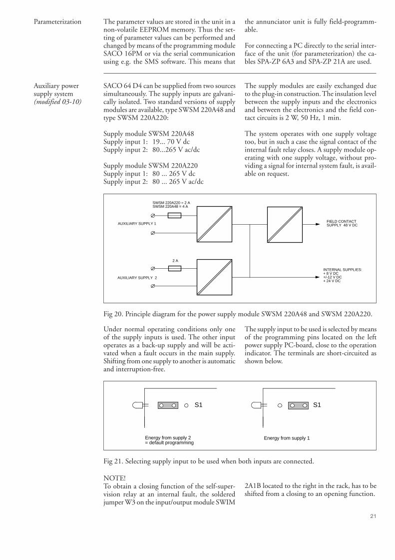
Auxiliary powersupply system(modified 03-10)
SACO 64 D4 can be supplied from two sourcessimultaneously. The supply inputs are galvani-cally isolated. Two standard versions of supplymodules are available, type SWSM 220A48 andtype SWSM 220A220:
Supply module SWSM 220A48Supply input 1: 19... 70 V dcSupply input 2: 80...265 V ac/dc
Supply module SWSM 220A220Supply input 1: 80 ... 265 V dcSupply input 2: 80 ... 265 V ac/dc
The supply modules are easily exchanged dueto the plug-in construction. The insulation levelbetween the supply inputs and the electronicsand between the electronics and the field con-tact circuits is 2 W, 50 Hz, 1 min.
The system operates with one supply voltagetoo, but in such a case the signal contact of theinternal fault relay closes. A supply module op-erating with one supply voltage, without pro-viding a signal for internal system fault, is avail-able on request.
AUXILIARY SUPPLY 1
AUXILIARY SUPPLY 2
2 A
SWSM 220A220 = 2 ASWSM 220A48 = 4 A
FIELD CONTACT SUPPLY 48 V DC
INTERNAL SUPPLIES:+ 8 V DC+/-12 V DC+ 24 V DC
Fig 20. Principle diagram for the power supply module SWSM 220A48 and SWSM 220A220.
Under normal operating conditions only oneof the supply inputs is used. The other inputoperates as a back-up supply and will be acti-vated when a fault occurs in the main supply.Shifting from one supply to another is automaticand interruption-free.
The supply input to be used is selected by meansof the programming pins located on the leftpower supply PC-board, close to the operationindicator. The terminals are short-circuited asshown below.
S1 S1
Energy from supply 2= default programming
Energy from supply 1
Fig 21. Selecting supply input to be used when both inputs are connected.
NOTE!To obtain a closing function of the self-super-vision relay at an internal fault, the solderedjumper W3 on the input/output module SWIM
2A1B located to the right in the rack, has to beshifted from a closing to an opening function.
22
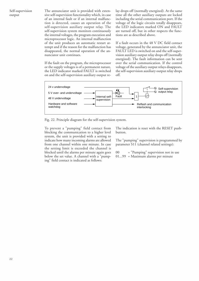
Self-supervisionoutput
The annunciator unit is provided with exten-sive self-supervision functionality which, in caseof an internal fault or if an internal malfunc-tion is detected, causes an operation of theself-supervision auxiliary output relay. Theself-supervision system monitors continuouslythe internal voltages, the program execution andmicroprocessor logic. An internal malfunctionof the unit produces an automatic restart at-tempt and if the reason for the malfunction hasdisappeared, the normal operation of the an-nunciator unit continues.
If the fault on the program, the microprocessoror the supply voltages is of a permanent nature,the LED indicator marked FAULT is switchedon and the self-supervision auxiliary output re-
lay drops off (normally energized). At the sametime all the other auxiliary outputs are lockedincluding the serial communication port. If thevoltage of the logic circuits totally disappears,the LED indicators marked ON and FAULTare turned off, but in other respects the func-tions are as described above.
If a fault occurs in the 48 V DC field contactvoltage, generated by the annunciator unit, theFAULT LED is switched on and the self-super-vision auxiliary output relay drops off (normallyenergized). The fault information can be sentover the serial communication. If the controlvoltage of the auxiliary output relays disappears,the self-supervision auxiliary output relay dropsoff.
Self-supervisionoutput relay
1
Reflash and communicationinterlocking
Internal self-supervision
Fault
24 v undervoltage
5 V over- and undervoltage
48 V undervoltage
Hardware and softwarewatchdog
Fig. 22. Principle diagram for the self-supervision system.
To prevent a "pumping" field contact fromblocking the communication to a higher levelsystem, the unit is provided with a setting toindicate how many incoming alarms are allowedfrom one channel within one minute. In casethe setting limit is exceeded the channel isblocked until the alarms per minute again goesbelow the set value. A channel with a "pump-ing" field contact is indicated as follows:
The indication is reset with the RESET push-button.
The "pumping" supervision is programmed byparameter S11 (channel related settings):
00 = "Pumping" supervision not in use01...99 = Maximum alarms per minute
23
Application
Mounting
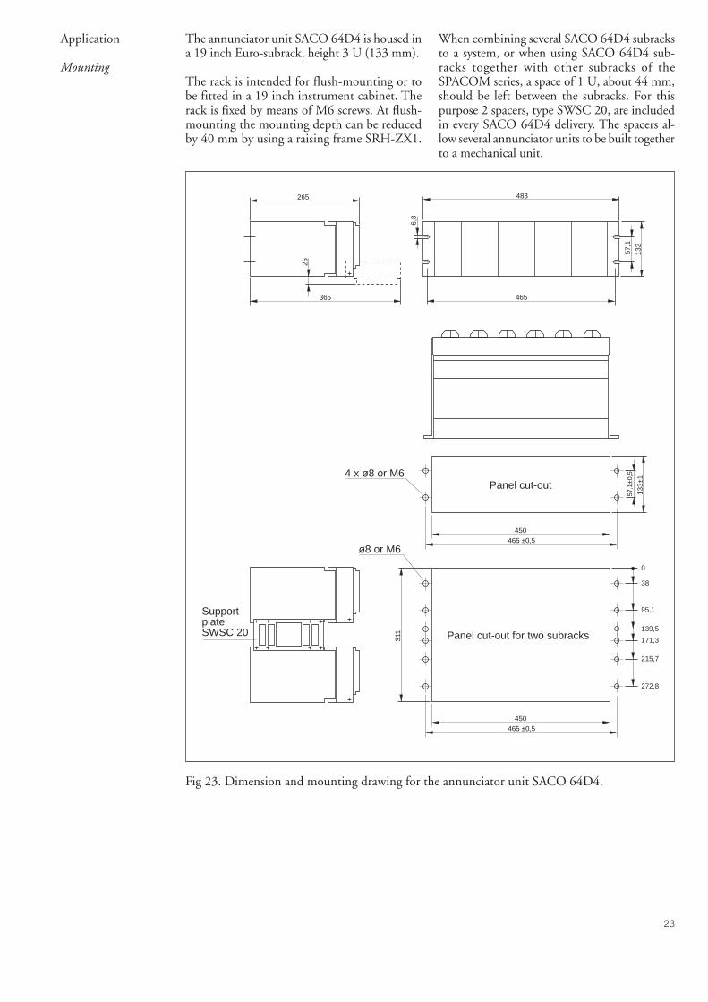
The annunciator unit SACO 64D4 is housed ina 19 inch Euro-subrack, height 3 U (133 mm).
The rack is intended for flush-mounting or tobe fitted in a 19 inch instrument cabinet. Therack is fixed by means of M6 screws. At flush-mounting the mounting depth can be reducedby 40 mm by using a raising frame SRH-ZX1.
When combining several SACO 64D4 subracksto a system, or when using SACO 64D4 sub-racks together with other subracks of theSPACOM series, a space of 1 U, about 44 mm,should be left between the subracks. For thispurpose 2 spacers, type SWSC 20, are includedin every SACO 64D4 delivery. The spacers al-low several annunciator units to be built togetherto a mechanical unit.
365
265
25
311
38
450465 ±0,5
272,8
215,7
171,3
139,5
0
95,1
450465 ±0,5
483
465
6,8
132
57,1
133±
1
57,1
±0,5
SupportplateSWSC 20
4 x ø8 or M6
ø8 or M6
Panel cut-out
Panel cut-out for two subracks
Fig 23. Dimension and mounting drawing for the annunciator unit SACO 64D4.
24
Connection diagram
120 119 118 117 116 115 114 113 112 111 110 109
108 107 106 105 104 103 102 101 100 99 98 97
Reflash
relay 11
Reflash
relay 12
Reflash
relay 13
Reflash
relay 6
Reflash
relay 5
Reflash
relay 14
Reflash
relay 15(Intern.fault)
Reflash
relay 16(A
ud.alarm
)
Reflash
relay 10
Reflash
relay 9
Reflash
relay 8
Reflash
relay 7
144 143 142 141 140 139 138 137 136 135 134 133
132 131 130 129 128 127 126 125 124 123 122 121
+48V
Rx/T
x
SIG
NA
L-G
ND
Reflash
relay 3
Reflash
relay 4
Aud. reset
Ackn.
Reset
Test
+-R
TS
+8V
Reflash
relay 2
+-N -
L +
Reflash
relay 1
Aux.
supply 2
-+A
ux.supply1
96 95 94 93 92 91 90 89 88 87 86 85
84 83 82 81 80 79 78 77 76 75 74 73
CH
1C
H9
CH
2
CH
3
CH
4
CH
5
CH
6
CH
7
CH
8
CH
10
CH
11
CH
12
CH
13
CH
14
CH
15
CH
16
72 71 70 69 68 67 66 65 64 63 62 61
60 59 58 57 56 55 54 53 52 51 50 49
CH
17C
H25
CH
18
CH
19
CH
20
CH
21
CH
22
CH
23
CH
24
CH
26
CH
27
CH
28
CH
29
CH
30
CH
31
CH
32
48 47 46 45 44 43 42 41 40 39 38 37
36 35 34 33 32 31 30 29 28 27 26 25
CH
33C
H41
CH
34
CH
35
CH
36
CH
37
CH
38
CH
39
CH
40
CH
42
CH
43
CH
44
CH
45
CH
46
CH
47
CH
48
24 23 22 21 20 19 18 17 16 15 14 13
12 11 10 9 8 7 6 5 4 3 2 1
CH
49C
H57
CH
50
CH
51
CH
52
CH
53
CH
54
CH
55
CH
56
CH
58
CH
59
CH
60
CH
61
CH
62
CH
63(local)
CH
64(rem
ote)
+48V
+48V
+48V
+48V
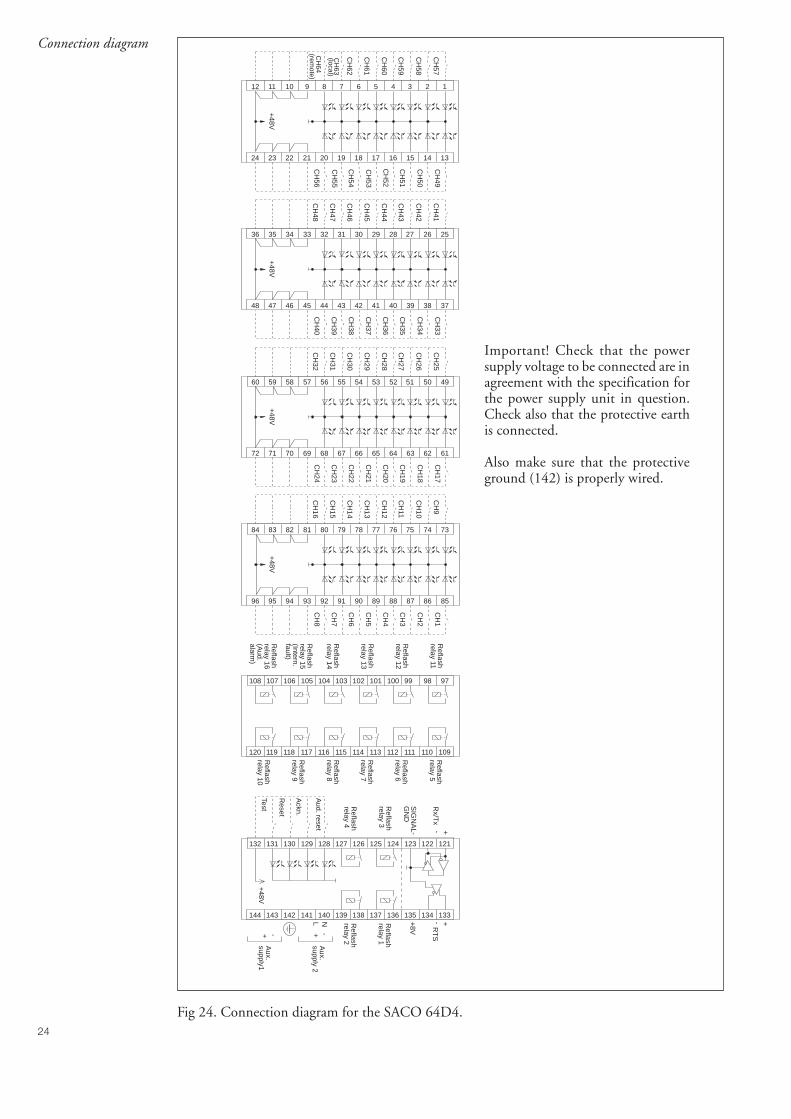
Important! Check that the powersupply voltage to be connected are inagreement with the specification forthe power supply unit in question.Check also that the protective earthis connected.
Also make sure that the protectiveground (142) is properly wired.
Fig 24. Connection diagram for the SACO 64D4.
25
Terminalsand wiring
The screw terminal to facilitate all input andoutput connections are located on the rear panelof the annunciator case. Each screw terminalcan accommodate one or two max. 2.5 mm2
wires. No terminal lugs are needed.
Six terminals are used for connecting theSPA-bus. The connection cable for the fiberoptic SPA-ZC module is attached to these ter-minals.
In an independent system the group alarm No15 can be programmed for internal fault super-vision and the group alarm No 16 for audiblealarm. The programming is made by changingthe jumper position on connector X44. The con-nector is located on the left side of the motherPC-board, seen from the rear.
Function Jumperposition X44
Group alarm output 15 Pin 1-2Group alarm output 16 Pin 4-5Output for audible alarm Pin 5-6Output for internal supervision Pin 2-3
At an internal fault the relay output contactopens. A closing function is obtained by res-oldering a jumper on input/output moduleSWIM 2A1. The module is accessible after re-moving the annunciator module No. 4 to theright.
WARNING!Although the supply voltages are switched offthe output contacts on the input/output mod-ule concerned may contain external voltages.
The two boards can be separated from eachother by pressing the snap-locks on the spacersand then separate them. The programmingjumpers on the relay card are numbered as fol-lows:
W1 = group alarm 13W2 = group alarm 14W3 = group alarm 15/internal faultW4 = group alarm 16/audible alarm
The programming is made by moving thejumper for the concerned relay as illustrated inthe printed scheme on the PC-board, so thatthe required contact function is achieved. Therelay function of the other outputs are repro-grammed in the same way. Every input/outputmodule includes four relays.
The alarm channels 63 and 64 can be repro-grammed to local/remote inputs. Then thechannels 63 and 64 will operate as position in-dicators for the local/remote switch and are tobe programmed for signal following indication(S4 = 2). The programming is made by chang-ing the position of a jumper on connector X45.The connector is found to the left on the motherPCB, seen from the rear.
Function Jumperposition X45
Alarm channel 63 Pin 1-2Alarm channel 64 Pin 4-5Local position (channel 63) Pin 2-3Remote position (channel 64) Pin 5-6
26
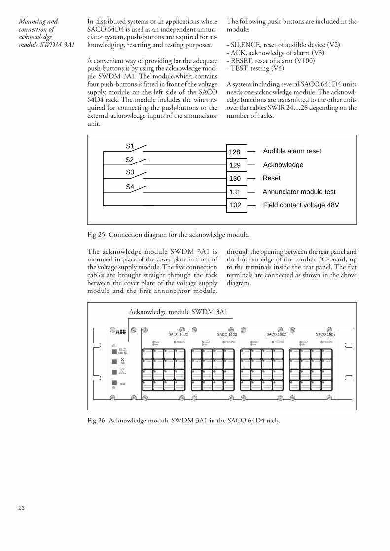
Mounting andconnection ofacknowledgemodule SWDM 3A1
In distributed systems or in applications whereSACO 64D4 is used as an independent annun-ciator system, push-buttons are required for ac-knowledging, resetting and testing purposes.
A convenient way of providing for the adequatepush-buttons is by using the acknowledge mod-ule SWDM 3A1. The module,which containsfour push-buttons is fitted in front of the voltagesupply module on the left side of the SACO64D4 rack. The module includes the wires re-quired for connecting the push-buttons to theexternal acknowledge inputs of the annunciatorunit.
The following push-buttons are included in themodule:
- SILENCE, reset of audible device (V2)- ACK, acknowledge of alarm (V3)- RESET, reset of alarm (V100)- TEST, testing (V4)
A system including several SACO 641D4 unitsneeds one acknowledge module. The acknowl-edge functions are transmitted to the other unitsover flat cables SWIR 24…28 depending on thenumber of racks.
S1
S2
S3
S4
128
129
130
131
132 Field contact voltage 48V
Audible alarm reset
Acknowledge
Reset
Annunciator module test
Fig 25. Connection diagram for the acknowledge module.
The acknowledge module SWDM 3A1 ismounted in place of the cover plate in front ofthe voltage supply module. The five connectioncables are brought straight through the rackbetween the cover plate of the voltage supplymodule and the first annunciator module,
through the opening between the rear panel andthe bottom edge of the mother PC-board, upto the terminals inside the rear panel. The flatterminals are connected as shown in the abovediagram.
FAULT
ON
PROGRAM
1 2 3 4
5 6 7 8
9 10 11 12
13 14 15 16TEST
RESET
ACK
SILENCE
FAULT
ON
PROGRAM
1 2 3 4
5 6 7 8
9 10 11 12
13 14 15 16
FAULT
ON
PROGRAM
1 2 3 4
5 6 7 8
9 10 11 12
13 14 15 16
FAULT
ON
PROGRAM
1 2 3 4
5 6 7 8
9 10 11 12
13 14 15 16
SACO 16D2 SACO 16D2 SACO 16D2 SACO 16D2
Acknowledge module SWDM 3A1
Fig 26. Acknowledge module SWDM 3A1 in the SACO 64D4 rack.
27
Connection to adistributed systemwith or without eventsequence reporting
When connecting a SACO 64D4 to anotherSACO 64D4 or to the control data communica-tor SACO 148D4, they can share the group alarmrelays, the interlocking lines, the self-supervisionrelay and the audible alarm relay.
The units are interconnected by means of a flatcable and the connectors marked X16 on themother PC-board of both units. The cables arebrought in under the rear plate of the unitsthrough the cutout along the lower edge of thepanel. When several units are to be connectedto the SACO 148D4, the flat cables are to bechained together. The following cables are avail-able for the purpose:
Cable type SWIR 24Intermediate cable for two racks
Cable type SWIR 25Intermediate cable for three racks
Cable type SWIR 26Intermediate cable for four racks
Cable type SWIR 27Intermediate cable for five racks
Cable type SWIR 28Intermediate cable for six racks
An already mounted system can be extended byusing a flat cable extension module type SWCM8A1. The extension module is attached to thelast rack and the extension is made with a suit-able cable. The mounting instructions arepacked together with the extension module.
The group alarm reflash functions can be con-nected in parallel by fitting a flat cable to theterminals X21, X22, X23 and X24 of SACO64D4. The cable is then extended to anotherSACO 64D4 or 148D4 to its X21…X24 ter-minals.. From a system united in this way 16group alarm output contacts are obtained. Thetype designation of the cable is SWIR 23.
When the group alarms of several SACO 64D4systems are to be parallelled, the output con-tacts are recommended to be parallelled.
In the last rack of the system the terminatingresistors R1 and R2 of the SPAbus must be con-nected but from the other racks they ought tobe removed. The resistors which are located onthe mother PC-board are connected or discon-necting by means of a jumper on contact X46.R1 is connected by short-circuiting the poles1-2 and R2 is connected by short-circuiting thepoles 4-5.
Connection to adistributed system
The components in the SPACOM system arelinked together, optically, over the SPA-bus.
The higher level system can obtain data for forevent sequence reporting purposes. Remote set-tings can also be performed trough the serialcommunication interface.
For connecting the SACO 64D4 units to thefibre optical loop, bus connection modules areused. SACO 64D4 can be connected both toSPA-bus and LON-bus systems.
28
Connection of a relayoutput extension unittype SACO 128R4
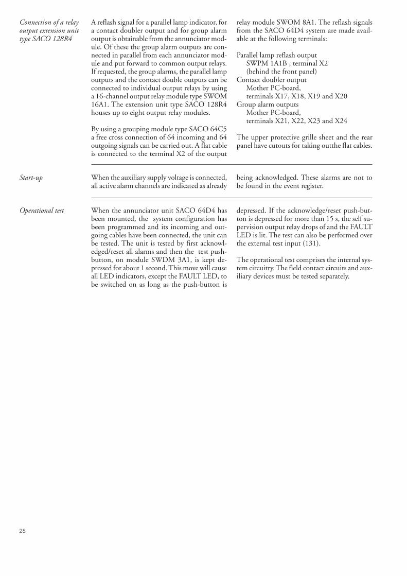
A reflash signal for a parallel lamp indicator, fora contact doubler output and for group alarmoutput is obtainable from the annunciator mod-ule. Of these the group alarm outputs are con-nected in parallel from each annunciator mod-ule and put forward to common output relays.If requested, the group alarms, the parallel lampoutputs and the contact double outputs can beconnected to individual output relays by usinga 16-channel output relay module type SWOM16A1. The extension unit type SACO 128R4houses up to eight output relay modules.
By using a grouping module type SACO 64C5a free cross connection of 64 incoming and 64outgoing signals can be carried out. A flat cableis connected to the terminal X2 of the output
relay module SWOM 8A1. The reflash signalsfrom the SACO 64D4 system are made avail-able at the following terminals:
Parallel lamp reflash outputSWPM 1A1B , terminal X2(behind the front panel)
Contact doubler outputMother PC-board,terminals X17, X18, X19 and X20
Group alarm outputsMother PC-board,terminals X21, X22, X23 and X24
The upper protective grille sheet and the rearpanel have cutouts for taking outthe flat cables.
Start-up When the auxiliary supply voltage is connected,all active alarm channels are indicated as already
being acknowledged. These alarms are not tobe found in the event register.
Operational test When the annunciator unit SACO 64D4 hasbeen mounted, the system configuration hasbeen programmed and its incoming and out-going cables have been connected, the unit canbe tested. The unit is tested by first acknowl-edged/reset all alarms and then the test push-button, on module SWDM 3A1, is kept de-pressed for about 1 second. This move will causeall LED indicators, except the FAULT LED, tobe switched on as long as the push-button is
depressed. If the acknowledge/reset push-but-ton is depressed for more than 15 s, the self su-pervision output relay drops of and the FAULTLED is lit. The test can also be performed overthe external test input (131).
The operational test comprises the internal sys-tem circuitry. The field contact circuits and aux-iliary devices must be tested separately.
29
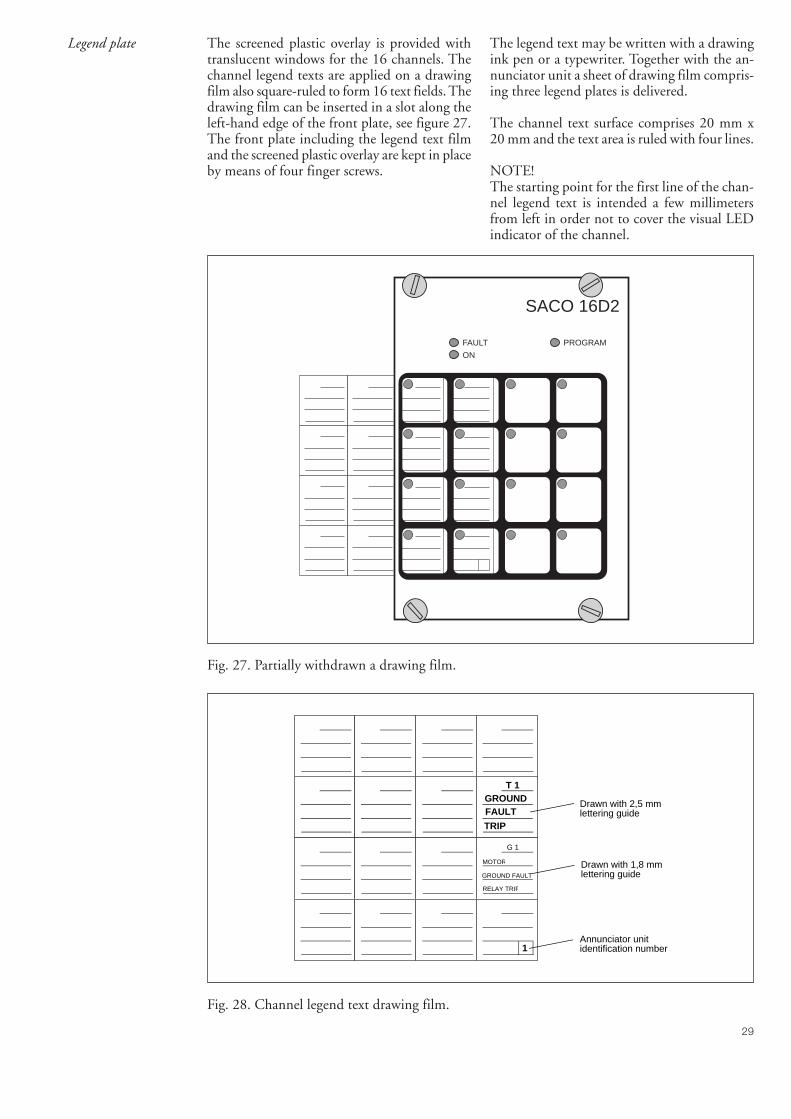
Legend plate The screened plastic overlay is provided withtranslucent windows for the 16 channels. Thechannel legend texts are applied on a drawingfilm also square-ruled to form 16 text fields. Thedrawing film can be inserted in a slot along theleft-hand edge of the front plate, see figure 27.The front plate including the legend text filmand the screened plastic overlay are kept in placeby means of four finger screws.
The legend text may be written with a drawingink pen or a typewriter. Together with the an-nunciator unit a sheet of drawing film compris-ing three legend plates is delivered.
The channel text surface comprises 20 mm x20 mm and the text area is ruled with four lines.
NOTE!The starting point for the first line of the chan-nel legend text is intended a few millimetersfrom left in order not to cover the visual LEDindicator of the channel.
FAULT
ON
PROGRAM
SACO 16D2
T 1GROUNDFAULT
TRIP
G 1
MOTOR
GROUND FAULT
RELAY TRIP
Drawn with 2,5 mm lettering guide
Drawn with 1,8 mm lettering guide
1Annunciator unitidentification number
Fig. 27. Partially withdrawn a drawing film.
Fig. 28. Channel legend text drawing film.
30
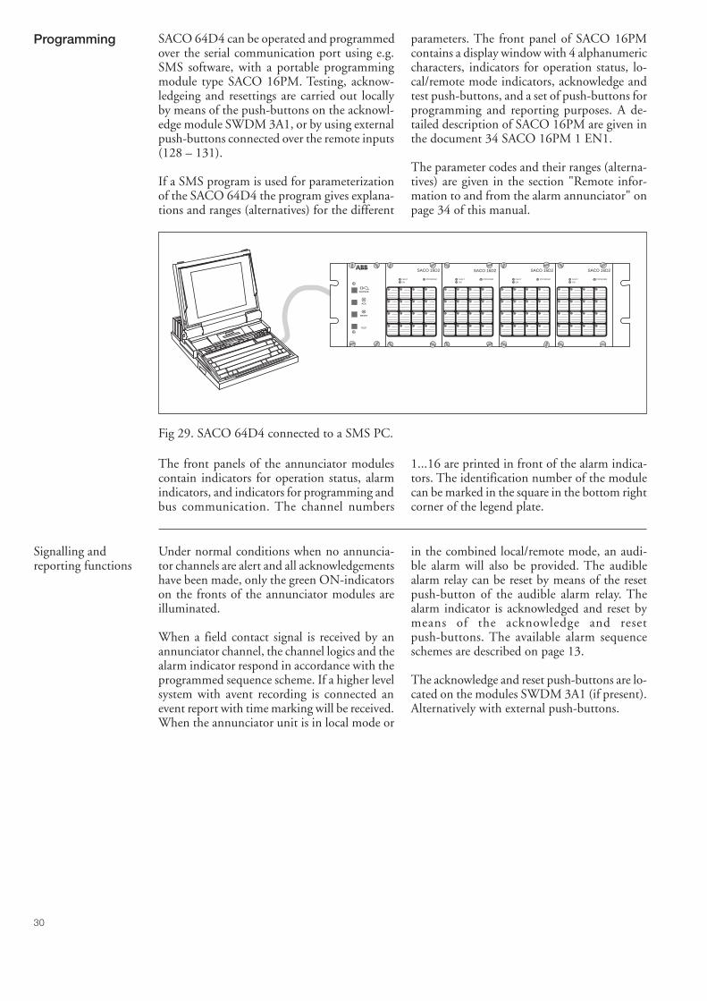
Programming SACO 64D4 can be operated and programmedover the serial communication port using e.g.SMS software, with a portable programmingmodule type SACO 16PM. Testing, acknow-ledgeing and resettings are carried out locallyby means of the push-buttons on the acknowl-edge module SWDM 3A1, or by using externalpush-buttons connected over the remote inputs(128 – 131).
If a SMS program is used for parameterizationof the SACO 64D4 the program gives explana-tions and ranges (alternatives) for the different
parameters. The front panel of SACO 16PMcontains a display window with 4 alphanumericcharacters, indicators for operation status, lo-cal/remote mode indicators, acknowledge andtest push-buttons, and a set of push-buttons forprogramming and reporting purposes. A de-tailed description of SACO 16PM are given inthe document 34 SACO 16PM 1 EN1.
The parameter codes and their ranges (alterna-tives) are given in the section "Remote infor-mation to and from the alarm annunciator" onpage 34 of this manual.
Fig 29. SACO 64D4 connected to a SMS PC.
The front panels of the annunciator modulescontain indicators for operation status, alarmindicators, and indicators for programming andbus communication. The channel numbers
1...16 are printed in front of the alarm indica-tors. The identification number of the modulecan be marked in the square in the bottom rightcorner of the legend plate.
Signalling andreporting functions
Under normal conditions when no annuncia-tor channels are alert and all acknowledgementshave been made, only the green ON-indicatorson the fronts of the annunciator modules areilluminated.
When a field contact signal is received by anannunciator channel, the channel logics and thealarm indicator respond in accordance with theprogrammed sequence scheme. If a higher levelsystem with avent recording is connected anevent report with time marking will be received.When the annunciator unit is in local mode or
in the combined local/remote mode, an audi-ble alarm will also be provided. The audiblealarm relay can be reset by means of the resetpush-button of the audible alarm relay. Thealarm indicator is acknowledged and reset bymeans of the acknowledge and resetpush-buttons. The available alarm sequenceschemes are described on page 13.
The acknowledge and reset push-buttons are lo-cated on the modules SWDM 3A1 (if present).Alternatively with external push-buttons.
FAULT
ON
PROGRAM
1 2 3 4
5 6 7 8
9 10 11 12
13 14 15 16TEST
RESET
ACK
SILENCE
FAULT
ON
PROGRAM
1 2 3 4
5 6 7 8
9 10 11 12
13 14 15 16
FAULT
ON
PROGRAM
1 2 3 4
5 6 7 8
9 10 11 12
13 14 15 16
FAULT
ON
PROGRAM
1 2 3 4
5 6 7 8
9 10 11 12
13 14 15 16
SACO 16D2 SACO 16D2 SACO 16D2 SACO 16D2
31
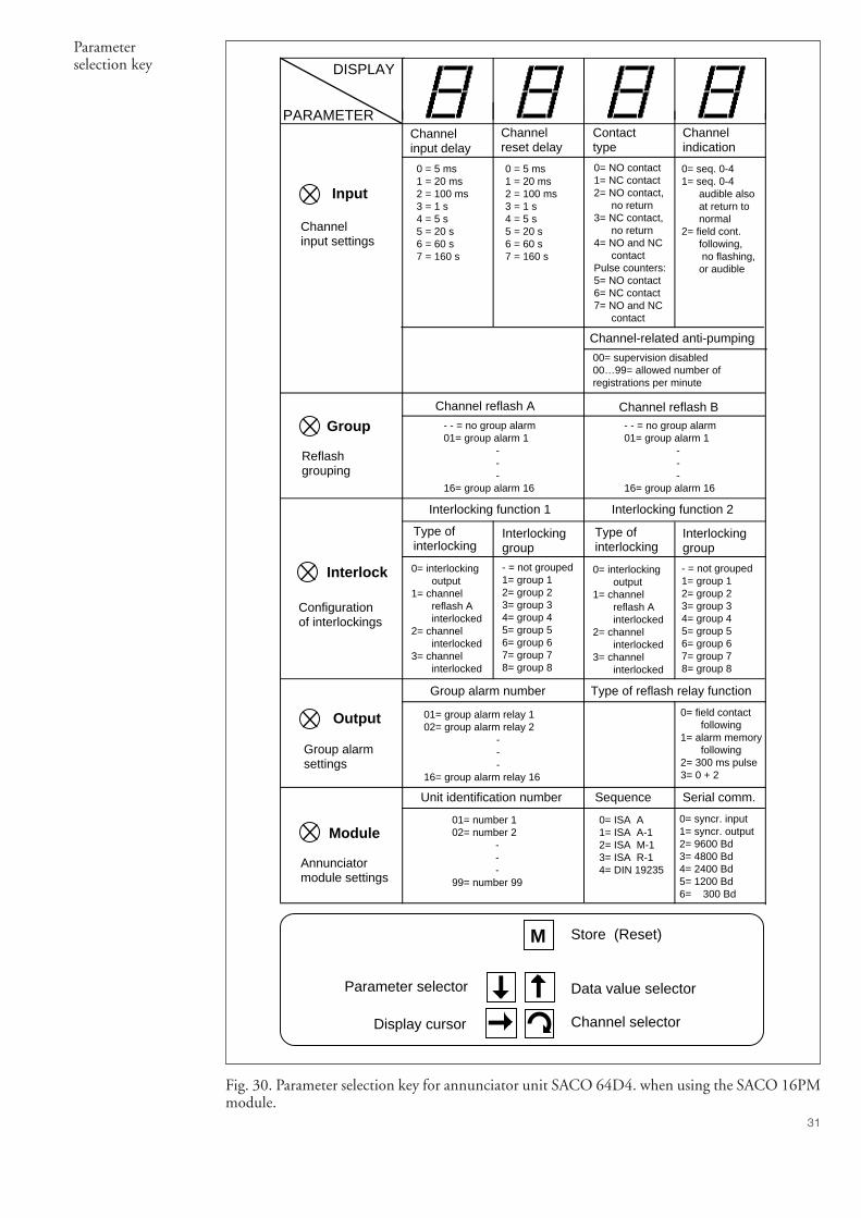
Parameterselection key
Channelinput delay
Channelreset delay
Contacttype
Channelindication
0 = 5 ms1 = 20 ms2 = 100 ms3 = 1 s4 = 5 s5 = 20 s6 = 60 s7 = 160 s
0 = 5 ms1 = 20 ms2 = 100 ms3 = 1 s4 = 5 s5 = 20 s6 = 60 s7 = 160 s
0= NO contact1= NC contact2= NO contact, no return3= NC contact, no return4= NO and NC contact Pulse counters:5= NO contact6= NC contact7= NO and NC contact
0= seq. 0-41= seq. 0-4 audible also at return to normal2= field cont. following, no flashing, or audible
DISPLAY
PARAMETER
Input
Channel reflash A Channel reflash B- - = no group alarm01= group alarm 1 - - -16= group alarm 16
- - = no group alarm01= group alarm 1 - - -16= group alarm 16
Interlocking function 1 Interlocking function 2
Type ofinterlocking
Interlockinggroup
Type ofinterlocking
Interlockinggroup
0= interlocking output1= channel reflash A interlocked2= channel interlocked3= channel interlocked
- = not grouped1= group 12= group 23= group 34= group 45= group 56= group 67= group 78= group 8
0= interlocking output1= channel reflash A interlocked2= channel interlocked3= channel interlocked
- = not grouped1= group 12= group 23= group 34= group 45= group 56= group 67= group 78= group 8
Group alarm number Type of reflash relay function
01= group alarm relay 102= group alarm relay 2 - - -16= group alarm relay 16
0= field contact following1= alarm memory following2= 300 ms pulse3= 0 + 2
Unit identification number Sequence Serial comm.
01= number 102= number 2 - - -99= number 99
0= ISA A1= ISA A-12= ISA M-13= ISA R-14= DIN 19235
0= syncr. input1= syncr. output2= 9600 Bd3= 4800 Bd4= 2400 Bd5= 1200 Bd6= 300 Bd
Group
Interlock
Output
Module
Parameter selector
Display cursor Channel selector
M
Data value selector
Store (Reset)
Channelinput settings
Channel-related anti-pumping
00= supervision disabled00…99= allowed number ofregistrations per minute
Reflashgrouping
Configurationof interlockings
Group alarm settings
Annunciator module settings
Fig. 30. Parameter selection key for annunciator unit SACO 64D4. when using the SACO 16PMmodule.
32
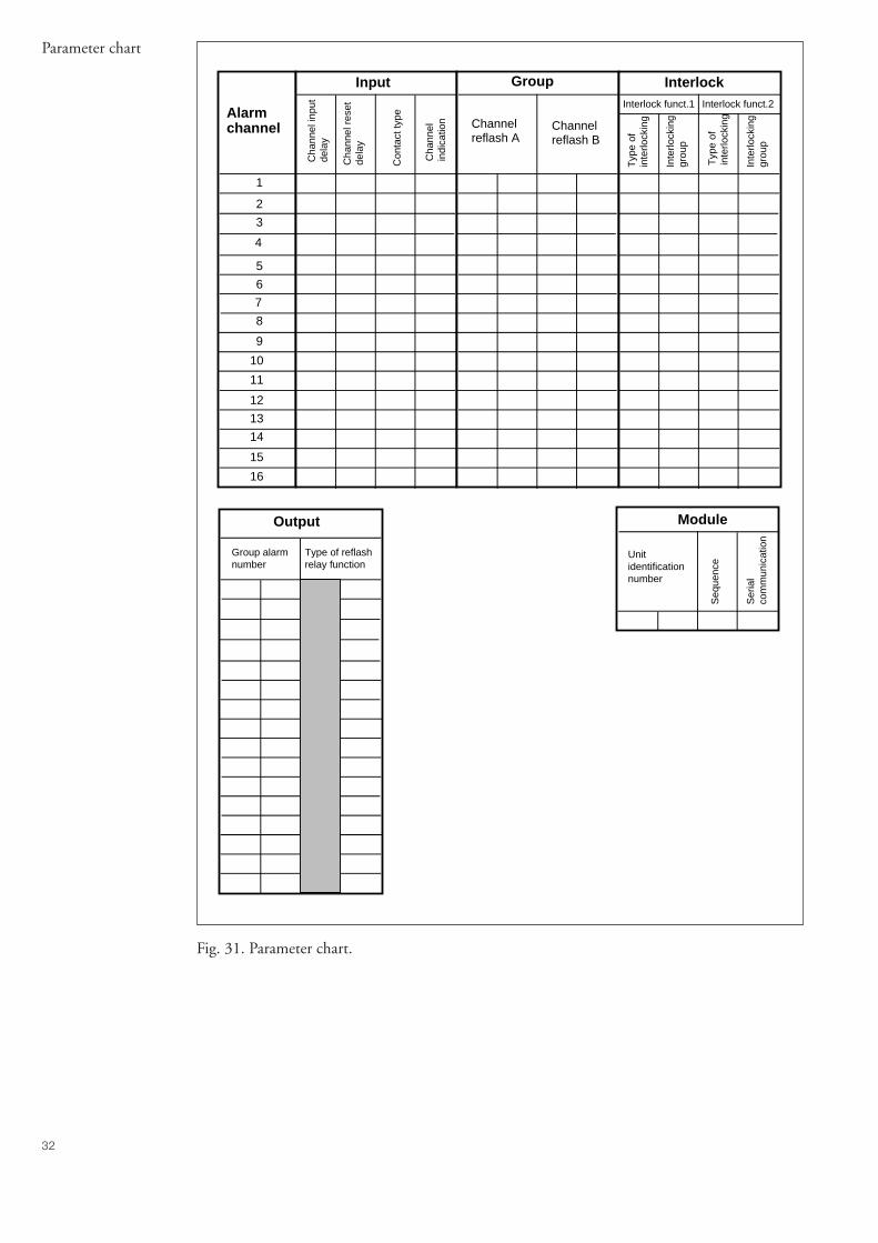
Parameter chart
Alarmchannel
1
2
3
4
5
6
7
8
9
10
11
12
13
14
15
16
Input
Cha
nnel
inpu
tde
lay
Cha
nnel
res
etde
lay
Con
tact
type
Cha
nnel
in
dica
tion
Group Interlock
Typ
e of
in
terlo
ckin
g
Inte
rlock
ing
grou
p
Channel reflash A
Channel reflash B
Typ
e of
in
terlo
ckin
g
Inte
rlock
ing
grou
p
Interlock funct.1 Interlock funct.2
Output
Group alarmnumber
Type of reflashrelay function
Module
Unit identification number
Seq
uenc
e
Ser
ial
com
mun
icat
ion
Fig. 31. Parameter chart.
33
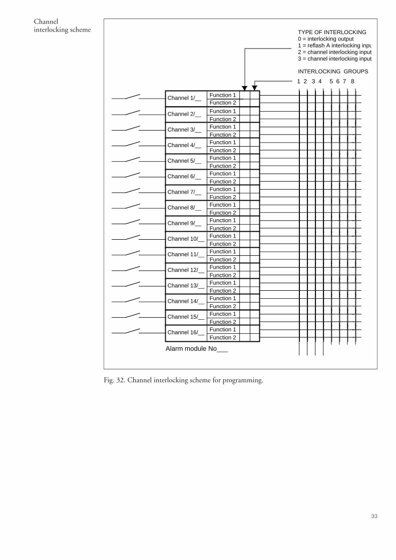
Channelinterlocking scheme
INTERLOCKING GROUPS
1 2 3 4 5 6 7 8
Channel 1/__ Function 1Function 2
Channel 2/__ Function 1Function 2
Channel 3/__ Function 1Function 2
Channel 4/__ Function 1Function 2
Channel 5/__ Function 1Function 2
Channel 6/__ Function 1Function 2
Channel 7/__ Function 1Function 2
Channel 8/__ Function 1Function 2
Channel 9/__ Function 1Function 2
Channel 10/__ Function 1Function 2
Channel 11/__ Function 1Function 2
Channel 12/__ Function 1Function 2
Channel 13/__ Function 1Function 2
Channel 14/__ Function 1Function 2
Channel 15/__ Function 1Function 2
Channel 16/__ Function 1Function 2
TYPE OF INTERLOCKING0 = interlocking output1 = reflash A interlocking inpu2 = channel interlocking input3 = channel interlocking input
Alarm module No___
Fig. 32. Channel interlocking scheme for programming.
34
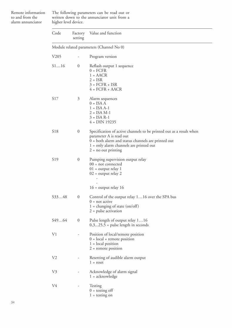
Remote informationto and from thealarm annunciator
The following parameters can be read out orwritten down to the annunciator unit from ahigher level device.
Code Factory Value and functionsetting
Module related parameters (Channel No 0)
V205 - Program version
S1…16 0 Reflash output 1 sequence0 = FCFR1 = AACR2 = ISR3 = FCFR + ISR4 = FCFR + AACR
S17 3 Alarm sequences0 = ISA A1 = ISA A-12 = ISA M-13 = ISA R-14 = DIN 19235
S18 0 Specification of active channels to be printed out as a result whenparameter A is read out0 = both alarm and status channels are printed out1 = only alarm channels are printed out2 = no out printing
S19 0 Pumping supervision output relay00 = not connected01 = output relay 102 = output relay 2
--
16 = output relay 16
S33…48 0 Control of the output relay 1…16 over the SPA bus0 = not active1 = changing of state (on/off )2 = pulse activation
S49…64 0 Pulse length of output relay 1…160,3...25,5 = pulse length in seconds
V1 - Position of local/remote position0 = local + remote position1 = local position2 = remote position
V2 - Resetting of audible alarm output1 = reset
V3 - Acknowledge of alarm signal1 = acknowledge
V4 - Testing0 = testing off1 = testing on
35
Code Factory Value and functionsetting
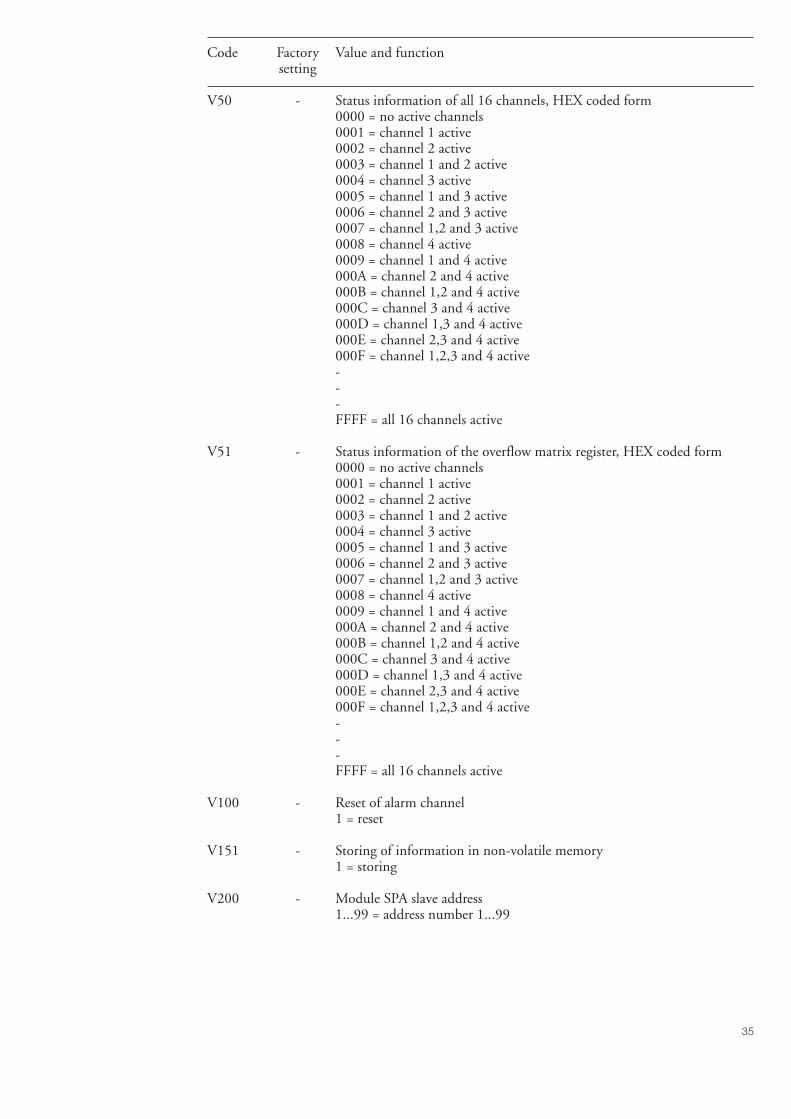
V50 - Status information of all 16 channels, HEX coded form0000 = no active channels0001 = channel 1 active0002 = channel 2 active0003 = channel 1 and 2 active0004 = channel 3 active0005 = channel 1 and 3 active0006 = channel 2 and 3 active0007 = channel 1,2 and 3 active0008 = channel 4 active0009 = channel 1 and 4 active000A = channel 2 and 4 active000B = channel 1,2 and 4 active000C = channel 3 and 4 active000D = channel 1,3 and 4 active000E = channel 2,3 and 4 active000F = channel 1,2,3 and 4 active---FFFF = all 16 channels active
V51 - Status information of the overflow matrix register, HEX coded form0000 = no active channels0001 = channel 1 active0002 = channel 2 active0003 = channel 1 and 2 active0004 = channel 3 active0005 = channel 1 and 3 active0006 = channel 2 and 3 active0007 = channel 1,2 and 3 active0008 = channel 4 active0009 = channel 1 and 4 active000A = channel 2 and 4 active000B = channel 1,2 and 4 active000C = channel 3 and 4 active000D = channel 1,3 and 4 active000E = channel 2,3 and 4 active000F = channel 1,2,3 and 4 active---FFFF = all 16 channels active
V100 - Reset of alarm channel1 = reset
V151 - Storing of information in non-volatile memory1 = storing
V200 - Module SPA slave address1...99 = address number 1...99
36
Code Factory Value and functionsetting
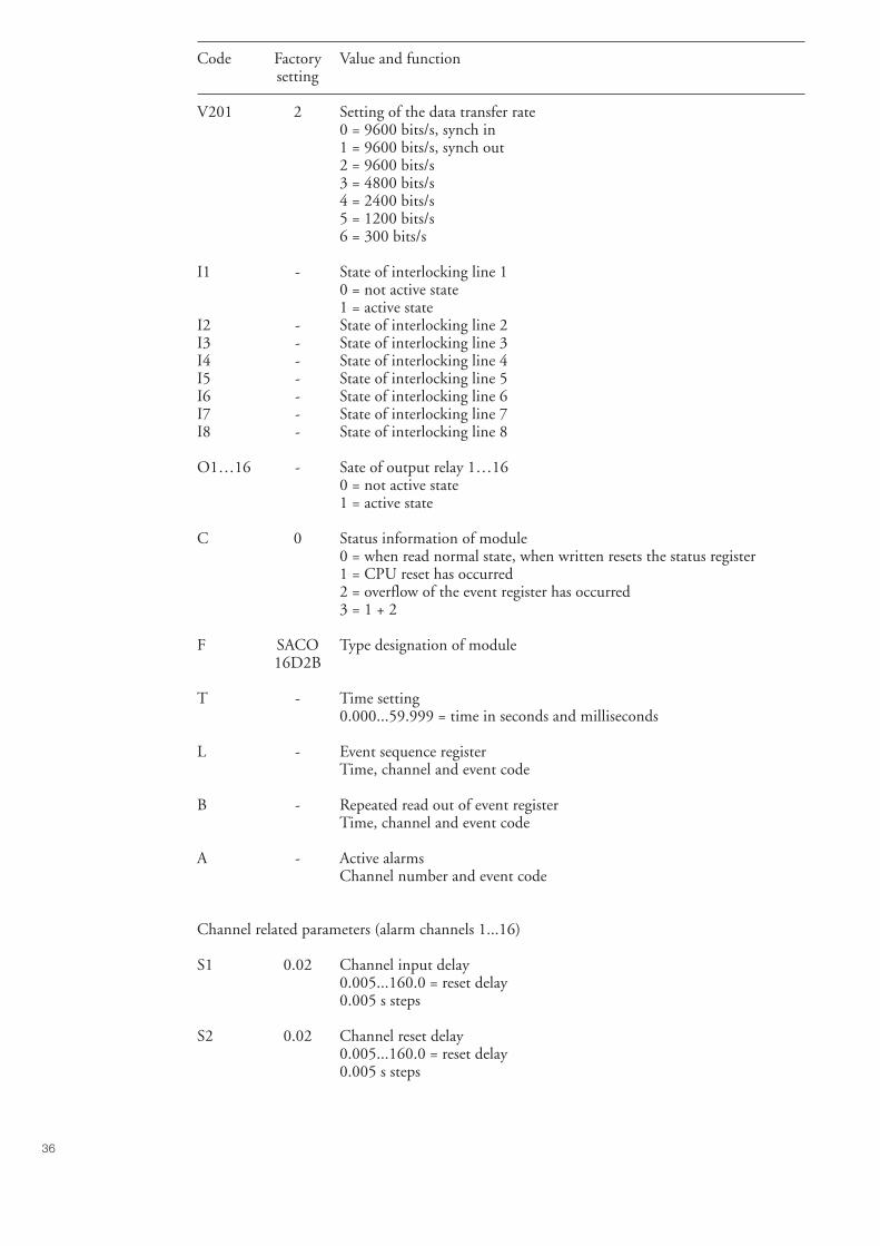
V201 2 Setting of the data transfer rate0 = 9600 bits/s, synch in1 = 9600 bits/s, synch out2 = 9600 bits/s3 = 4800 bits/s4 = 2400 bits/s5 = 1200 bits/s6 = 300 bits/s
I1 - State of interlocking line 10 = not active state1 = active state
I2 - State of interlocking line 2I3 - State of interlocking line 3I4 - State of interlocking line 4I5 - State of interlocking line 5I6 - State of interlocking line 6I7 - State of interlocking line 7I8 - State of interlocking line 8
O1…16 - Sate of output relay 1…160 = not active state1 = active state
C 0 Status information of module0 = when read normal state, when written resets the status register1 = CPU reset has occurred2 = overflow of the event register has occurred3 = 1 + 2
F SACO Type designation of module16D2B
T - Time setting0.000...59.999 = time in seconds and milliseconds
L - Event sequence registerTime, channel and event code
B - Repeated read out of event registerTime, channel and event code
A - Active alarmsChannel number and event code
Channel related parameters (alarm channels 1...16)
S1 0.02 Channel input delay0.005...160.0 = reset delay0.005 s steps
S2 0.02 Channel reset delay0.005...160.0 = reset delay0.005 s steps
37
Code Factory Value and functionsetting
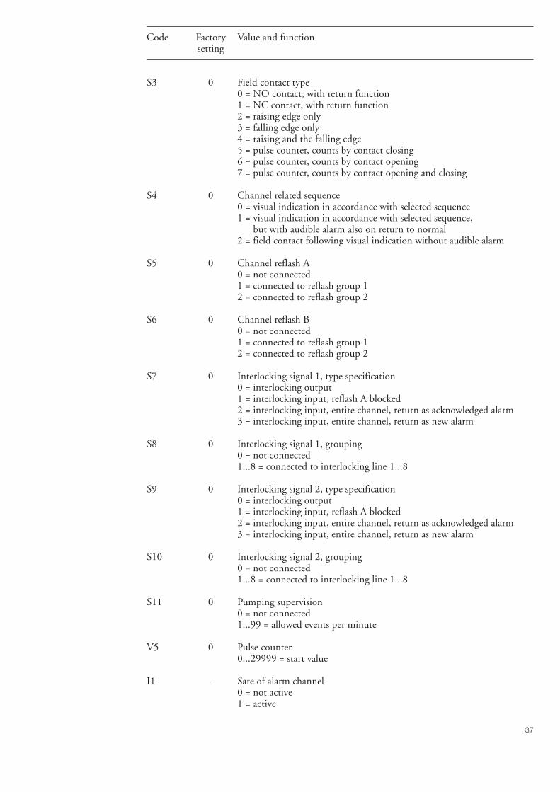
S3 0 Field contact type0 = NO contact, with return function1 = NC contact, with return function2 = raising edge only3 = falling edge only4 = raising and the falling edge5 = pulse counter, counts by contact closing6 = pulse counter, counts by contact opening7 = pulse counter, counts by contact opening and closing
S4 0 Channel related sequence0 = visual indication in accordance with selected sequence1 = visual indication in accordance with selected sequence, but with audible alarm also on return to normal2 = field contact following visual indication without audible alarm
S5 0 Channel reflash A0 = not connected1 = connected to reflash group 12 = connected to reflash group 2
S6 0 Channel reflash B0 = not connected1 = connected to reflash group 12 = connected to reflash group 2
S7 0 Interlocking signal 1, type specification0 = interlocking output1 = interlocking input, reflash A blocked2 = interlocking input, entire channel, return as acknowledged alarm3 = interlocking input, entire channel, return as new alarm
S8 0 Interlocking signal 1, grouping0 = not connected1...8 = connected to interlocking line 1...8
S9 0 Interlocking signal 2, type specification0 = interlocking output1 = interlocking input, reflash A blocked2 = interlocking input, entire channel, return as acknowledged alarm3 = interlocking input, entire channel, return as new alarm
S10 0 Interlocking signal 2, grouping0 = not connected1...8 = connected to interlocking line 1...8
S11 0 Pumping supervision0 = not connected1...99 = allowed events per minute
V5 0 Pulse counter0...29999 = start value
I1 - Sate of alarm channel0 = not active1 = active
38
Event codesCode Meaning
Module related event codes
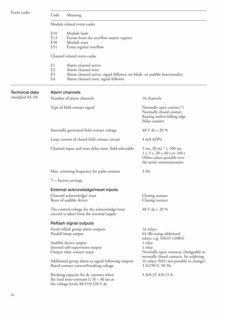
E10 Module faultE13 Events from the overflow matrix registerE50 Module resetE51 Event register overflow
Channel related event codes
E1 Alarm channel activeE2 Alarm channel resetE3 Alarm channel active, signal follower, no blink- or audible functionalityE4 Alarm channel reset, signal follower
Technical data(modified 03-10)
Alarm channelsNumber of alarm channels 16 channels
Type of field contact signal Normally open contact *)Normally closed contactRaising and/or falling edgePulse counter
Internally generated field contact voltage 48 V dc + 20 %
Loop current of closed field contact circuit 4 mA ±20%
Channel input and reset delay time, field-selectable 5 ms, 20 ms * ), 100 ms,1 s, 5 s, 20 s, 60 s or 160 sOther values possible overthe serial communication
Max. counting frequency for pulse counter 3 Hz
*) = factory settings
External acknowledge/reset inputsChannel acknowledge/ reset Closing contactReset of audible device Closing contact
The control voltage for the acknowledge/reset 48 V dc + 20 %circuits is taken from the internal supply
Reflash signal outputsFixed reflash group alarm outputs 14 relaysParalell lamp output 64 (By using additional
relays, e.g. SACO 128R4)Audible device output 1 relayInternal self-supervision output 1 relayOutput relay contact types Normally open contacts, changeable to
normally closed contacts by solderingAdditional group alarm or signal following outputs 16 relays (NO, not possible to change)Rated contact current/breaking voltage 3 A/250 V, 50 Hz
Breaking capacity for dc currents when 3 A/0.25 A/0.15 Athe load time-constant L/ R < 40 ms atthe voltage levels 48/110/220 V dc
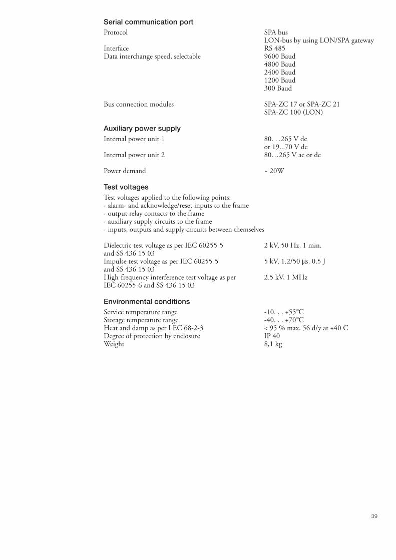
39
Serial communication portProtocol SPA bus
LON-bus by using LON/SPA gatewayInterface RS 485Data interchange speed, selectable 9600 Baud
4800 Baud2400 Baud1200 Baud300 Baud
Bus connection modules SPA-ZC 17 or SPA-ZC 21SPA-ZC 100 (LON)
Auxiliary power supplyInternal power unit 1 80. . .265 V dc
or 19...70 V dcInternal power unit 2 80…265 V ac or dc
Power demand ~ 20W
Test voltagesTest voltages applied to the following points:- alarm- and acknowledge/reset inputs to the frame- output relay contacts to the frame- auxiliary supply circuits to the frame- inputs, outputs and supply circuits between themselves
Dielectric test voltage as per IEC 60255-5 2 kV, 50 Hz, 1 min.and SS 436 15 03Impulse test voltage as per IEC 60255-5 5 kV, 1.2/50 µs, 0.5 Jand SS 436 15 03High-frequency interference test voltage as per 2.5 kV, 1 MHzIEC 60255-6 and SS 436 15 03
Environmental conditionsService temperature range -10. . . +55°CStorage temperature range -40. . . +70°CHeat and damp as per I EC 68-2-3 < 95 % max. 56 d/y at +40 CDegree of protection by enclosure IP 40Weight 8,1 kg
40
Testing The alarm annunciator unit is provided withan automatic self-supervision system whichmonitors the internal system voltages as well asthe function of the microprocessor and the logi-cal circuits.
If an internal fault situation is detected, the con-tact of the output relay of the self-supervisionsystem drops off and the FAULT LED isswitched on.
The LED indicators can be tested by pressingthe test push-button on the module SWDM3A1, located to the left in the rack (if present),continuously for more than one second. Thenall LED indicators, except the FAULT indica-tor, on the front panel are switched on. If thepush-button is depressed for more than 15 sec-onds, the FAULT indicator also turns on andthe output relay of the self supervision systemdrops off.
It is recommended that the function of the fieldcontact circuits are tested by performing pri-mary tests to the field contacts.
Maintenanceand repair
When the annunciator unit is operating undernormal service conditions as specified in thesection "Technical data", the annunciator unitis practically maintenance free. The modules in-clude no parts or components, which are sub-ject to an abnormal physical or electrical wearunder normal operating conditions.
If the environmental conditions at the operat-ing site differ from those specified, as to ambi-ent temperature, humidity or if the atmospherearound the annunciator unit holds chemicallyactive gases or dust, the modules ought to bevisually inspected in association with the sec-ondary testing being performed or whenever theplug-in modules are withdrawn from the case.At the visual inspection the following thingsshould be noted:- possible mechanical damage of the mounting
case, mounting brackets or frame, plastic lidor its rubber gasket, plug-in units or their con-nection sockets
- signs of oxidation on the PCBs, componentlegs and cups, screws and other metallic parts
- traces of dust and dirt accumulating inside theplastic lid, on the PCB or inside the case.Check the condition of the rubber gasket ofthe lid.
If the annunciator unit fails in operation or ifthe operating values differ from those specified,the annunciator unit should be checked andrepaired by a competent specialist in an author-ized repair shop.
Generally a fault can be eliminated by chang-ing a plug-in module, please refer to the sparepart list. When a new alarm module SWPM3A1B is inserted, the programmed parametermemory of the old alarm module can be pluggedto the new module. Thus the new alarm mod-ule is ready to work with the same operatingvalues as the old one without being separatelyprogrammed. The parameter memory is markedD17.
IMPORTANT!When the memory circuit is plugged in, the sloton the circuit should point towards the frontpanel of the module. In this way possible dam-age of the memory circuit can be avoided. Pleasealways use EDS protection when handling theelectronic circuit
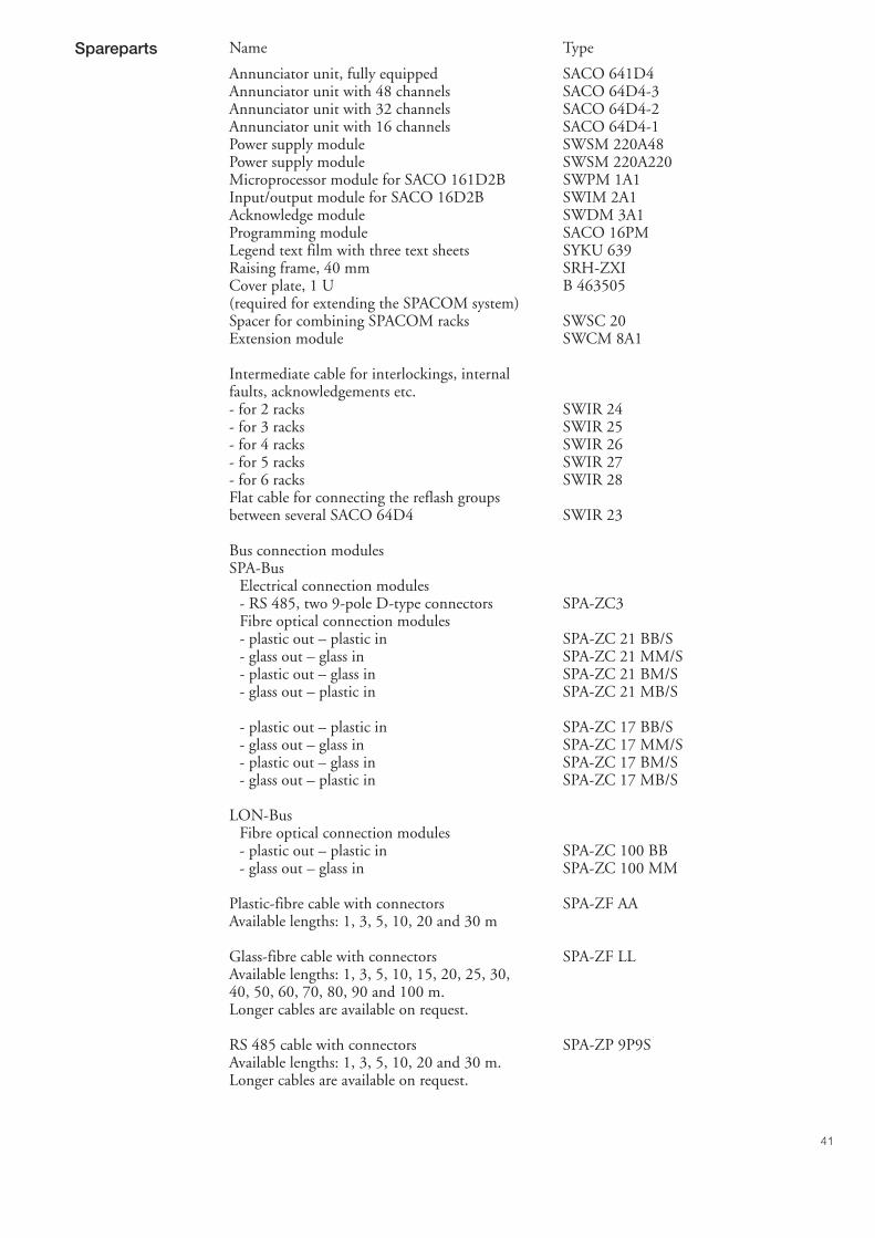
41
Spareparts Name Type
Annunciator unit, fully equipped SACO 641D4Annunciator unit with 48 channels SACO 64D4-3Annunciator unit with 32 channels SACO 64D4-2Annunciator unit with 16 channels SACO 64D4-1Power supply module SWSM 220A48Power supply module SWSM 220A220Microprocessor module for SACO 161D2B SWPM 1A1Input/output module for SACO 16D2B SWIM 2A1Acknowledge module SWDM 3A1Programming module SACO 16PMLegend text film with three text sheets SYKU 639Raising frame, 40 mm SRH-ZXICover plate, 1 U B 463505(required for extending the SPACOM system)Spacer for combining SPACOM racks SWSC 20Extension module SWCM 8A1
Intermediate cable for interlockings, internalfaults, acknowledgements etc.- for 2 racks SWIR 24- for 3 racks SWIR 25- for 4 racks SWIR 26- for 5 racks SWIR 27- for 6 racks SWIR 28Flat cable for connecting the reflash groupsbetween several SACO 64D4 SWIR 23
Bus connection modulesSPA-Bus
Electrical connection modules- RS 485, two 9-pole D-type connectors SPA-ZC3Fibre optical connection modules- plastic out – plastic in SPA-ZC 21 BB/S- glass out – glass in SPA-ZC 21 MM/S- plastic out – glass in SPA-ZC 21 BM/S- glass out – plastic in SPA-ZC 21 MB/S
- plastic out – plastic in SPA-ZC 17 BB/S- glass out – glass in SPA-ZC 17 MM/S- plastic out – glass in SPA-ZC 17 BM/S- glass out – plastic in SPA-ZC 17 MB/S
LON-BusFibre optical connection modules- plastic out – plastic in SPA-ZC 100 BB- glass out – glass in SPA-ZC 100 MM
Plastic-fibre cable with connectors SPA-ZF AAAvailable lengths: 1, 3, 5, 10, 20 and 30 m
Glass-fibre cable with connectors SPA-ZF LLAvailable lengths: 1, 3, 5, 10, 15, 20, 25, 30,40, 50, 60, 70, 80, 90 and 100 m.Longer cables are available on request.
RS 485 cable with connectors SPA-ZP 9P9SAvailable lengths: 1, 3, 5, 10, 20 and 30 m.Longer cables are available on request.
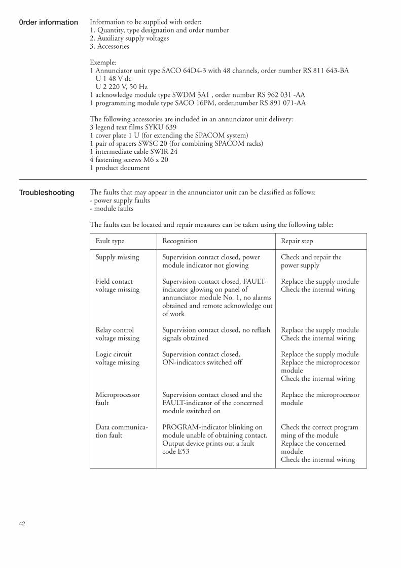
42
0rder information Information to be supplied with order:1. Quantity, type designation and order number2. Auxiliary supply voltages3. Accessories
Exemple:1 Annunciator unit type SACO 64D4-3 with 48 channels, order number RS 811 643-BA
U 1 48 V dcU 2 220 V, 50 Hz
1 acknowledge module type SWDM 3A1 , order number RS 962 031 -AA1 programming module type SACO 16PM, order,number RS 891 071-AA
The following accessories are included in an annunciator unit delivery:3 legend text films SYKU 6391 cover plate 1 U (for extending the SPACOM system)1 pair of spacers SWSC 20 (for combining SPACOM racks)1 intermediate cable SWIR 244 fastening screws M6 x 201 product document
Troubleshooting The faults that may appear in the annunciator unit can be classified as follows:- power supply faults- module faults
The faults can be located and repair measures can be taken using the following table:
Fault type Recognition Repair step
Supply missing Supervision contact closed, power Check and repair themodule indicator not glowing power supply
Field contact Supervision contact closed, FAULT- Replace the supply modulevoltage missing indicator glowing on panel of Check the internal wiring
annunciator module No. 1, no alarmsobtained and remote acknowledge outof work
Relay control Supervision contact closed, no reflash Replace the supply modulevoltage missing signals obtained Check the internal wiring
Logic circuit Supervision contact closed, Replace the supply modulevoltage missing ON-indicators switched off Replace the microprocessor
moduleCheck the internal wiring
Microprocessor Supervision contact closed and the Replace the microprocessorfault FAULT-indicator of the concerned module
module switched on
Data communica- PROGRAM-indicator blinking on Check the correct programtion fault module unable of obtaining contact. ming of the module
Output device prints out a fault Replace the concernedcode E53 module
Check the internal wiring

43
Fault type Recognition Repair step
Fault on input No alarm from a particular channel Check the interlockingor output circuit A certain output signal is missing settings
A certain remote acknowledge Check the external wiringfunction out of work Replace the concerned
input/output moduleReplace the concernedannunciator moduleCheck the internal wiring
When replacing a microprocessor module, theprogrammed parameters can be moved to thenew module by moving the parameter memorycircuits from the old PC-boards to the newmodule. The parameters of the SWPM 1A1Bmodule are stored in the circuit D7.
IMPORTANT!The memory circuits have to be inserted in theirsockets so that the slot of the casing faces thefront side of the module. This will prevent thememory circuits from being damaged.

1MR
S 7
5201
4-M
UM
E
N
ABB OyDistribution AutomationP.O.Box 699FI-65101 VaasaFINLANDTel. +358 (0)10 22 11Fax.+358 (0)10 22 41094www.abb.com/substationautomation
Top Related