


Languages
Pages
Legal


Technical catalogue - Preliminary
SACE FORMULA New low voltage moulded-case circuit-breakers up to 630A


Main characteristics 1
Circuit-breakers for power distribution 2
Accessories 3
Characteristic curves and technical information 4
Wiring diagrams 5
Overall dimensions 6
Glossary 7
1SDC210032D0204
Formula_00_indice+avanticat.indd 1 21/02/2011 9.36.25

2
SACE FORMULA. Simplicity and Quality in a Single Product.
SACE FORMULA is the expression of all ABB SACE’s long experience of several decades in all its effectiveness: SACE FORMULA was born basic, but is able to amaze with its extreme versatility of use.The main strong points of the new moulded-case circuit-breakers are:- just a few but essential versions of the circuit-breakers, easy to select and order;- availability of circuit-breakers of all polarities, dedicated to the various applications;- possibility of using the accessories most often requested;- circuit-breaker depths further reduced; - a new installation system making assembly of the circuit-breakers easier;- suitable for use at 50°C without derating.
Formula_00_indice+avanticat.indd 2 21/02/2011 9.36.29

3
The new SACE FORMULA family consists of three new A1, A2 and A3 frames which reach up to 125A, 250A and 630A respectively. The three frames are available in the fixed version, with front terminals. The protection trip unit has fixed thermal and magnetic threshold values for putting the circuit-breaker into service more rapidly. This way selection becomes simple and precise. With a few sales codes which simplify selection and make ordering easier. Installation is simplified, and thanks to easy and rapid fixing operations and set-up, the circuit-breaker is ready for use immediately.
Formula_00_indice+avanticat.indd 3 21/02/2011 9.36.35
4
SACE FORMULA. The Easy and Precise Choice.
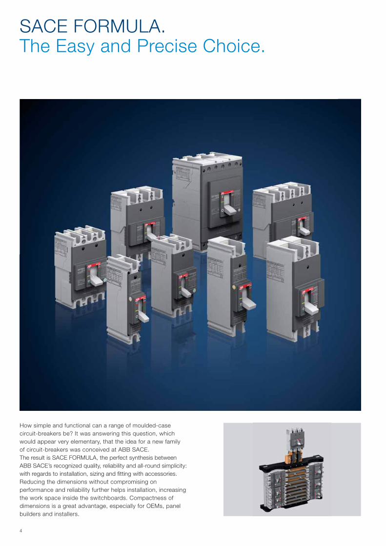
How simple and functional can a range of moulded-case circuit-breakers be? It was answering this question, which would appear very elementary, that the idea for a new family of circuit-breakers was conceived at ABB SACE. The result is SACE FORMULA, the perfect synthesis between ABB SACE’s recognized quality, reliability and all-round simplicity: with regards to installation, sizing and fitting with accessories. Reducing the dimensions without compromising on performance and reliability further helps installation, increasing the work space inside the switchboards. Compactness of dimensions is a great advantage, especially for OEMs, panel builders and installers.
Formula_00_indice+avanticat.indd 4 21/02/2011 9.36.46
5
SACE FORMULA. Winners in All Applications.
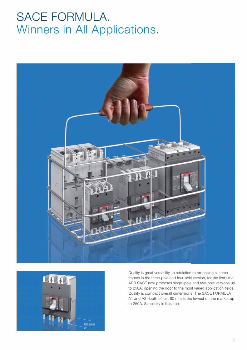
Quality is great versatility. In addiction to proposing all three frames in the three-pole and four-pole version, for the first time ABB SACE now proposes single-pole and two-pole versions up to 250A, opening the door to the most varied application fields.Quality is compact overall dimensions. The SACE FORMULA A1 and A2 depth of just 60 mm is the lowest on the market up to 250A. Simplicity is this, too.
Formula_00_indice+avanticat.indd 5 21/02/2011 9.36.52

1/11SDC210032D0204
Main characteristics
Content
General information ............................................................................................................. 1/2
Regulations and reference Standards ................................................................................ 1/3
Identification of the SACE FORMULA circuit-breakers ..................................................... 1/4
Formula_01_caratteristiche.indd 1 21/02/2011 9.37.31

1/2
B
A
B
1SD
C21
0610
F000
11S
DC
2106
11F0
001
1SD
C21
0612
F000
11S
DC
2106
13F0
001
1SD
C21
0612
F000
1
1SDC210032D0204
Construction characteristics General information
The references in round brackets (Gx.x) in the technical catalogue refer to the Glossary in the final charter of the technical catalogue.
All the moulded-case circuit-breakers in the SACE FORMULA family are constructed in ac-cordance with the following construction characteristics: • double insulation(G1.4);• positive operation(G1.5);• isolation behaviour(G1.6);• electromagnetic compatibility(G1.7);• tropicalization(G1.8);• power supply from the top towards the bottom or vice versa;• versatility of the installation. It is possible to mount the circuit-breaker either in the horizontal,
vertical, or lying down position without undergoing any derating of the rated characteristics;• no nominal performance derating for use up to an altitude of 2000m. Above 2000m, the
properties of the atmosphere (composition of the air, dielectric strength, cooling power and pressure) change, having an impact on the main parameters which define the circuit-breaker. The table below gives the changes to the main performance parameters;
• SACE FORMULA circuit-breakers can be used in ambient with a temperature between -25°C +70°C and stored in a room with atmospheric temperature between -40°C +70°C. SACE FORMULA circuit-breakers listed below are designed to hold 100% In at 50°C without tripping in normal condition:
- SACE A1 and A2, up to 250A (except A1 125); - SACE A3 300-400A special version 50°C. For detailed temperature performances of all SACE FORMULA breakers, please refer to
paragraph “Temperature performances” in the Characteristic Curves and Technical Informa-tion Chapter;
• different protection degrees IP (International Protection) (G1.2);
Altitude 2000m 3000m 4000m 5000m
A1 A2-A3 A1 A2-A3 A1 A2-A3 A1 A2-A3
Rated service voltage, Ue [V] 500 550 440 484 390 429 340 374
Rated uninterrupted current % 100 100 98 98 95 95 90 90
• circuit-breaker weights;
Circuit-breaker with front
Circuit-breaker without front (1)
Circuit-breaker with RHE RHD
Circuit-breaker with HTC
Circuit-breaker with LTC
Circuit-breaker with FLD
A IP 40 IP 20 IP 40 IP 40 IP 40 IP 40
B IP 20 IP 20 IP 20 IP 40 IP 30 IP 20
(1) During installation of the electrical accessories
Weights A1 [Kg] A2 [Kg] A3 [Kg]
Circuit-breaker 1 pole 0.245 0.37 -
Circuit-breaker 2 poles 0.47 0.73 -
Circuit-breaker 3 poles 0.7 1.1 3.25
Circuit-breaker 4 poles 0.925 1.145 4.15
Installation positions
Double insulation
Positive operation
Protection degrees
Test pushbotton
• all the SACE FORMULA circuit-breakers are fitted with a Test pushbutton which allows the release test to be done. This test must be carried out with the circuit-breaker closed.
Formula_01_caratteristiche.indd 2 21/02/2011 9.37.34
1/31SDC210032D0204
Conformity with StandardsThe SACE FORMULA circuit-breakers and their accessories are constructed in conformity with:• Standards (G.4.1): – IEC 60947-2;• Directives(G.4.2): – EC directive: “Low Voltage Directives” (LVD) no. 2006/95/CE (in replacement of 73/23/
CEE and subsequent amendments); – EC directive: “Electromagnetic Compatibility Directive” (EMC) no. 89/336 EEC.
Certification of conformity with the product Standards is carried out in the ABB SACE test room (accredited by SINAL - certificate No. 062/1997-) in respect of the EN 45011 European Standard, by the Italian certification body ACAE (Association for Certification of Electrical Ap-paratus), member of the European LOVAG organisation (Low Voltage Agreement Group) and by the Swedish certification body SEMKO belonging to the international IECEE organisation.
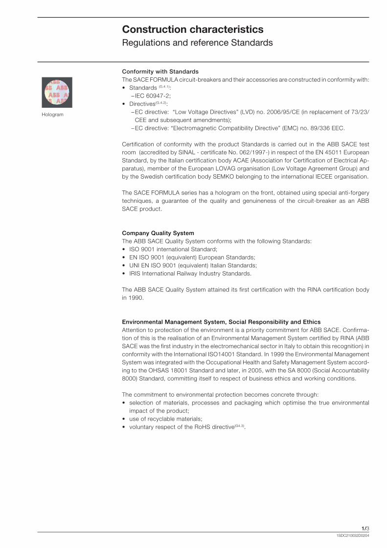
The SACE FORMULA series has a hologram on the front, obtained using special anti-forgery techniques, a guarantee of the quality and genuineness of the circuit-breaker as an ABB SACE product.
Company Quality SystemThe ABB SACE Quality System conforms with the following Standards:• ISO 9001 international Standard;• EN ISO 9001 (equivalent) European Standards;• UNI EN ISO 9001 (equivalent) Italian Standards;• IRIS International Railway Industry Standards.
The ABB SACE Quality System attained its first certification with the RINA certification body in 1990.
Environmental Management System, Social Responsibility and EthicsAttention to protection of the environment is a priority commitment for ABB SACE. Confirma-tion of this is the realisation of an Environmental Management System certified by RINA (ABB SACE was the first industry in the electromechanical sector in Italy to obtain this recognition) in conformity with the International ISO14001 Standard. In 1999 the Environmental Management System was integrated with the Occupational Health and Safety Management System accord-ing to the OHSAS 18001 Standard and later, in 2005, with the SA 8000 (Social Accountability 8000) Standard, committing itself to respect of business ethics and working conditions.
The commitment to environmental protection becomes concrete through:• selection of materials, processes and packaging which optimise the true environmental
impact of the product;• use of recyclable materials; • voluntary respect of the RoHS directive(G4.3).
Hologram
Construction characteristics Regulations and reference Standards
Formula_01_caratteristiche.indd 3 21/02/2011 9.37.35

1/4
In=100A
7
3
4
135
67
11
122814
10
9
1
7
4
513
10
3
14
9
1
6
1SD
C21
0614
F000
1
1SD
C21
0615
F000
1
15
1SDC210032D0204
Construction characteristics Identification of the SACE FORMULA circuit-breakers
The characteristics of the circuit-breakers are given on the label on the front of the circuit-breaker, and on the side label.
1. Name of the circuit-breaker and performance level;
2. In: rated uninterrupted current*;3. Uimp: rated impulse withstand
voltage*;4. Ui: insulation voltage*;5. Ics: rated short-circuit service
breaking capacity*;6. Icu: rated ultimate short-circuit
breaking capacity*; 7. Ue: rated service voltage*;8. Symbol of isolation behaviour*;9. Reference Standard IEC 60947-2*;10. Serial number;11. Anti-forgery;12. Test pushbutton;13. Category of use;14. CE Marking;15. Utilization at 50°C (except for A1
125A).
* in compliance with the IEC 60947-2 Standard
Front label
Side label
��������� ���������������� �����
Formula_01_caratteristiche.indd 4 21/02/2011 9.37.35
2/11SDC210032D0204
Circuit-breakers for power distribution
Content
General characteristics ..................................................................................................... 2/2
Thermomagnetic trip units ............................................................................................... 2/4
Ordering codes ................................................................................................................ 2/5
Electronic trip units ............................................................................................................ 2/9
Ordering codes ................................................................................................................ 2/9
Formula_02_gamma.indd 1 21/02/2011 9.38.07
2/2
SACE FORMULA A1
SACE FORMULA A2
SACE FORMULA A3
1SDC210032D0204
Circuit-breakers for power distributionGeneral characteristics
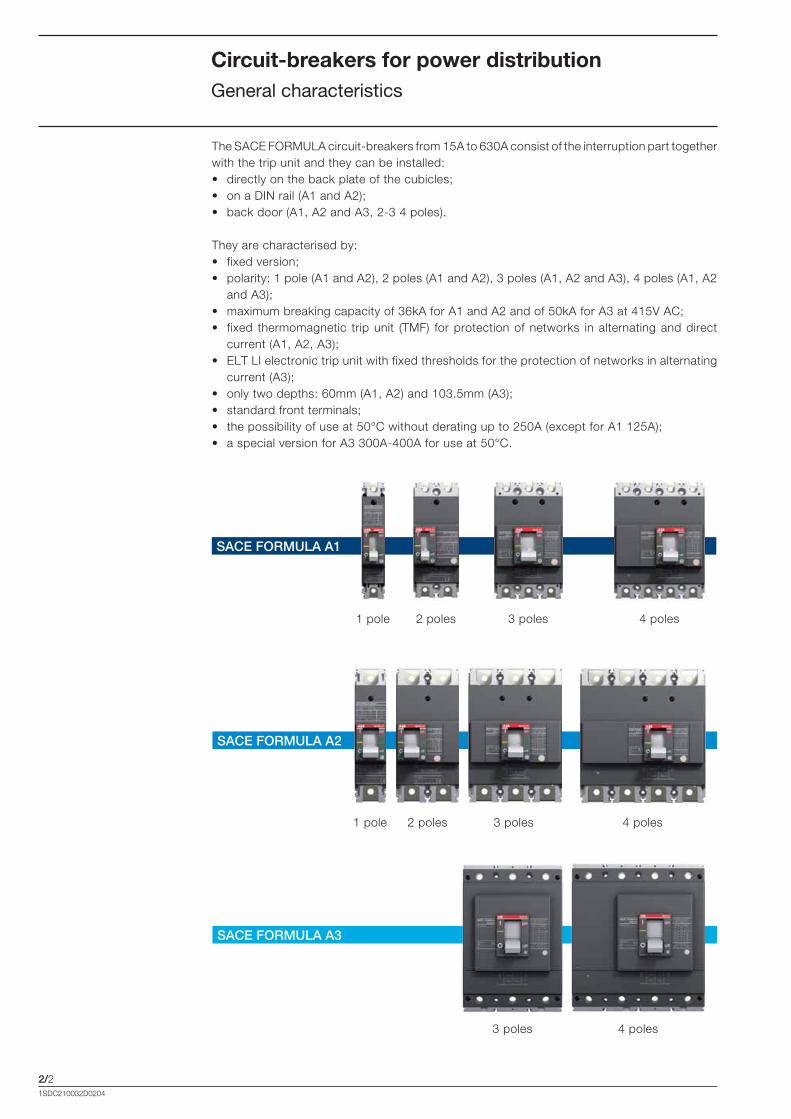
The SACE FORMULA circuit-breakers from 15A to 630A consist of the interruption part together with the trip unit and they can be installed:• directly on the back plate of the cubicles;• on a DIN rail (A1 and A2);• back door (A1, A2 and A3, 2-3 4 poles).
They are characterised by: • fixed version; • polarity: 1 pole (A1 and A2), 2 poles (A1 and A2), 3 poles (A1, A2 and A3), 4 poles (A1, A2
and A3);• maximum breaking capacity of 36kA for A1 and A2 and of 50kA for A3 at 415V AC;• fixed thermomagnetic trip unit (TMF) for protection of networks in alternating and direct
current (A1, A2, A3);• ELT LI electronic trip unit with fixed thresholds for the protection of networks in alternating
current (A3); • only two depths: 60mm (A1, A2) and 103.5mm (A3); • standard front terminals;• the possibility of use at 50°C without derating up to 250A (except for A1 125A); • a special version for A3 300A-400A for use at 50°C.
4 poles1 pole 2 poles 3 poles
4 poles1 pole 2 poles 3 poles
4 poles3 poles
Formula_02_gamma.indd 2 21/02/2011 9.38.13
2/3
W D
H
1SDC210032D0204
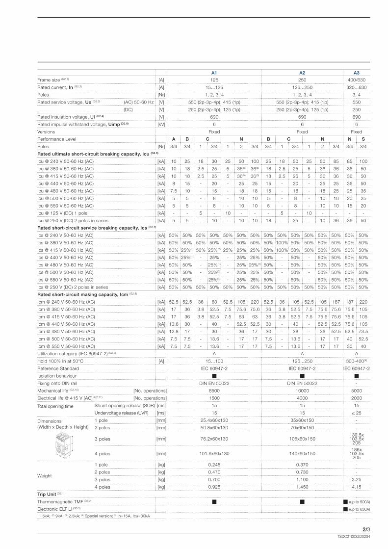
A1 A2 A3
Frame size (G2.1) [A] 125 250 400/630
Rated current, In (G2.2) [A] 15...125 125...250 320...630
Poles [Nr] 1, 2, 3, 4 1, 2, 3, 4 3, 4
Rated service voltage, Ue (G2.3) (AC) 50-60 Hz [V] 550 (2p-3p-4p); 415 (1p) 550 (2p-3p-4p); 415 (1p) 550
(DC) [V] 250 (2p-3p-4p); 125 (1p) 250 (2p-3p-4p); 125 (1p) 250
Rated insulation voltage, Ui (G2.4) [V] 690 690 690
Rated impulse withstand voltage, Uimp (G2.5) [kV] 6 6 6
Versions Fixed Fixed Fixed
Performance Level A B C N B C N N S
Poles [Nr] 3/4 3/4 1 3/4 1 2 3/4 3/4 1 3/4 1 2 3/4 3/4 3/4
Rated ultimate short-circuit breaking capacity, Icu (G2.6)
Icu @ 240 V 50-60 Hz (AC) [kA] 10 25 18 30 25 50 100 25 18 50 25 50 85 85 100
Icu @ 380 V 50-60 Hz (AC) [kA] 10 18 2.5 25 5 36(5) 36(5) 18 2.5 25 5 36 36 36 50
Icu @ 415 V 50-60 Hz (AC) [kA] 10 18 2.5 25 5 36(5) 36(5) 18 2.5 25 5 36 36 36 50
Icu @ 440 V 50-60 Hz (AC) [kA] 8 15 - 20 - 25 25 15 - 20 - 25 25 36 50
Icu @ 480 V 50-60 Hz (AC) [kA] 7.5 10 - 15 - 18 18 15 - 18 - 18 25 25 35
Icu @ 500 V 50-60 Hz (AC) [kA] 5 5 - 8 - 10 10 5 - 8 - 10 10 20 25
Icu @ 550 V 50-60 Hz (AC) [kA] 5 5 - 8 - 10 10 5 - 8 - 10 10 15 20
Icu @ 125 V (DC) 1 pole [kA] - - 5 - 10 - - - 5 - 10 - - - -
Icu @ 250 V (DC) 2 poles in series [kA] 5 5 - 10 - 10 10 18 - 25 - 10 36 36 50
Rated short-circuit service breaking capacity, Ics (G2.7)
Ics @ 240 V 50-60 Hz (AC) [kA] 50% 50% 50% 50% 50% 50% 50% 50% 50% 50% 50% 50% 50% 50% 50%
Ics @ 380 V 50-60 Hz (AC) [kA] 50% 50% 50% 50% 50% 50% 50% 50% 100% 50% 50% 50% 50% 50% 50%
Ics @ 415 V 50-60 Hz (AC) [kA] 50% 25%(1) 50% 25%(2) 25% 25% 25% 50% 100% 50% 50% 50% 50% 50% 50%
Ics @ 440 V 50-60 Hz (AC) [kA] 50% 25%(1) - 25% - 25% 25% 50% - 50% - 50% 50% 50% 50%
Ics @ 480 V 50-60 Hz (AC) [kA] 50% 50% - 25%(1) - 25% 25%(1) 50% - 50% - 50% 50% 50% 50%
Ics @ 500 V 50-60 Hz (AC) [kA] 50% 50% - 25%(3) - 25% 25% 50% - 50% - 50% 50% 50% 50%
Ics @ 550 V 50-60 Hz (AC) [kA] 50% 50% - 25%(3) - 25% 25% 50% - 50% - 50% 50% 50% 50%
Ics @ 250 V (DC) 2 poles in series [kA] 50% 50% 50% 50% 50% 50% 50% 50% 50% 50% 50% 50% 50% 50% 50%
Rated short-circuit making capacity, Icm (G2.8)
Icm @ 240 V 50-60 Hz (AC) [kA] 52.5 52.5 36 63 52.5 105 220 52.5 36 105 52.5 105 187 187 220
Icm @ 380 V 50-60 Hz (AC) [kA] 17 36 3.8 52.5 7.5 75.6 75.6 36 3.8 52.5 7.5 75.6 75.6 75.6 105
Icm @ 415 V 50-60 Hz (AC) [kA] 17 36 3.8 52.5 7.5 63 63 36 3.8 52.5 7.5 75.6 75.6 75.6 105
Icm @ 440 V 50-60 Hz (AC) [kA] 13.6 30 - 40 - 52.5 52.5 30 - 40 - 52.5 52.5 75.6 105
Icm @ 480 V 50-60 Hz (AC) [kA] 12.8 17 - 30 - 36 17 30 - 36 - 36 52.5 52.5 73.5
Icm @ 500 V 50-60 Hz (AC) [kA] 7.5 7.5 - 13.6 - 17 17 7.5 - 13.6 - 17 17 40 52.5
Icm @ 550 V 50-60 Hz (AC) [kA] 7.5 7.5 - 13.6 - 17 17 7.5 - 13.6 - 17 17 30 40
Utilization category (IEC 60947-2) (G2.9) A A A
Hold 100% In at 50°C [A] 15...100 125...250 300-400(4)
Reference Standard IEC 60947-2 IEC 60947-2 IEC 60947-2
Isolation behaviour � � �
Fixing onto DIN rail DIN EN 50022 DIN EN 50022 -
Mechanical life (G2.10) [No. operations] 8500 10000 5000
Electrical life @ 415 V (AC) (G2.11) [No. operations] 1500 4000 2000
Total opening time Shunt opening release (SOR) [ms] 15 15 15
Undervoltage release (UVR) [ms] 15 15 < 25
Dimensions (Width x Depth x Height)
1 pole [mm] 25.4x60x130 35x60x150 -
2 poles [mm] 50.8x60x130 70x60x150 -
3 poles [mm] 76.2x60x130 105x60x150139.5x103.5x
205
4 poles [mm] 101.6x60x130 140x60x150 186x
103.5x205
Weight
1 pole [kg] 0.245 0.370 -
2 poles [kg] 0.470 0.730 -
3 poles [kg] 0.700 1.100 3.25
4 poles [kg] 0.925 1.450 4.15
Trip Unit (G3.1)
Thermomagnetic TMF (G3.2) � � ��(up to 500A)
Electronic ELT LI (G3.3) ��(up to 630A)
(1) 5kA; (2) 9kA; (3) 2.5kA; (4) Special version; (5) In=15A, Icu=30kA
Formula_02_gamma.indd 3 21/02/2011 9.38.15
2/4
1SD
C21
0626
F000
1
1SDC210032D0204
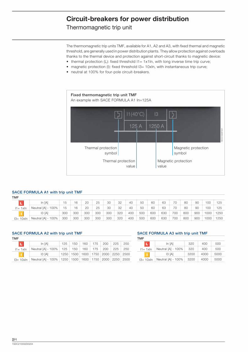
The thermomagnetic trip units TMF, available for A1, A2 and A3, with fixed thermal and magnetic threshold, are generally used in power distribution plants. They allow protection against overloads thanks to the thermal device and protection against short-circuit thanks to magnetic device: • thermal protection (L): fixed threshold I1= 1x1In, with long inverse time trip curve;• magnetic protection (I): fixed threshold I3= 10xIn, with instantaneous trip curve;• neutral at 100% for four-pole circuit-breakers.
Circuit-breakers for power distributionThermomagnetic trip unit
SACE FORMULA A1 with trip unit TMFTMF
I1= 1xIn
In [A] 15 16 20 25 30 32 40 50 60 63 70 80 90 100 125
Neutral [A] - 100% 15 16 20 25 30 32 40 50 60 63 70 80 90 100 125
I3= 10xIn
I3 [A] 300 300 300 300 300 320 400 500 600 630 700 800 900 1000 1250
Neutral [A] - 100% 300 300 300 300 300 320 400 500 600 630 700 800 900 1000 1250
SACE FORMULA A2 with trip unit TMFTMF
I1= 1xIn
In [A] 125 150 160 175 200 225 250
Neutral [A] - 100% 125 150 160 175 200 225 250
I3= 10xIn
I3 [A] 1250 1500 1600 1750 2000 2250 2500
Neutral [A] - 100% 1250 1500 1600 1750 2000 2250 2500
SACE FORMULA A3 with trip unit TMFTMF
I1= 1xIn
In [A] 320 400 500
Neutral [A] - 100% 320 400 500
I3= 10xIn
I3 [A] 3200 4000 5000
Neutral [A] - 100% 3200 4000 5000
Magnetic protection symbol
Magnetic protection value
Thermal protection value
Thermal protection symbol
Fixed thermomagnetic trip unit TMFAn example with SACE FORMULA A1 In=125A
Formula_02_gamma.indd 4 21/02/2011 9.38.16
2/5
1SD
C21
0627
F000
1
1SD
C21
0628
F000
1
1SDC210032D0204
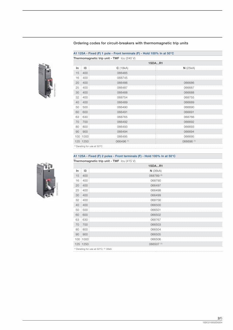
A1 125A - Fixed (F) 1 pole - Front terminals (F) - Hold 100% In at 50°C
Thermomagnetic trip unit - TMF Icu (240 V)
1SDA...R1
In I3 C (18kA) N (25kA)
15 400 066485
16 400 068745
20 400 066486 066686
25 400 066487 066687
30 400 066488 066688
32 400 068754 068755
40 400 066489 066689
50 500 066490 066690
60 600 066491 066691
63 630 068765 068766
70 700 066492 066692
80 800 066493 066693
90 900 066494 066694
100 1000 066495 066695
125 1250 066496 (1) 066696 (1)
(1) Derating for use at 50°C
A1 125A - Fixed (F) 2 poles - Front terminals (F) - Hold 100% In at 50°C
Thermomagnetic trip unit - TMF Icu (415 V)
1SDA...R1
In I3 N (36kA)
15 400 068789 (2)
16 400 068790
20 400 066497
25 400 066498
30 400 066499
32 400 068756
40 400 066500
50 500 066501
60 600 066502
63 630 068767
70 700 066503
80 800 066504
90 900 066505
100 1000 066506
125 1250 066507 (1)
(1) Derating for use at 50°C; (2) 30kA
Ordering codes for circuit-breakers with thermomagnetic trip units
Formula_02_gamma.indd 5 21/02/2011 9.38.17
2/6
1SD
C21
0629
F000
1
1SD
C21
0630
F000
1
1SDC210032D0204
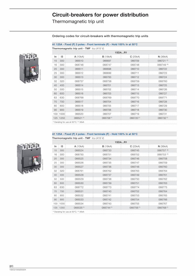
A1 125A - Fixed (F) 3 poles - Front terminals (F) - Hold 100% In at 50°C
Thermomagnetic trip unit - TMF Icu (415 V)
1SDA...R1
In I3 A (10kA) B (18kA) C (25kA) N (36kA)
15 300 066510 066697 066709 066721 (2)
16 300 068746 068747 068748 068749 (2)
20 300 066511 066698 066710 066722
25 300 066512 066699 066711 066723
30 300 066513 066700 066712 066724
32 320 068757 068758 068759 068760
40 400 066514 066701 066713 066725
50 500 066515 066702 066714 066726
60 600 066516 066703 066715 066727
63 630 068768 068769 068770 068771
70 700 066517 066704 066716 066728
80 800 066518 066705 066717 066729
90 900 066519 066706 066718 066730
100 1000 066520 066707 066719 066731
125 1250 066521 (1) 066708 (1) 066720 (1) 066732 (1)
(1) Derating for use at 50°C; (2) 30kA
Circuit-breakers for power distributionThermomagnetic trip unit
A1 125A - Fixed (F) 4 poles - Front terminals (F) - Hold 100% In at 50°C
Thermomagnetic trip unit - TMF Icu (415 V)
1SDA...R1
In I3 A (10kA) B (18kA) C (25kA) N (36kA)
15 300 066524 066733 066745 066757 (2)
16 300 068750 068751 068752 068753 (2)
20 300 066525 066734 066746 066758
25 300 066526 066735 066747 066759
30 300 066527 066736 066748 066760
32 320 068761 068762 068763 068764
40 400 066528 066737 066749 066761
50 500 066529 066738 066750 066762
60 600 066530 066739 066751 066763
63 630 068772 068773 068774 068775
70 700 066531 066740 066752 066764
80 800 066532 066741 066753 066765
90 900 066533 066742 066754 066766
100 1000 066534 066743 066755 066767
125 1250 066535 (1) 066744 (1) 066756 (1) 066768 (1)
(1) Derating for use at 50°C; (2) 30kA
Ordering codes for circuit-breakers with thermomagnetic trip units
Formula_02_gamma.indd 6 21/02/2011 9.38.18
2/7
1SD
C21
0631
F000
1
1SD
C21
0632
F000
1
1SD
C21
0633
F000
1
1SD
C21
0634
F000
1
1SDC210032D0204
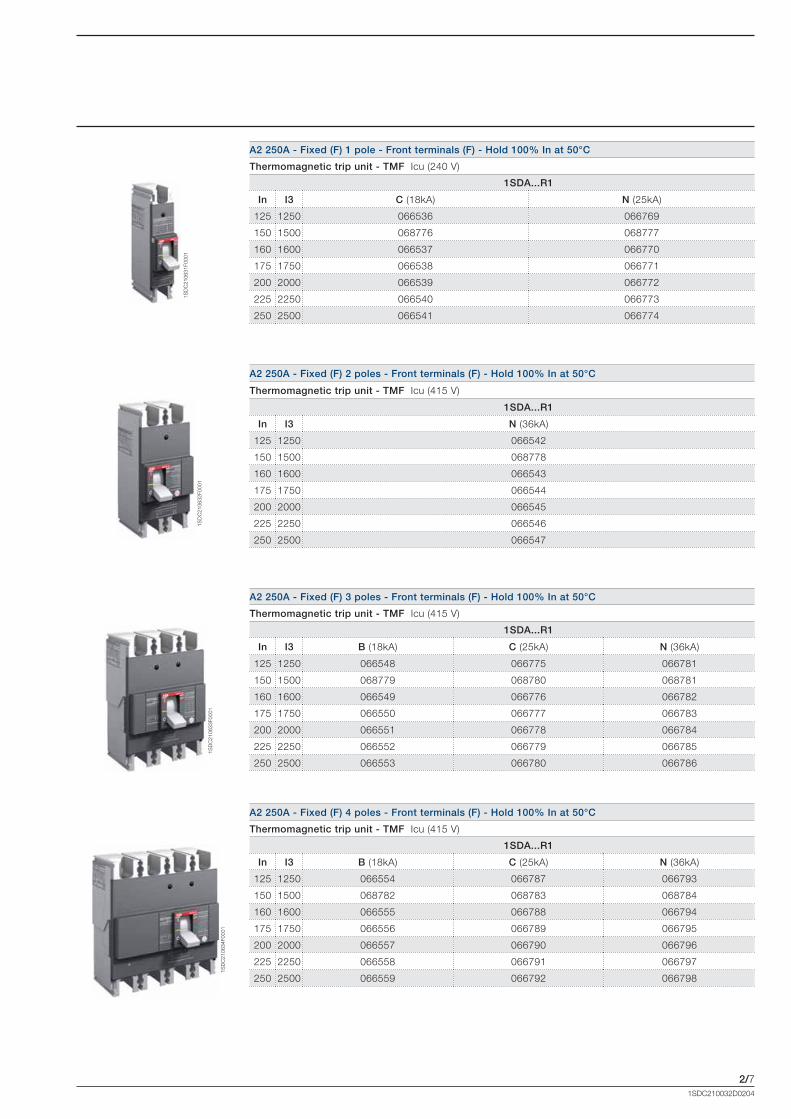
A2 250A - Fixed (F) 3 poles - Front terminals (F) - Hold 100% In at 50°C
Thermomagnetic trip unit - TMF Icu (415 V)
1SDA...R1
In I3 B (18kA) C (25kA) N (36kA)
125 1250 066548 066775 066781
150 1500 068779 068780 068781
160 1600 066549 066776 066782
175 1750 066550 066777 066783
200 2000 066551 066778 066784
225 2250 066552 066779 066785
250 2500 066553 066780 066786
A2 250A - Fixed (F) 1 pole - Front terminals (F) - Hold 100% In at 50°C
Thermomagnetic trip unit - TMF Icu (240 V)
1SDA...R1
In I3 C (18kA) N (25kA)
125 1250 066536 066769
150 1500 068776 068777
160 1600 066537 066770
175 1750 066538 066771
200 2000 066539 066772
225 2250 066540 066773
250 2500 066541 066774
A2 250A - Fixed (F) 2 poles - Front terminals (F) - Hold 100% In at 50°C
Thermomagnetic trip unit - TMF Icu (415 V)
1SDA...R1
In I3 N (36kA)
125 1250 066542
150 1500 068778
160 1600 066543
175 1750 066544
200 2000 066545
225 2250 066546
250 2500 066547
A2 250A - Fixed (F) 4 poles - Front terminals (F) - Hold 100% In at 50°C
Thermomagnetic trip unit - TMF Icu (415 V)
1SDA...R1
In I3 B (18kA) C (25kA) N (36kA)
125 1250 066554 066787 066793
150 1500 068782 068783 068784
160 1600 066555 066788 066794
175 1750 066556 066789 066795
200 2000 066557 066790 066796
225 2250 066558 066791 066797
250 2500 066559 066792 066798
Formula_02_gamma.indd 7 21/02/2011 9.38.21
2/8
1SD
C21
0635
F000
1
1SD
C21
0636
F000
1
1SDC210032D0204
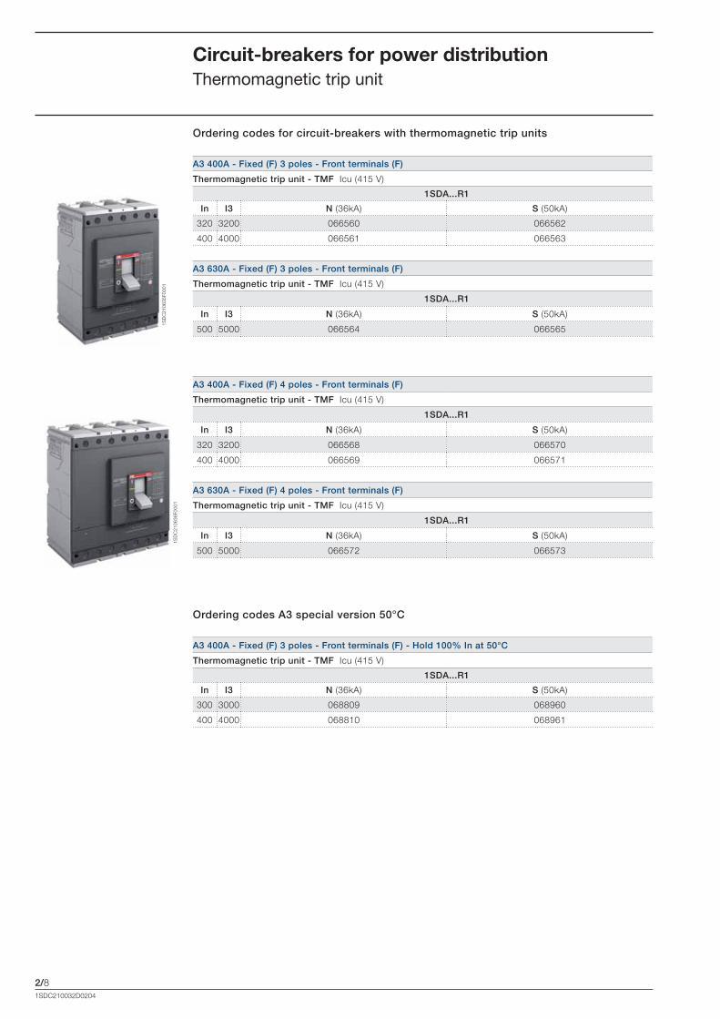
A3 400A - Fixed (F) 3 poles - Front terminals (F)
Thermomagnetic trip unit - TMF Icu (415 V)
1SDA...R1
In I3 N (36kA) S (50kA)
320 3200 066560 066562
400 4000 066561 066563
A3 630A - Fixed (F) 3 poles - Front terminals (F)
Thermomagnetic trip unit - TMF Icu (415 V)
1SDA...R1
In I3 N (36kA) S (50kA)
500 5000 066564 066565
Circuit-breakers for power distributionThermomagnetic trip unit
A3 400A - Fixed (F) 4 poles - Front terminals (F)
Thermomagnetic trip unit - TMF Icu (415 V)
1SDA...R1
In I3 N (36kA) S (50kA)
320 3200 066568 066570
400 4000 066569 066571
A3 630A - Fixed (F) 4 poles - Front terminals (F)
Thermomagnetic trip unit - TMF Icu (415 V)
1SDA...R1
In I3 N (36kA) S (50kA)
500 5000 066572 066573
Ordering codes for circuit-breakers with thermomagnetic trip units
A3 400A - Fixed (F) 3 poles - Front terminals (F) - Hold 100% In at 50°C
Thermomagnetic trip unit - TMF Icu (415 V)
1SDA...R1
In I3 N (36kA) S (50kA)
300 3000 068809 068960
400 4000 068810 068961
Ordering codes A3 special version 50°C
Formula_02_gamma.indd 8 21/02/2011 9.38.22

2/9
1SD
C21
0637
F000
1
1SD
C21
0638
F000
1
1SDC210032D0204
The ELT LI electronic trip unit, only available for A3, provides protection functions against overload L and short-circuit I: • protection against overload (L): fixed threshold I1=630A, with long inverse time trip curve;• protection against short-circuit (I): fixed threshold I3=6000A, with instantaneous time trip curve;• neutral at 100% for four-pole circuit-breakers.
Circuit-breakers for power distributionElectronic trip unit
A3 630A - Fixed (F) 3 poles - Front terminals (F)
Electronic trip unit - ELT LI Icu (415 V)
1SDA...R1
In I3 N (36kA) S (50kA)
630 6000 066566 066567
A3 630A - Fixed (F) 4 poles - Front terminals (F)
Electronic trip unit - ELT LI Icu (415 V)
1SDA...R1
In I3 N (36kA) S (50kA)
630 6000 066574 066575
SACE FORMULA A3 with trip unit ELT LIProtection function Trip threshold Trip curve Excludability Relation
Against overload with long inverse time delay trip according to IEC 60947-2 Standard
Fixed thresholdI1=630A
Tolerance: trip between 1.1...1.30xI1
t1= 12 s at 6xI1Tolerance:
± 10% up to 6xIn± 20% above 6xIn
no t=k/l2
Against short-circuit with instantaneous trip with fixed threshold
Fixed thresholdI3=6000A
Tolerance: ± 10%instantaneous no t=k
Ordering codes for circuit-breakers with electronic trip units
Protection against overload value
Protection against short-circuit value
ELT LI fixed electronic trip unitAn example with SACE FORMULA A3 In=630A
Trip test unit 1SDA...R1
TT1 - Trip test unit 037121
Socket for TT1 test unit
Formula_02_gamma.indd 9 21/02/2011 9.38.25


3/11SDC210032D0204
Accessories
Content
Panorama of accessories ................................................................................................... 3/2
Mechanical accessories
Connection terminals .............................................................................................................. 3/4
Ordering codes ................................................................................................................ 3/6
Terminal covers, phase separators and sealable screws ......................................................... 3/7
Ordering codes ................................................................................................................ 3/7
Rotary handle operating mechanism ....................................................................................... 3/8
Ordering codes ................................................................................................................ 3/8
Front for lever operating mechanism ....................................................................................... 3/9
Ordering codes ................................................................................................................ 3/9
Locks ..................................................................................................................................... 3/9
Ordering codes ................................................................................................................ 3/10
Bracket for fixing onto DIN rail ................................................................................................ 3/11
Ordering codes ................................................................................................................ 3/11
Electrical accessories
Service releases ...................................................................................................................... 3/12
Ordering codes ................................................................................................................ 3/13
Auxiliary contacts for electric signals ....................................................................................... 3/14
Ordering codes ................................................................................................................ 3/14
FORMULA Link ..................................................................................................................... 3/16
Ordering codes ................................................................................................................ 3/19
Formula_03_accessori.indd 1 21/02/2011 9.39.08
3/2
11
11
10
3
1
10
3
1
2
4
4
4
4
7
12
12
78
9
1SD
C21
0639
F000
11S
DC
2106
40F0
001
1SDC210032D0204
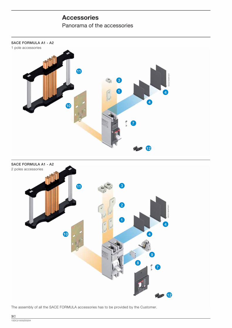
AccessoriesPanorama of the accessories
The assembly of all the SACE FORMULA accessories has to be provided by the Customer.
SACE FORMULA A1 - A2 1 pole accessories
SACE FORMULA A1 - A2 2 poles accessories
Formula_03_accessori.indd 2 21/02/2011 9.39.09
3/3
6
5
7
3
2
1
11
10
9
8
4
4
4
4
7
12
12
12
8
15
14
13
16
16
16
1SD
C21
0641
F000
1
1SDC210032D0204
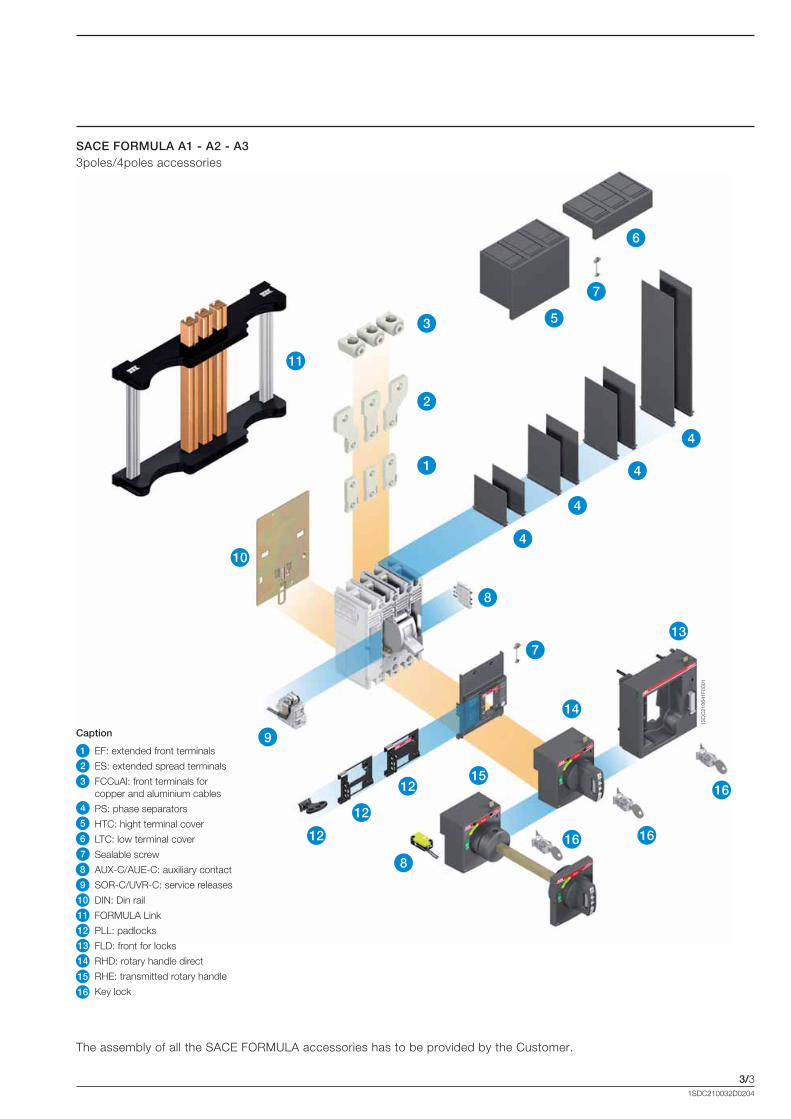
The assembly of all the SACE FORMULA accessories has to be provided by the Customer.
SACE FORMULA A1 - A2 - A3 3poles/4poles accessories
1
Caption
EF: extended front terminals
ES: extended spread terminals
FCCuAl: front terminals for copper and aluminium cables
PS: phase separators
HTC: hight terminal cover
LTC: low terminal cover
Sealable screw
AUX-C/AUE-C: auxiliary contact
SOR-C/UVR-C: service releases
DIN: Din rail
FORMULA Link
PLL: padlocks
FLD: front for locks
RHD: rotary handle direct
RHE: transmitted rotary handle
Key lock
2
3
4
5
6
7
8
9
10
11
12
13
14
15
16
Formula_03_accessori.indd 3 21/02/2011 9.39.10
3/4
1SD
C21
0642
F000
1
1SD
C21
0643
F000
1
1SD
C21
0644
F000
1
1SD
C21
0645
F000
1
1SD
C21
0646
F000
1
1SDC210032D0204
AccessoriesMechanical accessories
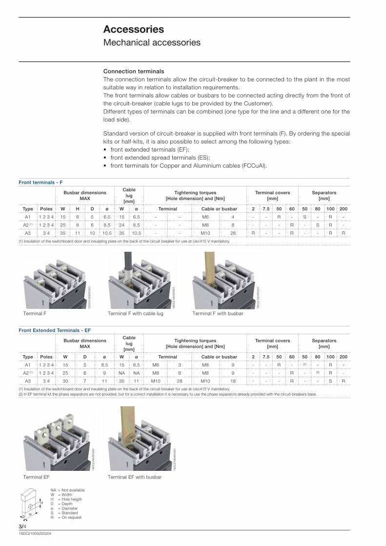
Connection terminalsThe connection terminals allow the circuit-breaker to be connected to the plant in the most suitable way in relation to installation requirements. The front terminals allow cables or busbars to be connected acting directly from the front of the circuit-breaker (cable lugs to be provided by the Customer).Different types of terminals can be combined (one type for the line and a different one for the load side).
Standard version of circuit-breaker is supplied with front terminals (F). By ordering the special kits or half-kits, it is also possible to select among the following types: • front extended terminals (EF);• front extended spread terminals (ES);• front terminals for Copper and Aluminium cables (FCCuAl).
NA = Not availableW = WidthH = Hole heigthD = Depthø = DiameterS = StandardR = On request
Terminal EF Terminal EF with busbar
Terminal F Terminal F with cable lug Terminal F with busbar
Front terminals - F
Busbar dimensions MAX
Cable lug
[mm]
Tightening torques[Hole dimension] and [Nm]
Terminal covers [mm]
Separators [mm]
Type Poles W H D ø W ø Terminal Cable or busbar 2 7.5 50 60 50 80 100 200
A1 1 2 3 4 15 6 5 6.5 15 6.5 - - M6 4 - - R - S - R -
A2 (1) 1 2 3 4 25 8 6 8.5 24 8.5 - - M8 8 - - - R - S R -
A3 3 4 35 11 10 10.5 35 10.5 - - M10 28 R - - R - - R R
(1) Insulation of the switchboard door and insulating plate on the back of the circuit-breaker for use at Ue�415 V mandatory.
Front Extended Terminals - EF
Busbar dimensions MAX
Cable lug
[mm]
Tightening torques[Hole dimension] and [Nm]
Terminal covers[mm]
Separators [mm]
Type Poles W D ø W ø Terminal Cable or busbar 2 7.5 50 60 50 80 100 200
A1 1 2 3 4 15 5 8.5 15 8.5 M6 3 M8 9 - - R - [2] - R -
A2 (1) 1 2 3 4 25 6 9 NA NA M8 8 M8 9 - - - R - [2] R -
A3 3 4 30 7 11 30 11 M10 28 M10 18 - - - R - - S R
(1) Insulation of the switchboard door and insulating plate on the back of the circuit-breaker for use at Ue�415 V mandatory.(2) In EF terminal kit the phase separators are not provided, but for a correct installation it is necessary to use the phase separators already provided with the circuit-breakers base.
H
WD
Formula_03_accessori.indd 4 21/02/2011 9.39.13

3/5
1SD
C21
0647
F000
1
1SD
C21
0648
F000
1
1SD
C21
0649
F000
1
1SD
C21
0650
F000
1
1SD
C21
0651
F000
1
1SD
C21
0652
F000
1
1SD
C21
0653
F000
1
1SDC210032D0204
NA = Not availableW = WidthH = Hole heigthD = Depthø = DiameterS = StandardR = On request
Terminal ES Terminal ES with cable lug Terminal ES with busbar
Terminal FCCuAl Terminal FCCuAl with cable External terminal FCCuAl External terminal FCCuAl with cable
Front Extended Spread Terminal - ES
Busbar dimensions MAX
Cable lug
[mm]
Tightening torques[Hole dimension] and [Nm]
Terminal covers[mm]
Separators[mm]
Type Poles W D ø W ø Terminal Cable or busbar 2 7.5 50 60 50 80 100 200
A1 2 3 4 20 6 8.5 20 8.5 M6 3 M8 9 - - - - - - S -
A2 (1) 2 3 4 30 4 10.5 NA NA M8 8 M10 18 - - - - - - S -
A3 3 4 40 10 11 11 11 M10 28 M10 18 - - - - - - - S
(1) Insulation of the switchboard door and insulating plate on the back of the circuit-breaker for use at Ue�415 V mandatory.
Front Terminals for copper aluminium cables - FCCuAl
Cable [mm2]
Tightening torques[Hole dimension] and [Nm]
Length of Cable
stripping [mm]
Terminal covers[mm]
Separators [mm]
Type Assembly Poles Rigid Flexible Terminal Cable or busbar 2 7.5 50 60 50 80 100 200
A1 Internal 1(1) 2(1) 3 4 1x1..25 1x2.5..25 M6 3 -1-4mm2: 1Nm
5-25mm2: 3Nm16 - S (1) R - - - - -
A1 Internal 1(1) 2(1) 3 4 1x25..50 1x25..50 M6 3 - 3 16 - S (1) R - - - - -
A2 (3) Internal 1(2) 2(2) 3 4 1x50..150 1x70..120 M8 5 - 15 20 - S (1) - R - - - -
A2 (3) Internal 1(2) 2(2) 3 4 1x150..185 - M8 5 - 20 22 - S (1) - R - - - -
A3 Internal 3 4 1x185..300 - M10 18 M16 43 23.5 R - - R - - R R
A3 External 3 4 2x95..240 - M10 18 M22 31 30 1°cable/70 2°cable - - - S - - - -
(1) The Terminal covers are not supplied for 1p and 2p, the use of phase separators, supplied with the standard circuit-breaker, and the insulating of switchboard door are necessary.(2) Insulation plate on the back of the circuit-breaker as mandatory.(3) If terminals are mounted on top of circuit-breaker, Icu=50% and Ics=Icu.
H
WD
Formula_03_accessori.indd 5 21/02/2011 9.39.18

3/61SDC210032D0204
AccessoriesMechanical accessories
Terminals
1SDA...R1
Front terminals - F 1 piece 2 pieces 3 pieces 4 pieces 6 pieces 8 pieces
A1 066200 066201 066202 066203 066204 066205
A2 066206 066207 066208 066209 066210 066211
A3 055012 055013 055010 055011
1SDA...R1
Front Extended Terminals - EF 1 piece 2 pieces 3 pieces 4 pieces 6 pieces 8 pieces
A1 066212 066213 066214 066215 066216 066217
A2 066218 066219 066220 066221 066222 066223
A3 055036 055037 055034 055035
1SDA...R1
Front Extended Spread Terminal - ES 2 pieces 3 pieces 4 pieces(1) 6 pieces 8 pieces
A1 066224 066225 066226 066227 066228
A2 066229 066230 066231 066232 066233
A3 055040 055041 055038 055039
1SDA...R1
Front Terminals for copper aluminium cables - FCCuAl 1 piece 2 pieces 3 pieces 4 pieces 6 pieces 8 pieces
A1 1 x 1...25 mm2 066234 066235 066236 066237 066238 066239
A1 1 x 25...50 mm2 066240 066241 066242 066243 066244 066245
A2 1 x 50...150 mm2 (2) 066246 066247 066248 066249 066250 066251
A2 1 x 125...185 mm2 (2) 066252 066253 066254 066255 066256 066257
A3 1 x 185...300 mm2 055024 055025 055022 055023
A3 2 x 95...240 mm2 055032 055033 055030 055031
(1) 4 poles circuit-breakers only.(2) If terminals are mounted on top of circuit-breaker, Icu=50% and Ics=Icu.
Ordering codes connection terminals
Formula_03_accessori.indd 6 21/02/2011 9.39.19
3/7
1SD
C21
0654
F000
11S
DC
2106
54F0
001
1SD
C21
0655
F000
1
1SD
C21
0656
F000
1
1SD
C21
0657
F000
1
1SD
C21
0658
F000
1
1SDC210032D0204
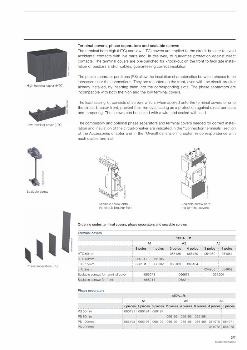
Terminal covers, phase separators and sealable screwsThe terminal both high (HTC) and low (LTC) covers are applied to the circuit-breaker to avoid accidental contacts with live parts and, in this way, to guarantee protection against direct contacts. The terminal covers are pre-punched for knock-out on the front to facilitate instal-lation of busbars and/or cables, guaranteeing correct insulation.
The phase separator partitions (PS) allow the insulation characteristics between phases to be increased near the connections. They are mounted on the front, even with the circuit-breaker already installed, by inserting them into the corresponding slots. The phase separators are incompatible with both the high and the low terminal covers.
The lead sealing kit consists of screws which, when applied onto the terminal covers or onto the circuit-breaker front, prevent their removal, acting as a protection against direct contacts and tampering. The screws can be locked with a wire and sealed with lead.
The compulsory and optional phase separators and terminal covers needed for correct instal-lation and insulation of the circuit-breaker are indicated in the “Connection terminals” section of the Accessories chapter and in the “Overall dimension” chapter, in correspondence with each usable terminal.
Terminal covers
1SDA...R1
A1 A2 A3
3 poles 4 poles 3 poles 4 poles 3 poles 4 poles
HTC 60mm 066186 066189 054960 054961
HTC 50mm 066190 066185
LTC 7.5mm 066181 066182 066183 066184
LTC 2mm 054968 054969
Sealable screws for terminal cover 066673 066673 051504
Sealable screws for front 068214 068214
Phase separators
1SDA...R1
A1 A2 A3
2 pieces 4 pieces 6 pieces 2 pieces 4 pieces 6 pieces 4 pieces 6 pieces
PS 50mm 066191 066194 066197
PS 80mm 066192 066195 066198
PS 100mm 066193 066196 066199 066193 066196 066199 054970 054971
PS 200mm 054972 054973
High terminal cover (HTC)
Low terminal cover (LTC)
Sealable screw
Phase separators (PS)
Ordering codes terminal covers, phase separators and sealable screws
Sealable screw onto the circuit-breaker front
Sealable screw ontothe terminal covers
Formula_03_accessori.indd 7 21/02/2011 9.39.21

3/8
1SD
C21
0659
F000
11S
DC
2106
60F0
001
1SDC210032D0204
AccessoriesMechanical accessories
Rotary handle operating mechanismRotary handle operating mechanism is a control device which allows the circuit-breaker to be operated by means of a rotary handle, which facilitates circuit-breaker opening and closing thanks to its ergonomic handgrip.
There are two types of handle: - direct (RHD): installed directly on the front of the circuit-breaker; - transmitted (RHE): installed on the switchboard door, it acts on the circuit-breaker installed
on the back of the switchboard by means of a transmission rod.
The rotary handles, in the direct and transmitted version, are available for the three-pole and four-pole A1, A2 and A3 circuit-breakers both in the standard version (grey) and in the emer-gency version (red on a yellow background) suitable for controlling machine tools.
Information/settings visible and accessible to the user: • circuit-breaker nameplate;• indication of the 3 positions: open (OFF), closed (ON), tripped (TRIP);• access to the test pushbutton of rotary handle release (only RHD).
The rotary handle operating mechanisms can be ordered: • by using the code of the version already configured (RHD and RHE);• by composing the following three devices (only RHE): – rotary handle on door of the compartment: standard (RHE_H) or emergency (RHE_H_
EM); – transmission rod of 500mm (RHE_S). The minimum and maximum distances between
the fixing surface and the door are 62.5mm and 479.5mm; – base for circuit-breaker (RHE_B).
It is possible to accessorize the handles by means of a vast range of key locks and padlocks. Each rotary handle takes up to maximum 3 padlocks (7mm Ø stem). [See the “Locks” paragraph in the Accessories chapter].
The direct and transmitted rotary handle allows use of the early auxiliary contacts on closing so as to supply the undervoltage release with power early in relation to closing of the main circuit-breaker contacts [see the “Early auxiliary contacts” paragraph in the Accessories chapter].
Rotary Handle
1SDA...R1
A1-A2 A3
RHD - Operating mechanism direct handle 066154 066155
RHD EM - Operating mechanism emergency direct handle 066156 066157
RHE - Operating mechanism transmitted handle 066158 066159
RHE EM - Operating mechanism emergency transmitted handle 066160 066161
RHE_S - Rod transmitted handle 066164 068952
RHE_B - Base transmitted handle 066162 066163
RHE_H - Transmitted handle 066165 066167
RHE_H_EM - Emergency transmitted handle 066166 066168
Direct handle (RHD)
Transmitted handle (RHE)
Ordering codes rotary handle operating mechanism
Formula_03_accessori.indd 8 21/02/2011 9.39.22

3/9
1SD
C21
0661
F000
11S
DC
2106
62F0
001
1SD
C21
0663
F000
11S
DC
2106
64F0
001
1SDC210032D0204
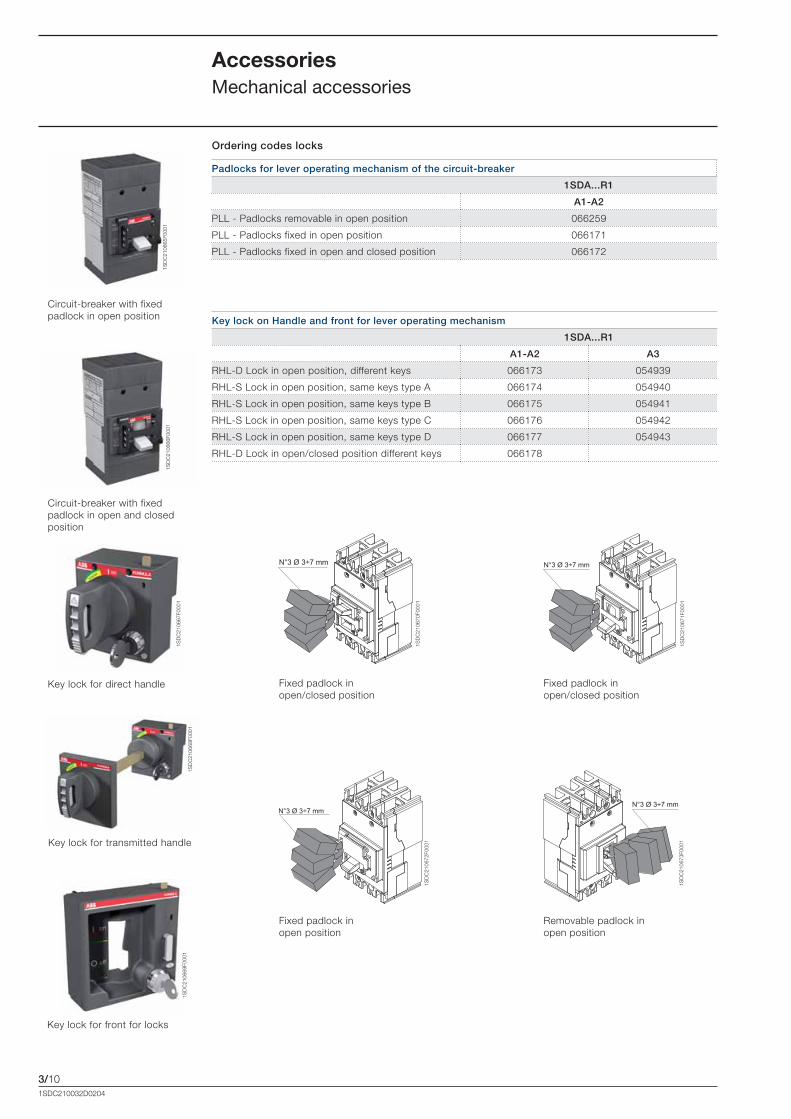
Front for lever operating mechanismDevice which can be installed on the front of the circuit-breaker, which allows the circuit-breaker to be locked with keys and padlocks.
The front for the lever operating mechanism can only be installed on the A3 circuit-breaker in the three-pole or four-pole version. It is possible to lock the front for the lever operating mechanism by means of a vast range of key locks and padlocks. [See the “Locks” paragraph in the Accessories chapter]
Front for operating mechanism
1SDA...R1
A3
FLD - Front for locks 066179
Ordering codes front for lever operating mechanism
LocksDevices (with padlocks or keys) which prevent the circuit-breaker closing or opening opera-tion. They can be applied: • directly onto the front of the circuit-breaker; • onto the direct/transmitted rotary handle operating mechanism; • onto the front for lever operating mechanisms. All the locks of the circuit-breaker in the open position ensure isolation of the circuit accord-ing to the IEC 60947-2 Standard. The locks in closed position do not prevent release of the mechanism following a fault.
Type of lockCircuit-breaker
PolarityOptional/Standard Supply
CB lock position
Type of Lock Withdraw-
ability of Key
Circuit-breaker
PLL- Fixed padlock A1-A2 3, 4 OptionalOPEN-
CLOSEDpadlocks-max 3 padlocks
Ø stem 7mm (not supplied)-
PLL- Fixed padlock A1-A2 3, 4 Optional OPENpadlocks-max 3 padlocks
Ø stem 7mm (not supplied)-
PLL- Removable padlock
A1-A2 1,2,3,4 Optional OPENpadlocks-max 3 padlocks
Ø stem 7mm (not supplied)-
Rotary Handle
Direct and Transmitted
Padlock in open position
A1-A2-A3 3,4 Standard OPENpadlocks-max 3 padlocks
Ø stem 7mm (not supplied)-
Compartment door lock A1-A2-A3 3,4 Standard CLOSED Door lock(1) -
RHL-S Lock with key in open pos.
A1-A2-A3 3,4 Optional OPEN Same Ronis keys OPEN
RHL-D Lock with key in open pos.
A1-A2-A3 3,4 Optional OPEN Different Ronis keys OPEN
RHL-D Lock with key in open and closed position
A1-A2 3,4 OptionalOPEN-
CLOSEDDifferent Ronis keys
OPEN/CLOSED
Front for Lever
Operating Mechanism
Padlock in open position
A3 3,4 Standard OPENpadlocks-max 3 padlocks
Ø stem 6mm (not supplied)-
Compartment door lock A3 3,4 Standard CLOSED Door lock -
RHL-D Lock with key in open pos.
A3 3,4 Optional OPEN Different Ronis keys OPEN
RHL-S Lock with key in open pos.
A3 3,4 Optional OPEN Same Ronis keys OPEN
(1) Function can be completely excluded by the Customer during assembly of the handle [A1 and A2].
Front for locks (FLD)
Fixed padlock in open position (PLL)
Removable padlock in open position (PLL)
Fixed padlock in open and closed position (PLL)
Formula_03_accessori.indd 9 21/02/2011 9.39.24
3/10
1SD
C21
0665
F000
11S
DC
2106
66F0
001
1SD
C21
0667
F000
1
1SD
C21
0668
F000
11S
DC
2106
69F0
001
1SD
C21
0670
F000
1
1SD
C21
0671
F000
1
1SD
C21
0672
F000
1
1SD
C21
0673
F000
1
1SDC210032D0204
AccessoriesMechanical accessories
Key lock for transmitted handle
Key lock for direct handle
Key lock for front for locks
Padlocks for lever operating mechanism of the circuit-breaker
1SDA...R1
A1-A2
PLL - Padlocks removable in open position 066259
PLL - Padlocks fixed in open position 066171
PLL - Padlocks fixed in open and closed position 066172
Key lock on Handle and front for lever operating mechanism
1SDA...R1
A1-A2 A3
RHL-D Lock in open position, different keys 066173 054939
RHL-S Lock in open position, same keys type A 066174 054940
RHL-S Lock in open position, same keys type B 066175 054941
RHL-S Lock in open position, same keys type C 066176 054942
RHL-S Lock in open position, same keys type D 066177 054943
RHL-D Lock in open/closed position different keys 066178
Ordering codes locks
Circuit-breaker with fixed padlock in open position
Circuit-breaker with fixed padlock in open and closed position
Fixed padlock in open/closed position
Fixed padlock in open/closed position
Fixed padlock in open position
Removable padlock in open position
Formula_03_accessori.indd 10 21/02/2011 9.39.28
3/11
1SD
C21
0674
F000
1
1SD
C21
0675
F000
1
1SD
C21
0676
F000
1
1SD
C21
0677
F000
1
1SD
C21
0678
F000
1
1SDC210032D0204
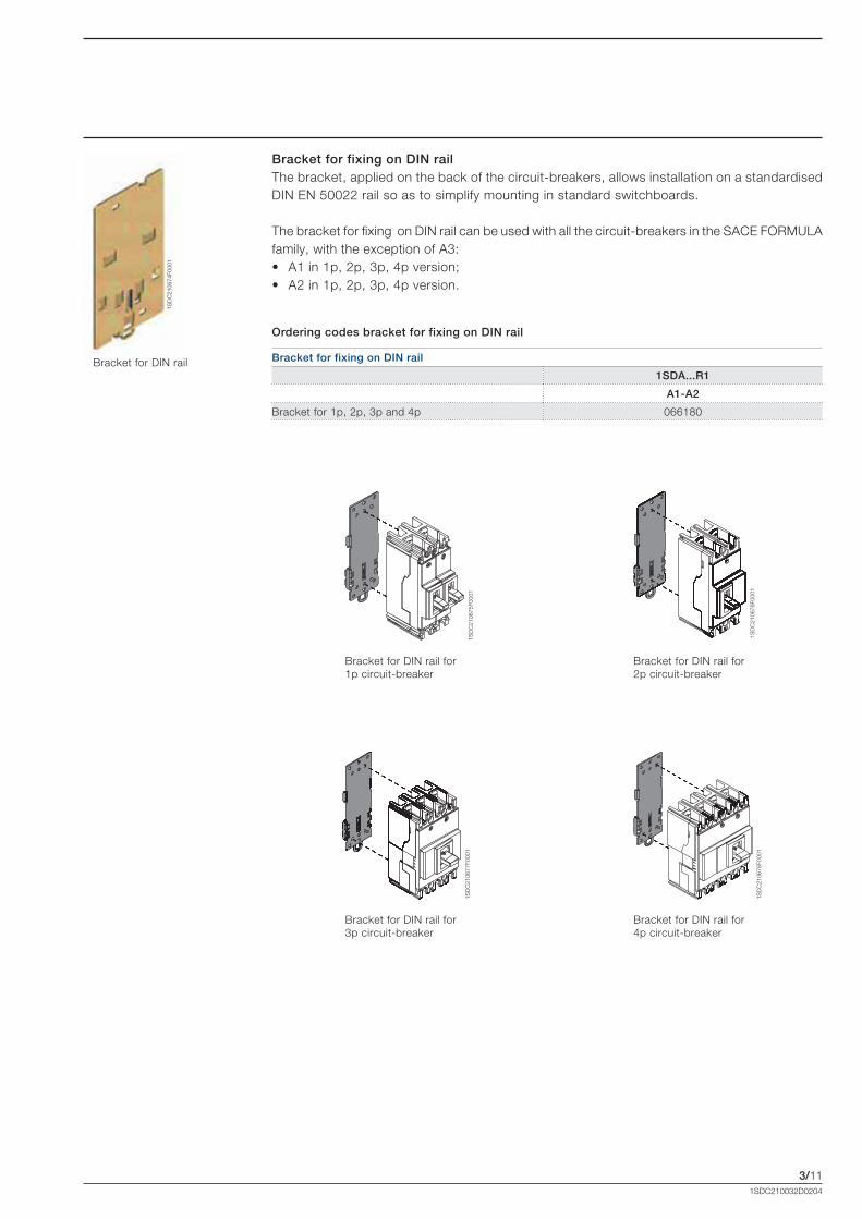
Bracket for fixing on DIN railThe bracket, applied on the back of the circuit-breakers, allows installation on a standardised DIN EN 50022 rail so as to simplify mounting in standard switchboards.
The bracket for fixing on DIN rail can be used with all the circuit-breakers in the SACE FORMULA family, with the exception of A3:• A1 in 1p, 2p, 3p, 4p version; • A2 in 1p, 2p, 3p, 4p version.
Bracket for fixing on DIN rail
1SDA...R1
A1-A2
Bracket for 1p, 2p, 3p and 4p 066180
Bracket for DIN rail
Ordering codes bracket for fixing on DIN rail
Bracket for DIN rail for 1p circuit-breaker
Bracket for DIN rail for 2p circuit-breaker
Bracket for DIN rail for 3p circuit-breaker
Bracket for DIN rail for 4p circuit-breaker
Formula_03_accessori.indd 11 21/02/2011 9.39.30
3/12
1SD
C21
0679
F000
1
1SDC210032D0204
AccessoriesElectrical accessories
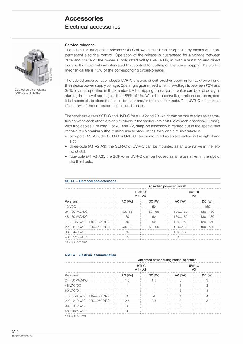
Service releases The cabled shunt opening release SOR-C allows circuit-breaker opening by means of a non-permanent electrical control. Operation of the release is guaranteed for a voltage between 70% and 110% of the power supply rated voltage value Un, in both alternating and direct current. It is fitted with an integrated limit contact for cutting off the power supply. The SOR-C mechanical life is 10% of the corresponding circuit-breaker.
The cabled undervoltage release UVR-C ensures circuit-breaker opening for lack/lowering of the release power supply voltage. Opening is guaranteed when the voltage is between 70% and 35% of Un as specified in the Standard. After tripping, the circuit-breaker can be closed again starting from a voltage higher than 85% of Un. With the undervoltage release de-energised, it is impossible to close the circuit-breaker and/or the main contacts. The UVR-C mechanical life is 10% of the corresponding circuit-breaker.
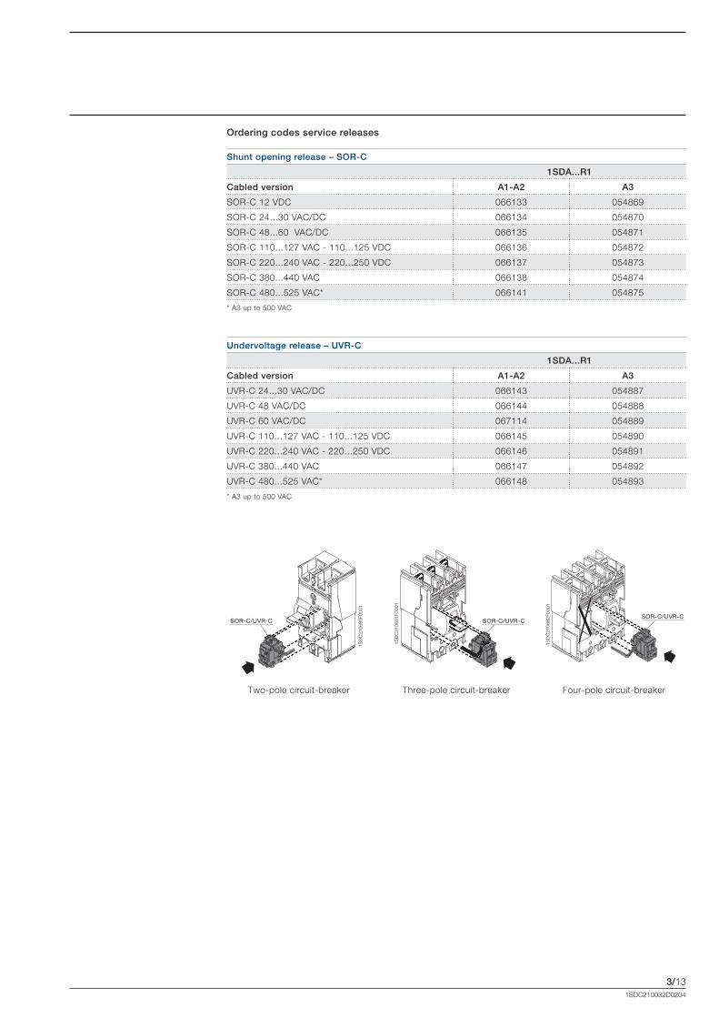
The service releases SOR-C and UVR-C for A1, A2 and A3, which can be mounted as an alterna-tive between each other, are only available in the cabled version (20 AWG cable section/0.5mm2), with free cables 1 m long. For A1 and A2, snap-on assembly is carried out in the special slot of the circuit-breaker without using any screws. In the following circuit-breakers: • two-pole (A1, A2), the SOR-C or UVR-C can be mounted as an alternative in the right-hand
slot; • three-pole (A1 A2 A3), the SOR-C or UVR-C can be mounted as an alternative in the left-
hand slot; • four-pole (A1,A2,A3), the SOR-C or UVR-C can be housed as an alternative, in the slot of
the third pole.
Cabled service release SOR-C and UVR-C
SOR-C – Electrical characteristics
Absorbed power on inrush
SOR-C A1 - A2
SOR-C A3
Versions AC [VA] DC [W] AC [VA] DC [W]
12 VDC 50 150
24...30 VAC/DC 50...65 50...65 130...180 130...180
48...60 VAC/DC 60 60 130...180 130...180
110...127 VAC - 110...125 VDC 50 50 120...150 120...150
220...240 VAC - 220...250 VDC 50...60 50...60 100...150 100...150
380...440 VAC 55 130...180
480...525 VAC* 55 150
* A3 up to 500 VAC
UVR-C – Electrical characteristics
Absorbed power during normal operation
UVR-C A1 - A2
UVR-C A3
Versions AC [VA] DC [W] AC [VA] DC [W]
24...30 VAC/DC 1.5 1.5 3 3
48 VAC/DC 1 1 3 3
60 VAC/DC 1 1 3 3
110...127 VAC - 110...125 VDC 2 2 3 3
220...240 VAC - 220...250 VDC 2.5 2.5 3 3
380...440 VAC 3 3
480...525 VAC* 4 3
* A3 up to 500 VAC
Formula_03_accessori.indd 12 21/02/2011 9.39.31
3/13
SOR-C/UVR-C SOR-C/UVR-CSOR-C/UVR-C
1SD
C21
0680
F000
1
1SD
C21
0681
F000
1
1SD
C21
0682
F000
1
1SDC210032D0204
Two-pole circuit-breaker Three-pole circuit-breaker Four-pole circuit-breaker
Shunt opening release – SOR-C
1SDA...R1
Cabled version A1-A2 A3
SOR-C 12 VDC 066133 054869
SOR-C 24...30 VAC/DC 066134 054870
SOR-C 48...60 VAC/DC 066135 054871
SOR-C 110...127 VAC - 110...125 VDC 066136 054872
SOR-C 220...240 VAC - 220...250 VDC 066137 054873
SOR-C 380...440 VAC 066138 054874
SOR-C 480...525 VAC* 066141 054875
* A3 up to 500 VAC
Undervoltage release – UVR-C
1SDA...R1
Cabled version A1-A2 A3
UVR-C 24...30 VAC/DC 066143 054887
UVR-C 48 VAC/DC 066144 054888
UVR-C 60 VAC/DC 067114 054889
UVR-C 110...127 VAC - 110...125 VDC 066145 054890
UVR-C 220...240 VAC - 220...250 VDC 066146 054891
UVR-C 380...440 VAC 066147 054892
UVR-C 480...525 VAC* 066148 054893
* A3 up to 500 VAC
Ordering codes service releases
Formula_03_accessori.indd 13 21/02/2011 9.39.33

3/14
3Q+1SY (A3)
2Q+1SY (A1,A2)
1Q+1SY (A1,A2,A3)
3Q+1SY (A3)
2Q+1SY (A1,A2)
1Q+1SY (A1,A2,A3)2Q+1SY (A2)
1Q+1SY (A1)
1SD
C21
0683
F000
1
1SD
C21
0684
F000
1
1SD
C21
0685
F000
1
1SD
C21
0686
F000
1
1SDC210032D0204
Auxiliary contacts for the electrical signalsThe auxiliary contacts allow information about the state of the circuit-breaker to be taken outside. The signals available are as follows: • open/closed: signalling the position of the circuit-breaker power contacts (Q);• release trip: signalling circuit-breaker opening due to tripping of the thermomagnetic or
electronic trip unit (due to overload or short-circuit), of the opening of undervoltage release SOR-C or UVR-C, or by activation of the test pushbutton (SY).
Auxiliary contacts AUX-C Q, AUX-C SYInstallation of the auxiliary contacts for A1 and A2 (at 250 VAC/DC) snap-on in the special slot of the circuit-breaker without the of use any screws. All the auxiliary contacts are supplied in the cabled version (20 AWG cable section/0.5mm2), with loose cables 1 m long. The combi-nations of auxiliary contacts available, vary according to the circuit-breaker. In particular, in the following circuit-breakers: • two-pole, the 1Q+1SY (for A1) and 2Q+1SY (for A2) combination is available;• three-pole and four-pole, the 1Q+1SY and 2Q+1SY (for A1 and A2) and 1Q+1SY or 3Q+1SY
(for A3) combination is available.An AUX-C contact is also available as spare part and it can be used as Q or SY according to the slot of the circuit- breaker in which it is inseted.
AccessoriesElectrical accessories
Cabled auxiliary contact
AUX-C – Electrical characteristics
Category of use (G2.13)
[IEC 60947-5-1]Voltage Current
[V] [A]
AC-12/AC-13/AC-14 125 6
AC-15 125 5
AC-12/AC-13/AC-14 250 6
AC-15 250 4
DC-12 110 0,5
DC-14 110 0,05
DC-12 250 0,3
DC-14 250 0,03
Two poles circuit-breaker Three poles circuit-breaker Four poles circuit-breaker
Formula_03_accessori.indd 14 21/02/2011 9.39.36
3/15
1SD
C21
0687
F000
1
1SD
C21
0688
F000
1
1SDC210032D0204
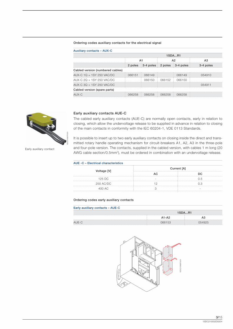
Early auxiliary contacts AUE-C
The cabled early auxiliary contacts (AUE-C) are normally open contacts, early in relation to closing, which allow the undervoltage release to be supplied in advance in relation to closing of the main contacts in conformity with the IEC 60204-1, VDE 0113 Standards.
It is possible to insert up to two early auxiliary contacts on closing inside the direct and trans-mitted rotary handle operating mechanism for circuit-breakers A1, A2, A3 in the three-pole and four-pole version. The contacts, supplied in the cabled version, with cables 1 m long (20 AWG cable section/0.5mm2), must be ordered in combination with an undervoltage release.
AUE -C – Electrical characteristics
Voltage [V]Current [A]
AC DC
125 DC - 0.5
250 AC/DC 12 0.3
400 AC 3 -
Early auxiliary contact
Auxiliary contacts – AUX-C
1SDA...R1
A1 A2 A3
2 poles 3-4 poles 2 poles 3-4 poles 3-4 poles
Cabled version (numbered cables)
AUX-C 1Q + 1SY 250 VAC/DC 066151 066149 066149 054910
AUX-C 2Q + 1SY 250 VAC/DC 066150 066152 066150
AUX-C 3Q + 1SY 250 VAC/DC 054911
Cabled version (spare parts)
AUX-C 066258 066258 066258 066258
Ordering codes auxiliary contacts for the electrical signal
Early auxiliary contacts – AUE-C
1SDA...R1
A1-A2 A3
AUE-C 066153 054925
Ordering codes early auxiliary contacts
Formula_03_accessori.indd 15 21/02/2011 9.39.36
T6
A3
A2
F
LINE
LOAD
LOAD
3/16
1SD
C21
0697
F000
1
1SDC210032D0204
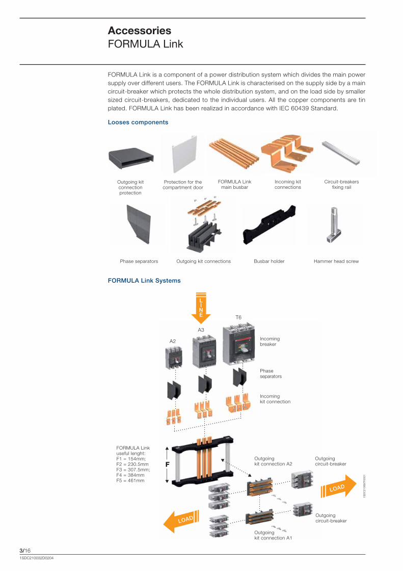
Accessories FORMULA Link
FORMULA Link is a component of a power distribution system which divides the main power supply over different users. The FORMULA Link is characterised on the supply side by a main circuit-breaker which protects the whole distribution system, and on the load side by smaller sized circuit-breakers, dedicated to the individual users. All the copper components are tin plated. FORMULA Link has been realizad in accordance with IEC 60439 Standard.
Looses components
FORMULA Link Systems
Outgoing kit connections Busbar holder Hammer head screwPhase separators
Outgoing circuit-breaker
Outgoing circuit-breaker
FORMULA Link useful lenght: F1 = 154mm; F2 = 230.5mmF3 = 307.5mm; F4 = 384mmF5 = 461mm
Incoming breaker
Incoming kit connection
Phase separators
Outgoing kit connection A2
Outgoing kit connection A1
FORMULA Link main busbar
Incoming kit connections
Circuit-breakers fixing rail
Protection for the compartment door
Outgoing kit connection protection
Formula_03_accessori.indd 16 21/02/2011 9.39.45
1SD
C21
0698
F000
11S
DC
2106
99F0
001
1SD
C21
0691
F000
1
3/171SDC210032D0204
Three different frames of FORMULA Links are available according to the incoming current of the system:• 250A FORMULA Link, usable with SACE FORMULA A2 circuit-breaker as incoming breaker; • 400A FORMULA Link, usable with SACE FORMULA A3 circuit-breaker as incoming breaker; • 630/800A FORMULA Link, usable with SACE Tmax T6 circuit breaker up 800A as incoming
breaker.
FORMULA Link - Mechanical characteristics
FORMULA Link frame [A] 250 400 630/800
Length F1 F2 F3 F4 F5 F1 F2 F3 F4 F5 F1 F2 F3 F4 F5
Number of outgoing circuit-breaker(SACE FORMULA A1)
1p 12 18 24 30 36 12 18 24 30 36 12 18 24 30 36
2p 6 8 12 14 18 6 8 12 14 18 6 8 12 14 18
3p 4 6 8 10 12 4 6 8 10 12 4 6 8 10 12
FORMULA Link - Electrical characteristics
FORMULA Link frame [A] 250 400 630/800
Incoming Breaker A2 A3 T6
Outgoing Breaker A1 A1-A2 A1-A2
Rated Operational Voltage 50/60 Hz [V] 550 AC 550 AC 550 AC
Rated Insulation Voltage [V] 690 AC 690 AC 690 AC
Rated Short Time Withstand Current (1s) [kA] 30 40 40
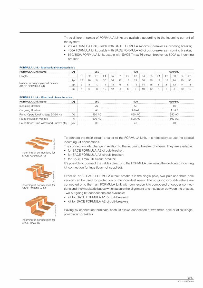
To connect the main circuit-breaker to the FORMULA Link, it is necessary to use the special incoming kit connections. The connection kits change in relation to the incoming breaker choosen. They are available:• for SACE FORMULA A2 circuit-breaker;• for SACE FORMULA A3 circuit-breaker;• for SACE Tmax T6 circuit-breaker;It’s possible to connect the cables directly to the FORMULA Link using the dedicated incoming kit connection for lugs (lugs not supplied).
Either A1 or A2 SACE FORMULA circuit-breakers in the single-pole, two-pole and three-pole version can be used for protection of the individual users. The outgoing circuit-breakers are connected onto the main FORMULA Link with connection kits composed of copper connec-tions and thermoplastic bases which assure the alignment and insulation between the phases. Two outgoing kit connections are available: • kit for SACE FORMULA A1 circuit-breakers;• kit for SACE FORMULA A2 circuit-breakers.
Having six connection terminals, each kit allows connection of two three-pole or of six single-pole circuit-breakers.
Incoming kit connections for SACE FORMULA A2
Incoming kit connections for SACE FORMULA A3
Incoming kit connections for SACE Tmax T6
Formula_03_accessori.indd 17 21/02/2011 9.39.47

F
1SD
C21
0700
F000
1
3/181SDC210032D0204
Accessories FORMULA Link
Each FORMULA Link frame is available in five different useful length for the assembling of the outgoing kit connections:• F1: 154mm;• F2: 230.5mm;• F3: 307.5mm;• F4: 384mm; • F5: 461mm.
The length of the FORMULA Link is connected to the number and type of circuit-breakers (A1 or A2, in single-pole, two-pole or three-pole versions) that have to be installed.
In the table below all the possible combinations of three-pole outgoing circuit-breakers are shown. Starting from the number of outgoing ways required, it is possible to obtain the number of connection kit and the length of the FORMULA Link needed.
Outgoing Ways Number of A1 Outgoing
kit connections
Number of A2 Outgoing
kit connections
Frame lengthNumber A1 3p Number A2 3p
4 0 2 0 F1 [154 mm]0 2 0 1
6 0 3 0F2
[230.5 mm]2 2 1 1
0 4 0 2
8 0 4 0F3
[307.5 mm]4 2 2 1
2 4 1 2
10 0 5 0
F4 [384 mm]
6 2 3 1
4 4 2 2
0 6 0 3
12 0 6 0
F5 [461 mm]
8 2 4 1
6 4 3 2
2 6 1 3
0 8 0 4
FORMULA Link
Formula_03_accessori.indd 18 21/02/2011 9.39.48

3/191SDC210032D0204
During the ordering stage, it is necessary to specify the codes of the following components which are already preassembled:• incoming kit connections according to the incoming current; • outgoing kit connections according to the type and number of outgoing circuit-breakers
(the code of the outgoing kit connection includes the base made of thermoplastic material, copper connections and hammer screws for fixing and six outgoing kit connection protections);
• FORMULA Link frame according to the length needed and the incoming current (the code includes: 3 main busbars, 2 busbars holder supports, 2 circuit-breakers fixing rails, screws, all ready to be assembled).
Incoming kit connections
1SDA...R1
Incoming kit connections A2 066822
Incoming kit connections A3 066823
Incoming kit connections T6 066824
Incoming kit connections FORMULA Link 630/800 for lugs 630/800A 068744
Incoming kit connections FORMULA Link 250 for lugs 250A 068839
Incoming kit connections FORMULA Link 400 for lugs 400A 068840
Outgoing kit connections
1SDA...R1
Outgoing kit connections A1 066841
Outgoing kit connections A2 066842
FORMULA Link frame (ready to be assembled)
1SDA...R1
F1 F2 F3 F4 F5
FORMULA Link 250A for A1 066825 066827 066828 066829 066830
FORMULA Link 400A for A1-A2 066831 066832 066833 066834 066835
FORMULA Link 630/800A for A1-A2 066836 066837 066838 066839 066840
Loose components
1SDA...R1
Aluminium fixing bar L=1.2m 066847
Busbar holder 066843
Busbar 250A L=1.2m 066844
Busbar 400A L=1.2m 066845
Busbar 630/800A L=1.2m 066846
Hammer Head Screws (15 pieces) 066848
Phase separators kit (2 pieces) 067538
Protection for compartment door (2 pieces) L=465mm 067539
Kit protection A1 (15 pieces) 068740
Kit protection A2 (15 pieces) 068741
Ordering code for FORMULA Link
Formula_03_accessori.indd 19 21/02/2011 9.39.48
1SD
C21
0701
F000
1
3/201SDC210032D0204
Accessories FORMULA Link
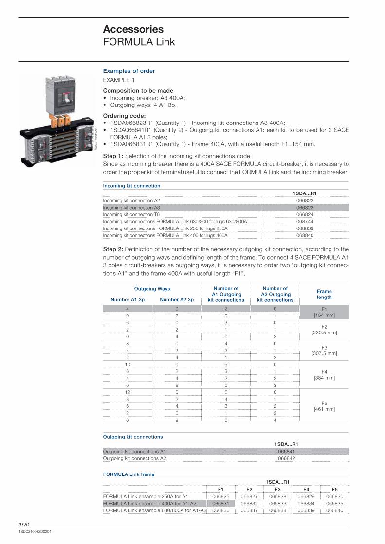
Examples of order
EXAMPLE 1
Composition to be made• Incoming breaker: A3 400A;• Outgoing ways: 4 A1 3p.
Ordering code:• 1SDA066823R1 (Quantity 1) - Incoming kit connections A3 400A;• 1SDA066841R1 (Quantity 2) - Outgoing kit connections A1: each kit to be used for 2 SACE
FORMULA A1 3 poles;• 1SDA066831R1 (Quantity 1) - Frame 400A, with a useful length F1=154 mm.
Step 1: Selection of the incoming kit connections code.Since as incoming breaker there is a 400A SACE FORMULA circuit-breaker, it is necessary to order the proper kit of terminal useful to connect the FORMULA Link and the incoming breaker.
Incoming kit connection
1SDA...R1
Incoming kit connection A2 066822Incoming kit connection A3 066823Incoming kit connection T6 066824Incoming kit connections FORMULA Link 630/800 for lugs 630/800A 068744Incoming kit connections FORMULA Link 250 for lugs 250A 068839Incoming kit connections FORMULA Link 400 for lugs 400A 068840
Step 2: Definiction of the number of the necessary outgoing kit connection, according to the number of outgoing ways and defining length of the frame. To connect 4 SACE FORMULA A1 3 poles circuit-breakers as outgoing ways, it is necessary to order two “outgoing kit connec-tions A1” and the frame 400A with useful length “F1”.
FORMULA Link frame
1SDA...R1
F1 F2 F3 F4 F5
FORMULA Link ensemble 250A for A1 066825 066827 066828 066829 066830FORMULA Link ensemble 400A for A1-A2 066831 066832 066833 066834 066835FORMULA Link ensemble 630/800A for A1-A2 066836 066837 066838 066839 066840
Outgoing Ways Number of A1 Outgoing
kit connections
Number of A2 Outgoing
kit connections
Frame lengthNumber A1 3p Number A2 3p
4 0 2 0 F1 [154 mm]0 2 0 1
6 0 3 0F2
[230.5 mm]2 2 1 10 4 0 28 0 4 0
F3 [307.5 mm]
4 2 2 12 4 1 2
10 0 5 0
F4 [384 mm]
6 2 3 14 4 2 20 6 0 3
12 0 6 0
F5 [461 mm]
8 2 4 16 4 3 22 6 1 30 8 0 4
Outgoing kit connections
1SDA...R1
Outgoing kit connections A1 066841Outgoing kit connections A2 066842
Formula_03_accessori.indd 20 21/02/2011 9.39.49
1SD
C21
0702
F000
1
3/211SDC210032D0204
Examples of order
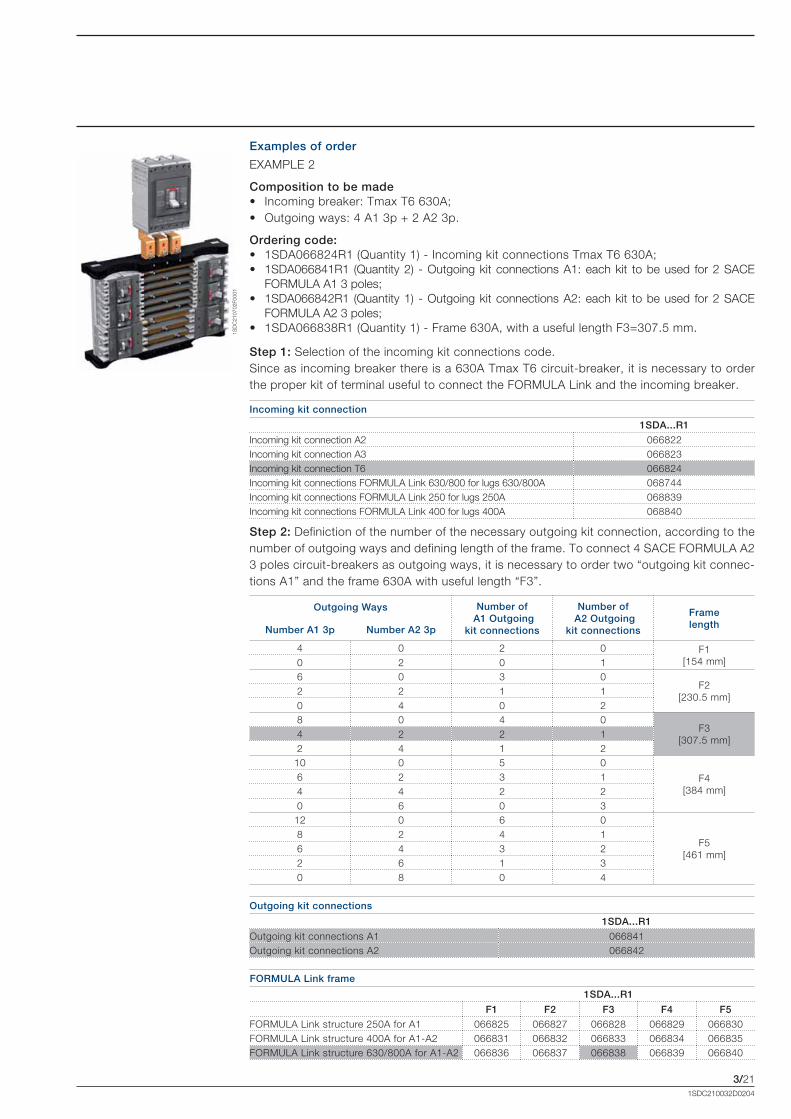
EXAMPLE 2
Composition to be made• Incoming breaker: Tmax T6 630A;• Outgoing ways: 4 A1 3p + 2 A2 3p.
Ordering code:• 1SDA066824R1 (Quantity 1) - Incoming kit connections Tmax T6 630A;• 1SDA066841R1 (Quantity 2) - Outgoing kit connections A1: each kit to be used for 2 SACE
FORMULA A1 3 poles;• 1SDA066842R1 (Quantity 1) - Outgoing kit connections A2: each kit to be used for 2 SACE
FORMULA A2 3 poles;• 1SDA066838R1 (Quantity 1) - Frame 630A, with a useful length F3=307.5 mm.
Step 1: Selection of the incoming kit connections code.Since as incoming breaker there is a 630A Tmax T6 circuit-breaker, it is necessary to order the proper kit of terminal useful to connect the FORMULA Link and the incoming breaker.
Incoming kit connection
1SDA...R1
Incoming kit connection A2 066822Incoming kit connection A3 066823Incoming kit connection T6 066824Incoming kit connections FORMULA Link 630/800 for lugs 630/800A 068744Incoming kit connections FORMULA Link 250 for lugs 250A 068839Incoming kit connections FORMULA Link 400 for lugs 400A 068840
Step 2: Definiction of the number of the necessary outgoing kit connection, according to the number of outgoing ways and defining length of the frame. To connect 4 SACE FORMULA A2 3 poles circuit-breakers as outgoing ways, it is necessary to order two “outgoing kit connec-tions A1” and the frame 630A with useful length “F3”.
FORMULA Link frame
1SDA...R1
F1 F2 F3 F4 F5
FORMULA Link structure 250A for A1 066825 066827 066828 066829 066830FORMULA Link structure 400A for A1-A2 066831 066832 066833 066834 066835FORMULA Link structure 630/800A for A1-A2 066836 066837 066838 066839 066840
Outgoing Ways Number of A1 Outgoing
kit connections
Number of A2 Outgoing
kit connections
Frame lengthNumber A1 3p Number A2 3p
4 0 2 0 F1 [154 mm]0 2 0 1
6 0 3 0F2
[230.5 mm]2 2 1 10 4 0 28 0 4 0
F3 [307.5 mm]
4 2 2 12 4 1 2
10 0 5 0
F4 [384 mm]
6 2 3 14 4 2 20 6 0 3
12 0 6 0
F5 [461 mm]
8 2 4 16 4 3 22 6 1 30 8 0 4
Outgoing kit connections
1SDA...R1
Outgoing kit connections A1 066841Outgoing kit connections A2 066842
Formula_03_accessori.indd 21 21/02/2011 9.39.49

Formula_03_accessori.indd 22 21/02/2011 9.39.50

4/11SDC210032D0204
Characteristic curves and technical information
Content
Examples of curve readings ............................................................................................. 4/2
Temperature performance ................................................................................................ 4/3
Trip curves for power distribution
Trip curves with thermomagnetic and electronic trip units ................................................ 4/5
Specific let-through energy curves
230V ..................................................................................................................................... 4/5
415V - 440V .......................................................................................................................... 4/6
500V - 550V .......................................................................................................................... 4/7
Limitations curves
230V ..................................................................................................................................... 4/8
415V - 440V .......................................................................................................................... 4/9
500V - 550V .......................................................................................................................... 4/10
Technical Information
Dissipated powers ............................................................................................................... 4/13
Coordination tables (back-up)
Notes for use ......................................................................................................................... 4/14
MCCB-MCB (415V) ............................................................................................................... 4/15
MCCB-MCCB (415V) ............................................................................................................ 4/16
Formula_04_curve.indd 1 21/02/2011 9.40.23
4/2
t [s]
x I110
10-1
10-2
102
1
10
102
103
104
110-1
~200s
~9.9s
~62.5s
2 x I1
1 10Irms [kA]
1
10
2 5 20 50 100
102
10-1
10-2
I2t[106·A2s]
125A0.70
1 101
10
2 5 20 50 100
102Ip[kA]
Irms [kA]
125A
= 25kA
~ 15kA
40kA
Curve A
Curve B
1SD
C21
0703
F000
11S
DC
2107
04F0
001
1SD
C21
0705
F000
1
1SDC210032D0204
Examples of curve reading
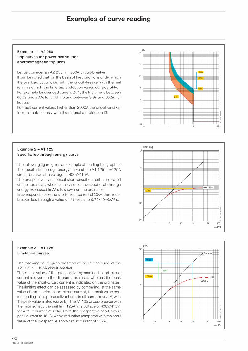
Example 1 – A2 250 Trip curves for power distribution (thermomagnetic trip unit)
Let us consider an A2 250In = 200A circuit-breaker.It can be noted that, on the basis of the conditions under which the overload occurs, i.e. with the circuit-breaker with thermal running or not, the time trip protection varies considerably.For example for overload current 2xI1, the trip time is between 65.2s and 200s for cold trip and between 9.9s and 65.2s for hot trip.For fault current values higher than 2000A the circuit-breaker trips instantaneously with the magnetic protection I3.
Example 2 – A1 125Specific let-through energy curve
The following figure gives an example of reading the graph of the specific let-through energy curve of the A1 125 In=125A circuit-breaker at a voltage of 400V/415V.The prospective symmetrical short-circuit current is indicated on the abscissas, whereas the value of the specific let-through energy expressed in A² s is shown on the ordinates.In correspondence with a short-circuit current of 20kA, the circuit-breaker lets through a value of I² t equal to 0.70x10^6xA² s.
Example 3 – A1 125Limitation curves
The following figure gives the trend of the limiting curve of the A2 125 In = 125A circuit-breaker. The r.m.s. value of the prospective symmetrical short-circuit current is given on the diagram abscissas, whereas the peak value of the short-circuit current is indicated on the ordinates.The limiting effect can be assessed by comparing, at the same value of symmetrical short-circuit current, the peak value cor-responding to the prospective short-circuit current (curve A) with the peak value limited (curve B). The A1 125 circuit-breaker with thermomagnetic trip unit In = 125A at a voltage of 400V/415V, for a fault current of 20kA limits the prospective short-circuit peak current to 15kA, with a reduction compared with the peak value of the prospective short-circuit current of 25kA.
Formula_04_curve.indd 2 21/02/2011 9.40.24

4/31SDC210032D0204
All the SACE FORMULA circuit-breakers can be used under the following environmental conditions:• -25 °C +70 °C: range of temperature where the circuit-breaker is installed;• -40 °C +70 °C: range of temperature where the circuit-breaker is stored.
The SACE FORMULA circuit breaker has been designed to hold 100% In at 50°C without tripping in normal condition (except for A1 125A). To determinate tripping time using time/current curves, use I t°C values indicated in the tables below.
Temperature performances
SACE FORMULA A1 circuit-breaker with termomagnetic trip unit TMF In [A] 10°C 20°C 30°C 40°C 50°C 60°C 70°C
5 6.5 6.1 5.8 5.4 5 4.8 4.510 12.9 12.2 11.5 10.8 10 9.6 9.015 19.4 18.4 17.3 16.2 15 14.4 13.516 20.7 19.6 18.5 17.3 16 15.3 14.420 24.6 23.5 22.4 21.2 20 19.2 18.025 29.2 28.2 27.2 25.9 25 24.0 22.530 36.8 35.3 33.6 31.8 30 28.8 27.032 39.3 37.6 35.9 33.9 32 30.7 28.840 46.7 45.2 43.5 41.5 40 38.3 36.050 58.3 56.5 54.3 51.9 50 47.9 45.060 70.0 67.8 65.2 62.2 60 57.5 54.063 73.5 71.2 68.5 65.4 63 60.4 56.770 81.7 79.1 76.1 72.6 70 67.1 63.080 91.0 88.5 85.6 82.1 80 76.7 72.090 102.4 99.6 96.3 92.4 90 86.3 81.0
100 116.7 113.0 108.7 103.7 100 95.9 90.0125 146.6 139.8 132.6 125.0 116.9 108.3 98.8
SACE FORMULA A2 circuit-breaker with termomagnetic trip unit TMFIn [A] 10°C 20°C 30°C 40°C 50°C 60°C 70°C125 161 153 144 135 125 114 102150 184 176 168 159 150 138 126160 196 188 179 169 160 148 135175 215 206 196 185 175 160 144200 246 235 224 212 200 183 165225 290 276 260 243 225 205 184250 323 306 289 270 250 228 204
SACE FORMULA A3 circuit-breaker with termomagnetic trip unit TMFIn [A] 10°C 20°C 30°C 40°C 50°C 60°C 70°C320 368 350 335 320 305 285 263400 465 442 420 400 380 355 325500 620 580 540 500 450 400 345
The circuit-breaker fitted with electronic trip units do not undergo any variations in performance as the temperature varies, but in the case of temperatures exceeding +40°C, the used rated current must be reduced to protect the copper parts of the circuit-breaker.
SACE FORMULA A3 circuit-breaker with termomagnetic trip unit TMF (special version 50°C)In [A] 10°C 20°C 30°C 40°C 50°C 60°C 70°C300 393 372 350 326 300 272 241400 516 490 462 432 400 365 327
SACE FORMULA A3 circuit-breakers with electronic trip unit ELT LI
In [A] 35°C 40°C 45°C 50°C 55°C 60°C 65°C 70°C630 630 630 630 580 555 529 502 478
Formula_04_curve.indd 3 21/02/2011 9.40.24
4/4
1SD
C21
0706
BF0
001
t [s]
x I110
10-1
10-2
103102
1
10
102
103
104
110-1 I/I1=2.86
t=20s
t=1,2s
1SD
C21
0706
AF0
001
t [s]
x I110
10-1
10-2
103102
1
10
102
103
104
110-1
t=28s
t=1,5s
I/I1=2.75
1SDC210032D0204
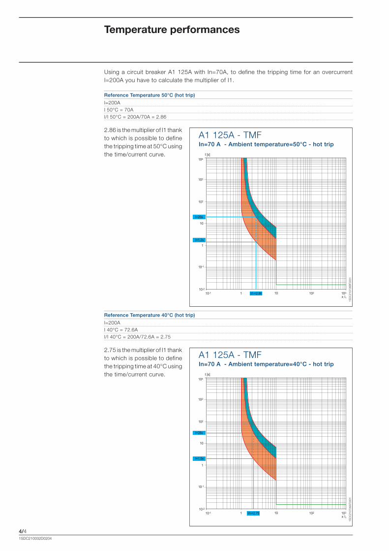
2.86 is the multiplier of I1 thank to which is possible to define the tripping time at 50°C using the time/current curve.
Reference Temperature 50°C (hot trip)
I=200A I 50°C = 70A I/I 50°C = 200A/70A = 2.86
Using a circuit breaker A1 125A with In=70A, to define the tripping time for an overcurrent I=200A you have to calculate the multiplier of I1.
2.75 is the multiplier of I1 thank to which is possible to define the tripping time at 40°C using the time/current curve.
Reference Temperature 40°C (hot trip)
I=200A I 40°C = 72.6A I/I 40°C = 200A/72.6A = 2.75
Temperature performances
A1 125A - TMFIn=70 A - Ambient temperature=50°C - hot trip
A1 125A - TMFIn=70 A - Ambient temperature=40°C - hot trip
Formula_04_curve.indd 4 21/02/2011 9.40.25

4/5
t [s]
x I110
10-1
10-2
103102
1
10
102
103
104
110-1
In=15AIn=16AIn=20AIn=25A
In=30-70A
t [s]
x I110
10-1
10-2
103102
1
10
102
103
104
110-1
t [s]
x I110
10-1
10-2
103102
1
10
102
103
104
110-1
t [s]
x I110
10-1
10-2
103102
1
10
102
103
104
110-1
1SD
C21
0706
F000
1
1SD
C21
0707
F000
1
1SD
C21
0708
F000
1
1SD
C21
0709
F000
1
1SDC210032D0204
Trip curvesTrip curves with thermomagnetic and electronic trip units
A1 125A - TMFIn=15÷70 A
I3= 300A for In <25I3=10In for In�30A
A1 125A - TMFIn=125 A
I3=10In
A2 250A - TMFIn=125÷250 A
I3=10In
A1 125A - TMFIn=80÷100 A
I3=10In
Formula_04_curve.indd 5 21/02/2011 9.40.26

4/6
A3 630A - TMFIn=320÷500 A
I3=10In
t [s]
x I110
10-1
10-2
103102
1
10
102
103
104
110-1
1SD
C21
0710
F000
1
1SD
C21
0710
AF0
001
A3 630A - ELT LI
I3=10In
t [s]
x In10
10-1
10-2
103102
1
10
102
103
104
110-1
1SD
C21
0711
F000
1
t [s]
x I110
10-1
10-2
103102
1
10
102
103
104
110-1
1SDC210032D0204
Trip curvesTrip curves with thermomagnetic and electronic trip units
A3 630A - TMFSpecial version 50°CIn=300÷400 A
I3=10In
Formula_04_curve.indd 6 21/02/2011 9.40.27
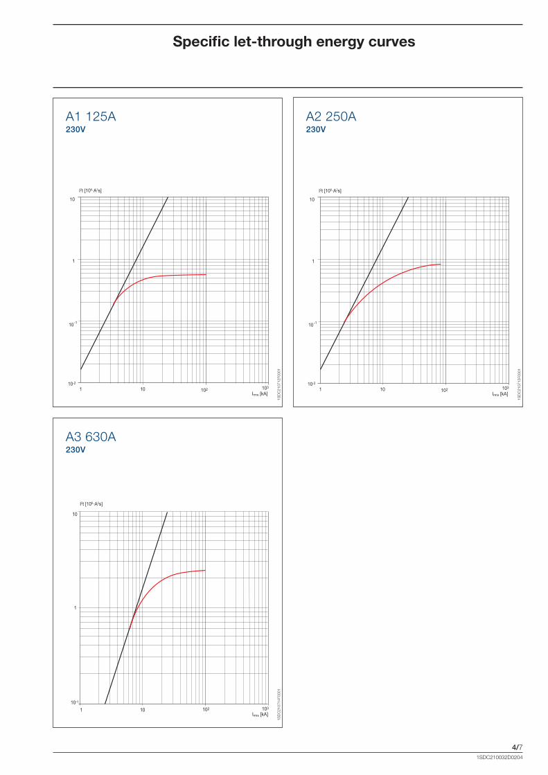
4/7
A1 125A230V
A2 250A230V
A3 630A230V
1Irms [kA]
10 102 10310-2
10 -1
1
10
I2t [106·A2s]
1Irms [kA]
10 102 10310-2
10 -1
1
10
I2t [106·A2s]
1 10
1
10
102Irms [kA]
10310-1
I2t [106·A2s]
1SD
C21
0712
F000
1
1SD
C21
0713
F000
1
1SD
C21
0714
F000
1
1SDC210032D0204
Specific let-through energy curves
Formula_04_curve.indd 7 21/02/2011 9.40.28
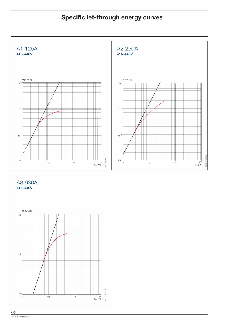
4/8
A1 125A415-440V
A2 250A415-440V
A3 630A415-440V
1 10
1
10
102Irms [kA]
10310-1
I2t [106·A2s]
1Irms [kA]
10 102 10310-2
10 -1
1
10
I2t [106·A2s]
1Irms [kA]
10 102 10310-2
10 -1
1
10
I2t [106·A2s]
1SD
C21
0715
F000
1
1SD
C21
0716
F000
1
1SD
C21
0717
F000
1
1SDC210032D0204
Specific let-through energy curves
Formula_04_curve.indd 8 21/02/2011 9.40.29
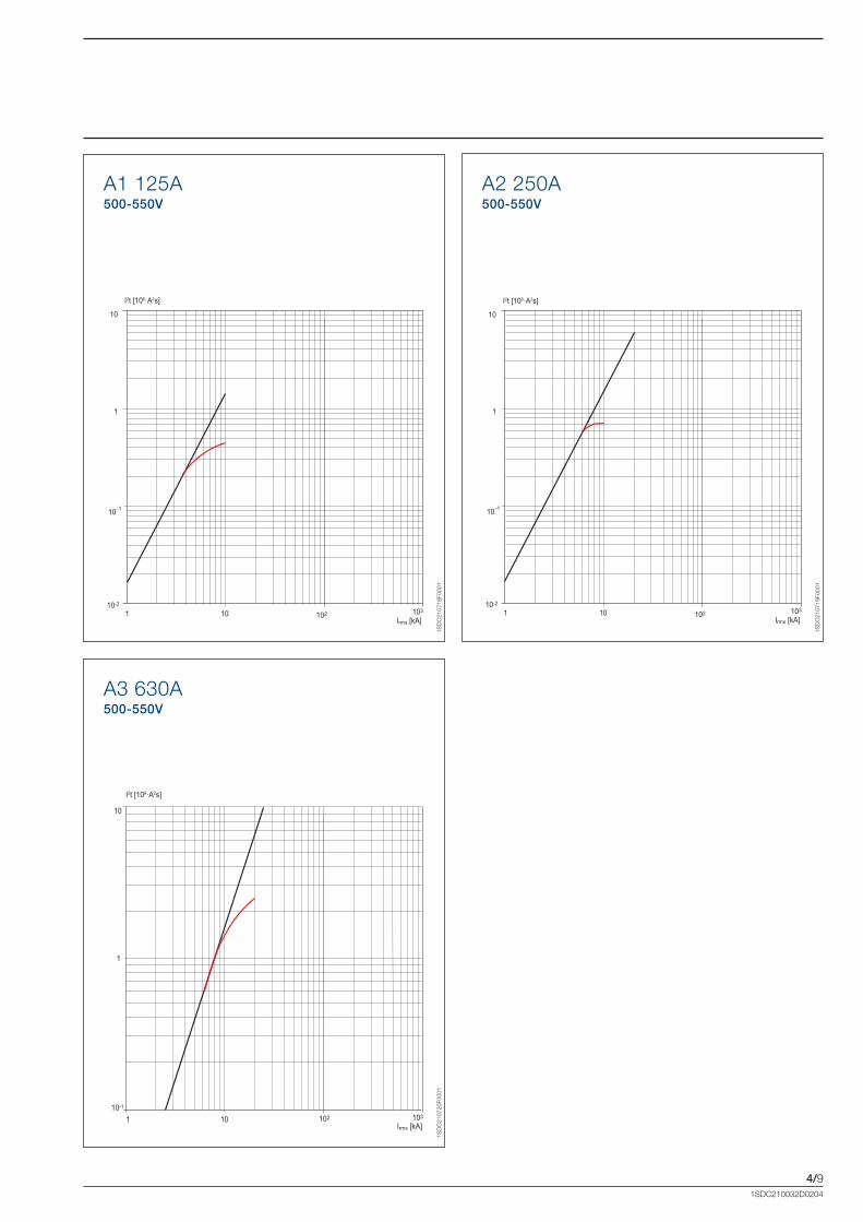
4/9
A1 125A500-550V
A2 250A500-550V
A3 630A500-550V
1Irms [kA]
10 102 10310-2
10 -1
1
10
I2t [106·A2s]
1Irms [kA]
10 102 10310-2
10 -1
1
10
I2t [106·A2s]
1 10
1
10
102Irms [kA]
10310-1
I2t [106·A2s]
1SD
C21
0718
F000
1
1SD
C21
0719
F000
1
1SD
C21
0720
F000
1
1SDC210032D0204
Formula_04_curve.indd 9 21/02/2011 9.40.30

4/10
A1 125A230V
A2 250A230V
A3 630A230V
1 10
102
1
10
102Irms [kA]
103
Ip [kA]Curve A
Curve B
1Irms [kA]
10 1021
10
102
Ip [kA]
103
103
Curve A
Curve B
1SD
C21
0721
F000
1
1SD
C21
0722
F000
1
1SD
C21
0723
F000
1
1Irms [kA]
10 1021
10
102
Ip [kA]
103
103
Curve A
Curve B
1SDC210032D0204
Limitation Curves
Formula_04_curve.indd 10 21/02/2011 9.40.31

4/11
A1 125A415-440V
A2 250A415-440V
A3 630A415-440V
1 10
102
1
10
102Irms [kA]
103
Ip [kA]Curve A
Curve B
1Irms [kA]
10 1021
10
102
Ip [kA]
103
103
Curve A
Curve B
1Irms [kA]
10 1021
10
102
Ip [kA]
103
103
Curve A
Curve B
1SD
C21
0724
F000
1
1SD
C21
0725
F000
1
1SD
C21
0726
F000
1
1SDC210032D0204
Formula_04_curve.indd 11 21/02/2011 9.40.32

4/12
A1 125A500-550V
A2 250A500-550V
A3 630A500-550V
1 10
102
1
10
102Irms [kA]
103
Ip [kA]Curve A
Curve B
1Irms [kA]
10 1021
10
102
Ip [kA]
103
103
Curve A
Curve B
1Irms [kA]
10 1021
10
102
Ip [kA]
103
103
Curve A
Curve B
1SD
C21
0727
F000
1
1SD
C21
0728
F000
1
1SD
C21
0729
F000
1
1SDC210032D0204
Limitation Curves
Formula_04_curve.indd 12 21/02/2011 9.40.33
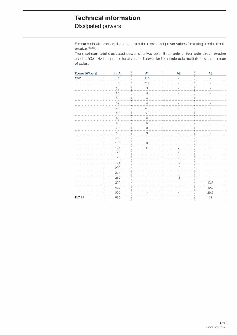
4/131SDC210032D0204
For each circuit-breaker, the table gives the dissipated power values for a single pole circuit-breaker (G2.12). The maximum total dissipated power of a two-pole, three-pole or four-pole circuit-breaker used at 50/60Hz is equal to the dissipated power for the single pole multiplied by the number of poles.
Technical information Dissipated powers
Power [W/pole] In [A] A1 A2 A3
TMF 15 2.5 - -
16 2.8 - -
20 3 - -
25 3 - -
30 4 - -
32 4 - -
40 4.5 - -
50 5.5 - -
60 6 - -
63 6 - -
70 8 - -
80 9 - -
90 7 - -
100 8 - -
125 11 7 -
150 - 8 -
160 - 9 -
175 - 10 -
200 - 12 -
225 - 14 -
250 - 16 -
320 - - 13.6
400 - - 19.5
500 - - 28.8
ELT LI 630 - - 41
Formula_04_curve.indd 13 21/02/2011 9.40.33

4/141SDC210032D0204
Coordination tables (back-up) Notes for use
Back-up protectionThe tables given provide the value (in kA, referring to the breaking capacity according to the IEC 60947-2 Standard) for which the back-up protection among the combination of selected circuit-breakers is verified. The tables cover the possible combinations between ABB SACE FORMULA series of moulded-case circuit-breakers and those between the above mentioned circuit-breakers and the ABB series of miniature circuit-breakers. The values indicated in the tables refer to the voltage Vn of 400/415V AC for all the other coordinations.
NoteThe following tables give the breaking capacities at 415V AC for circuit-breakers SACE FORMULA.
FORMULA @ 415V AC
Versions Icu [kA]
A 10
B 18
C 25
N 36
S 50
CaptionMCB = miniature circuit-breakers (S2, S800)MCCB = moulded-case circuit-breakers (FORMULA)
For miniature circuit-breakers:B = trip characteristic (Im=3...5In)C = trip characteristic (Im=5...10In)D = trip characteristic (Im=10...20In)K = trip characteristic (Im=8...14In)Z = trip characteristic (Im=2...3In)
For solutions not shown in these tables, please contact ABB SACE Division.
Formula_04_curve.indd 14 21/02/2011 9.40.33

4/151SDC210032D0204
Back-upSupply side circuit-breaker: MCCBLoad side circuit-breaker: MCB
MCCB-MCB @ 415 V
Supply S. A1 A2 A1 A2 A1 A2
Version B C N
Load S. Char. In (A) Icu (kA) 18 25 36
S200 B,C,K,Z0.5…10
1016 16 25 25 30 36
13...63
S200M B,C 0.5…10
1516 16 25 25 30 36
13...63
S200P B,C,D,K,Z
0.5…1025
30 36
13...25 30 36
32…63 15 16 16 25 25 30 36
S280 B,C 80…100 6 16 16 16 16 16 36
S290 C,D 80…125 15 16 16 25 25 30 36
S800N B,C,D 10…125 36
S800S B,C,D,K 10…125 50
Coordination tables (back-up) MCCB - MCB (415V)
Formula_04_curve.indd 15 21/02/2011 9.40.33
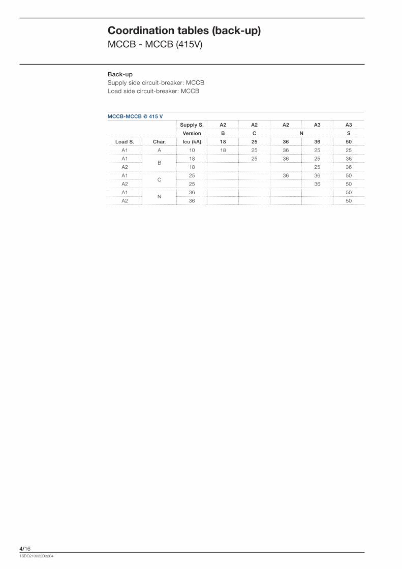
4/161SDC210032D0204
Coordination tables (back-up) MCCB - MCCB (415V)
Back-upSupply side circuit-breaker: MCCBLoad side circuit-breaker: MCCB
MCCB-MCCB @ 415 V
Supply S. A2 A2 A2 A3 A3
Version B C N S
Load S. Char. Icu (kA) 18 25 36 36 50
A1 A 10 18 25 36 25 25
A1B
18 25 36 25 36
A2 18 25 36
A1C
25 36 36 50
A2 25 36 50
A1N
36 50
A2 36 50
Formula_04_curve.indd 16 21/02/2011 9.40.33

5/11SDC210032D0204
Wiring diagrams
Content
Information for reading and graphic symbols .................................................................... 5/2
Wiring diagrams of the circuit-breakers .............................................................................. 5/3
Electrical accessories .......................................................................................................... 5/4
Formula_05_schemi.indd 1 21/02/2011 9.41.17
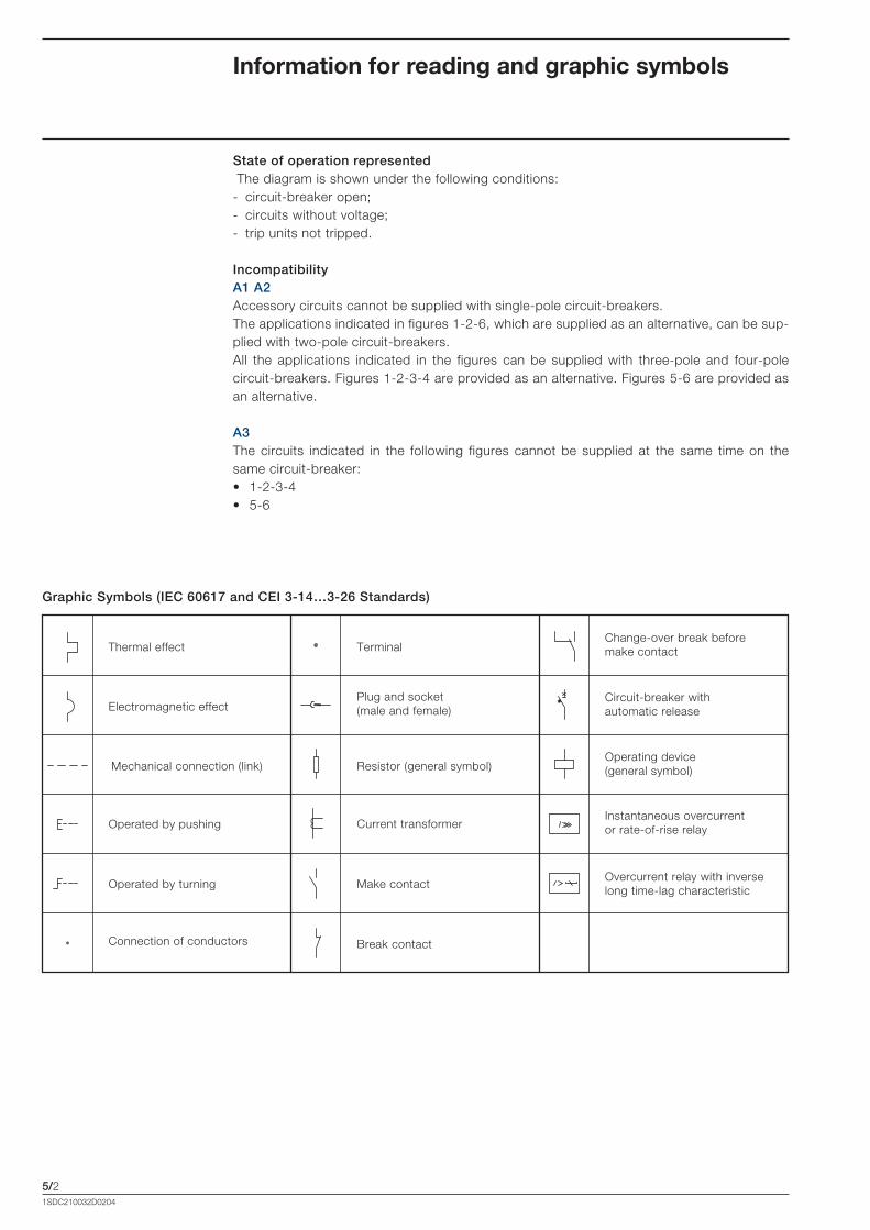
5/21SDC210032D0204
Information for reading and graphic symbols
Graphic Symbols (IEC 60617 and CEI 3-14…3-26 Standards)
Thermal effect
Electromagnetic effect
Mechanical connection (link)
Operated by pushing
Plug and socket(male and female)
Resistor (general symbol)
Make contact
Break contact
Terminal
Circuit-breaker with automatic release
Operating device(general symbol)
Change-over break before make contact
Connection of conductors
State of operation represented The diagram is shown under the following conditions:- circuit-breaker open;- circuits without voltage;- trip units not tripped.
Incompatibility A1 A2Accessory circuits cannot be supplied with single-pole circuit-breakers.The applications indicated in figures 1-2-6, which are supplied as an alternative, can be sup-plied with two-pole circuit-breakers.All the applications indicated in the figures can be supplied with three-pole and four-pole circuit-breakers. Figures 1-2-3-4 are provided as an alternative. Figures 5-6 are provided as an alternative.
A3The circuits indicated in the following figures cannot be supplied at the same time on the same circuit-breaker:• 1-2-3-4• 5-6
Operated by turning
Current transformerInstantaneous overcurrent or rate-of-rise relay
Overcurrent relay with inverse long time-lag characteristic
Formula_05_schemi.indd 2 21/02/2011 9.41.18
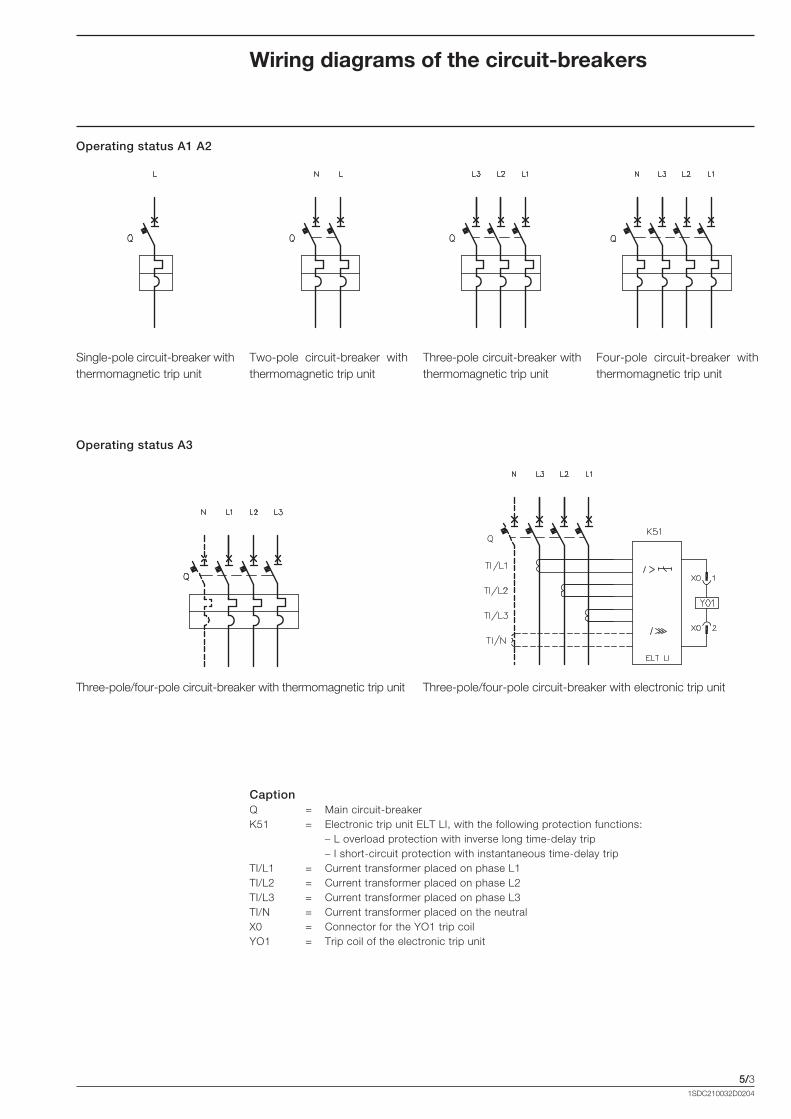
5/31SDC210032D0204
Wiring diagrams of the circuit-breakers
Operating status A1 A2
Single-pole circuit-breaker with thermomagnetic trip unit
Two-pole circuit-breaker with thermomagnetic trip unit
Three-pole circuit-breaker with thermomagnetic trip unit
Four-pole circuit-breaker with thermomagnetic trip unit
Operating status A3
Three-pole/four-pole circuit-breaker with thermomagnetic trip unit Three-pole/four-pole circuit-breaker with electronic trip unit
CaptionQ = Main circuit-breaker K51 = Electronic trip unit ELT LI, with the following protection functions: – L overload protection with inverse long time-delay trip – I short-circuit protection with instantaneous time-delay trip TI/L1 = Current transformer placed on phase L1TI/L2 = Current transformer placed on phase L2TI/L3 = Current transformer placed on phase L3TI/N = Current transformer placed on the neutralX0 = Connector for the YO1 trip coilYO1 = Trip coil of the electronic trip unit
Formula_05_schemi.indd 3 21/02/2011 9.41.19

5/41SDC210032D0204
Electrical accessories
Shunt opening and undervoltage releases A1 A2
Figure: 1) Shunt opening release (SOR-C o YO)2) Undervoltage release (UVR-C o YU)3) Instantaneous undervoltage release with an early contact in series (AUE-C+UVR-C)4) Instantaneous undervoltage release with two early contacts in series (AUE-C+UVR-C)
Notes B) The undervoltage release is supplied for power supply branched on the supply side of the circuit-breaker
or from an independent source: circuit-breaker closing is only allowed with the release energised (the lock on closing is made mechanically).
C) The S4/1 and S4/2 contacts shown in figures 3-4 open the circuit with circuit-breaker open and close it when a manual closing command is given by means of the rotary handle in accordance with the Standards regarding machine tools (closing does not take place in any case if the undervoltage release is not supplied).
F) Additional external undervoltage resistor supplied at 250V DC or 380/440V AC.
CaptionQ/0 = Circuit-breaker auxiliary contactsR = Resistor (see note F)S4/1-2 = Early auxiliary contacts activated by the rotary handle of the circuit-breaker (see note C)SO = Pushbutton or contact for opening the circuit-breakerV1 = Circuit-breaker applicationsV4 = Indicative apparatus and connections for control and signalling, outside the circuit-breakerXV = Terminal boards of the applicationsYO = Shunt opening release (SOR-C)YU = Undervoltage release (UVR-C) (see notes B and C)
Formula_05_schemi.indd 4 21/02/2011 9.41.20

5/51SDC210032D0204
Shunt opening and undervoltage releases A3
Figure: 1) Shunt opening release (SOR-C o YO)2) Undervoltage release (UVR-C o YU)3) Instantaneous undervoltage release with an early contact in series (AUE-C+UVR-C)4) Instantaneous undervoltage release with two early contacts in series (AUE-C+UVR-C)
Notes B) The undervoltage release is supplied for power supply branched on the supply side of the circuit-breaker
or from an independent source: circuit-breaker closing is only allowed with the release energised (the lock on closing is made mechanically).
C) The S4/1 and S4/2 contacts shown in figures 3-4 open the circuit with circuit-breaker open and close it when a manual closing command is given by means of the rotary handle in accordance with the Standards regarding machine tools (closing does not take place in any case if the undervoltage release is not supplied).
F) Additional external undervoltage resistor supplied at 250V DC or 380/440V AC.
CaptionQ/0 = Circuit-breaker auxiliary contactsR = Resistor (see note F)S4/1-2 = Early auxiliary contacts activated by the rotary handle of the circuit-breaker (see note C)SO = Pushbutton or contact for opening the circuit-breakerV1 = Circuit-breaker applicationsV4 = Indicative apparatus and connections for control and signalling, outside the circuit-breakerXV = Terminal boards of the applicationsYO = Shunt opening release (SOR-C)YU = Undervoltage release (UVR-C) (see notes B and C)X1, X8 = Connectors for the circuit-breaker auxiliary circuits
Formula_05_schemi.indd 5 21/02/2011 9.41.20
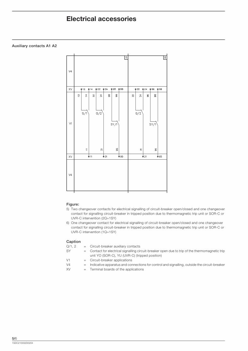
5/61SDC210032D0204
Electrical accessories
Auxiliary contacts A1 A2
Figure: 5) Two changeover contacts for electrical signalling of circuit-breaker open/closed and one changeover
contact for signalling circuit-breaker in tripped position due to thermomagnetic trip unit or SOR-C or UVR-C intervention (2Q+1SY)
6) One changeover contact for electrical signalling of circuit-breaker open/closed and one changeover contact for signalling circuit-breaker in tripped position due to thermomagnetic trip unit or SOR-C or UVR-C intervention (1Q+1SY)
CaptionQ/1, 2 = Circuit-breaker auxiliary contactsSY = Contact for electrical signalling circuit-breaker open due to trip of the thermomagnetic trip
unit YO (SOR-C), YU (UVR-C) (tripped position) V1 = Circuit-breaker applicationsV4 = Indicative apparatus and connections for control and signalling, outside the circuit-breakerXV = Terminal boards of the applications
Formula_05_schemi.indd 6 21/02/2011 9.41.20

5/71SDC210032D0204
Auxiliary contacts A3
Figure: 5) Three changeover contacts for electrical signalling of circuit-breaker open/closed and one changeo-Three changeover contacts for electrical signalling of circuit-breaker open/closed and one changeo-
ver contact for signalling circuit-breaker in tripped position due to thermomagnetic trip unit or SOR-C or UVR-C intervention (3Q+1SY)
6) One changeover contact for electrical signalling of circuit-breaker open/closed and one changeover contact for signalling circuit-breaker in tripped position due to thermomagnetic trip unit or SOR-C or UVR-C intervention (1Q+1SY)
CaptionQ/1, 2, 3 = Circuit-breaker auxiliary contactsSY = Contact for electrical signalling circuit-breaker open due to trip of the thermomagnetic trip
unit YO (SOR-C), YU (UVR-C) (tripped position) V1 = Circuit-breaker applicationsV4 = Indicative apparatus and connections for control and signalling, outside the circuit-breakerXV = Terminal boards of the applicationsX2, X7 = Connectors for the circuit-breaker auxiliary circuits
Formula_05_schemi.indd 7 21/02/2011 9.41.21


6/11SDC210032D0204
Overall dimensions
Content
FORMULA A1
Circuit-breaker and terminals .................................................................................................. 6/2
Accessories ............................................................................................................................ 6/8
FORMULA A2
Circuit-breaker and terminals .................................................................................................. 6/9
Accessories ............................................................................................................................ 6/15
FORMULA A3
Circuit-breaker and terminals .................................................................................................. 6/16
Accessories ............................................................................................................................ 6/20
FORMULA Link
FORMULA Link 250A ............................................................................................................. 6/22
FORMULA Link 400A ............................................................................................................. 6/23
FORMULA Link 630A ............................................................................................................. 6/24
FORMULA Link 800A ............................................................................................................. 6/25
Distances to be respected ................................................................................................... 6/26
Formula_06_dimensioni.indd 1 21/02/2011 9.42.12
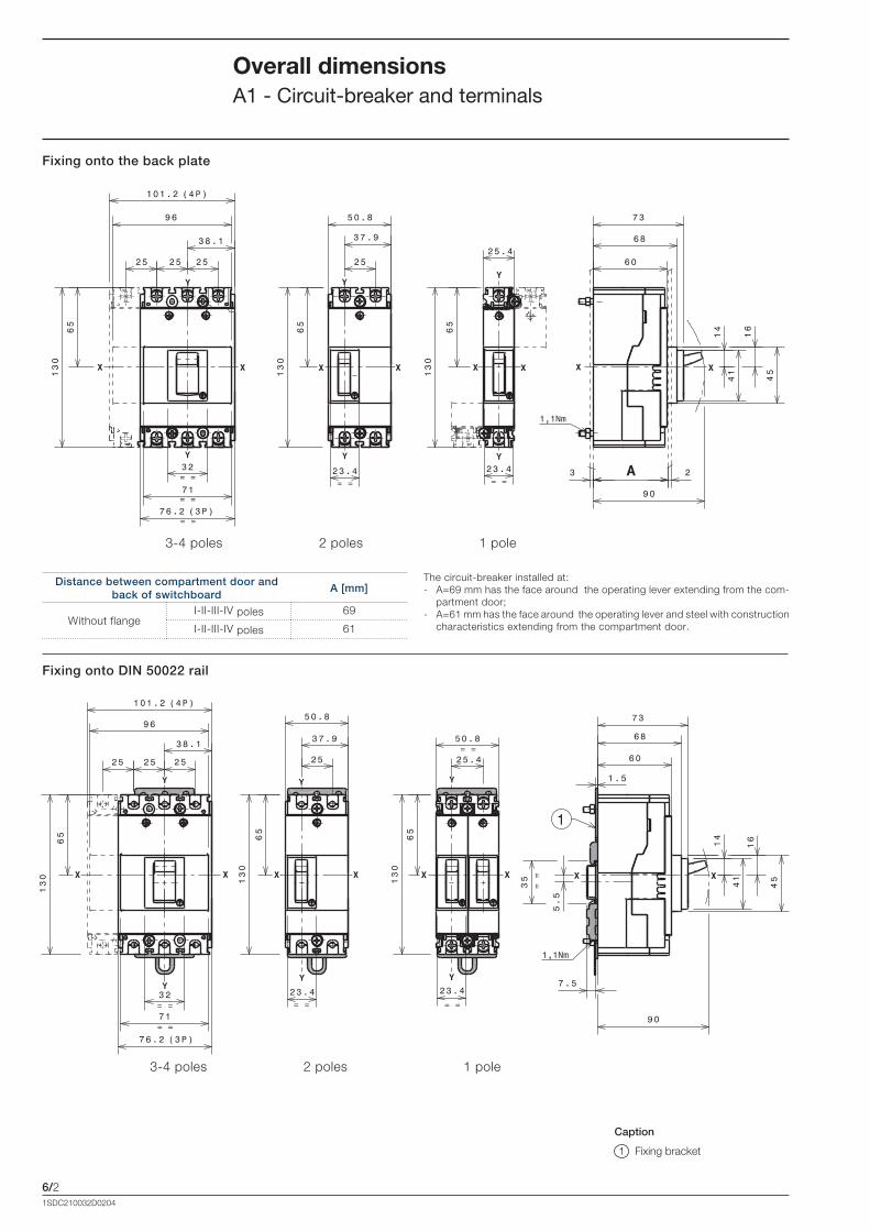
6/21SDC210032D0204
Overall dimensionsA1 - Circuit-breaker and terminals
Fixing onto the back plate
Fixing onto DIN 50022 rail
Distance between compartment door and back of switchboard
A [mm]
Without flangeI-II-III-IV poles 69
I-II-III-IV poles 61
Caption
1 Fixing bracket
3-4 poles 2 poles 1 pole
3-4 poles 2 poles 1 pole
The circuit-breaker installed at:- A=69 mm has the face around the operating lever extending from the com-
partment door;- A=61 mm has the face around the operating lever and steel with construction
characteristics extending from the compartment door.
Formula_06_dimensioni.indd 2 21/02/2011 9.42.12

6/31SDC210032D0204
Drilling templates for support sheet
Drilling templates for compartment door
1-3-4 poles 2 poles
A = 69mm1-2 poles
A = 69mm3-4 poles
A = 61mm1 pole
A = 61mm2 poles
A = 61mm3 poles
A = 61mm4 poles
Formula_06_dimensioni.indd 3 21/02/2011 9.42.13

6/41SDC210032D0204
F Terminals
EF Terminals
Caption
1 50mm insulating barriers between the terminals (compulsory) not supplied with EF terminals kit, but with the circuit-breaker in base version
2 Top terminal covers with IP40 degree of protection (on request)
3 Front extended terminals
Caption
1 50mm insulating barriers between the terminals (compulsory) supplied
Overall dimensionsA1 - Circuit-breaker and terminals
3-4 poles 2 poles 1 pole
3-4 poles 2 poles 1 pole
Formula_06_dimensioni.indd 4 21/02/2011 9.42.14

6/51SDC210032D0204
Caption
1 Front extended spread terminals
2 100mm insulating barriers between the terminals (compulsory) supplied
4 poles 3 poles 2 poles
ES Terminals
Formula_06_dimensioni.indd 5 21/02/2011 9.42.14

6/61SDC210032D0204
FCCuAl 1x25...50mm2 Terminals
Overall dimensionsA1 - Circuit-breaker and terminals
Caption
3 Bottom terminal covers with IP40 degree of protection (compulsory)
4 FCCuAl 50mm2 terminals
6 50mm insulating barriers between the terminals (compulsory) not supplied with FCCuAl terminals kit, but with the circuit-breaker in base version
7 Compartment door drilling template and fixing insulation (provided by customer)
8 Compulsory internal 1 pole - 2 pole insulation plates
(provided by customer)
3-4 poles 3-4 poles
1-2 poles 1-2 poles
1-2 poles 1-2 poles
A [mm] B [mm] C [mm]
Without flange
69 33 66 1 POLE
69 58 91 2 POLES
61* 33 66 1 POLE
61* 58 91 2 POLES
* Distance only possible with insulation plate max 1 mm thick
Formula_06_dimensioni.indd 6 21/02/2011 9.42.15

6/71SDC210032D0204
FCCuAl 1x1...25mm2 Terminals
Caption
3 Bottom terminal covers with IP40 degree of protection (compulsory)
5 FCCuAl 25mm2 terminals
6 50mm insulating barriers between the terminals (compulsory) not supplied with FCCuAl terminals kit, but with the circuit-breaker in base version
7 Compartment door drilling template and fixing insulation (provided by customer)
8 Compulsory internal 1 pole - 2 pole insulation plates
(provided by customer)
3-4 poles 3-4 poles
1-2 poles 1-2 poles
1-2 poles 1-2 poles
A [mm] B [mm] C [mm]
Without flange
69 33 66 1 POLE
69 58 91 2 POLES
61* 33 66 1 POLE
61* 58 91 2 POLES
* Distance only possible with insulation plate max 1 mm thick
Formula_06_dimensioni.indd 7 21/02/2011 9.42.16
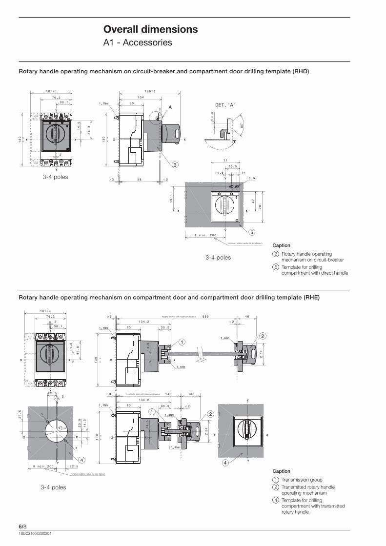
6/81SDC210032D0204
Overall dimensionsA1 - Accessories
Rotary handle operating mechanism on circuit-breaker and compartment door drilling template (RHD)
Rotary handle operating mechanism on compartment door and compartment door drilling template (RHE)
Caption
3 Rotary handle operating mechanism on circuit-breaker
5 Template for drilling compartment with direct handle
Caption
1 Transmission group
2 Transmitted rotary handle operating mechanism
4 Template for drilling compartment with transmitted rotary handle
3-4 poles
3-4 poles
heights for door with maximum distance
heights for door with maximum distance
minimum rotation radius for door fulcrum
3-4 poles
minimum rotation radius for door fulcrum
Formula_06_dimensioni.indd 8 21/02/2011 9.42.17
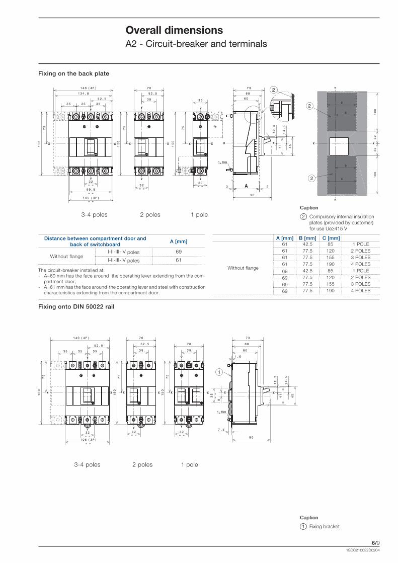
6/91SDC210032D0204
Overall dimensionsA2 - Circuit-breaker and terminals
Fixing on the back plate
Fixing onto DIN 50022 rail
Distance between compartment door and back of switchboard
A [mm]
Without flangeI-II-III-IV poles 69
I-II-III-IV poles 61
Caption
1 Fixing bracket
3-4 poles 2 poles 1 pole
3-4 poles 2 poles 1 pole
The circuit-breaker installed at:- A=69 mm has the face around the operating lever extending from the com-
partment door;- A=61 mm has the face around the operating lever and steel with construction
characteristics extending from the compartment door.
A [mm] B [mm] C [mm]
Without flange
61 42.5 85 1 POLE61 77.5 120 2 POLES61 77.5 155 3 POLES61 77.5 190 4 POLES
69 42.5 85 1 POLE
69 77.5 120 2 POLES
69 77.5 155 3 POLES
69 77.5 190 4 POLES
Caption
2 Compulsory internal insulation plates (provided by customer) for use Ue�415 V
Formula_06_dimensioni.indd 9 21/02/2011 9.42.18

6/101SDC210032D0204
Drilling templates for support sheet
Compartment door drilling templates
Overall dimensionsA2 - Circuit-breaker and terminals
A = 69mm1-2-3-4 poles
A = 61mm1 pole
A = 61mm2 poles
A = 61mm3 poles
A = 61mm4 poles
1-3-4 poles 2 poles
Formula_06_dimensioni.indd 10 21/02/2011 9.42.18

6/11
8
8
8
1SDC210032D0204
F Terminals
EF Terminals
Caption
1 80mm insulating barriers between the terminals (compulsory) not supplied with EF terminals kit, but with the circuit-breaker in base version
2 Top terminal covers with IP40 degree of protection (on request)
3 Front extended terminals
Caption
1 80mm insulating barriers between the terminals (compulsory) supplied
2-3-4 poles 1 poles
3-4 poles
2 poles 1 pole
Formula_06_dimensioni.indd 11 21/02/2011 9.42.19

6/121SDC210032D0204
ES Terminals
Caption
1 Front extended spread terminals
2 100mm insulating barriers between the terminals (compulsory) supplied
Overall dimensionsA2 - Circuit-breaker and terminals
4 poles 3 poles 2 poles
Formula_06_dimensioni.indd 12 21/02/2011 9.42.20

6/131SDC210032D0204
FCCuAl 1x120...185mm2 Terminals
Caption
3 Bottom terminal covers with IP40 degree of protection (compulsory)
5 Terminals FCCuAl 185mm2
6 80mm insulating barriers between the terminals (compulsory) not supplied with FCCuAl terminals kit, but with the circuit-breaker in base version
7 Compartment door drilling template and fixing insulation (provided by customer) 1 pole - 2 poles
8 Compulsory internal insulation plates (provided by customer) max 1mm thick
3-4 poles 3-4 poles
1 poles 2 poles 1-2 poles
1-2 poles 1-2 poles
A [mm] B [mm] C [mm]
Without flange
69 42.5 85 1 POLE
69 77.5 120 2 POLES
61 42.5 85 1 POLE
61 77.5 120 2 POLES
If terminals are mounted on top of circuit-breaker, Icu=50% and Ics=Icu.
Formula_06_dimensioni.indd 13 21/02/2011 9.42.20
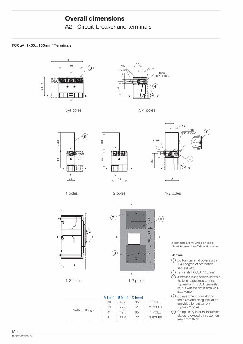
6/141SDC210032D0204
FCCuAl 1x50...150mm2 Terminals
Caption
3 Bottom terminal covers with IP40 degree of protection (compulsory)
4 Terminals FCCuAl 150mm2
6 80mm insulating barriers between the terminals (compulsory) not supplied with FCCuAl terminals kit, but with the circuit-breaker in base version
7 Compartment door drilling template and fixing insulation (provided by customer) 1 pole - 2 poles
8 Compulsory internal insulation plates (provided by customer)max 1mm thick
Overall dimensionsA2 - Circuit-breaker and terminals
3-4 poles 3-4 poles
1 poles 2 poles 1-2 poles
1-2 poles 1-2 poles
A [mm] B [mm] C [mm]
Without flange
69 42.5 85 1 POLE
69 77.5 120 2 POLES
61 42.5 85 1 POLE
61 77.5 120 2 POLES
If terminals are mounted on top of circuit-breaker, Icu=50% and Ics=Icu.
Formula_06_dimensioni.indd 14 21/02/2011 9.42.21
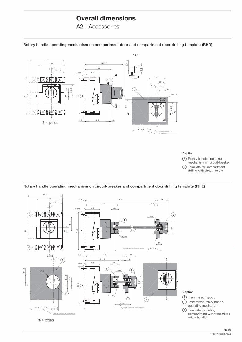
6/151SDC210032D0204
Overall dimensionsA2 - Accessories
Rotary handle operating mechanism on compartment door and compartment door drilling template (RHD)
Rotary handle operating mechanism on circuit-breaker and compartment door drilling template (RHE)
Caption
1 Transmission group
2 Transmitted rotary handle operating mechanism
4 Template for drilling compartment with transmitted rotary handle
Caption
3 Rotary handle operating mechanism on circuit-breaker
5 Template for compartment drilling with direct handle
3-4 poles
heights for door with maximum distance
minimum rotation radius for door fulcrum
heights for door with maximum distance
3-4 poles
minimum rotation radius for door fulcrum
Formula_06_dimensioni.indd 15 21/02/2011 9.42.22
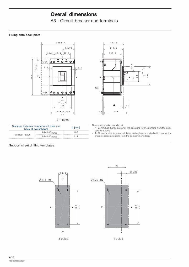
6/161SDC210032D0204
Overall dimensionsA3 - Circuit-breaker and terminals
Fixing onto back plate
Support sheet drilling templates
3-4 poles
3 poles 4 poles
Distance between compartment door and back of switchboard
A [mm]
Without flangeI-II-III-IV poles 105
I-II-III-IV poles 114
The circuit-breaker installed at:- A=69 mm has the face around the operating lever extending from the com-
partment door;- A=61 mm has the face around the operating lever and steel with construction
characteristics extending from the compartment door.
Formula_06_dimensioni.indd 16 21/02/2011 9.42.23
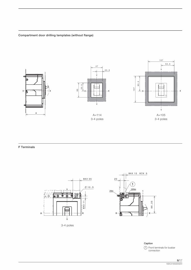
6/171SDC210032D0204
Compartment door drilling templates (without flange)
F Terminals
Caption
1 Front terminals for busbar connection
A=1143-4 poles
A=1053-4 poles
3-4 poles
Formula_06_dimensioni.indd 17 21/02/2011 9.42.23
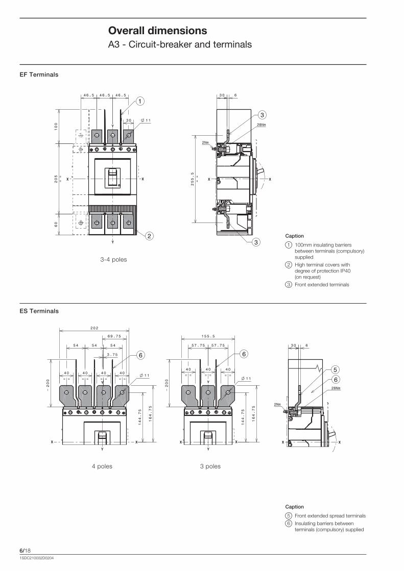
6/181SDC210032D0204
Overall dimensionsA3 - Circuit-breaker and terminals
EF Terminals
ES Terminals
Caption
1 100mm insulating barriers between terminals (compulsory) supplied
2 High terminal covers with degree of protection IP40 (on request)
3 Front extended terminals
3-4 poles
4 poles 3 poles
Caption
5 Front extended spread terminals
6 Insulating barriers between terminals (compulsory) supplied
Formula_06_dimensioni.indd 18 21/02/2011 9.42.23

6/191SDC210032D0204
FCCuAl 1x185...300mm2 Terminals
Caption
1 Front terminals for busbar connection 300mm2 CuAl
3-4 poles
FCCuAl 2x95...240mm2 Terminals
Caption
1 60mm high terminal covers (compulsory) supplied
3-4 poles
Formula_06_dimensioni.indd 19 21/02/2011 9.42.24

6/201SDC210032D0204
Overall dimensionsA3 - Accessories
Rotary handle operating mechanism on circuit-breaker + Compartment door drilling template (RHD)
Rotary handle operating mechanism on compartment door + Compartment door drilling template (RHE)
Caption
3 Rotary handle operating mechanism on circuit-breaker
5 Template for drilling compartment with direct handle
Caption
1 Transmission unit
2 Rotary transmitted handle operating machanism
3 Rotary handle operating mechanism on circuit-breaker
4 Template for drilling compartment with transmitted rotary handle
5 Drilling for door template with direct handle
3-4 poles
heights for door with maximum distance
heights for door with maximum distance
minimum rotation radius for door fulcrum
3-4 poles
3-4 poles
Formula_06_dimensioni.indd 20 21/02/2011 9.42.24

6/211SDC210032D0204
Front for lock operating mechanism (FLD)
3-4 poles
Formula_06_dimensioni.indd 21 21/02/2011 9.42.25
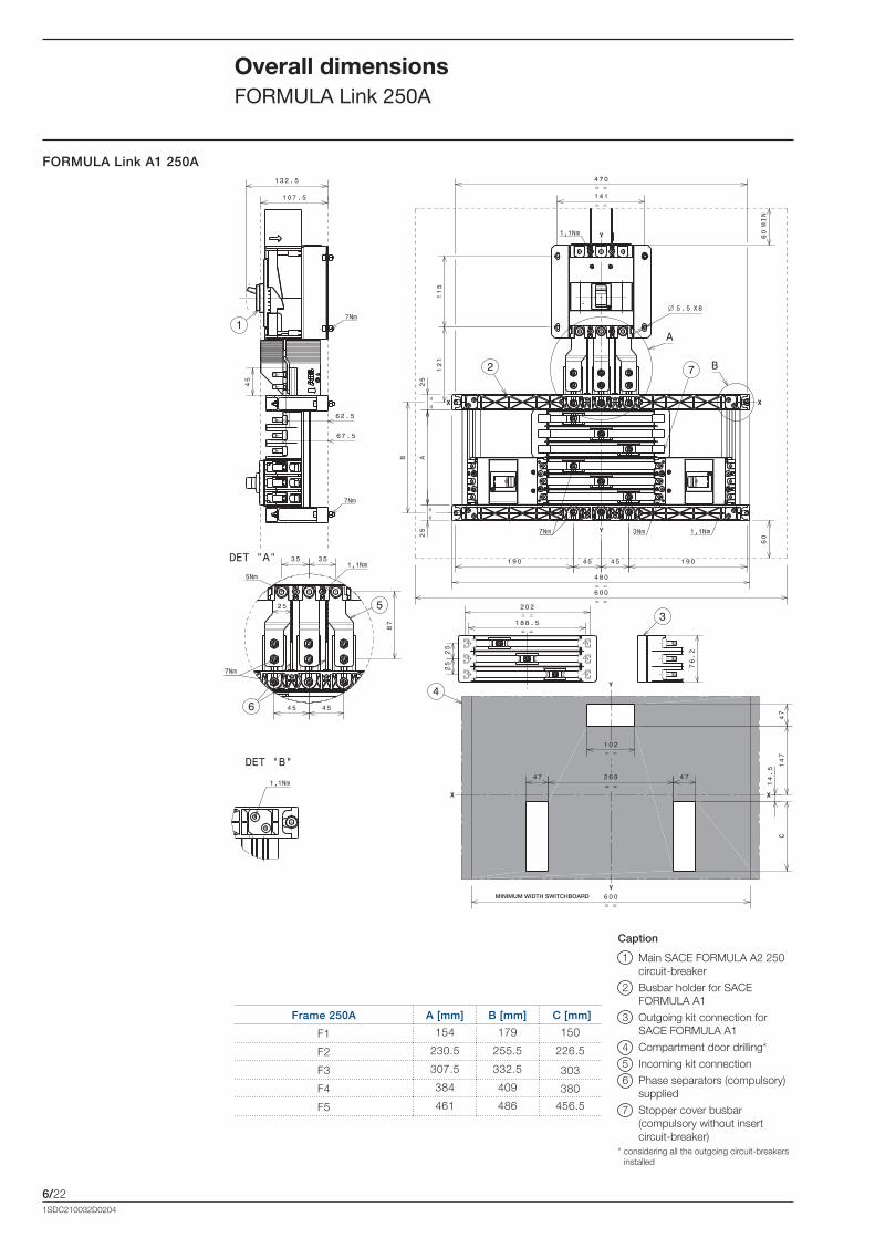
6/22
FORMULA Link A1 250A
1SDC210032D0204
Overall dimensionsFORMULA Link 250A
Caption
1 Main SACE FORMULA A2 250 circuit-breaker
2 Busbar holder for SACE FORMULA A1
3 Outgoing kit connection for SACE FORMULA A1
4 Compartment door drilling*
5 Incoming kit connection
6 Phase separators (compulsory) supplied
7 Stopper cover busbar (compulsory without insert circuit-breaker)* considering all the outgoing circuit-breakers
installed
Frame 250A A [mm] B [mm] C [mm]
F1 154 179 150
F2 230.5 255.5 226.5
F3 307.5 332.5 303
F4 384 409 380
F5 461 486 456.5
MINIMUM WIDTH SWITCHBOARD
Formula_06_dimensioni.indd 22 21/02/2011 9.42.25

6/23
FORMULA Link A1-A2 400A
1SDC210032D0204
Overall dimensionsFORMULA Link 400A
With A1 only With A1 and A2, or A2 only
D 600 800
Frame 400A A [mm] B [mm] C [mm]
F1 154 179 150
F2 230.5 255.5 226.5
F3 307.5 332.5 303
F4 384 409 380
F5 461 486 456.5
MINIMUM WIDTH SWITCHBOARD
Caption
1 Main SACE FORMULA A3 400A circuit-breaker 2 Busbar holder 3 Outgoing kit connection SACE FORMULA A1 4 Outgoing kit connection SACE FORMULA A2 5 Compartment door drilling* 6 Incoming kit connection 7 Phase separators (compulsory) supplied 8 Tightening torque: 3 Nm for SACE FORMULA A1 9 Tightening torque: 5 Nm for SACE FORMULA A2 10 Stopper cover busbar (compulsory without insert circuit-breaker)* considering all the outgoing circuit-breakers
installed
Formula_06_dimensioni.indd 23 21/02/2011 9.42.26

6/24
FORMULA Link A1-A2 630A
1SDC210032D0204
Overall dimensionsFORMULA Link 630A
With A1 only With A1 and A2, or A2 only
D 600 800
Frame 630A A [mm] B [mm] C [mm]
F1 154 179 150
F2 230.5 255.5 226.5
F3 307.5 332.5 303
F4 384 409 380
F5 461 486 456.5
MINIMUM WIDTH SWITCHBOARD
Caption
1 Main SACE Tmax T6 630A circuit-breaker 2 Busbar holder 3 Outgoing kit connection SACE FORMULA A1 4 Outgoing kit connection SACE FORMULA A2 5 Compartment door drilling* 6 Incoming kit connection 7 Phase separators (compulsory) supplied 8 Tightening torque: 3 Nm for SACE FORMULA A1 9 Tightening torque: 5 Nm for SACE FORMULA A2 10 Stopper cover busbar (compulsory without insert circuit-breaker)* considering all the outgoing circuit-breakers
installed
Formula_06_dimensioni.indd 24 21/02/2011 9.42.27
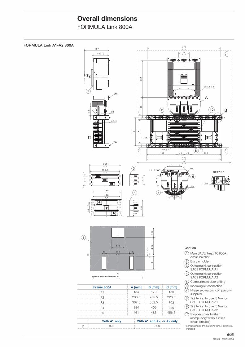
6/25
FORMULA Link A1-A2 800A
1SDC210032D0204
Overall dimensionsFORMULA Link 800A
With A1 only With A1 and A2, or A2 only
D 800 800
Frame 800A A [mm] B [mm] C [mm]
F1 154 179 150
F2 230.5 255.5 226.5
F3 307.5 332.5 303
F4 384 409 380
F5 461 486 456.5
MINIMUM WIDTH SWITCHBOARD
Caption
1 Main SACE Tmax T6 800A circuit-breaker 2 Busbar holder 3 Outgoing kit connection SACE FORMULA A1 4 Outgoing kit connection SACE FORMULA A2 5 Compartment door drilling* 6 Incoming kit connection 7 Phase separators (compulsory) supplied 8 Tightening torque: 3 Nm for SACE FORMULA A1 9 Tightening torque: 5 Nm for SACE FORMULA A2 10 Stopper cover busbar (compulsory without insert circuit-breaker)* considering all the outgoing circuit-breakers
installed
Formula_06_dimensioni.indd 25 21/02/2011 9.42.28

6/261SDC210032D0204
Overall dimensionsDistances to be respected
Insulation distances to be respected for installation in cubicles
Ue<415VA
[mm]
B
[mm]
C
[mm]
A1 45 20 35
A2 60 25 60
A3 30 25 25
Minimum centre distance between two circuit-breakers side by side
Circuit-breaker width[mm]
Centre distance I[mm]
1 pole
2 poles
3 poles
4 poles
1 pole
2 poles
3 poles
4 poles
A1 25.4 50.8 76.2 101.2 25.4* 50.8* 76.2* 101.2*
A2 36 70 105 140 36* 70* 105* 140*
A3 - - 140 184 - - 140** 184**
* For 440V<Ue<550V I 3p=180mm and I 4p=224mm** With separator to be requested apart and to be inserted between twocircuit-breakers side by side.
Minimum centre distance between two stacked circuit-breakers
H[mm]
A1 80
A2 100 (Ue<415V) 260 (Ue�415V)
A3 160
Caption
1 Connection not insulated
2 Insulated cable
3 Cable terminal
Ue�440VA
[mm]
B
[mm]
C
[mm]
A1 45 20 35
A2 180 25 60
A3 60 25 25
Formula_06_dimensioni.indd 26 21/02/2011 9.42.29
7/11SDC210032D0204
Glossary
Content
G1 - Circuit-breaker ............................................................................................................ 7/2
G2 - Performance Parameters ........................................................................................... 7/4
G3 - Releases and Protections ........................................................................................... 7/6
G4 - Regulations and Standards ........................................................................................ 7/7
Formula_07_glossario.indd 1 21/02/2011 9.43.10

7/21SDC210032D0204
G1.1 Circuit-breakerA mechanical switching device, capable of making, carrying and breaking currents under normal circuit conditions and also making, carrying for a specified time and breaking currents under specified abnormal circuit conditions such as short-circuit.
G1.2 Protection degree (IP)The IP protection degree indicates the level of protection for apparatus against contact with live parts and penetration of liquids and solid foreign bodies.
G1.3 Rate of contact wearPercentage of contacts wear, indicatively gives the state of durability of the circuit-breaker contacts.
G1.4 Double insulationA double insulation between the live power parts and the front parts of the apparatus where the operator works during normal plant service is present in all the circuit-breakers, so as to eliminate the risk of contacts with live parts. The seat of each electrical acces-sory is completely segregated from the power circuit. In particular, the operating unit is completely insulated in relation to the voltage circuits. Furthermore, both between the internal live parts and in the area of the connection terminals, the circuit-breaker has redundant insulation. In fact, the distances between the connection terminals are greater than those required by the IEC Standards and conform to what is prescribed by the American UL 489 Standard.
G1.5 Positive operationThe operating lever always indicates the actual position of the mobile circuit-breaker contacts: • red line (I): Closed position;• green line (O): Open position; • yellow-green line: Trip Position, open due to release trip or test pushbotton.The indications are precise and reliable, in conformity with what is prescribed by the IEC 60073 and IEC 60417-2 Standards. Tripping of the releases automatically opens the mobile contacts and makes the lever move into the Trip position: to reclose the circuit-breaker it must be reset, by pushing the operating lever from the trip position to the Open position. The operating mechanism of the circuit-breaker has free trip, independent of the pres-sure on the lever and of the speed of the operation. From this position it is possible to close the circuit-breaker.
G1.6 Isolation behaviourCharacteristic of a mechanical operating device which, in the open and trip position, carries out a disconnection function and guarantees an insulation distance (distance between fixed and mobile contacts) sufficient to guarantee safety.
G1.7 Electromagnetic compatibility In conformity with the IEC 60947-2 Standards (Annex B + Annex F, European
Directive No. 89/336) relative to electromagnetic compatibility EMC, the circuit-breakers used with electronic trip units and residual current releases are guaranteed to function in the presence of disturbances caused by: • electromagnetic apparatus;• atmospheric disturbances which flow through power networks;• interferences from radio waves;• discharges of electrical type. Furthermore, the circuit-breakers does not generate disturbances to other electronic apparatus near the place of installation.
GlossaryG1 - Circuit-breaker
Formula_07_glossario.indd 2 21/02/2011 9.43.10
7/31SDC210032D0204
G1.8 Tropicalization All the circuit-breakers can be used in the most severe environmental conditions
defined by the following standards: • IEC 60721-2-1 (climograph 8);• IEC 60068-2-30;• IEC 60068-2-2; • IEC 60068-2-52.Tropicalization is guaranteed by: • synthetic resin insulating boxes reinforced with fibreglass;• anti-corrosion treatment of the main metallic parts;• galvanisation Fe/Zn (UNI ISO 2081), protected by a conversion layer without hexavalent
chromium (in conformity with the ROHS) with the same corrosion resistance guaranteed by ISO 4520 class 2c;
• application of anti-condensation protection for electronic overcurrent releases and relative accessories.
Formula_07_glossario.indd 3 21/02/2011 9.43.10
7/41SDC210032D0204
G2.1 Frame sizeA term designating a group of circuit-breakers, the external physical dimensions of which are common to a range of current ratings (considering the same number of poles). Frame size is expressed in amperes corresponding to the highest current rating of the group.
G2.2 Rated current (In)For the circuit-breakers the rated current represent the current which the circuit-breaker can carry in uninterrupted duty.
G2.3 Rated service voltage (Ue)The a rated service voltage of an equipment is the voltage value which, together with the rated service current, determines the use of the equipment and which the applicable tests and the utilization category refer to.
G2.4 Rated insulation voltage (Ui)The rated insulation voltage of an equipment is the value of voltage to which dielectric tests and the surface creepage distances are referred. In no case the maximum value of the rated operating voltage shall exceed that of the rated insulation voltage.
G2.5 Rated impulse withstand voltage (Uimp)The peak value of an impulse voltage of prescribed form and polarity which the equip-ment is capable of withstanding without failure under specified test conditions and to which the clearance values are referred.
G2.6 Rated ultimate short-circuit breaking capacity (Icu)The rated ultimate short-circuit breaking capacity of a circuit-breaker is the maximum short-circuit current value which the circuit-breaker can break twice (in accordance with the cycle O – t – CO), at the corresponding rated operational voltage. After the indicated sequence the circuit-breaker is not required to carry its rated current.
G2.7 Rated service short-circuit breaking capacity (Ics)The rated service short-circuit breaking capacity of a circuit-breaker is the maximum short-circuit current value which the circuit-breaker can break three times in accord-ance with a sequence of opening, pause and closing operations (O - t - CO - t – CO) at a defined rated service voltage (Ue) and at a defined power factor. After the indicated sequence the circuit-breaker is required to carry its rated current.
G2.8 Rated short-circuit making capacity (Icm):The rated short-circuit making capacity of an equipment is the value, stated by the manufacturer, at the rated service voltage, at rated frequency, and at a specified power factor for alternating current or time constant direct current. It is expressed as the maximum peak value of the prospective current under specified conditions.
GlossaryG2 - Performance Parameters
Formula_07_glossario.indd 4 21/02/2011 9.43.10

7/51SDC210032D0204
Kind of current Category Typical application
Alternating current
AC-12Control of restistive loads and solid state loads with isolation by optocouplers
AC-13 Control of solid state loads with transformer isolation
AC-14 Control of small electromagnetic loads (�72VA)
AC-15 Control of electromagnetic loads (>72VA)
Direct current
DC-12Control of restistive loads and solid state loads with isolation by optocouplers
DC-13 Control of electromagnets
DC-14Control of small electromagnetic loads having economy resis-tors in circuit
G2.9 Utilization category of circuit-breakersThe utilization category of a circuit-breaker must be established according to whether or not it is specifically intended for selectivity by means of an intentional time delay, with respect to other circuit-breaker in series on the load side, under short-circuit conditions. Two category of use can be specified:Category A - Circuit-breakers not specifically intended for selectivity under short-circuit conditions with respect to other short-circuit protective devices in series on the load side, i.e. without a short-time withstand current rating.Category B - Circuit-breakers specifically intended for selectivity under short-circuit conditions with respect to other protection devices in series on the load side, i.e. with intentional time delay (which can be adjustable) applicable under short-circuit condi-tions. These circuit-breakers have specified short-time withstand current rating (Icw).A circuit-breaker is classified in category B if its Icw value is higher than:• between 12xIn and 5kA, whichever is the greatest, for In�2500A;• 30 kA, for In>2500A.
G2.10 Mechanical lifeThe mechanical durability (or mechanical life) of an apparatus is expressed by the number of no-load operating cycles (each operating cycle consists of one closing and opening operation) which can be carried out by the apparatus before it becomes necessary to service or replace any of its mechanical parts (however, normal maintenance is permitted).
G2.11 Electrical life Electrical durability (or electrical life) of an apparatus is expressed by the number of on-load operating cycles and the resistance of the contacts to electrical wear under the conditions specified in the relevant Product Standard.
G2.12 Dissipated powerIs the energy loss caused by the Joule effect due to the electrical resistance of the circuit-breaker poles. The energy lost is dissipated in the form of heat.
G2.13 Utilization categories of the auxiliary contacts The utilization categories given in the table are considered standardised. [CEI EN 60947-5-1]
Formula_07_glossario.indd 5 21/02/2011 9.43.10

7/61SDC210032D0204
GlossaryG3 - Releases and Protections
G3.1 Trip unitDevice, mechanically connected to a mechanical operating mechanism, which release the latching parts and allows the opening or closing of the operating device.
G3.2 Thermomagnetic trip unitThermomagnetic trip units use a bimetal and an electromagnet to detect overloads and short-circuits. They are suitable for protection of both alternating and direct cur-rent networks.
G3.3 Electronic trip unitTrip units connected to current transformers (three or four according to the number of conductors to be protected) positioned inside the circuit-breaker, which carry out the double function of supplying the power supply needed for correct operation of the release (self-supply) and of detecting the value of the current which flows through the live conductors. However, they are only compatible with alternating current networks.The signal coming from the transformers and from the Rogowsky coils is appropri-ately processed by the electronics (microprocessor) which compares it with the set thresholds. When the signal exceeds the thresholds, the trip of the circuit-breaker is operated through an opening solenoid which acts directly on the circuit-breaker oper-ating mechanism unit.In the case of an auxiliary power supply in addition to self-supply, the voltage must have a value of 24V DC ± 20%.
G3.4 Thermal Protection L
Protection against overloads with long inverse time delay trip.
G3.5 Magnetic Protection I Protection against short-circuit with instantaneous trip.
Formula_07_glossario.indd 6 21/02/2011 9.43.10
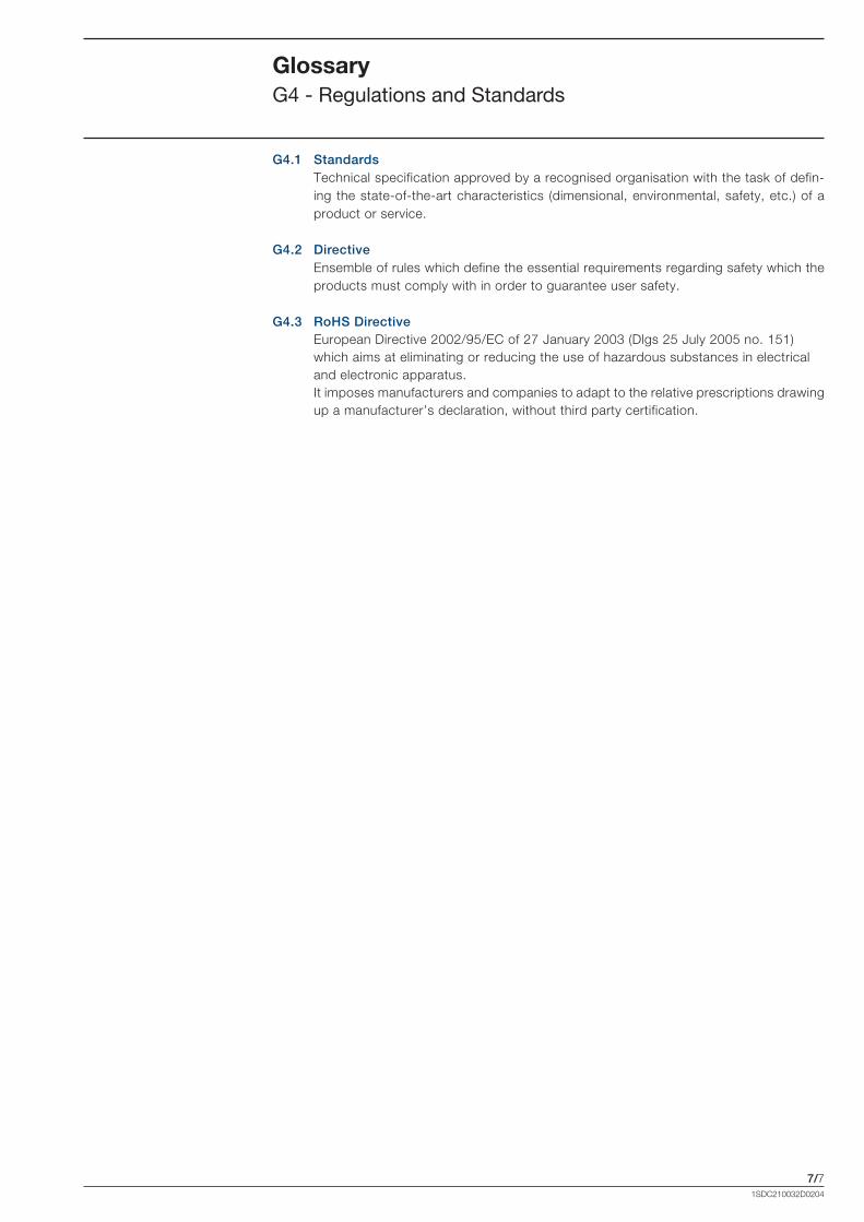
7/71SDC210032D0204
GlossaryG4 - Regulations and Standards
G4.1 StandardsTechnical specification approved by a recognised organisation with the task of defin-ing the state-of-the-art characteristics (dimensional, environmental, safety, etc.) of a product or service.
G4.2 DirectiveEnsemble of rules which define the essential requirements regarding safety which the products must comply with in order to guarantee user safety.
G4.3 RoHS Directive European Directive 2002/95/EC of 27 January 2003 (Dlgs 25 July 2005 no. 151)
which aims at eliminating or reducing the use of hazardous substances in electrical and electronic apparatus.It imposes manufacturers and companies to adapt to the relative prescriptions drawing up a manufacturer’s declaration, without third party certification.
Formula_07_glossario.indd 7 21/02/2011 9.43.10
1SD
C21
0032
D02
04 -
03.
2011
- 2
.000
Contact us
ABB SACEA division of ABB S.p.A.L.V. BreakersVia Baioni, 3524123 BergamoPhone: +39 035 395.111Fax: +39 035 395.306-433
www.abb.com
The data and illustrations are not binding. We reserve the right to modify the contents of this document on the basis of technical development of the products, without prior notice.
Copyright 2011 ABB.All rights reserved.
Top Related