


Languages
Pages
Legal

The International Desalination Association World Congress on Desalination and Water Reuse 2013 / Tianjin, China
REF: IDAWC/TIAN13-204
RO MEMBRANE CLEANING, PAST, PRESENT, FUTURE – INNOVATIONS
FOR IMPROVING RO PLANT OPERATING EFFICIENCY
Authors: S. P. Chesters, M.W. Armstrong, M. Fazel, R. Wilson, D.A. Golding
Presenter: Stephen P. Chesters
Managing Director, Genesys International Ltd, UK
Abstract
This paper reviews current thinking on reverse osmosis (RO) membrane cleaning. It challenges
preconceptions and describes novel approaches for the removal of foulants and scale deposits from
membrane surfaces. Applying membrane cleaning early in the fouling process before deposits can
become compressed is advocated. Waiting until membranes are so fouled that they have a drop in
performance of 10-15% as traditionally recommended makes deposits significantly more difficult to
remove. The concept of autopsying and cleaning early to reduce underlying fouling rates is explained.
The use of recent innovative methods for membrane cleaning is reviewed. New approaches developed
by the authors are described and the mechanisms of enhanced cleaning explained. These include use of a
cleaning suspension of bubbles, effervescent and high ionic strength cleaners. Enhanced cleaning is
observed as a result of agitation of deposits on the membrane surface by different mechanisms which
assist foulant removal. Small bubbles are generated during the cleaning process by a combination of
different chemical and physical methods. The use of high ionic strength cleaners creates a small flow of
permeate across the membrane to the feed side during the soaking period of cleaning. This flow is
sufficient to help dislodge foulants on the membrane surface. The authors describe and explain the
unique mechanisms of cleaning. Methodology and results of laboratory and pilot plant tests are
summarised demonstrating significant improvement in membrane cleaning. This simple technique could
easily be applied to existing RO plant restoring efficient RO plant operation.
The International Desalination Association (IDA)
World Congress on Desalination and Water Reuse
REF: IDAWC/TIAN13-204 -- 2 --
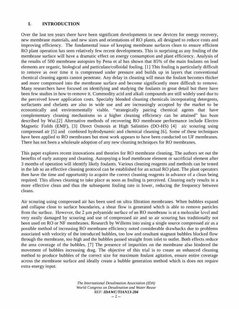
I. INTRODUCTION
Over the last ten years there have been significant developments in new devices for energy recovery,
new membrane materials, and new sizes and orientations of RO plants, all designed to reduce costs and
improving efficiency. The fundamental issue of keeping membrane surfaces clean to ensure efficient
RO plant operation has seen relatively few recent developments. This is surprising as any fouling of the
membrane surface will have a dramatic effect on energy consumption and plant efficiency. Analysis of
the results of 500 membrane autopsies by Pena et al has shown that 85% of the main foulants on lead
elements are organic, biological and particulate/colloidal fouling. [1] This fouling is particularly difficult
to remove as over time it is compressed under pressure and builds up in layers that conventional
chemical cleaning agents cannot penetrate. Any delay in cleaning will mean the foulant becomes thicker
and more compressed into the membrane surface and become significantly more difficult to remove.
Many researchers have focused on identifying and studying the foulants in great detail but there have
been few studies in how to remove it. Commodity acid and alkali compounds are still widely used due to
the perceived lower application costs. Specialty blended cleaning chemicals incorporating detergents,
surfactants and chelants are also in wide use and are increasingly accepted by the market to be
economically and environmentally viable. “strategically pairing chemical agents that have
complementary cleaning mechanisms so a higher cleaning efficiency can be attained” has been
described by Wui.[2] Alternative methods of recovering RO membrane performance include Electro
Magnetic Fields (EMF), [3] Direct Osmosis at High Salinities (DO-HS) [4] air scouring using
compressed air [5] and combined hydrodynamic and chemical cleaning [6]. Some of these techniques
have been applied to RO membranes but most work appears to have been conducted on UF membranes.
There has not been a wholesale adoption of any new cleaning techniques for RO membranes.
This paper explores recent innovations and theories for RO membrane cleaning. The authors set out the
benefits of early autopsy and cleaning. Autopsying a lead membrane element or sacrificial element after
3 months of operation will identify likely foulants. Various cleaning reagents and methods can be tested
in the lab so an effective cleaning protocol can be established for an actual RO plant. The plant operators
then have the time and opportunity to acquire the correct cleaning reagents in advance of a clean being
required. This allows cleaning to take place as soon as fouling is perceived. Cleaning early results in a
more effective clean and thus the subsequent fouling rate is lower, reducing the frequency between
cleans.
Air scouring using compressed air has been used on ultra filtration membranes. When bubbles expand
and collapse close to surface boundaries, a shear flow is generated which is able to remove particles
from the surface. However, the 2 μm polyamide surface of an RO membrane is at a molecular level and
very easily damaged by scouring and use of compressed air and so air scouring has traditionally not
been used on RO or NF membranes. Research by Willems into using a single source compressed air as a
possible method of increasing RO membrane efficiency noted considerable drawbacks due to problems
associated with velocity of the introduced bubbles, too low and resultant stagnant bubbles blocked flow
through the membrane, too high and the bubbles passed straight from inlet to outlet. Both effects reduce
the area coverage of the bubbles. [7] The presence of impurities on the membrane also hindered the
movement of bubbles increasing drag. The objective of this trial is to create an enhanced cleaning
method to produce bubbles of the correct size for maximum foulant agitation, ensure entire coverage
across the membrane surface and ideally create a bubble generation method which is does not require
extra energy input.
The International Desalination Association (IDA)
World Congress on Desalination and Water Reuse
REF: IDAWC/TIAN13-204 -- 3 --
The authors have established a research project to explore in detail the use of novel physical and
chemical cleaning methods. These included effervescent chemicals, physically generated bubbles and
high ionic strength cleaners designed to agitate the cake layer on the membrane surface, dramatically
assisting deposit removal. A flat sheet test rig and pilot plant were built to test the various methods
before testing in the field on operational RO plants. A summary of the results along with an explanation
of the unique mechanisms of cleaning are given.
II. TRADITIONAL CLEANING ADVICE
On 12th January 1982 the Dupont Company issued Bulletin 507 “Cleaning Procedures” as an adjunct to
the Permasep Engineering Manual. In it there is a description of membrane cleaning procedures using a
variety of different chemical reagents. The, WHAT TO CLEAN WITH? debate has not progressed
significantly with the membrane manufacturers still advocating similar chemicals and protocols as thirty
years ago. There are a number of commercially available specialty cleaners which formulate detergent,
chelating and surfactant reagents to get a synergistic cleaning effect. These combined cleaners have been
shown to give enhanced results [2]. However there have been few commercially accepted breakthroughs
in new cleaning reagents to tackle RO membrane fouling.
There has also been very little development in the WHEN TO CLEAN? debate. The current DOW
Filmtec Technical Manual states on Page 122 that: “Elements should be cleaned when one or more of
the below mentioned parameters are applicable:
• The normalized permeate flow drops 10%
• The normalized salt passage increases 5 - 10%
• The normalized pressure drop (feed pressure minus concentrate pressure) increases 10 - 15%”
The manual goes on to say “If you wait too long, cleaning may not restore the membrane element
performance successfully. In addition, the time between cleanings becomes shorter as the membrane
elements will foul or scale more rapidly.”
A similar message is offered in Hydranautics Technical Service bulletin TSB107.21 of October 2011
which states: “ Some fouling is allowed as long as:
- normalized permeate flow decrease is less than 10%
- normalized permeate quality decrease is less than 10%
- normalized pressure drop, as measured between the feed and concentrate headers, increase is less
than 15%.
Cleaning should be carried out before these values are exceeded to maintain the elements in a clean or
“nearly clean” condition.
The approach to membrane cleaning by the market is generally reactive. Do something when there is a
problem. There are plants and operators who advocate a preventative cleaning regime that is to clean at
regular intervals whether there is a problem or not. Very few RO plants operate under a predictive
maintenance regime, where the likely foulant is anticipated and cleaning protocols are established in
advance of the realisation that cleaning is required. Predictive maintenance is possible and extremely
advantageous for RO plant operation.
III WHEN SHOULD YOU CLEAN?
The simple answer is as soon as you know there is fouling, why wait, things will only get worse. It is a
fact that all new reverse osmosis membranes start to foul as soon as they start operation. The only
The International Desalination Association (IDA)
World Congress on Desalination and Water Reuse
REF: IDAWC/TIAN13-204 -- 4 --
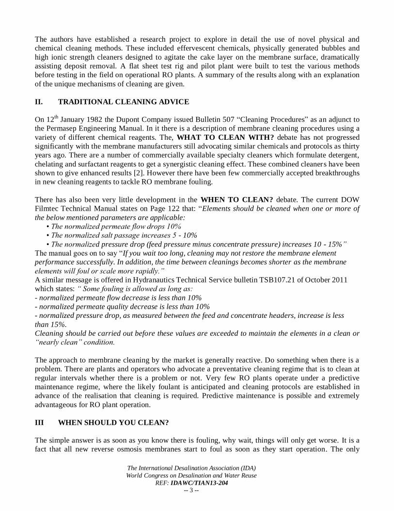
variable to this is the rate at which they foul. Most RO plants operate at a differential pressure (∆P) of
1.5 - 3 bar. Cleaning usually occurs when the ∆P is 10-15% above the design specification. This is based
on recommendations by membrane manufacturers. Figure 1 below demonstrates fouling with time. The
perception threshold line indicates the border at which the operator ‘perceives’ a change to system
operation, whether this be a change in flux, pressure, or salt passage. In fact as soon as water passes
along the membrane (initial time = T0), the membrane starts fouling.
Figure 1: Benefits of Predictive early cleaning
As we have already discussed all membranes are fouling from system start up, but the operational
effects are not observed until the fouling line crosses the perception line.. The membrane acts like a
huge sponge with a myriad of active surfaces, a significant amount of surface fouling can take place
before any operational change is observed [8]. The objective of every Cleaning in place (CIP) procedure
should be to fully remove all foulants to minimize the required cleaning frequency of the membranes.
Operation experience and plant performance data indicates that choosing when to clean, cleaning
procedure and chemical selection has a significant impact on reducing membrane cleaning frequency
and therefore operational costs.
Laboratory studies from numerous autopsies have confirmed that “speed is of the essence” ie. The
sooner the membrane is cleaned after fouling is observed the easier it is to clean. If the foulant is not
cleaned it becomes more difficult to remove completely, requiring significant specialty chemical
application and increased CIP downtime. Reactive clean 1 will theoretically take place when perceived
performance has dropped by 10-15%. In reality plant operators are also governed by external factors
such as production cycles which may mean that by the time a suitable shutdown period is arranged the
performance may have got significantly worse. The subsequent clean may still result in operating
conditions returning to an acceptable level below the fouling perception threshold. The clean after a
delay will not be as effective as it could have been if performed earlier. Whilst large amounts of deposits
can still be removed those compressed closest to the membrane surface are unlikely to be cleaned
resulting in a higher subsequent fouling rate. The resulting loss in operational performance will be much
quicker than if a more thorough clean had been achieved. Reactive clean 2 will therefore be conducted
after a shorter period than may otherwise have been possible had the first clean happened earlier and
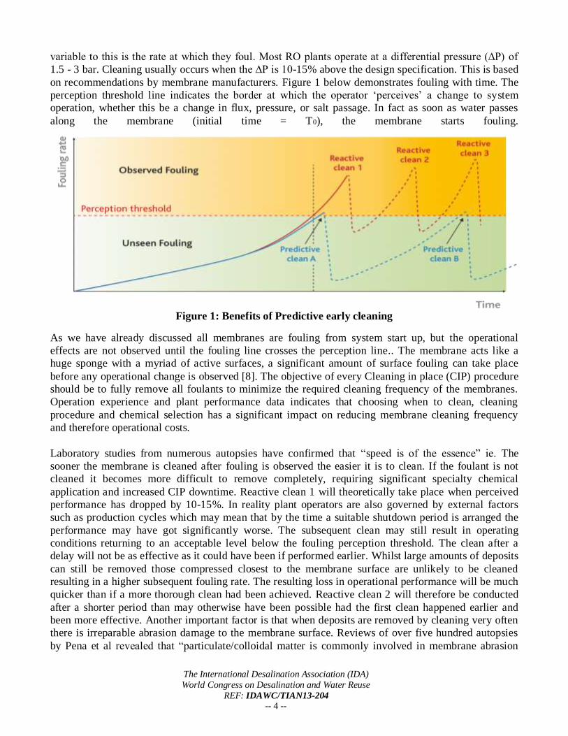
been more effective. Another important factor is that when deposits are removed by cleaning very often
there is irreparable abrasion damage to the membrane surface. Reviews of over five hundred autopsies
by Pena et al revealed that “particulate/colloidal matter is commonly involved in membrane abrasion
The International Desalination Association (IDA)
World Congress on Desalination and Water Reuse
REF: IDAWC/TIAN13-204 -- 5 --
phenomena during regular cleaning procedures.” [9] The scanning electron microscopy (SEM) images
below show physical damage to cleaned membranes.
Figure 2: SEM images of damaged membrane after cleaning
The CIP process can be optimised by conducting a “predictive” biopsy or post mortem type membrane
autopsy. During autopsy various scientific methods are employed to accurately identify the nature of a
foulant and this information can be used to plan the CIP procedure accordingly. Convincing some
operators of the benefits of removing and autopsying “good elements” may be difficult, so smaller 2 or 4
inch sacrificial elements could easily be installed or cartridge filters removed and analysed. Once the
foulants are identified optimum chemical and cleaning protocols can be assessed in the laboratory and
the most effective cleaning agents can be stored on site ready to begin the CIP as soon as there is a
notable change in operating parameters. Any delay in cleaning will mean the foulant will be become
thicker and more compressed into the membrane surface and be much more difficult and costly to clean
efficiently. Early maintenance cleaning of the plant prevents a buildup of difficult to remove deposits
which reduce membrane performance and life expectancy. Less time will be required to conduct the
cleaning and a more effective “deeper” clean can be achieved. This means the subsequent fouling rate is
lower. The lower fouling rate reduces the frequency between subsequent cleans increasing operational
efficiency and further enhancing membrane life.
IV. INNOVATIVE CLEANING MECHANISMS
This section reviews some novel processes and cleaning compounds that have been developed and tested
in the laboratory, pilot plant and actual operational RO plant. These novel approaches show the potential
to dramatically increase the efficiency of RO membrane cleaning.
4.1 Dislodgement by Natural Osmosis
High ionic strength cleaning compounds combining detergents, chelants, surfactants and effervescents
were formulated and tested in lab scale and pilot plant cleaning experiments During periods of soaking
the high ionic strength of the cleaning solution causes movement of permeate across the membrane
surface through natural osmosis. This low flow of permeate is sufficient to agitate and dislodge difficult
to remove foulants; in particular layers of biofilm or colloidal clay. This then enables the cleaning
compounds to further break up, disrupt and remove fouling particles. In operational RO plant reduction
in cleaning frequency by 4-6 times per year has been observed when using this technique.
The International Desalination Association (IDA)
World Congress on Desalination and Water Reuse
REF: IDAWC/TIAN13-204 -- 6 --
4.2 Effervescent Reagents
The effectiveness of effervescent compounds in cleaning reagents used in the food and beverage
industry and dental hygiene is well documented. A number of effervescent reagents were tested and
adopted in the formulation of powder membrane cleaning compounds. When the powder is dissolved in
permeate water to make up the cleaning solution the effervescent reagents evolve gas as bubbles which
physically agitate the foulant during cleaning circulation. This has a dual effect of physically removing
the foulant and increasing surface area of the cleaning reagents to the foulant surface.
4.3 Bubble Cleaning
Further agitation of deposits at the membrane surface was investigated using a high concentration and
wide distribution of bubble sizes which are known for cleaning a variety of deposits in different
industries. The cleaning effect occurs “when bubbles expand and collapse close to boundaries, a shear
flow is generated which is able to remove particles from the surface, thus locally cleaning it.”[10] This
phenomenon has been tested by numerous researchers notably Agarwal et al. “investigated the potential
of air for biofilm detachment from a nylon membrane surface in comparison to chemical cleaning by
sodium hypochlorite. About 88% of fixed biomass detachment was observed after 1 hour of air
bubbling, while only 10% of biofilm detachment was achieved in the control experiment without
bubbles.”[11] The effectiveness at removing biofilm and clay is of particular relevance for enhanced
cleaning of RO membranes.
V. TEST EQUIPMENT
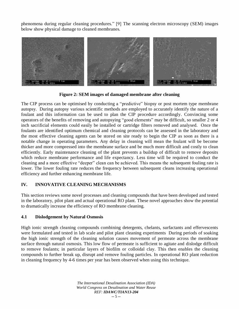
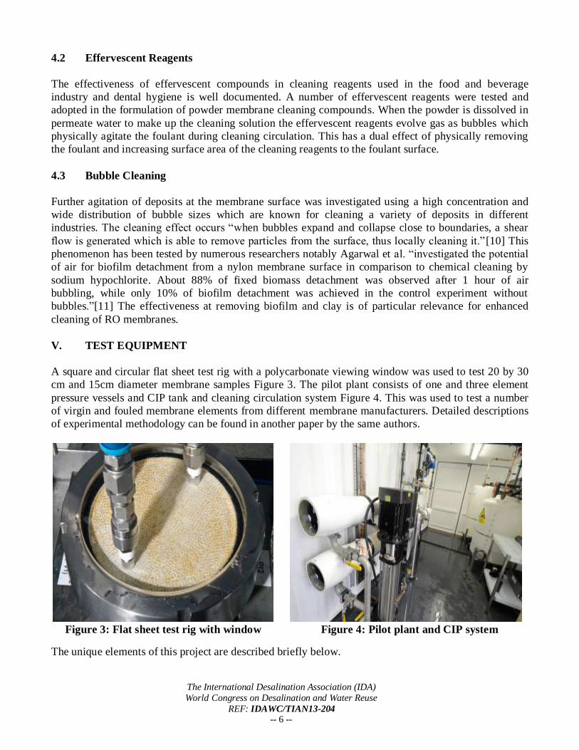
A square and circular flat sheet test rig with a polycarbonate viewing window was used to test 20 by 30
cm and 15cm diameter membrane samples Figure 3. The pilot plant consists of one and three element
pressure vessels and CIP tank and cleaning circulation system Figure 4. This was used to test a number
of virgin and fouled membrane elements from different membrane manufacturers. Detailed descriptions
of experimental methodology can be found in another paper by the same authors.
Figure 3: Flat sheet test rig with window Figure 4: Pilot plant and CIP system
The unique elements of this project are described briefly below.
The International Desalination Association (IDA)
World Congress on Desalination and Water Reuse
REF: IDAWC/TIAN13-204 -- 7 --
5.1 Microbubble generator
The bubbles are introduced by using a specially designed microbubble generator. If a pump forces a
fluid flowing into the microbubble generator tube an increase in velocity occurs in the constricted part
simultaneously with the decrease in pressure which leads to air being sucked in through the tube.
Pressure recovery takes place further downstream and the air bubbles drawn in collapse forming bubbles
which then have a tendency to coalesce into larger bubbles around the microbubble generator. In order
to optimize cleaning it is preferable to have micro and macro bubbles. [12] This can be achieved using
specially formulated cleaning agents which minimize the coalescing of micro, mini and midi bubbles
into larger bubbles. The size range for bubble description is shown in Table 1. The cleaning reagents
created a suspension of bubbles and cleaning solution which distributed evenly over the membrane
surface in a pulsed fashion. This phenomenon went helped alleviate the problems discovered by
Willems et al who could not get even distribution of bubbles across the membrane surface. [7]
Table 1 : Small bubble size and production method
Description Size Production
Nanobubble 0.5-5µm Ultra-sound, pressure
Microbubble 5-50µm Ultrasound, pressure, venturi, chemicals
Minibubble 50-100µm Venturi, chemicals
Midibubble 100-500µm Venturi, chemicals
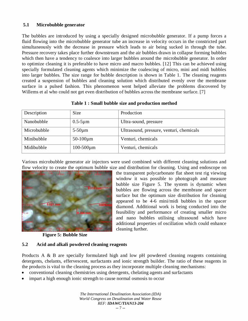
Various microbubble generator air injectors were used combined with different cleaning solutions and
flow velocity to create the optimum bubble size and distribution for cleaning. Using and endoscope on
the transparent polycarbonate flat sheet test rig viewing
window it was possible to photograph and measure
bubble size Figure 5. The system is dynamic when
bubbles are flowing across the membrane and spacer
surface but the optimum size distribution for cleaning
appeared to be 4-6 mini/midi bubbles in the spacer
diamond. Additional work is being conducted into the
feasibility and performance of creating smaller micro
and nano bubbles utilising ultrasound which have
additional properties of oscillation which could enhance
cleaning further.
Figure 5: Bubble Size
5.2 Acid and alkali powdered cleaning reagents
Products A & B are specially formulated high and low pH powdered cleaning reagents containing
detergents, chelants, effervescent, surfactants and ionic strength builder. The ratio of these reagents in
the products is vital to the cleaning process as they incorporate multiple cleaning mechanisms:
conventional cleaning chemistries using detergents, chelating agents and surfactants
impart a high enough ionic strength to cause normal osmosis to occur
The International Desalination Association (IDA)
World Congress on Desalination and Water Reuse
REF: IDAWC/TIAN13-204 -- 8 --
produce gaseous effervescing bubbles in the cleaning solution
stop air entrained bubbles coalescing so a suspension of mini and midi bubbles is created which are
particularly effective at cleaning deposits from surfaces
During our experiments we found that the cleaning reagents A & B when used at a 1-2% solution in
conjunction with the microbubble generator had a profound effect on the bubble size distribution and
also imparted a pulsing phenomenon on the cleaning solution after exit from the physical generator
device. This pulse could be clearly observed on the flat sheet test rig and through the clear rotameter on
the pilot plant. The cleaning solution is evenly distributed and we believe this unique pulsing effect of
the cleaning solution may also enhance the cleaning effect on fouled membranes.
VI. EXPERIMENTS
8-inch spiral wound elements obtained from different membrane manufacturers were used in the study.
These consisted of both fouled and new membranes, which were cleaned using the flat sheet test rigs
and pilot plant. Results of cleaning effectiveness could be measured by improvements in flow, pressure,
flux, monitoring the turbidity of cleaning solutions, detection of the poly-sulphone layer before and after
cleaning and using comparisons of infra-red wavelength spectrograms of blank fouled and cleaned
membranes. In addition, membranes were autopsied to further assess the cleaning performance. In order
for the RO market and membrane manufacturers to adopt this new cleaning technology rigorous
autopsying of cleaned membranes were conducted to demonstrate that no damage occurs to the
membrane. The results of this work are published in detail in a separate paper by the same authors.
VII. RESULTS
A large number of flat sheet test experiments have been done on a variety of fouled membrane samples.
Indications are that enhanced cleaning particularly of colloidal, biological and organic fouling can be
accomplished when combining small bubbles and effervescing high ionic strength powder cleaner.
7.1 Flat sheet test results
Membrane elements from six different RO plants that had been fouled with varying combinations of
clay, biofilm and iron were used to carry out a series of cleaning tests on the flat sheet test rig using a set
cleaning protocol:
The fouled membrane was characterised using a 2000ppm NaCl solution under standard test
conditions and flux measurement obtained.
A 2 hour clean was performed using a Cleaner A a 1% solution of effervescing, high ionic strength,
high pH, powder, Cleaner C a 0.2% sodium hydroxide solution, and Cleaner D a 2% solution of a
conventional liquid alkaline cleaner. The membrane was characterised again under standard test
conditions and the end flux measurement obtained.
Standard Test Conditions were:
The flux rate was measured at standard operating conditions for each membrane type
The recirculation rate was 1000 ml/min and normalized to 25°C
The cleaning solution was recirculated at ~2 bar for 30 minutes followed by a soak for 30
minutes followed by recirculation for 30 minutes and final soak and flush.
The International Desalination Association (IDA)
World Congress on Desalination and Water Reuse
REF: IDAWC/TIAN13-204 -- 9 --
Alkaline cleans were carried out at 35°C and a pH of 11.5-12.0
Table 2 below summarises the % increase in flux following cleans on eighteen membrane coupons
which were conducted with and without air for the different cleaning solutions A C & D.
Table 2: %flux increase after cleaning with and without air and cleaners A, C D
Sample GA120914 GA120869 GA120702 GA120652 GA120563 GA120747 Cleaner A C D A C D A C D A C D A C D A C D Average
No Air 32 4 28 38 30 27 -42 -59 -15 6 2 -12 8 6 6 10 6 8 4.6
Air 40 17 24 31 45 35 16 -34 2 30 12 25 40 2 15 24 15 11 19.4
The above results demonstrate that there is a significant improvement in flux after cleaning using the
micro-bubble generator. The best results were obtained using cleaner A and air. There are occasions
when cleaner C sodium hydroxide cleaning effect was not improved using air. This may be due to the
inability of the alkaline cleaning solution to reduce surface tension and cause a distribution of smaller
mini, midi and micro-bubbles. The resultant larger bubbles are less effective at removing deposits and
do not cover the membrane area evenly as demonstrated by Willems et al [7]. Sample GA120702 was
fouled with aluminium silicates and iron and flux deteriorated on most cleans apart from when air was
used. This could be due to the additional agitation of compacted layers of clay that had built up on the
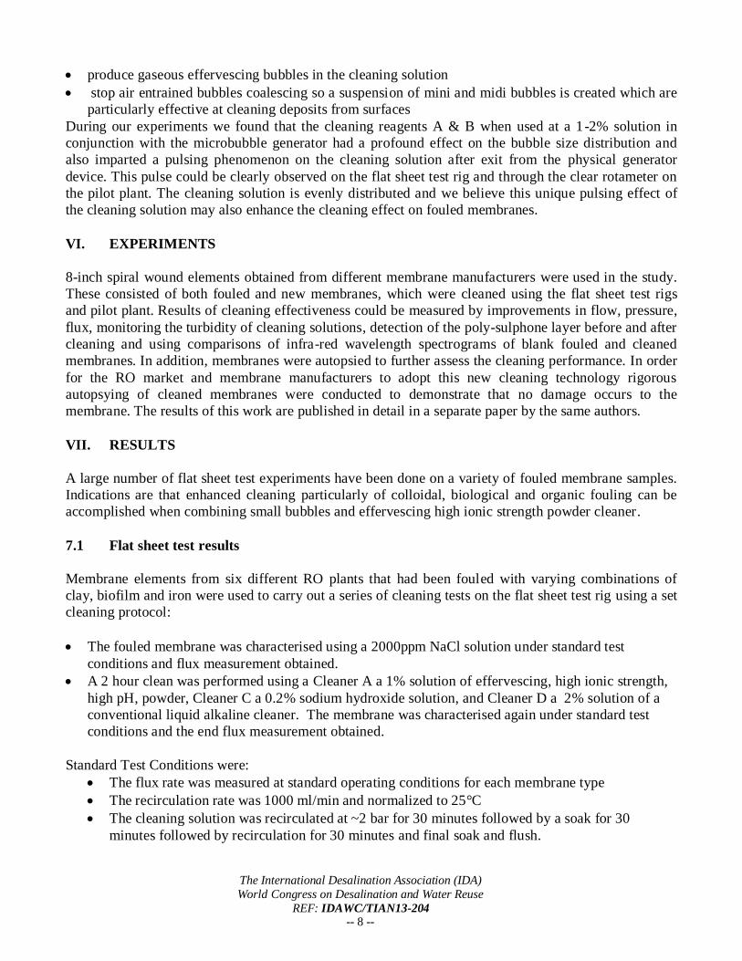
membrane surface. Sample GA120563 showed a dramatic increase in flux using cleaner A and air and a
slight improvement using cleaner D and air. These results are clearly shown from the membrane coupon
photos in Fig 6.
Figure 6: Fouled membrane After Cleaner A with Air After Cleaner D with Air
7.2 Scanning Electron Microscopy (SEM)
SEM was used to study the membrane surface and to verify the elemental composition of its foulant and
deposits detected. For conventional imaging using SEM, the samples must be electrically conductive at
the surface, and electrically grounded to prevent the accumulation of electrostatic charge at the surface.
Membrane samples are therefore coated with an ultrathin coating of an electrically conducting material,
in this case gold.
The International Desalination Association (IDA)
World Congress on Desalination and Water Reuse
REF: IDAWC/TIAN13-204 -- 10 --
The main components of the membranes are carbon, oxygen, nitrogen (which are not detectable by this
technique) and sulphur (polysulphone layer). In the absence of foulant, or when it is very thin, the
electron beam used for analysis can reach the polysulphone layer and hence sulphur is detected. So if we
see an increase in the amount of sulphur detected this is due to a cleaner membrane surface.
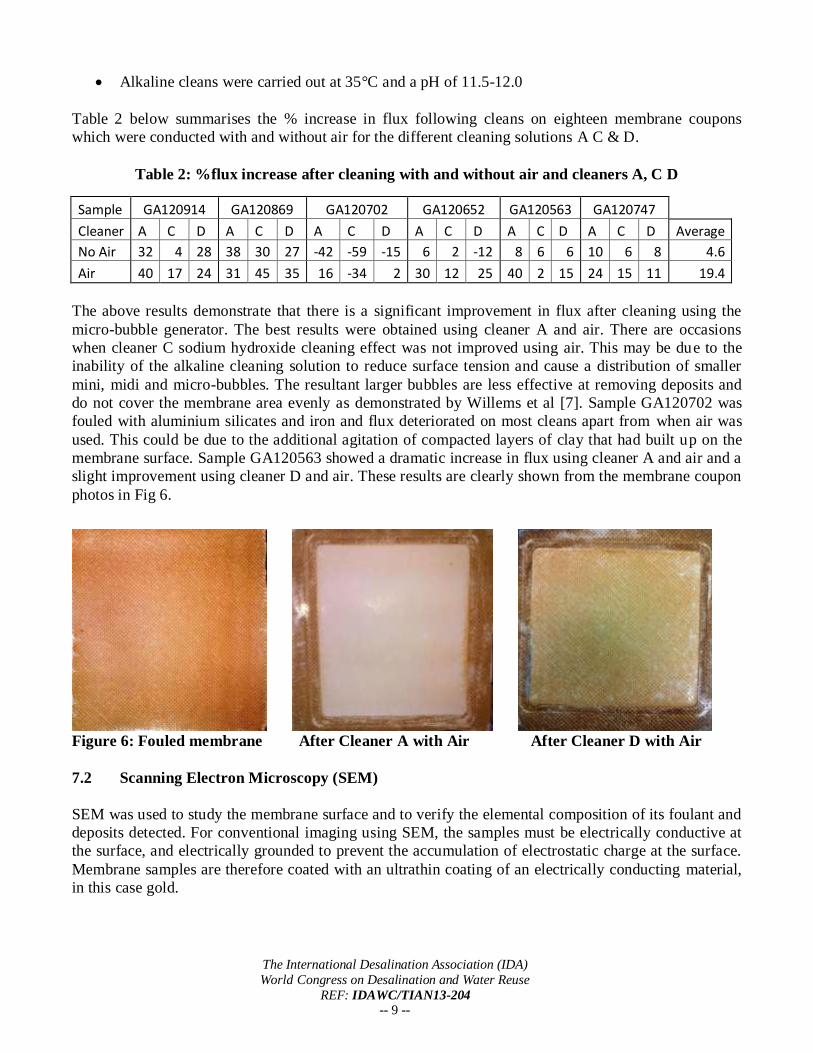
Sample GA120914 was a clay fouled membrane which was cleaned using high ionic strength powder
effervescing cleaners A & B with and without air. When used without air less sulphur was detected
indicating less of the polysulphone layer was being detected and therefore cleaning had not been as
effective. Clay consists of aluminium-silicate. Less aluminium and silicon was detected when cleaning
with air than in the case of cleans done without air. This indicates cleaning with air is more effective at
removing the deposits. A clean conducted without air still showed significant deposit removal as can be
seen in Figure 7 below.
Figure 7: Membrane sample showing enhanced clay removal with air
7.3 Pilot Plant Test Results
A number of fouled membrane elements have been sourced from operational RO plant and tested on the
pilot plant with different cleaners with and without the micro-bubble generator. Results are generally
encouraging indicating improved cleaning effectiveness particularly with clay and biofouled
membranes. Four heavily fouled membrane elements which had been replaced for new due to poor
performance were collected from a specialised tank storage site. A 10m3/hr reverse osmosis plant is
used to treat feed water received from an advanced membrane bioreactor (AMBR) used to remove a
broad range of trace organics, phenols and red list metals from site waste water prior to disposal.
The International Desalination Association (IDA)
World Congress on Desalination and Water Reuse
REF: IDAWC/TIAN13-204 -- 11 --
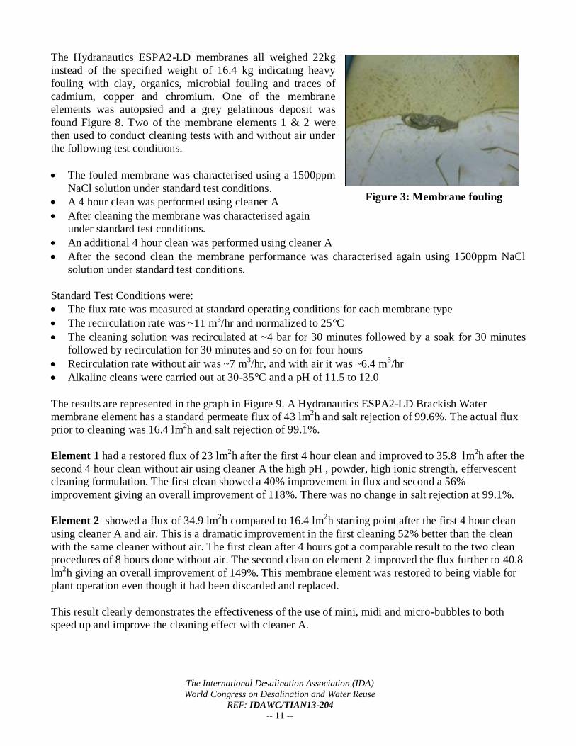
The Hydranautics ESPA2-LD membranes all weighed 22kg
instead of the specified weight of 16.4 kg indicating heavy
fouling with clay, organics, microbial fouling and traces of
cadmium, copper and chromium. One of the membrane
elements was autopsied and a grey gelatinous deposit was
found Figure 8. Two of the membrane elements 1 & 2 were
then used to conduct cleaning tests with and without air under
the following test conditions.
The fouled membrane was characterised using a 1500ppm
NaCl solution under standard test conditions.
A 4 hour clean was performed using cleaner A
After cleaning the membrane was characterised again
under standard test conditions.
An additional 4 hour clean was performed using cleaner A
After the second clean the membrane performance was characterised again using 1500ppm NaCl
solution under standard test conditions.
Standard Test Conditions were:
The flux rate was measured at standard operating conditions for each membrane type
The recirculation rate was ~11 m3/hr and normalized to 25°C
The cleaning solution was recirculated at ~4 bar for 30 minutes followed by a soak for 30 minutes
followed by recirculation for 30 minutes and so on for four hours
Recirculation rate without air was ~7 m3/hr, and with air it was ~6.4 m
3/hr
Alkaline cleans were carried out at 30-35°C and a pH of 11.5 to 12.0
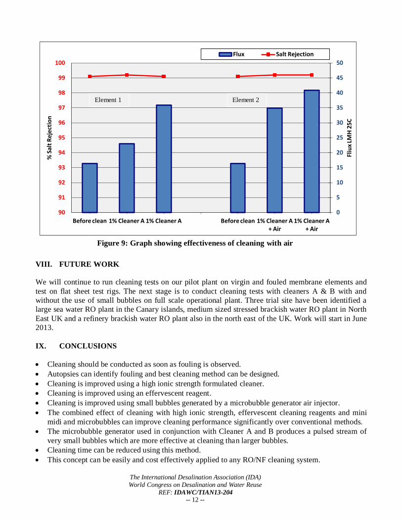
The results are represented in the graph in Figure 9. A Hydranautics ESPA2-LD Brackish Water
membrane element has a standard permeate flux of 43 lm2h and salt rejection of 99.6%. The actual flux
prior to cleaning was 16.4 lm2h and salt rejection of 99.1%.
Element 1 had a restored flux of 23 lm2h after the first 4 hour clean and improved to 35.8 lm
2h after the
second 4 hour clean without air using cleaner A the high pH , powder, high ionic strength, effervescent
cleaning formulation. The first clean showed a 40% improvement in flux and second a 56%
improvement giving an overall improvement of 118%. There was no change in salt rejection at 99.1%.
Element 2 showed a flux of 34.9 lm2h compared to 16.4 lm
2h starting point after the first 4 hour clean
using cleaner A and air. This is a dramatic improvement in the first cleaning 52% better than the clean
with the same cleaner without air. The first clean after 4 hours got a comparable result to the two clean
procedures of 8 hours done without air. The second clean on element 2 improved the flux further to 40.8
lm2h giving an overall improvement of 149%. This membrane element was restored to being viable for
plant operation even though it had been discarded and replaced.
This result clearly demonstrates the effectiveness of the use of mini, midi and micro-bubbles to both
speed up and improve the cleaning effect with cleaner A.
Figure 3: Membrane fouling
The International Desalination Association (IDA)
World Congress on Desalination and Water Reuse
REF: IDAWC/TIAN13-204 -- 12 --
VIII. FUTURE WORK
We will continue to run cleaning tests on our pilot plant on virgin and fouled membrane elements and
test on flat sheet test rigs. The next stage is to conduct cleaning tests with cleaners A & B with and
without the use of small bubbles on full scale operational plant. Three trial site have been identified a
large sea water RO plant in the Canary islands, medium sized stressed brackish water RO plant in North
East UK and a refinery brackish water RO plant also in the north east of the UK. Work will start in June
2013.
IX. CONCLUSIONS
Cleaning should be conducted as soon as fouling is observed.
Autopsies can identify fouling and best cleaning method can be designed.
Cleaning is improved using a high ionic strength formulated cleaner.
Cleaning is improved using an effervescent reagent.
Cleaning is improved using small bubbles generated by a microbubble generator air injector.
The combined effect of cleaning with high ionic strength, effervescent cleaning reagents and mini
midi and microbubbles can improve cleaning performance significantly over conventional methods.
The microbubble generator used in conjunction with Cleaner A and B produces a pulsed stream of
very small bubbles which are more effective at cleaning than larger bubbles.
Cleaning time can be reduced using this method.
This concept can be easily and cost effectively applied to any RO/NF cleaning system.
0
5
10
15
20
25
30
35
40
45
50
90
91
92
93
94
95
96
97
98
99
100
Before clean 1% Cleaner A 1% Cleaner A Before clean 1% Cleaner A + Air
1% Cleaner A + Air
Fliu
x LM
H 2
5C
% S
alt
Re
ject
ion
Flux Salt Rejection
Element 1 Element 2
Figure 9: Graph showing effectiveness of cleaning with air
The International Desalination Association (IDA)
World Congress on Desalination and Water Reuse
REF: IDAWC/TIAN13-204 -- 13 --
X. ACKNOWLEDGEMENTS
The authors would like to thank the Technology Strategy Board and Sue Wigram for their technical and
financial support. Without the supply of membrane elements to test, this work would not have been
possible. We would like to recognize the enthusiasm and interest of Trevor Henricksson who kindly
donated membrane elements and also Charles Cailliez, Daniel Shackleton and Tony Casanas for their
assistance in getting membrane samples to analyse.
XI. REFERENCES
[1] N. Peña, S. Gallego, F. del Vigo, S.P. Chesters. Evaluating impact of fouling on reverse osmosis
membrane performance.EDS Conf Barcelona 2012
[2] Wui Seng Ang, Ngai Yin Yip, Alberto Tiraferri, Menachem Elimelech. Chemical cleaning of RO
membranes fouled by wastewater effluent: Achieving higher efficiency with dual-step cleaning
Journal of Membrane Science 382 (2011) 100– 106
[3] Ng, H. Y. and Winters, H., A Novel 16-Inch RO System for Water Reuse and Desalination. Israel
Desalination Society Annual Conference, 19-20 December, 2006.
[4] Liberman, B., Methods of direct osmosis membrane cleaning online for high SDI feed after
pretreatment, IDA Workshop,Tampa – San Diego, 22-26/03/04.
[5] Labib Mohamed E, Elgin Ernest, Lai Richard C Y, Murawski Joseph, Tabani Yacoob, Weitzel,Steven A.
Pilot Scale Testing of Membrane Desalination System Utilizing Novel Two-Phase Cleaning Technology
Desalination and Water Purification Research and Development Program Report No. 121 May 2008
[6] S.A. Avlonitis, K. Kouroumbas, N. Vlachakis, Energy consumption and membrane replacement cost
for seawater RO desalination plants. Desalination Volume 157, Issues 1–3, 1 August 2003, Pages 151–8
[7] P. Willems, A.J.B. Kemperman, R.G.H. Lammertink,∗ , M.Wessling, M. van Sint Annaland,
N.G. Deen, J.A.M. Kuipers,W.G.J. van der Meer Bubbles in spacers: Direct observation of bubble
behavior in spacer filled membrane channels. Journal of Membrane Science 333 (2009) 38–44
[8] E. Darton, Role of chemicals in a thirsty planet International Desalination World Congress Perth
Australia IDAWC Ref PER11-262
[9] N. Peña, S. Gallego, F. del Vigo, S.P. Chesters. Evaluating the impact of fouling, on reverse osmosis
membrane performance. International Desalination World Congress Perth Australia IDAWC Ref
PER11-370
[10] Claus-Dieter Ohl, Manish Arora, Rory Dijkink, Vaibhav Janve, and Detlef Lohse. Surface cleaning
from laser-induced cavitation bubbles Applied Physics letter 89, 074102-1-3 August 2006
[11] Ashutosh Agarwal , Huijuan Xu , Wun Jern Ng and Yu Liu. Biofilm detachment by self-collapsing
air microbubbles: a potential chemical-free cleaning technology for membrane biofouling.
J. Mater. Chem., 2012,22, 2203-2207
[12] A. Fujiwara, S. Takagi, K. Watanabe, Y. Matsumoto. Experimental study on the new micro-bubble
generator and its application to water purification system. 4th
Proceeding ASME/JSME Honolulu US
2003.
Top Related