


Languages
Pages
Legal


ORIGINAL PAPER
Reverse electrodialysis: evaluation of suitable electrode systems
J. Veerman • M. Saakes • S. J. Metz •
G. J. Harmsen
Received: 15 September 2009 / Accepted: 27 March 2010 / Published online: 29 April 2010
� The Author(s) 2010. This article is published with open access at Springerlink.com
Abstract Reverse electrodialysis (RED) is a method for
directly extracting electrical energy from salinity gradients,
especially from sea and river water. For the commercial
implementation of RED, the electrode system is a key
component. In this paper, novel electrode systems for RED
were compared with existing systems on safety, health,
environment, technical feasibility and economics. Systems
with inert DSA-type electrodes and a NaCl–HCl supporting
electrolyte with the reversible Fe2?/Fe3? redox couple or
the [Fe(CN)6]4–/Fe(CN)6]3– couple achieved the highest
ranking. Improvements of the electrode system are also
discussed like the use of special stable metal electrodes,
graphite electrodes, other reversible redox couples, capac-
itive electrodes and electrolytes with carbon particles.
Keywords Reverse electrodialysis � Electrode reaction �Salinity gradient power � Electrodialysis � Stack design �Power production
Abbreviations
AEM Anion exchange membrane
DC Direct current
CEM Cation exchange membrane
CDI Capacitive deionization
DEA Data envelopment analysis
DSA Dimensionally stable anode
ED Electrodialysis
EDR Electrodialysis reversal
EMF Electromotive force
ES Electrode system
GS Generating system
MMO Mixed metal oxide
PRO Pressure retarded osmosis
RED Reverse electrodialysis
SHE Standard hydrogen electrode
SHE Safety, health and environment
SGP Salinity gradient power
Definitions
Compartment Space between the membranes
Cell Combination of two membranes and
two compartments
Generating system A number of N cells without the
electrode system
Electrode system Anode, cathode, electrode rinse and
outer membranes
Stack A number of N cells with an
electrode system
1 Introduction
Energy can be generated from the reversible mixing of salt
solutions with different concentrations and is called salinity
J. Veerman � M. Saakes � S. J. Metz (&)
Wetsus, Centre of Excellence for Sustainable Water Technology,
P.O. Box 1113, 8900 CC Leeuwarden, The Netherlands
e-mail: [email protected]
J. Veerman
e-mail: [email protected]
J. Veerman
Department of Life Sciences and Technology, Noordelijke
Hogeschool Leeuwarden, Agora 1, 8934 CJ Leeuwarden,
The Netherlands
G. J. Harmsen
University of Groningen, Nijenborgh 4, 9747 AG Groningen,
The Netherlands
123
J Appl Electrochem (2010) 40:1461–1474
DOI 10.1007/s10800-010-0124-8

gradient power (SGP). The energy that theoretically can be
generated per m3 river water is 1.7 MJ when mixed with
the same volume sea water or even 2.5 MJ when mixed
with a large surplus of sea water [1]. Post et al. proved
experimentally that it is possible to convert 85% of this
potential energy into useful electricity [2]. Wick and
Schmitt [3] estimated the total global salinity power to be
2.6 TW, which is sufficient to supply the global electricity
demand (2 TW) or 16% of the total present energy
consumption [4].
There are two membrane technologies capable of con-
verting this potential energy into electricity: reverse elec-
trodialysis (RED) [5–7] and pressure retarded osmosis
(PRO) [8, 9]. Both PRO and RED are sustainable tech-
nologies without CO2 or other emissions. The only product
is brackish water which is also formed when a river flows
directly in the sea. Moreover, there is no thermal pollution:
the conversion of entropy into electrical energy causes a
slight decrease of the water temperature of about 0.1 K if
all the potential energy is extracted [10]. Post et al. [11]
showed that in the case of using seawater with river water,
RED is a good choice. In 1954 Pattle already [5–7] showed
the opportunities of this method.
A RED stack consists of a large number of cells. An
example of a RED stack with only one cell is shown in
Fig. 1. The cell consists (from left to right in the figure) of
an anion exchange membrane (AEM), a sea water com-
partment, a cation exchange membrane (CEM) and a river
water compartment. On the right side, the stack contains an
extra AEM. The ions in the sea water diffuse through the
membranes to the river water: the Na? ions through the
CEM and the Cl- ions through the AEM. The positive Na?
movement to the right and the negative Cl- movement to
the left add together to a positive ionic current to the right.
The electromotive force of such a cell is 175 mV if pure
NaCl solutions are used of 1 and 30 g l-1 and ideal
membranes are applied; practical cell voltages under con-
ditions of maximal power generation are about 60 mV [1].
In practice, a large number of cells (N) is used, in the range
from 50 in laboratory equipments to 1000 or more in
commercial RED plants [1].
The N cells together are designed as ‘generating system’
(GS). At the electrodes, the ionic current is converted into
an electron current. The electrode system (ES) consists at
least of four parts: (i) electrodes, (ii) anolyte and catholyte,
(iii) outer membranes, and (iv) technical equipment for
recirculating the electrode rinse solution. Eventually the
electrode rinse solution (pH etc.) is controlled by an
additional system.
In principle, the recirculation system of the electrode
rinse solution can cause short-circuiting of the RED stack.
However, if the resistance of this recirculation system is
much higher then the internal resistance of the stack, this
effect can be ignored. This can be done by applying rela-
tively long tubes to the recirculating system.
The electrode system as shown in Fig. 1 is equipped
with inert electrodes with a reversible redox couple con-
taining Fe2?/Fe3? ions in a NaCl–HCl supporting electro-
lyte. The potential difference needed for reduction of Fe3?
to Fe2? on the cathode is counterbalanced by the oxidation
of Fe2? to Fe3? at the anode. Under zero current condi-
tions, the total cell electromotive force (EMF) is obtained
at the working electrodes. The Fe3?/Fe2? ratio is kept
constant by recirculation the combined anolyte and cath-
olyte through the electrode compartments. This type of
redox system is called a homogeneous charge transfer
reaction because all reactants are present in the same phase.
In order to reduce the relative power loss of the electrode
system, RED stacks should have a large number of cells.
In literature many electrode systems are described for
RED. These systems are all used on laboratory scale and
none of these systems has been evaluated for its practical
applicability on a real scale. Many aspects of the electrode
system are important for its operation: electrochemical
reactions, energy consumption, transport through the
membranes of the electrode system, reversibility etc. The
objective of this paper is to compare these electrode sys-
tems for their suitability for RED. The evaluated systems
include those already described in literature, but also
contains electrode systems as used in supercapacitors,
redox flow battery, electrodialysis and capacitive deioni-
zation, which might also be useful for RED.
Fig. 1 A RED stack with only one cell
1462 J Appl Electrochem (2010) 40:1461–1474
123

2 Electrode systems for RED
2.1 Classical systems
To be fair to the pioneers of RED, it should be mentioned
that their electrode systems were designed for laboratory
use and were not developed for real applications. However,
we have used their systems in our comparison because their
solutions vary so widely.
2.1.1 Overview
Table 1 shows the different published electrode systems for
RED. These electrode systems can be classified into two
groups: with or without opposite electrode reactions. First,
for systems with opposite electrode reactions and a recir-
culating electrode rinse, there is no net chemical reaction.
These systems have a zero equilibrium voltage. A RED
system with such an electrode system can generate elec-
trical energy with only a few cells because there is no
energy consumption for a net chemical reaction. Another
advantage is that there is no loss of chemicals (except for
transport through the outer membranes) and no gas pro-
duction. Pattle [6, 7] used copper gauze electrodes in a
CuSO4 solution. On the cathode the dissolved Cu2? was
reduced to metallic copper and at the anode the copper was
oxidized to Cu2?. With a typical RED current density of
5 mA cm-2 this effect on the thickness of electrodes is
about 2 mm per week. Jagur-Grodzinski and Kramer [12]
and Audinos [13, 14] used zinc electrodes with a ZnSO4
electrode rinse solution. In another experiment Audinos
used Ag/AgCl electrodes in a NaCl solution [13, 14].
In all these processes the electrodes play an active role
in the redox process: one electrode is growing and the other
is dissolving. In such systems the feed waters should be
interchanged periodically to invert the direction of the
electrical current and with that the electrode processes.
This imposes limitations on the stack design: the stack
should be equipped with identical sea and river water
compartments. A less attractive solution is to mechanically
perform the periodical interchange of anode and cathode.
This reversal can be avoided by taking a homogeneous
redox couple with inert electrodes. This may be platinized
titanium for both electrodes, special coated titanium for
specific anode and cathode and carbon or steel for the
cathode. Jagur-Grodzinski and Kramer used platinized
carbon electrodes in their so called ‘REF system’, a com-
bination of a RED system and the electrode system of a
fuel cell. At the anode water is oxidized to O2 and at the
cathode oxygen from air is reduced to water. Because the
electrode solution contained NaCl, it is also possible that
Cl2 is evolved at the anode. Veerman et al. used a system
with FeCl2 and FeCl3 in a NaCl bulk as described in Sect.
2.2.1, the system K4Fe(CN)6 with K3Fe(CN)6 in a NaCl
bulk [1, 15] and also a H2/Cl2 generating system with only
NaCl [10].
Second, the alternative for the systems with opposite
electrode reactions are the systems with gas generation.
The disadvantage of these systems is the loss of energy due
to these reactions; a significant number of cells should be
used to overcome the cell equilibrium voltage before
electricity production is possible. On laboratory scale the
problem can be solved by using a small number of cells
together with an external power supply. The virtual RED
voltage (the voltage without the losses at the electrodes) is
obtained from a pair of reference electrodes in the elec-
trode compartments near to the outer membranes. Wein-
stein and Leitz [16], Wick [17], Loeb [18], Metha [19] and
Suda et al. [20] reported such systems. At the cathode
hydrogen is evolved and at the anode chlorine is evolved if
a NaCl solution (or sea water) is used in the electrode
compartments. A possible succeeding reaction is hypo-
chlorite and chlorate formation [21]. Turek et al. avoided
the formation of chlorine by using an electrode rinse
solution with Na2SO4 [22, 23]. In this case oxygen is
generated at the anode.
2.1.2 Membranes of the described electrode systems
The sequence of the membranes in a RED stack is always
alternating, but for the outer membranes—confining the
electrode system—there are some requirements. The sys-
tems described in literature are given in Table 1. Some
authors (Weinstein and Leitz [16] and Suda et al. [20])
used seawater in the electrode compartments and applied
two different outer membranes, ensuring in this way an
alternating system of sea and river water compartments.
However, the generated Cl2 and ClO- are discharged into
the sea water which is unacceptable from the viewpoint of
safety, health and environment (SHE). Also the formation
of Cl2 requires the application of chlorine resistant outer
membranes.
Another possibility is to use a closed electrode system.
Veerman et al. [15] used a closed electrode rinse contain-
ing NaCl with CEMs as outer membranes. In this case the
negative ClO- is confined together with the Cl2 in the
electrode rinse. Although there is no direct discharge of
these products to sea water, the problem of disposing these
chemicals is not solved. Pattle [7] used a CuSO4 solution
and in Table 1 it is seen that the Cu2?-ions are maintained
in the electrode compartments by the outer AEMs. Al
though an AEM (with positively fixed charges) is slightly
permeable for monovalent (positive) co-ions, the bivalent
positively charged Cu2?-ions are strongly excluded and
Cu2?-loss is expected to be relatively low but not to be
negligible in terms of SHE. The SO42- in the electrode
J Appl Electrochem (2010) 40:1461–1474 1463
123

Table 1 Electrode systems described in literature
anode anolyte repeating catholyte cathode author
+ bulk unit + bulk electrode reactions
described systems in literature1 Cu CuSO4 ‡ S R ‡ CuSO4 Cu Pattle [5,6,7]
cath.: Cu2+ + 2e Cu
Cl– Na+ Cl– anode: Cu Cu2+ + 2e
net: nil
2 metal sea S R ‡ sea metal Weinstein/Leitz [16]
cath.: 2 H2O + 2e H2 + 2OH–
Na+ Cl– anode: 2 Cl– Cl2 + 2e
net: 2H2O + 2 Cl– H2 + 2OH– + Cl23 Ag/AgCl NaCl ‡ S R ‡ NaCl Ag/AgCl Audinos [13,14]
cath.: AgCl + e Ag + Cl–
Cl– Na+ Cl– anode: Ag + Cl– AgCl + e
net: nil
4 Zn ZnCl2 ‡ S R ‡ ZnCl2 Zn Jagur–Grodzinski/Kramer [12]
cath.: Zn2+ + 2e Zn
Cl– Na+ Cl– anode: Zn Zn2+ + 2e
net: nil
5 C/Pt NaCl R ‡ S R ‡ NaCl C/Pt Jagur–Grodzinski/Kramer [12]
air cath.: ½O2 + 2H+ + 2e H2O
Na+ Cl– Na+ Cl– anode: H2O ½O2 + 2H+ + 2e
and 2Cl– Cl2 + 2e
separated anolyte and catholyte
6 Ti/Pt Na2SO4 R ‡ S Na2SO4 Ti/Pt Turek [22, 23]
cath.: 2H2O + 2e H2 + 2OH–
Na+ Cl– Na+ anode: H2O ½ O2 + 2 H+ + 2e
net: H2O + 2 H2 + ½ O2
7 C sea S R ‡ sea C Suda [20]
cath.: 2 H2O + 2e H2 + 2OH–
Na+ Cl– anode: 2Cl– Cl2 + 2e
net: 2H2O + 2 Cl– H2 + 2OH– + Cl2used systems by author
8 Ti/RuIr Fe2+/Fe3+ ‡ S R ‡ Fe2+/Fe3+ Ti/RuIr Veerman et al. [this paper]
NaCl / HCl NaCl / HCl cath.: Fe3+ + e Fe2+
Cl– Na+ Cl– anode: Fe2+ Fe3+ + e
net: nil
9 Ti/RuIr Fe(CN)63– / R ‡ S Fe(CN)6
3– / Ti/RuIr Veerman et al. [1,15]
Fe(CN)64– Fe(CN)6
4– cath.: Fe(CN)63– + e Fe(CN)6
4–
NaCl Na+ Cl– Na+ NaCl anode: Fe(CN)64– Fe(CN)6
3– + e
net: nil
10 Ti/RuIr NaCl R ‡ S NaCl Ti/RuIr Veerman et al. [10]
Fe(CN)64– cath.: 2 H2O + 2e H2 + 2OH–
Na+ Cl– Na+ NaCl anode: 2Cl– Cl2 + 2e
net: 2H2O + 2 Cl– H2 + 2OH– + Cl2suggested systems11 graphite Fe2+/Fe3+ ‡ S R ‡ Fe2+/Fe3+ graphite Veerman et al. [this paper]
NaCl / HCl NaCl / HCl cath.: Fe3+ + e Fe2+
Cl– Na+ Cl– anode: Fe2+ Fe3+ + e
net: nil
12 graphite Fe(CN)63– / R ‡ S Fe(CN)6
3– / graphite Veerman et al. [this paper]
Fe(CN)64– Fe(CN)6
4– cath.: Fe(CN)63– + e Fe(CN)6
4–
NaCl Na+ Cl– Na+ NaCl anode: Fe(CN)64– Fe(CN)6
3– + e
net: nil
is the anode, cathode, cation exchange membrane and ‡ anion exchange membrane. The repeating unit is underlined.S stands for sea water
and R for river water. Direction of the ions through the membranes is designated by arrows
1464 J Appl Electrochem (2010) 40:1461–1474
123

system will be exchanged rapidly for Cl- from the sea
water. This exchange has no effect on the functioning of
the system as long as the Cu2? ions stay in the electrode
compartments.
Jagur-Grodzinski and Kramer [12] also used active metal
electrodes (zinc) but their design was improved by taking
Cl- as anion. Turek and Bandura [22] described a system
with a Na2SO4 electrode rinse in combination with anion
exchange outer membranes, evolving H2 at the cathode and
in first instance O2 at the anode. In such systems the SO42-
can be exchanged for Cl-. This can cause generation of Cl2because after some time there is enough Cl- in the electrode
rinse solution ([5 g l-1) to generate Cl2.
We conclude: if there is a closed electrode rinse loop, it
is possible to contain only one type of ion (anion or cation)
in the combined electrode compartments. In this case, the
outer membranes should be of the same kind (both AEM or
both CEM) and the ionic charge transport between the
water compartments to the electrode rinse solution is done
respectively by Cl- or by Na?.
2.2 Self-developed systems
In our laboratory, we used three different electrode rinse
solutions, always with the same DSA (dimensionally stable
anode) type electrodes: titanium mesh electrodes, coated
with Ru–Ir mixed metal oxides. These electrodes are
suitable as anode as well as cathode and therefore current
reversal is allowed. The first electrode rinse solution was
unpractical for laboratory use; the other two are described
in the different articles on RED performance [1, 10, 15].
2.2.1 Fe2?/Fe3? in NaCl–HCl
In order to avoid the large overvoltages of gas generating
systems, we first used the system Fe2?/Fe3? in a NaCl bulk
together with the mentioned inert electrodes. For an elec-
trode rinse containing FeCl2 (0.05 mol l-1), FeCl3(0.05 mol l-1) and NaCl (0.5 mol l-1), the resulting pH
was 2.4. The disadvantage of this system is that O2 oxi-
dizes Fe2? to Fe3? and H? diffuses through the outer
membranes, both causing an increase of the pH. After
prolonged use, the electrode rinse solution obtained a red
brownish color which can be explained by the formation of
iron(III) oxyhydroxides. Oxidation can be prevented by
means of an airtight system and the formation of insoluble
salts can be avoided by controlling the pH to a low value
(\2.3) by the addition of HCl. However, buffering with
HCl is difficult because anion exchange membranes are
somewhat permeable for H? and a constant supply of HCl
is necessary. In this way the pH of the effluent decreases
that which is unacceptable from an environmental view-
point. A possible solution is the use of an external
electrodialysis system with bipolar membranes, generating
NaOH as well as HCl. The NaOH can be directed to the
output stream and the HCl to the electrolyte. This process
is pH neutral and there are no environmental implications.
An internal electrodialysis system with bipolar membranes
(built in the RED stack) for the same purpose is patented by
Hamelers et al. [24].
2.2.2 [Fe(CN)6]4-/[Fe(CN)6]3- in NaCl
For the development and testing of RED systems in the
laboratory the Fe2?/Fe3? appeared to be rather unpractical.
Therefore, we changed to a quite stable system: the iron
hexacyanoferrate system:
Fe CNð Þ6� �3�þ e � Fe CNð Þ6
� �4�;
E0 ¼ 0:356 V vs: SHE:
This system is described in former articles [1, 15].
Again, the inert electrodes were used as described in Sect.
2.2. To prevent loss of the iron complex we used CEMs as
outer membranes. As long as the electrolyte is not in
contact with the AEMs, there are no problems to be
expected. However, in case of internal leakages,
hexanoferrate ions may poison the AEMs in the stack by
irreversible binding, eventually resulting in a decreased
performance [25].
2.2.3 NaCl
To prevent the poisoning of the membranes, we changed to
a pure NaCl solution in the electrode compartments. With
this system, we characterized some membrane pairs for the
use in RED stacks [10]. By applying CEMs as outer
membranes, the generated Cl2 and OCl- was kept within
the electrode system.
2.3 Proposal for a novel system: Fe2?/Fe3?
in NaCl–HCl with graphite electrodes
The formerly used DSA type electrodes (as described in Sect.
2.2) are designed for gas generation with low overvoltages.
However, in our electrode systems with a reversible redox
couple (the Fe2?/Fe3? system and the [Fe(CN)6]4-/
[Fe(CN)6]3- system) gas evolution is undesirable.
Therefore, we suggest the use of graphite electrodes in
these systems. Graphite electrodes have been extensively
studied for use in redox flow batteries. One of these energy
storage systems—the Fe/Cr system—uses the Fe2?/Fe3?
couple in the positive half-cell at low pH. It appears that
this system is well reversible in electrochemical sense [26].
Graphite felt is tested until current densities of
700 mA cm-2 [27] whereas the optimal current density at
J Appl Electrochem (2010) 40:1461–1474 1465
123

RED is much lower; Veerman et al. reported 4 mA cm-2
for their experiments whereas an improvement with a
factor 5 is expected in the future with high performance
membranes and spacers [1].
Advantages of carbon electrodes to Ti/Ru/Ir electrodes
are:
– No use of exhaustible precious metals.
– High overpotentials for gas formation.
There is no risk of evolvement of dangerous and
aggressive gasses (H2, O2 and Cl2). Even with a reversible
redox couple this may be the case if the flow of the elec-
trode rinse solution is obstructed locally.
A disadvantage of graphite may be the lower mechanical
stability with respect to DSA-type electrodes during longer
operation times and the need for a proper current collecting
system. Therefore, graphite electrodes may be advanta-
geous for the Fe2?/Fe3? system as well as for the
[Fe(CN)6]4-/[Fe(CN)6]3- system. We added such systems
to Table 3 (column 11 and 12). The rather good end scores
encourages further research on these systems.
2.4 Symmetry in RED stacks
If the sea and river water inlets of a RED stack are inter-
changed, the polarity of the generated voltage is reversed.
Consequently, the performance of the RED stack is unal-
tered if the generating system (GS) and the electrode sys-
tem (ES) are both symmetrical. It is evident that the
symmetrical properties of GS and ES are related.
2.4.1 Reversal of the electrical current
For some electrode systems periodical reversal is obliga-
tory as for systems with participating (one dissolving and
one growing) electrodes. These electrode systems are
designated as ‘obligatory reversal’ or ES1. Other systems
consist of ‘universal’ electrodes where reversal is possible
but not obligatory and are called ‘facultative reversal’ or
ES2. A third case consists of the specific electrodes that are
only suitable as cathode or as anode and in which reversal
of the electrical current is not possible. These are denoted
as forbidden interchange or ES3.
2.4.2 Interchange of the feed water in RED stacks
Just as with the electrode system, we distinguish for the
generating system between three types:
GS1: obligatory interchange
In RED, growth of microorganisms in the stacks may be
a serious problem. One approach to prevent this, is the
periodical interchange of the river and sea water inputs. A
comparable method is used for normal electrodialysis for
desalination purposes and is called ‘electrodialysis rever-
sal’ (EDR) [28, 29]. From experiments in the future, it may
be proven that such a procedure is necessary and we denote
this system as ‘obligatory interchange’’ or as GS1.
GS2: facultative interchange
If it should be proved that feed water interchange is not
beneficial for prevention of microbial growth or for
breaking down polarization layers, then this interchange is
not obligatory. If, besides that, the GS is symmetrical (with
identical sea and river water compartments), the inter-
change of sea and river water is also not forbidden. In this
case we have a ‘facultative interchange’ system or GS2.
GS3: forbidden interchange
Bottlenecks in stack design for RED are the hydrody-
namical fluid resistance in all compartments and electrical
resistance in river water compartments [1]. Optimization
can lead to an asymmetric stack: sea water compartments
may be thicker than river water compartments to reduce
hydrostatic resistance without affecting electrical resis-
tance substantially; also length and width can differ. In
such a stack interchanging sea and river water is possible
for cleaning purposes but during this interchange the power
production is low. We call this a ‘forbidden interchange’
system GS3; although the adjective forbidden should not to
be interpreted strictly.
2.5 Voltage losses in electrode systems
Electrode systems introduce a voltage loss in the RED
system due to an overpotential, concentration polarization,
an ohmic potential and a Nernst potential in each electrode
compartment. In RED, current densities are relatively low
(in our own experiments about 4 mA cm-2 [1]) and the
losses due to concentration polarization and the ohmic
potential are minimal. This is a general property of all
studied electrode systems for RED. Further, with respect to
voltage losses, these systems can be divided in low, high
and medium loss electrode systems.
Low loss In systems with opposite electrode reactions
and a recirculating electrode rinse, there is no net chemical
reaction and the Nernst voltages on both electrodes cancel
each other. In most of these systems no gas reactions are
involved and the overpotentials are low. The total voltage
loss in the whole electrode system is about 0.1 V; which is
comparable to the generated voltage of 1-2 cells.
High loss Electrode systems with gas evolution have
higher voltage losses. For the electrolyses of water, the
needed voltage based on the Nernst equation is 1.23 V, and
the overpotentials are 0.03 V for H2 and 0.52 V for O2
evolution at a current density of 10 mA cm-2 [30], together
1.78 V. Because the typical cell voltage is about 60 mV
under power generating circumstances, a number of 30 cells
is used to overcome the voltage loss of this electrode system.
1466 J Appl Electrochem (2010) 40:1461–1474
123

Medium loss A special case is the so called ‘REF sys-
tem’ of Jagur-Grodzinski and Kramer [12] (system 5 in
Table 1). At the anode O2 is evolved and at the cathode O2
is consumed, so there is no net generation of O2. Because
there are separated anode and cathode compartments, the
net reactions is: H2O ? H? ? OH-. This water dissoci-
ation in ions consumes about 15 kJ mol-1 [31], much
lower than the 286 kJ mol-1 as necessary for splitting of
water in H2 and O2 [32]. Therefore, this system is classified
in the category ‘medium loss’.
It should be noted that electrode losses are only
important in stacks with a small number of cells as in
laboratory equipments. In a stack with 1000 cells the loss
of a high loss system is only 3%. High loss systems are
assessed with minus 1 point with respect to low loss sys-
tems (Sect. 3.2.1.5 and Appendix A5).
3 Criteria for electrode systems
3.1 Method of assessment
In the assessment of electrode systems, all relevant aspects
concerning safety, health, environment (SHE), technical
feasibility and economics are taken into account. In total 13
of these aspects were considered. A judgment in a scale
from 0 (unacceptable) to 5 (good) is given. Because a
commercial RED power plant was never built so far, there
is no experience with the different systems under real
economical power producing circumstances. Nine different
electrode systems for RED are described in literature. To
rank the quality of different systems, there are a large
number of methods. Data envelopment analysis (DEA) is a
powerful method, especially because the different weight
factors are determined by the method itself. However, the
consequence is that the method is only applicable if the
number of systems is larger than the number of the aspects
[33, 34] and that is not the case in our current topic.
Often a much more simple system is used: the end result
is calculated as the arithmetic mean of the different marks.
However, to prevent compensation of bad marks by other
good aspects, we achieved the total rating by calculating
the geometric mean A of all (n) parts Ai. Each aspect Ai is
judged with a mark in the range from 0 (unacceptable) to 5
(good).
A ¼Yn
i¼1
Ai
!1n
ð1Þ
In fact, the geometric mean is closely related to the
logarithmic mean with the difference that the first method
can cope with zeros and the second method cannot. The
advantages of this way of ranking are: (i) unacceptable
systems are mentioned (judged as 0 on a single criterion) but
always remain at the lowest level of the ranking, (ii) there is
no need for ambiguous weight factors (iii) very different
variables can be used for different items; even nominal and
ordinal data can used together (iv) masking bad properties by
averaging with good properties hardly occurs.
For most items, the generating system (N cells of the
stack) is independent of the electrode system: each gener-
ating system can be combined with each electrode system.
An important exception to this rule is the aspect of feed water
interchange as discussed in Sect. 3.2.1.1. This aspect requires
a separate ranking system for stacks with obligatory, facul-
tative and forbidden river and sea water interchange.
3.2 Assessed aspects
In this paragraph, different aspects are summarized.
Applied criteria are included in the appendix. Aspects are
classified in three groups: (i) technical feasibility (5
aspects), (ii) safety, health and environment (SHE; 5
aspects) and (iii) economics (3 aspects). A larger number of
aspects in a group make this group more important in the
end score. Sometimes the classification is rather arbitrary.
3.2.1 Technical feasibility
3.2.1.1 Reversal of the electrical current/interchange of
the feed water Discussed in Sect. 2.4 are three types of
electrode systems and three types of generating systems.
Interchange of the feed water of a GS has consequences for
the electrode system: by the reversal of the direction of the
electrical current the anode becomes cathode and vise
versa. Table 2 shows the scores of the different combina-
tions. All combinations are permitted except GS3-ES1.
The combination GS1–ES3 is not strictly forbidden
because the following reason. Most modern electrodes are
designed specifically as cathode or as anode. Cathodes can
be made of different materials like stainless steel and
graphite; however, the requirements for anodes are much
higher than for cathodes. Special mixed metal oxide elec-
trodes based on thin layers of precious metals on titanium
can act both as anode and as cathode but their lifetime is
Table 2 Marking the different combinations of generating systems
with electrode systems
Reversal of the electrical current
ES1:obligatory ES2: facultative ES3: forbidden
Interchange of the water inlets
GS1: obligatory 4 5 1
GS2: facultative 5 5 5
GS3: forbidden 0 5 5
J Appl Electrochem (2010) 40:1461–1474 1467
123

severely lowered if current reversal is applied [35, 36]. In
some patents for electrodialysis (ED), systems are described
with composite electrodes [37–39]. These electrodes consist
of an alternate array of strips of anode and cathode material.
The power supply can be connected to the proper array on
each side, dependent on the electrical current direction. In
this way each used electrode material, as used in normal
ED, can also be used also in the EDR mode, an ED method
where the current is reversed periodically to prevent scaling
on the membranes. Composite electrodes can be used in
principle also for RED to cope with current reversal due to
interchange of sea water and river water. Therefore, this
‘forbidden’ combination GS1–ES3 is judged with 1 point.
The combination GS1–ES1 is not definitely ideal
because the GS and the ES may demand different switch
frequencies and therefore, only 4 points are noted.
3.2.1.2 Stability of anolyte/catholyte Most anolytes/
catholytes as listed in Table 1, contain only stable inor-
ganic ions. The exception is the electrolyte with the
hexacyanoferrate redox system. The complex ions in this
solution are able to decompose and to form stable insoluble
complexes with many multivalent metal ions with the risk
of poisoning the membranes.
3.2.1.3 Gas formation at the electrodes Gas formation
(Cl2 and O2 at the anode and H2 at the cathode) can cause
problems at the electrodes (electrical obstruction) and Cl2is highly corrosive. Besides this, Cl2 formation has a
negative environmental value (again called in aspect B3)
and H2 is an explosion hazard (again called in aspect B1).
3.2.1.4 Participating electrodes Participating electrodes
are already counted at the reversal item. However, dis-
solving and plating (growing) should be reversible many
thousand times. For example, it is known that Zn in this
way is a difficult metal and special provisions should be
taken with the electrode rinse.
3.2.1.5 Electrical properties of the electrode system
Voltage loss
As stated in Sect. 2.5, electrode systems can cause low,
medium or high losses. If at both electrodes opposite
electrochemical reactions occur in the same electrolyte, the
voltage loss is low; otherwise this loss is high. For a large
stack, this voltage loss is a minor problem.
Resistance of the electrode system
Electrodes are normally made from good conducting
materials. An exception is the Ag/AgCl electrode with a
thick AgCl layer where the Ag? has to diffuse from the
solution to the Ag surface. This system was described by
Audinos [16, 17] and included as system nr. 3 in Table 1.
3.2.2 Safety, health and environment
3.2.2.1 Safety H2 is explosive and especially dangerous
in closed spaces as sea containers or units for underwater
operation.
3.2.2.2 Health Toxicity is judged in case of skin and eye
contact, swallowing and inhalation. Especially organic
redox couples like hydroquinone/1,4-benzoquinone can be
a risk if in contact with the skin. The same holds true for
acidified solutions of the couple Fe2?/Fe3?. Nearly all
electrolytes are toxic if swallowed except NaCl solutions.
The most probable danger of inhalation is Cl2; HCN can be
evolved under extreme conditions (low pH, UV-light) from
the [Fe(CN)6]4-/[Fe(CN)6]3- couple.
3.2.2.3 Environment: normal exhaust of Cl2, ClO- and
ClO3- If sea water or NaCl is used in the electrode
system without a reversible redox couple, Cl2 can be
evolved at the anode and H2 at the cathode. If anolyte and
catholyte are combined, ClO- is formed and there is the
possibility of formation of ClO3- [21]. Sometimes these
products are useful (e.g. as biocide) but mostly they are
unwanted. To prevent contamination of the outlet streams
with ClO- and ClO3-, the outer membranes should be of
the CEM type. However, due to the non ideal behavior of
these membranes, there is also a small transport of these
anions into the effluent. If other ‘safe’ salts (Na2SO4,
NaNO3 etc.) are used in the electrode rinse solution, there
is still the danger of Cl2 evolvement because Cl- can
diffuse from the sea water compartment to the electrode
compartment through the CEM.
Even in the presence of a redox couple, Cl2 formation is
not excluded totally if Cl- is present in the electrode rinse
solution because the redox couple can be exhausted locally
due to obstructions in the flow path in the electrode
compartment.
If seawater is used as electrolyte, there is the possibility
of a closed electrode rinse loop or an open single pass
system. The last system is unacceptable from environ-
mental viewpoint due to the discharge of Cl2.
3.2.2.4 Environment: normal exhaust other chemicals In
principle, ions can be blocked by a proper choice of the
outer membranes although blocking of co-ions is not 100%.
Especially protons can easily pass the most types of AEMs.
Technically, the problems of transport from unwanted
species from the electrode compartments to the sea or river
water compartments and vice versa can be solved by using
double outer membranes. Between these outer membranes a
guard electrolyte is recirculated. Disadvantageous is the
need of conditioning this guard electrolyte.
1468 J Appl Electrochem (2010) 40:1461–1474
123

3.2.2.5 Environment: accidentally exhaust Loss of ano-
lyte/catholyte may occur by accident: rupture of the outer
membranes, human errors and defects in the electrode rinse
pumping system are possible causes. The effects of outer
membrane damaging can be decreased by using double
outer membranes as described above under B4. Defects in
the electrode rinse system can be controlled by leakage
tanks. Moreover, a RED installation is built modular and in
event of an accident only a small part of the electrolyte is
drained.
3.2.3 Economics
3.2.3.1 Special provisions for the anolyte/catholyte
The most frequent measures to be taken are:
a pH control
At low pH, H? can diffuse easily through AEMs to the
output stream and new H? should be added to the elec-
trolyte. This can be achieved by adding HCl; an environ-
mentally better way is the use an external electrodialysis
system with bipolar membranes generating NaOH and
HCl. The NaOH can be directed in the output stream and
the HCl to the electrolyte. This process is pH neutral.
b Redox control
In redox systems as Fe2?/Fe3?, the optimal Fe2?/Fe3?
ratio is about unity. However, by oxidation by air this ratio
may be affected. An airtight system should be used and/or
a reduction system should be incorporated.
c Concentration control
In fact, each anolyte/catholyte should be controlled,
especially electrolytes containing monovalents ions like
NO3- which can be exchanged rapidly with Cl- from the
sea water.
3.2.3.2 Price of the electrodes Inert electrodes can be
made of massive platinum, sometimes with added ruthe-
nium or iridium for mechanical strength. Such electrodes
are used in laboratories as measuring electrode or as
working electrode in different analytical processes. These
electrodes are very expensive and efforts have been made
to platinize other metals or carbon in such a way that the
inert properties of platinum are combined with the eco-
nomics of other metals. This resulted in platinum coated
titanium with 20–50 g platinum per square meter. These
electrodes are rather expensive and not catalytic enough for
gas evolving processes. The next step was the invention of
the so called ‘dimensional stable electrode’ (DSA) for the
chlor-alkali membrane process [40].
Modern stable electrodes consist of a metal support
(mostly titanium) with a mixed metal oxide (MMO) layer
[41]. The MMO consist of two components: one is a cat-
alytic and conducting (e.g. RuO2, IrO2, PtO0.12), the other
is inert and nonconducting (e.g. TiO2). The catalytic part of
the electrode cover is developed for special electrochemi-
cal purposes like Cl2 or O2 evolution. On these electrodes
the amount of precious metal is only 10–12 g m-2.
Moreover the price of iridium and especially of ruthenium
is much lower than of platinum. This may result in
acceptable prizes.
A further reduction of electrode price can be achieved
by using partial electrodes: electrodes with a reduced sur-
face by a proper dimensioning of a stretched metal process.
In RED, partial electrodes can be used because the current
density in the RED process is much lower than in other
electrochemical processes for which these electrodes are
developed.
Graphite electrodes are rather inexpensive. However, at
larger surfaces, current collection may be a problem and
results in a higher price.
3.2.3.3 Lifetime of the electrodes Marks for the aspects
of price (C2) and lifetime (C3) are generally opposite. In
our used criteria (Appendix) all DSA type electrodes get
the same judgment (mark = 5). The actual lifetime of
these electrodes is dependent on current direction (anodic
or cathodic use), electrolyte and current density. Fields of
application of electrodes with long erasing time are water
desalination with electrodialysis (ED) and the chlor-alkali
process. In normal ED for desalination, a 5-year life of a
platinum plated electrode is normal. Anode life was gen-
erally less than cathode life [42]. In fact all modern elec-
trodes are MMO covered on titanium (DSA type). For
chlorine evolving DSAs, as used in the chlor-alkali
industry, typical current densities are more then
300 mA cm-2 in the membrane cell process [43]. In this
case the lifetime of DSAs is guaranteed to be up to
10 years [44]. In contrast, optimal current densities in our
RED process were 4 mA cm-2 or possibly 20 mA cm-2 in
the future with improved systems [1]. Therefore, life time
of chlorine evolving DSAs may be expected to be much
more than 10 years for RED. For oxygen evolution, Chen
and Chen [45] predicted for their Ti/RuO2–Sb2O5–SnO2
electrode a life time of 8.3 years at a current density of
20 mA cm-2 and even 27 years at 10 mA cm-2. These
lifetimes are also an indication for use in RED electrode
systems. The foregoing refers to unidirectional use of the
electrodes. Current reversal (as in EDR) generally
decreases electrode lifetime substantially [42, 46].
4 Discussion
4.1 Described electrode systems
Described electrode systems in literature for RED are not
yet suitable for use in economical operated RED systems.
J Appl Electrochem (2010) 40:1461–1474 1469
123

A RED system should fulfill the requirements on safety,
health, environment, technical feasibility and economics.
In Table 3 the formulated criteria are applied to the dif-
ferent described electrode systems from Table 1 (for GS1
in bold, for GS2 regular and for GS3 in italics). The row
‘reversal to the electrical current’ (A1) is split up in three
parts for the combination of the different generating sys-
tems with the electrode system in question. The same goes
for the rows with the end-scores and ranks.
Table 3 shows that from the described used systems
(column 1–10), the iron system with Ti/Ru,Ir electrodes
(column 8) is the best system in combination with each of
the three generating systems.
The hexacyanoferrate system with the same electrodes
(column 9) may be useful in laboratory equipment. The
table also indicates that by application of graphite elec-
trodes the score of these systems is approached (column 11
and 12).
4.2 Proposal for improved electrode systems
Possible improvements are:
a Use of graphite electrodes
As indicated in Sects. 2.3 and 4.1, the use of graphite
electrodes in combination with homogeneous redox system
like Fe2?/Fe3? has good prospects.
b Improved electrodes of the DSA type
– Longer lifetime
For their experiments Veerman et al. [1, 11, 15] used
titanium mesh end electrodes, coated with Ru–Ir mixed
metal oxides. These electrodes are reversible (i.e. current
reversal is possible) and therefore usable for all types of
stacks. Lifetime of these electrodes is more than 10 years
under the applied current density (4 mA cm-2). An
improvement of the lifetime with a factor 5 can be
achieved with special Ir-MMO (mixed metal oxide) coated
titanium anodes and Ru-MMO coated cathodes; another
option is to use the extra stability of these electrodes for
reducing the cost of these electrodes by decreasing the
surface of the electrodes (the so called partial electrodes).
A limitation of this system is that frequent current reversal
during longer times is not possible with these electrodes.
– High overvoltages for Cl2/O2 evolution
The success of DSA type electrodes is due to a combi-
nation of high mechanical and electrochemical stability
with good catalytic properties and low overvoltages for
special electrode reactions. Especially such anodes are
developed for Cl2 and O2 generation. However, in a RED
process with a homogeneous redox couple (e.g. the Fe2?/
Fe3? or the system [Fe(CN)6]4-/[Fe(CN)6]3-), these reac-
tions are unwanted. Therefore, high overvoltages for gas
evolution are favorable to the process. It requires some
extra development to realize this with DSA type electrodes.
– Specific composite electrodes for RED
For use in normal electrodialysis some systems with
composite electrodes are patented [37–39]. These systems
allow current reversal with electrodes which are specifi-
cally usable as cathode or anode. In each current direction
only one part of each electrode is used. Eventually the
unused part can be protected with a low potential differ-
ence between this part and the adjacent part in operation.
c New homogeneous redox couple
Homogeneous redox systems (e.g. the system
[Fe(CN)6]4-/[Fe(CN)6]3-) do not cause net chemical
reactions and therefore the power losses are low. Most
organic homogeneous redox couples involve protons in
their reactions and special measures should be taken to
control the pH. However, there are many iron complexes
and possibly candidates are available that satisfy all men-
tioned criteria. The use of graphite electrodes may be
considered again in this case.
d Capacitive electrodes
The last decades, special high ion absorbing carbon has
been developed for use in super capacitors [47–50] and in
capacitive deionization (CDI) [51, 52]. If this material is
used as electrode in a RED stack, during a certain time an
internal ionic current can persist. The electrodes behave as
a capacitor and during that time there is also an external
electrical current. After some time, the process should be
inverted by changing the sea water and the river water feed.
It is obvious that the changing time is related to the resi-
dence time in the system. Assuming that time to be 1 min,
then a half period (the time between two feed interchanges)
should be at least about 60 min. Current RED stacks
operate at maximum power output with a current density of
about 4 mA cm-2 or 144,000 C m-2 h-1. The cathode
should adsorb then 144,000/F = 1.5 mol Na? and on the
anode the same amount of Cl- (F is the Faraday constant;
1 F = 96,485 C mol-1).
Typical specific capacitances are reported of 100–
200 F g-1 carbon in aqueous solution [47–50]. Using the
highest value of 200 F g-1, for an uploading to 1 V, there
is 200 F g-1 carbon needed. For a 1-h operation, the
electrodes should consist of 720 g carbon per m2. This
seems a realistic value for further development of such a
system.
In principle, the method is very clean and sustainable.
Carbon aerogel electrodes may have lifetimes of more than
10 years [53]. A restriction of this system is the obligatory
interchange. For optimal performance, the connected load
should be adapted continuously during one cycle. This is
possible with modern DC–DC converters. For normal
electrodialysis, such a system is patented by Wei et al. [54].
1470 J Appl Electrochem (2010) 40:1461–1474
123

Ta
ble
3R
ank
ing
the
syst
ems
des
crib
edin
lite
ratu
refo
rp
ract
ical
use
Des
crib
edsy
stem
sin
lite
ratu
reU
sed
syst
ems
by
auth
or
Su
gg
este
dsy
stem
s
12
34
56
78
91
01
11
2
Pat
tle
Wei
nst
ein
Au
din
os
Jag
ur-
GJa
gu
r-G
Tu
rek
Su
da
Vee
rman
Vee
rman
Vee
rman
Vee
rman
Vee
rman
An
oly
te/c
ath
oly
te:
Cu
SO
4N
aCl
NaC
lZ
nC
l 2N
aCl
Na 2
SO
4N
aCl
Fe3
?/F
e2?
HC
Fb
NaC
lF
e3?
/Fe2
?H
CF
b
Bu
lkN
aCl–
HC
lN
aCl
NaC
l–H
Cl
NaC
l
Cat
ho
de:
Cu
Ti/
Pta
Ag
/Ag
Cl
Zn
C/P
t/O
2T
i/P
tC
Ti/
Ru
,Ir
Ti/
Ru
,Ir
Ti/
Ru
,Ir
Gra
ph
ite
Gra
ph
ite
An
od
e:C
uT
i/P
taA
g/A
gC
lZ
nC
/Pt
Ti/
Pt
CT
i/R
u,I
rT
i/R
u,I
rT
i/R
u,I
rG
rap
hit
eG
rap
hit
e
Ty
pe:
ES
1E
S2
ES
1E
S1
ES
3E
S2
ES
2E
S2
ES
2E
S2
ES
2E
S2
Tec
hn
ical
feas
ibil
ity
GS
1A
1R
ever
sal
of
the
el.
curr
ent
45
44
15
55
55
55
GS
2A
1R
ever
sal
of
the
el.
curr
ent
55
55
55
55
55
55
GS
3A
1R
ever
sal
of
the
el.
curr
ent
05
00
55
55
55
55
All
A2
Sta
bil
ity
of
ano
lyte
/cat
ho
lyte
55
55
55
55
35
53
All
A3
Gas
form
atio
n5
25
54
42
55
25
5
All
A4
Par
tici
pat
ing
elec
tro
des
45
32
55
55
55
55
All
A5
Ele
ctri
cal
pro
per
ties
54
45
34
45
54
55
Saf
ety
,h
ealt
han
den
vir
on
men
t(S
HE
)
All
Bi
Hy
dro
gen
form
atio
n5
35
55
33
55
35
5
All
B2
To
xic
ity
43
54
35
34
43
44
All
B3
No
rmal
exh
aust
of
Cl 2
etc.
50
55
44
05
51
55
All
B4
No
rmal
exh
aust
oth
erch
em.
45
44
55
54
45
44
All
B5
Acc
iden
tall
yex
hau
st3
55
45
55
43
54
3
Eco
no
mic
s
All
C1
Sp
ecia
lp
rov
isio
ns
43
44
24
33
43
34
All
C2
Pri
ceo
fth
eel
ectr
od
es5
12
51
15
44
43
3
All
C3
Lif
eti
me
of
the
elec
tro
des
24
22
44
25
55
33
GS
1S
core
4.1
0.0
3.9
4.0
3.2
3.9
0.0
4.5
4.3
3.5
4.2
4.1
Ran
k4
11
76
10
71
11
29
35
GS
2S
core
4.2
0.0
4.0
4.1
3.6
3.9
0.0
4.5
4.3
3.5
4.2
4.1
Ran
k4
11
76
98
11
12
10
35
GS
3S
core
0.0
0.0
0.0
0.0
3.6
3.9
0.0
4.5
4.3
3.5
4.2
4.1
Ran
k8
88
86
58
12
73
4
Th
em
ark
sin
the
row
sA
1ar
ed
epen
den
to
nth
eg
ener
atin
gsy
stem
(GS
1,
GS
2o
rG
S3).
Th
esa
me
ho
lds
for
the
sco
re/r
ank
row
sat
the
bo
tto
ma
Ti/
Pt
assu
med
bH
CF
hex
acy
ano
ferr
ate
=F
e(C
N) 63
-/F
e(C
N) 64
-
J Appl Electrochem (2010) 40:1461–1474 1471
123
Brogioli succeeded in the reversal of the capacitive
deionization (CD) technique [55]. The capacitor is formed
by two activated carbon electrodes, immersed in the feed
solution, alternately salt and fresh water. When filled with
salt water, it is charged, and with fresh water it is dis-
charged. Charging and discharging are promoted by the
diffusion of ions and consequently there is a net energy
gain.
e Systems with an electrode rinse solution containing
carbon particles and/or ion exchange resin particles
These systems are described by Kedem et al. for use in
normal electrodialysis and patented [56, 57]. The electrode
rinse solution contains about 1% active carbon and 1%
cation exchange resin in a NaCl solution of about 2%. The
authors suggest that this system is based on the reversible
system
Hþ þ e � 1=2 H2
The H2 gas, as evolved at the cathode is adsorbed by the
carbon and transported to the anode where the reverse
reaction proceeds. The involved H? is transported by the
ion exchange resin:
RH þ Naþ � RNa þ Hþ
where RH is the resin in the acid form and RNa the resin in
the salt form.
The net reaction at the cathode and at the anode is
therefore:
RH þ Naþ þ e � RNa þ 1=2 H2
5 Conclusions
In this work, self-developed electrode systems and elec-
trode systems described in literature are compared on
safety, health, environment, technical feasibility and eco-
nomics. A robust system of judging the different systems is
presented. Applying this system to the described and used
systems, a ranking was made of the different electrode
systems. It is shown that the applicability of an electrode
system is related to the generating system. Three types of
generating systems can be distinguished: systems with (i)
obligatory, (ii) facultative and (iii) forbidden interchange
of the feed water inlets. The highest rankings for all the
three generating systems are found for the Fe2?/Fe3?
couple in a NaCl–HCl supporting electrolyte with bidi-
rectional Ru/Ir covered titanium electrodes.
This system is not ideal and may be improved for
application in commercial operating, large scale RED.
There are five interesting topics: (i) improved stable metal
electrodes (with longer lifetime, suitable for current
reversal and high overpotential for gas evolvement), (ii) a
new homogeneous redox couple (e.g. an iron complex),
(iii) a system with capacitive electrodes, (iv) a system with
an electrolyte, containing carbon particles and/or ion
exchange resin particles, and (v) the Fe2?/Fe3? couple in
combination with graphite electrodes. The last improve-
ment seems to be the most realistic alternative; however,
duration test should be performed under real RED condi-
tions to prove that it has sufficient mechanical and elec-
trochemical stability.
Acknowledgement This work was performed in the TTIW-coop-
eration framework of Wetsus, centre of excellence for sustainable
water technology (www.wetsus.nl). Wetsus is funded by the Dutch
Ministry of Economic Affairs, the European Union Regional Devel-
opment Fund, the province of Fryslan, the city of Leeuwarden and the
EZ/Kompas program of the ‘‘Samenwerkingsverband Noord-Neder-
land’’. The first author would like to thank the Noordelijke Hoge-
school Leeuwarden who facilitated this research by detaching him to
Wetsus and the participants of the theme ‘‘Energy’’ for their fruitful
discussions and their financial support.
Open Access This article is distributed under the terms of the
Creative Commons Attribution Noncommercial License which per-
mits any noncommercial use, distribution, and reproduction in any
medium, provided the original author(s) and source are credited.
Appendix
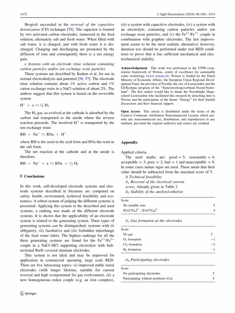
Applied criteria.
The used marks are: good = 5; reasonable = 4;
acceptable = 3; poor = 2; bad = 1 and unacceptable = 0.
In some cases minus signs are used. These mean that their
value should be subtracted from the maximal score of 5.
A Technical feasibility
A1 Reversal of the electrical current
score: Already given in Table 2
A2 Stability of the anolyte/catholyte
Score
No instable ions 5
[Fe(CN)6]4-, [Fe(CN)6]3- 4
A3 Gas formation at the electrodes
Score
No gas 5
O2 formation -1
Cl2 formation -2
H2 formation -1
A4 Participating electrodes
Score
No participating electrodes 5
Participating without problems (Cu) 4
1472 J Appl Electrochem (2010) 40:1461–1474
123
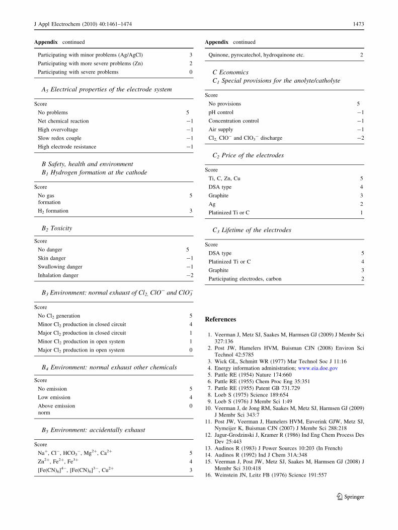
Appendix continued
Participating with minor problems (Ag/AgCl) 3
Participating with more severe problems (Zn) 2
Participating with severe problems 0
A5 Electrical properties of the electrode system
Score
No problems 5
Net chemical reaction -1
High overvoltage -1
Slow redox couple -1
High electrode resistance -1
B Safety, health and environment
B1 Hydrogen formation at the cathode
Score
No gas
formation
5
H2 formation 3
B2 Toxicity
Score
No danger 5
Skin danger -1
Swallowing danger -1
Inhalation danger -2
B3 Environment: normal exhaust of Cl2, ClO- and ClO3-
Score
No Cl2 generation 5
Minor Cl2 production in closed circuit 4
Major Cl2 production in closed circuit 1
Minor Cl2 production in open system 1
Major Cl2 production in open system 0
B4 Environment: normal exhaust other chemicals
Score
No emission 5
Low emission 4
Above emission
norm
0
B5 Environment: accidentally exhaust
Score
Na?, Cl-, HCO3-, Mg2?, Ca2? 5
Zn2?, Fe2?, Fe3? 4
[Fe(CN)6]4-, [Fe(CN)6]3-, Cu2? 3
Appendix continued
Quinone, pyrocatechol, hydroquinone etc. 2
C Economics
C1 Special provisions for the anolyte/catholyte
Score
No provisions 5
pH control -1
Concentration control -1
Air supply -1
Cl2, ClO- and ClO3- discharge -2
C2 Price of the electrodes
Score
Ti, C, Zn, Cu 5
DSA type 4
Graphite 3
Ag 2
Platinized Ti or C 1
C3 Lifetime of the electrodes
Score
DSA type 5
Platinized Ti or C 4
Graphite 3
Participating electrodes, carbon 2
References
1. Veerman J, Metz SJ, Saakes M, Harmsen GJ (2009) J Membr Sci
327:136
2. Post JW, Hamelers HVM, Buisman CJN (2008) Environ Sci
Technol 42:5785
3. Wick GL, Schmitt WR (1977) Mar Technol Soc J 11:16
4. Energy information administration; www.eia.doe.gov
5. Pattle RE (1954) Nature 174:660
6. Pattle RE (1955) Chem Proc Eng 35:351
7. Pattle RE (1955) Patent GB 731.729
8. Loeb S (1975) Science 189:654
9. Loeb S (1976) J Membr Sci 1:49
10. Veerman J, de Jong RM, Saakes M, Metz SJ, Harmsen GJ (2009)
J Membr Sci 343:7
11. Post JW, Veerman J, Hamelers HVM, Euverink GJW, Metz SJ,
Nymeijer K, Buisman CJN (2007) J Membr Sci 288:218
12. Jagur-Grodzinski J, Kramer R (1986) Ind Eng Chem Process Des
Dev 25:443
13. Audinos R (1983) J Power Sources 10:203 (In French)
14. Audinos R (1992) Ind J Chem 31A:348
15. Veerman J, Post JW, Metz SJ, Saakes M, Harmsen GJ (2008) J
Membr Sci 310:418
16. Weinstein JN, Leitz FB (1976) Science 191:557
J Appl Electrochem (2010) 40:1461–1474 1473
123

17. Wick GL (1978) Energy 3:95
18. Loeb S (1979) Patent US 4.171.409
19. Metha GD (1982) J Membr Sci 11:107
20. Suda F, Matsuo T, Ushioda D (2007) Energy 32:165
21. Czarnetzki LR, Janssen LJJ (1992) J Appl Electrochem 22:315
22. Turek M, Bandura B (2007) Desalination 205:67
23. Turek M, Bandura B, Dydo P (2008) Desalination 221:462
24. Hamelers HVM, Post JW, Metz SJ (2007) Patent WO 2007/
094659 A1
25. Lacey RE (1980) Ocean Eng 7:1
26. Lopez-Atalaya M, Codina G, Perez JR, Vazquez JL, Aldaz A
(1992) J Power Sources 39:147
27. Pupkevich V, Glibin V, Karamanev D (2007) Electrochem
Commun 9:1924
28. Katz WE (1979) Desalination 28:31
29. Grebenyuk VD, Grebenyuk OV (2002) Russ J Electrochem
38:906
30. International Critical Tables (1929) 6:339
31. Nagasubramanian K, Chlanda FP, Liu Kang-Jen (1977) J Membr
Sci 2:109
32. Lide DR (ed) (2004) Handbook of chemistry and physics, vol 5,
85th edn. CRC press, Boca Raton, pp 18
33. Charnes A, Cooper WW, Rhodes E (1978) Eur J Oper Res 2:429
34. Adler N, Friedman L, Sinuany-Stern Z (2002) Eur J Oper Res
140:249
35. Qu J-X, Liu S-M (1983) Desalination 46:233
36. Kuhn AT, Mortimer CJ (1972) J Appl Electrochem 2:283
37. Chen W K-W (1965) Patent US 3,192,148
38. Mihara K, Kato M, (1969) Patent US 3,453,201
39. Jain SM (1984) Patent US 4,461,693
40. Beer HB, US Appl. 549 194 (1966), US 3632498 (1972) and US
3711 385 (1973)
41. Comninellis CH, Vercesi GP (1991) J Appl Electrochem 21:335
42. Price K (ed) (2003) Desalination handbook for planners, 3rd edn.
RosTek Associations, Tampa, Florida
43. O’Brien TF, Bommaraju TV, Hine F (2005) Handbook of chlor-
alkali technology, vol 1. Springer, Berlin, p 33
44. Trasatti S (2000) Electrochim Acta 45:2377
45. Chen X, Chen G (2005) Electrochim Acta 50:4155
46. Kraft A (2008) Platinum Metals Rev 52:177
47. Lota G, Centeno TA, Frackowiak E, Stoeckli F (2008) Electro-
chim Acta 53:2210
48. Frackowiak E, Beguin F (2001) Carbon 39:937
49. Gamby J, Taberna PL, Simon P, Fauvarque JF, Chesneau M
(2001) J Power Sources 101:109
50. Kim C, Choi YO, Lee WJ, Yang KS (2004) Electrochim Acta
50:883
51. Farmer JC, Fix DV, Mack GV, Pekala RW, Poco JF (1996) J
Electrochem Soc 143:159
52. Zou L, Li L, Song H, Morris G (2008) Water Res 42:2340
53. Welgemoed TJ, Schutte CF (2005) Desalination 183:327
54. Wei C, Yu D, Wei C, Xiong R, Cao L (2008) Patent WO 2008/
030646 A2
55. Brogioli D (2009) Phys Rev Lett 103:058501-1
56. Kedem O, Tanny G, Maoz Y (1978) Desalination 24:313
57. Kedem O, Robinson T (1978) Patent US 4.226.688
1474 J Appl Electrochem (2010) 40:1461–1474
123
Top Related