


![Marinov - Endocrine 2016 [Eng] short.pptpathophysiology.info/Lectures/Medicine/English/Marinov - Endocrin… · Struma ovarii. 21 The adrenal glands The adrenal glands are bilaterally](https://static.fdocuments.in/doc/165x107/607a06b873b0396ba50d28d2/marinov-endocrine-2016-eng-short-endocrin-struma-ovarii-21-the-adrenal.jpg)

![Marinov - Ca-P Metabolism 2015 [eng] - pathophysiology.info - Ca-P... · 1 Blagoi Marinov, MD, PhD Pathophysiology Department Medical University of Plovdiv Objectives Body distribution](https://static.fdocuments.in/doc/165x107/5ad2c64a7f8b9a0f198cc7af/marinov-ca-p-metabolism-2015-eng-ca-p1-blagoi-marinov-md-phd-pathophysiology.jpg)


Languages
Pages
Legal


Resonance Group Whitepaper
Induced Motional EMFs in Rotating
Magnetic Fields
By: Jason Owens
Monday, March 04, 2013
Draft Copy 1 2013-03

i
TABLE OF CONTENTS
Table of Figures .............................................................................................................................................................ii
1. Introduction ...........................................................................................................................................................1
2. Rotating Magnetic Fields .................................................................................................................................2
3. Biased Rotating Magnetic Fields ..................................................................................................................3
3.1 Steven Mark Toroidal Power Unit ..................................................................................................3
3.2 Spherics Toroidal Power Unit ..........................................................................................................6
3.3 Bob Boyce Toroidal Power System ................................................................................................9
3.4 Stefan Marinov Magnetic Vortex Hyper Ionization Device ............................................. 11
3.4.1 Reported effects of Magnetic Vortex Hyper-Ionization Device ...................... 12
3.4.2 The Magnetic Vortex ........................................................................................................... 12
4. Mechanical Analog – The Homopolar Generator .............................................................................. 17
5. Quasi Homopolar Generator Model ......................................................................................................... 19
5.1 Thought Experiment .......................................................................................................................... 19
5.2 Simplified Model .................................................................................................................................. 21
ii
TABLE OF FIGURES
Figure 1 - Rotating Magnetic Field .......................................................................................................................2
Figure 2 - Rotating Magnetic Field Coil Geometries.....................................................................................3
Figure 3 - Various TPU Geometries ......................................................................................................................4
Figure 4 - Spherics TPU ..............................................................................................................................................6
Figure 5 - Spherics TPU (2) ......................................................................................................................................7
Figure 6 - Bob Boyce TPS ..........................................................................................................................................9
Figure 7 - MAGVID Coil Arrangement .............................................................................................................. 15
Figure 8 - High Voltage Separation in the MAGVID ................................................................................... 16
Figure 9 - Faraday Disk (Homopolar) Generator ....................................................................................... 17
Figure 10 - Simple Homopolar Motor Demonstration ............................................................................. 18
Figure 11 - Mechanical Rotating Magnetic Field Model .......................................................................... 19

1
1. INTRODUCTION
This investigation stems a post on the Resonance Group forum where the idea of inducing
DC current via rotating magnetic fields is considered. Electrical effects such as the rotating
magnetic current drive (used in plasma reactors), and the rotating fields produced by
devices such as the Steven Mark and Spherics Toroidal Power Units (TPUs), and the Stefan
Marinov Magnetic Vortex Hyper-Ionization Device (MAGVID) all exhibit similar
characteristics. The primary characteristic being the addition of a Static Magnetic bias
incorporated with the planar rotating component.
The goal of this paper is to connect the behavior of these rotating magnetic fields, and their
ability to produce a DC electrical output, to the mechanical Homopolar Generator, which
generally uses the Lorentz Force Law to produce a direct DC output as well.
The Lorentz force law, which describes the principles of the motionally induced
Electromotive Force (EMF), is referenced extensively in this document and should be well
understood by the reader before continuing. For a quick review of the motional EMF
principle, please consult the following link:
http://ictwiki.iitk.ernet.in/wiki/index.php/Motional_emf
Ampere’s law, which is used to described the so-called “Transformer EMF” is also
referenced in this document also. The below two links provide both introductory and in-
depth explanations for those interested:
Basic Explanation
http://www.allaboutcircuits.com/vol_1/chpt_14/5.html
More In-depth Treatise
http://en.wikipedia.org/wiki/Electromagnetic_induction

2
2. ROTATING MAGNETIC FIELDS
Using rotating magnetic fields to induce electricity into wires would, under normal
circumstances result in a geometry-dependent AC voltage potential being developed across
the output. Nikola Tesla was the first to pioneer the use of such rotating fields for the first
generation of AC motors. The basic idea employed the use of an iron core with four coils
wound in segments, each spaced 90 degrees from each other in a circle.
Figure 1 - Rotating Magnetic Field
Opposite coils would be connected together and a two phase shifted sine waves would be
fed into each coil pair to create the rotating field, which was designed to emulate the
motion of a magnet spinning in a circle in the center of the ring. As shown in Figure 2
below, several different coil geometries may be employed, each of which produce the same
field structure.

3
Figure 2 - Rotating Magnetic Field Coil Geometries
Source: Tesla Patent #381,968
However, the aim of this analysis is to mathematically show if it is possible for a rotating
magnetic field to produce a DC output using biased rotating magnetic fields.
3. BIASED ROTATING MAGNETIC FIELDS
Several devices, as mentioned in the introduction, have all used variations of the basic
rotating magnetic field design to produce solid-state devices which generate electric power
without the load reflecting back on the source. Rotating fields are at the heart of these
systems, which all claim to have outputs with a significant DC component.
3.1 Steven Mark Toroidal Power Unit
The Steven Mark TPU is the most well-known of these devices, which consisted of a series
of air-cored coils wrapped on a Toroidal form. The device created a rotating field that had
inertial properties, and created a pulsed DC current output in the low kHz range (5-6 kHz).
Below are illustrations of several proposed topologies which the TPU could have employed:
4
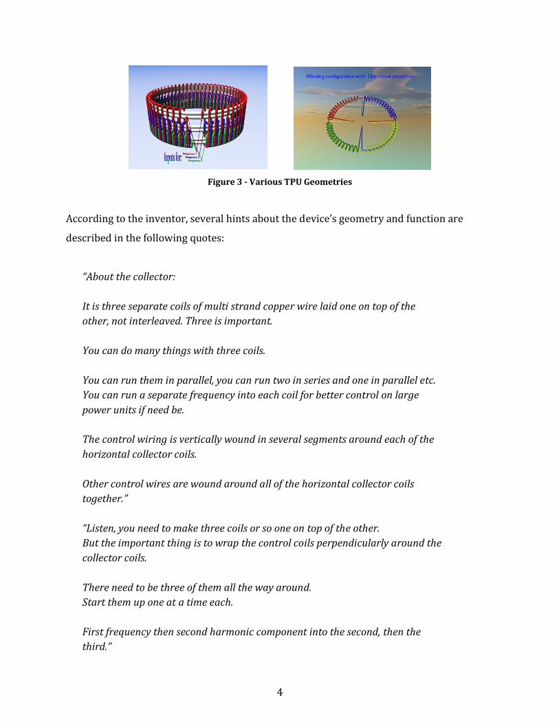
Figure 3 - Various TPU Geometries
According to the inventor, several hints about the device’s geometry and function are
described in the following quotes:
“About the collector:
It is three separate coils of multi strand copper wire laid one on top of the
other, not interleaved. Three is important.
You can do many things with three coils.
You can run them in parallel, you can run two in series and one in parallel etc.
You can run a separate frequency into each coil for better control on large
power units if need be.
The control wiring is vertically wound in several segments around each of the
horizontal collector coils.
Other control wires are wound around all of the horizontal collector coils
together.”
“Listen, you need to make three coils or so one on top of the other.
But the important thing is to wrap the control coils perpendicularly around the
collector coils.
There need to be three of them all the way around.
Start them up one at a time each.
First frequency then second harmonic component into the second, then the
third.”

5
“Has anyone ever done any research on what happens when we create a
magnetic field and revolve it faster and faster.
What changes and at what speed or frequency of the pulsed field do things
suddenly change?”
“If you had a short wire and you move the magnet across it, you would always have limited potential because the length of the wire was so short. Ok, now what if we increase the length of the wire to many miles in length , even with a very weak magnetic field moving across the wire you still have a much greater potential flow of power available. If we out it into perspective of power per inch, it may be easier to understand. If you have a small magnetic field moving across a wire 12 inches long, it can generate an electron flow equal to let’s say 1 milivolt per inch. If you move the magnetic 12 inches at the same speed , you get 12 milivolts as you transgress the 12 inches of wire. Understand that I am trying to convey a principle that you can understand for use in the future. So you have a wire 12 inches long, and you can make 12 milivolts moving a magnet across it. If you have a wire 1000 feet long and you move the same small magnetic field across the length of it, you can create much more voltage potential perhaps 12,000 milivolts let’s say. So, you have managed to generate a significant amount of electric power with a weak magnetic force. Ok, how does this help us? Where am I going with this? Suppose you have 1000 pieces of wire 12 inches long and you run the same weak magnetic field over them all at the same time……. You get the same flow of electrons. If the wires are run in series , then you will get the 12,000 milivolts etc. If you connect the wires in parallel, you will get a higher current but lower voltage. However, the power potential is the same whether you run the wires in series or parallel.”

6
3.2 Spherics Toroidal Power Unit
The so-called Spherics TPU is named from an anonymous person who was in contact with
Steven Mark during the time he developed the original TPU device. He went public and
shared some basic principles and construction details of the original TPU, along with a
more advanced version of the same device. The structure of the device is very similar in
construction to the Stefan Marinov MAGVID (discussed in a later section) as it uses a series
of circumferentially arranged solenoid coils, to produce a pulsed rotating field, along with a
set of bias windings, some going around the entire unit, along with individual bias windings
around each solenoid pulse coil.
Figure 4 - Spherics TPU

7
Figure 5 - Spherics TPU (2)

8
In this version of the TPU, there are six coils used to create the rotating field (The so-called
CCU coils). The coils, labeled SEP (Stable Aether Pattern) coils are the DC bias windings
which provide the static magnetic field for the rotating field to interact in. The pulse coils
are all arranged so that the poles all face each other while the bias fields are orthogonally
directed (into and out of the page).
Below is a quote from Spherics about the theory of operation:
“This is the way we see things:
Everything is ether. Elements are a stable pattern in the ether. The oscillation of the
ether as a whole allows the patterns to continue. It provides the energy to keep spherical
ether patterns continuing whilst allowing those spherical ether patterns to also emit
ether waves. All elements emit ether waves.
You apply a voltage across a conductor. Ether waves are propagated from both ends at
the same time. As they move through the copper the ether waves that the copper is made
from cause further strong waves to move out from copper into the ether around it, (This
is the ether shock wave), whether or not that ether is patterned into the elements of
what constitutes air.
The ether shock wave is NOT the magnetic field. The ether surrounding the copper, could
be ether patterned into air, or ether patterned into insulator, or just ether. This ether
interferes, if you like, with the shock wave, and causes subsequent ether waves to affect
the ether waves of the copper. It's a cyclical interaction that settles to a repeatable
pattern of interaction. Once the repeatable pattern is established even though you still
have the same voltage across the conductor the wave from the copper is effectively
attenuated and goes into building this repeatable pattern. PART OF the repeatable
pattern is the magnetic field. All these waves are longitudinal.
A SEP coil generates a stable repeating pattern in the ether. An ether shockwave
travelling through this pattern causes this stable repeating pattern to alter. As the shock
passes the pattern reverts but in a finite amount of time. If you send out another ether
shock before the pattern reverts completely, and from a different location, you can now
manipulate the pattern, expand the pattern, or cause the pattern to rotate around in
space. Even if this pattern does not manifest in a way that we measure as a magnetic
field, it can still interact with copper to produce a current like effect.

9
The amplitude of the shock ether wave depends on the physical amount of copper the
ether waves from both ends of the copper coil travel through and on the voltage applied
across the coil.”
3.3 Bob Boyce Toroidal Power System
The Bob Boyce Toroidal Power System (TPS) works in a very similar fashion to the above
two devices, the geometry is almost identical except that the coils are wrapped onto a
powdered iron Toroidal form rather than an air core. Bob Boyce originally came across the
concept while troubleshooting a three-phase power converter, and noticed that the output
from a large transformer was larger than the input when noise (e.g. pulses) got into the
three-phase windings. Below is a diagram of the basic configuration of the system:
Figure 6 - Bob Boyce TPS
The setup consists of a set of three or six pulse coils arranged around the Toroidal form
(called primaries in this case). The orange, circumferential winding is a DC bias winding,
used to turn the rotating planar field into a rotating vertical field. Bob also said that the DC
bias winding could produce DC output current directly when the three primaries are
pulsed in succession to produce field rotation. A secondary toroidal coil is also shown in the
right diagram, which the output can be taken from as well.
Below is a quote from Bob Boyce describing the general operation of the device:

10
“From some of the pictures of the SM device I looked at, it appears that SM used
permanent magnets oriented to provide a fixed magnetic preload bias to his device. This
would give a preset amount of angular distortion (twist) to his rotating magnetic field
(RMF). I do not know if he later went to adjustable fields in the interest of maintaining
better control.
The magnetic field from an applied DC bias allows for an adjustable amount of angular
distortion to form in the RMF. Polarity of applied DC determines the direction of angular
distortion in reference to the desired direction of RMF spin, i.e. CW or CCW (depending on
hemisphere). The strength of the DC bias field determines the extent of angular distortion
in the RMF. Essentially, the kicks are the interacting energy, while the shape of the EM
field can help to guide the overall operational characteristics. This is why so many device
configurations are possible with this type of technology, some working better than others.
Are
you wanting a mild angular distortion to keep power down and minimize control issues,
or do you want a wild angular distortion to tap massive power at the trade-off of control
stability and other possible issues? Having a RMF with angular distortion does not replace
the requirement of providing interacting kick energy with sharp, clean pulses.
Three phase, yes. The DC biasing is distributed around the core periphery. I have 2
different winding setups.
The one that incorporates DC bias into the secondary winding is one strictly for driving the
hydroxy gas systems, and it is very tame in comparison. It lacks an intense angular field
component, which makes it very mild-mannered in comparison. It is not so prone to
runaway, but lacks in total power capacity. It is like a tropical storm at best. This is the
one shared with the hydroxy gas crowd.
The one that has a separate DC bias winding can introduce a much greater angular field,
but it can be quite the beast to control. This one is like a hurricane that can turn into a
tornado at a moment’s notice. This is one that can initiate intense lightning strikes and
other nasty stuff if not kept on a VERY tight leash. Obviously, this one is not shared with
the hydroxy gas crowd.
The riskier and higher performance toroidal power system uses both the DC potential bias
and a magnetic bias.
The magnetic bias winding is wound around the outer core circumference, in the direction
of field rotation, starting from core top to core bottom. To this is applied a low voltage DC
current to apply an angular deflective distortion to the rotating magnetic field. The

11
polarity determines the direction of deflection, and applied current determines the
amount of deflection. This turns a RMF into a RMV (rotating magnetic vortex). Even
without this magnetic bias, a small amount of vortex will form in a RMF. By pushing the
vortex into more extreme distortion, more energy can be tapped, but at the expense of
stability. Be sure to feed this DC bias winding through filters to keep the HF EMF out of the
power supply.
Vortex mode, which is almost identical to rotational mode. The addition of a longitudinal
bias winding and a high enough DC bias can result in the analogy of a "severe hurricane",
or a "tornado". This is the highest energy mode, which is very unstable, and can be
extremely difficult to maintain control of.
Applied bias can play a major role in the behavior and severity of the "storm"
Oh, by the way, that longitudinal low voltage bias winding is for adding the magnetic bias,
not a low voltage DC potential bias, so it must be a fully closed winding fed with straight
DC, not pulses. That longitudinal winding is to be wound in the direction of rotation, from
top to bottom. The higher voltage DC potential bias needs to be coupled onto the
secondary, and decoupled from the load for most applications. If longitudinal DC is
required to run a load, then you can add another longitudinal winding or two to the top
and/or bottom of the core before wrapping the secondary. Be sure to follow the direction
of rotation or it will not work properly.”
3.4 Stefan Marinov Magnetic Vortex Hyper Ionization Device
The Magnetic Vortex Hyper Ionization Device (MAGVID) was promoted by physicist Stefan
Marinov, though from what I have been able to find, the originator of information on this
device was purportedly a person named Colonel James Stephens, who supposedly worked
at Groom Lake in advanced programs for the US military.
Though there are no specific claims of excess power output from the device, the general
description form James Stephens very much matches similar claims from the previous
devices mentioned earlier. However, the most informative information concerns the
interaction of the rotating and static fields in the device, which also sheds more light on the
operation and effects of high speed rotating fields. Rather than restate the information, the
relevant points (which were posted at the website, http://www.linux-
host.org/energy/magvid.htm, have been quoted verbatim on the following sub-sections.

12
3.4.1 Reported effects of Magnetic Vortex Hyper-Ionization Device
Conventional 1) Production of extreme High Voltage. 2) The rotating magnetic field spins compass needle.
Unconventional 1) EM Doppler effects. 2) Time dilation (measured from inside) with all that follows it.
- Resultant time compression of EM radiation. - Resultant decrease in perceived inertia and mass. - Resultant greater perceived acceleration with less force (measured from inside). - Resultant speed compression (low speed inside, appears as high speed outside).
3) Shielding effect on the inside by the oblate spheroids of ionized particles and electrons outside the device. Anything that comes in contact with the rotating ionization cloud would be heated and swirled.
3.4.2 The Magnetic Vortex
...The extreme electrical ionization of matter in this experiment produces many anomalous effects with many uses, i.e.: as a lightweight HV power supply, non-motional EM Doppler effects, time dilation and associated bandwidth compression in violation of the Shannon’s limit, a=F/m inertial modification, as well as spectacular visual display around the experiment (above 3 MHz).
There are three fields we can use to set up an electric vacuum inside of the experiment by pumping electrons into an external electric sheet. These are:
(1) Static magnetic fields (2) Alternating magnetic fields (3) Pulsating (PDC) magnetic fields
Let's start with classical electromagnetics point of view: Imagine a permanent magnet with North pole out of your computer monitor. Its flux lines can be imagined as a large number of X marks on your screen. An electron moves in the plane of the monitor from left to right. As the electron cuts the lines of magnetic flux, Lorentz force F = qvB deflects it downward. The electron actually spirals clockwise in the plane of the computer monitor with radius r = mv / qB, with B in Teslas and all other measures in MKSA units. If the electron came from opposite direction it would spiral same direction, or clockwise as we see it.
Lorentz force derives from static magnetic fields when there is relative motion between the magnetic field and electron. No force acts on the electron when its motion is parallel to the lines of magnetic flux. The force acts on the electron only when the magnetic flux lines are

13
cut. And this static magnetic field is conservative (performs no work). The relevant Maxwell equation here is curl E = dB/dt, and since the flux density is static here, dB/dt is zero, curl E is zero, and the field is by definition conservative. No work is done on electrons, so we deduce that the electrons spiral but maintain the same velocity and kinetic energy.
Static electrons can also be accelerated by magnetic fields. In that case curl E is nonzero and electrons must absorb energy, or must be accelerated, by the time-variant magnetic field. This case is actually the same as the above case, but as electric current changes in the coil producing the magnetic flux, this flux expands or collapses. There is still a relative motion and electrons still experience the same Lorentz force. For example, sending pulsating (PDC) instead of direct current through the same coil in the same direction causes the same spiraling effect on static electrons as the static magnetic field had on moving electrons. Sending alternating current (AC) through the coil causes periodic reversals of electrons. The field around the coil can be given by E(r,t) = 1/2pir*dP/dt, where P is flux in webers. The electric lines form concentric circles about the coil, and another way to say this is E = f * B, where f is frequency in Hz, B is average flux density of a periodic flux, and E is in volts per meter close to the coil. These three fields, static, AC, and PDC make for any manipulation of electrons inside the experiment.
Two methods exist to produce the electric sheet outside of the experiment. Both require pumping electrons from inside the experiment into a sheet of electricity outside. The first method does this from a central magnetic pole. A strong static magnetic field is set up, and PDC is sent oppositively through the pole to set up circular electric lines around it. Electrons are accelerated circularly around the pole and as soon as they move they experience an outward centrifugal deflection qvB. Each electron which leaves the center of the experiment leaves a positive electric hole, and so there is also an internal electric centripetal field F = knqq/rr, where n is the number of electrons removed to the external electric sheet. Each electron has potential energy - kq/r, and the experiment has the same potential energy, so it is electrically excited, because excitation is the only way matter absorbs electric energy without heating. Also, one may view removing an electron from an atom as "exciting it past ionization potential." The problem here is that the electrons are limited to the speed of light, and one may assume they gain light speed (or close to it) instantly in any tangible electric field (by v=Eqt/electron mass, provided that the inter- collision time is high enough). Thus speed of light acts to limit the qvB centrifugal force and so limit the power in the field to around 40 megajoules, very marginal.
The second method (shown on diagram bellow) utilizes a four-coil, two-phase ring, exactly the same as in two-phase AC motor stators. The time variant magnetic field produced by such AC motor stator arrangement is identical with a magnetic field of a real permanent magnet rotating around the axis Y in the plane XZ. Imagine such a rotating magnet in the plane of your computer monitor (plane XZ on diagram). It can be shown that the lines of rotating magnetic flux cut electrons in such a way that Lorentz force creates unidirectional electric lines through the plane of your computer monitor (plane XZ on diagram). In other words, electrons appear to be "blown through the surface of the computer monitor" just like air molecules are blown by a circular fan blade. When we add a static magnetic field (a central pole) just like in the first method (i.e.: by a solenoidial coil
14
positioned into the monitor, or along Y-axis), its magnetic lines of flux are perpendicular to the flux lines of the rotating magnetic field. As a result of this unique juxtaposition of these static and rotating magnetic fields, electrons are sucked from in front of the monitor surface, but since they are limited to the speed of light, they enter the static magnetic field only so far before assuming a circular orbit through Lorentz deflection. Electrons are pulled from inside of the experiment parallel to static flux lines and when they begin to cut the static flux lines just below the surface of your computer monitor, they spiral out to the same radius as above. Without velocity greater than light they can go no further. So light speed, once the limiting factor, now allows the field to achieve almost any energy. No energy is lost in this field except through collisions with air molecules, which effects are minimized at higher frequencies, and become nonexistent in vacuum. The density of the field is a function of solely the frequency of the magnetic vortex (rotating field) and flux density B, or in other terms: the resultant electric field strength in volts per meter. The stronger this electric field, the more electrons are stripped from inside the experiment and more dense the external electric sheet becomes. Very little energy is required at higher frequencies to produce sheets dense enough to exhibit anomalous effects.
Note: an oblate hemispheroid sheets of charge are formed outside of this experiment, which may become very dense. Anything in these hemispheres will be heated electrically. However, inside the experiment, despite powerful electric fields, the internal Joule heating is nonexistent because electrons are held outside, and the electric fields are no more dangerous than the 10 kV/m field under a thundercloud. Outside the experiment, the charge in either hemisphere rotates opposite to that in the other hemisphere. This can be seen by considering the Lorentz force. Electrons entering the static magnetic field from outside are deflected in one direction. Electrons leaving the static field from the inside are deflected in the opposite direction.
The main problem we had, was finding means for excitation without relaxation, which normally releases all stored energy in apx. 10 nanoseconds. Energy required for any significant frequency shift is enormous. Setting up a weak static magnetic field allows a sort of resonance effect, where massive amounts of energy are absorbed by the field without release. Excitation and resonance are only obtainable when relaxation is eliminated as it can be in the magnetic vortex system...

15
Figure 7 - MAGVID Coil Arrangement

16
Figure 8 - High Voltage Separation in the MAGVID

17
4. MECHANICAL ANALOG – THE HOMOPOLAR GENERATOR
The Homopolar generator is one of those enigmas of physics which has baffled many
people over the years. There are quite a few misunderstandings about its operation but
one particular quality of the device lends itself to the interests of those searching for a way
to tap environmental energy.
Figure 9 - Faraday Disk (Homopolar) Generator
The interesting thing about this device can be seen in the three possible driving conditions:
Case 1 Disk rotating and magnet(s) stationary – Potential Produced
Case 2 Disk Stationary and magnet(s) rotating – No potential Produced
Case 3 Disk and magnet(s) rotating together – Potential Produced
The homopolar disk generator’s operation is generally explained using the Lorentz force
Law, which states that a voltage is produced whenever a conductor is moved through a
magnetic field. However, it is hard to explain the cases where the magnet is moved and the
conductor is stationary (no power), or the case where the magnet and disk are moved
together (no relative motion but power produced). There is an extensive discussion on
Wikipedia about this phenomenon, titled Faraday’s Paradox, where several theoretical
explanations are offered, however, this does not change the physical reality of this effect.

18
The implications of this are more pronounced when looking at the Homopolar Motor, the
analog to the Homopolar generator.
Figure 10 - Simple Homopolar Motor Demonstration
In this simple motor, the three operating modes are even less clear, as the geometry of the
motor and the placement of the currents mainly determine it’s behavioral characteristics.
Without going into too much detail, the following set of videos give the most instructive,
hands on understanding of the motor’s behavior.
Simple homopolar motor
http://www.youtube.com/watch?v=s138-oe79_I
Example of homopolar motor with no reaction force
http://www.youtube.com/watch?v=dsHRp2z5xyk&feature=endscreen
Example of homopolar motor with reaction force against space
http://www.youtube.com/watch?v=ZbfTgGEtzg0
From these three videos, one can immediately see one clear thing. Like the Homopolar
generator, depending on how the motor is run, it can produce a torque with no reaction
force against the magnet. This lack of equal and opposite reactions are what people like
Bruce DePalma had exploited to make a generator which could produce power without
loading down its electrical source. If the same principle is applied to rotating magnetic

19
fields which produce a DC output (just like the Homopolar motor and generator, using the
Lorentz force) then the same asymmetry is probably involved in the process.
5. QUASI HOMOPOLAR GENERATOR MODEL
5.1 Thought Experiment
After investigating the above devices and principles, my goal was to connect the idea of the
Lorentz force law to electrically-produced rotating magnetic fields to see if it would be
possible to produce a DC current using such techniques. As a first thought experiment,
consider the following design.
Figure 11 - Mechanical Rotating Magnetic Field Model
In the figure above, a doughnut magnet is depicted with its north pole facing outward and
having a radius that varies in length from 2 inches to 2.5 inches. Each of the circles with x’s
in the center represent conducting wires that are 1 inch long facing out of the page. In this
example, this design is meant to emulate the effect of a rotating magnetic field with a bias
applied.
20
To give a further explanation for this configuration, consider the following.
In order to induce current in the conducting wires via the motional EMF (Lorentz force
induction), the wires need to be in motion through a magnetic field that does not exhibit
any polarity reversals (to produce a DC potential). However, in the devices which use
rotating magnetic fields, there is no physical rotary motion of the coils. In order to produce
the DC output via the Lorentz force induction, the field must move rather than the coils.
However, we have seen from the example of the Homopolar generator that rotating the
magnet while the disk remains stationary results in no output.
Some have stated that the disk of the Homopolar generator needs to perceive a state of
motion through space in order for the EMF to manifest. The magnet moving alone does not
seem to provide this condition. However, it is known that spinning a rotating magnetic field
also creates a perceived spin in the space around the field (a separate frame of reference as
some sources have identified). However, a more complex field structure is apparently
required.
If one subscribes to the description given for the MAGVID, Col. James Stephens explains
that modulating the magnitude of a static magnetic field will stimulate the space around the
device, much like a Cyclotron uses modulated electric fields to set free electrons into
motion. All of the described devices used either AC or pulsed DC to stimulate the DC bias
field; so in this thought experiment, the varying radius of the permanent magnet is used to
create the appearance of a time varying (but not polarity reversing) magnetic field.
However, once we introduce a time-varying magnetic field into the system, we also need to
take into account the effects of the transformer EMF (standard induction), which will
induce an alternating voltage into the wires due to the changing magnetic field intensity.
One goal of this thought experiment is to determine how much (if any) DC current would
appear using this arrangement? Also, what would be the ratio of the emf’s induced by the
motional vs. transformer EMFs?

21
5.2 Simplified Model
TBD
Top Related