

![S4F STRIVE FITNESS REQUIRMENT COLLECTION... contact@credofy.com +91-9711054188 [Kindly contact us to get the trial link of the royalty free stock image website]](https://static.fdocuments.in/doc/165x107/5f0380687e708231d40960f8/s4f-strive-fitness-requirment-contactcredofycom-91-9711054188-kindly-contact.jpg)


Languages
Pages
Legal

������������������������������������������������������������������������������������
Quality of product
Without well written document
-- Developers do not know what to build
-- Customers do not know what to expect
-- What to validate
Requirements describe
What not How
Produces one large document written in natural language contains a description of what the system will do without
describing how it will do it.
Process that creates it
Crucial process steps
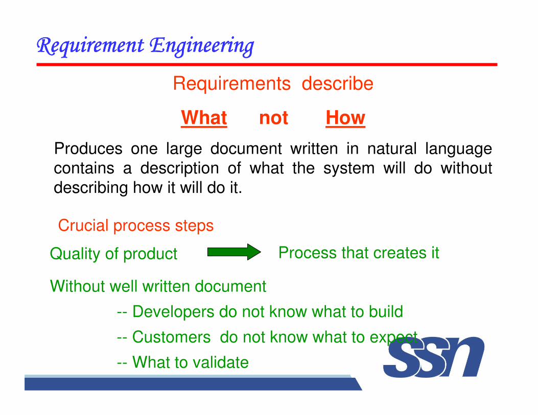
Requirement
Engineering
Requirements
Elicitation
Requirements
Analysis
Requirements
Documentation
Requirements
Review
Problem Statement
SRS
Crucial Process Steps of requirement engineering
������������������������������������������������������������������������������������
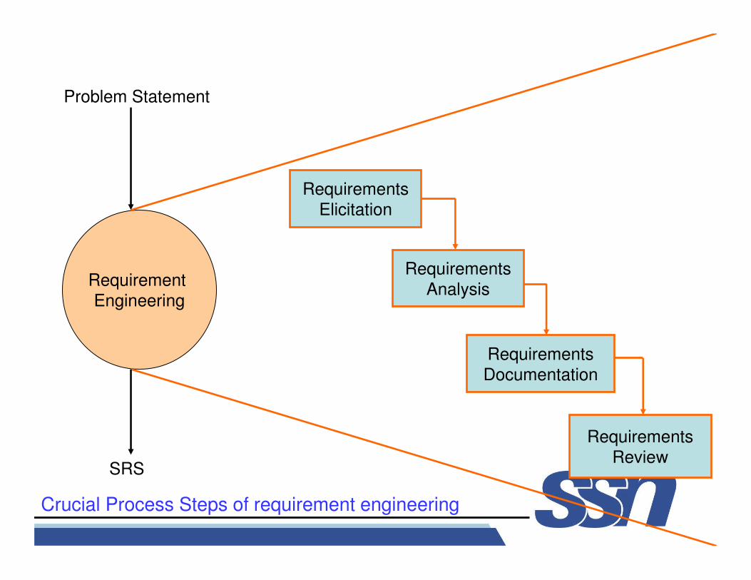
Requirement Engineering is the disciplined application of proven principles, methods, tools, and notations to describe a
proposed system’s intended behavior and its associated
constraints.
SRS may act as a contract between developer and customer.
State of practice
Requirements are difficult to uncover
• Requirements change
• Over reliance on CASE Tools
• Tight project Schedule
• Communication barriers
• Market driven software development
• Lack of resources
Example
A University wish to develop a software system for the
student result management of its M.Tech. Programme. A
problem statement is to be prepared for the software
development company. The problem statement may give
an overview of the existing system and broad expectations
from the new software system.
������������������������������������������������������������������������������������
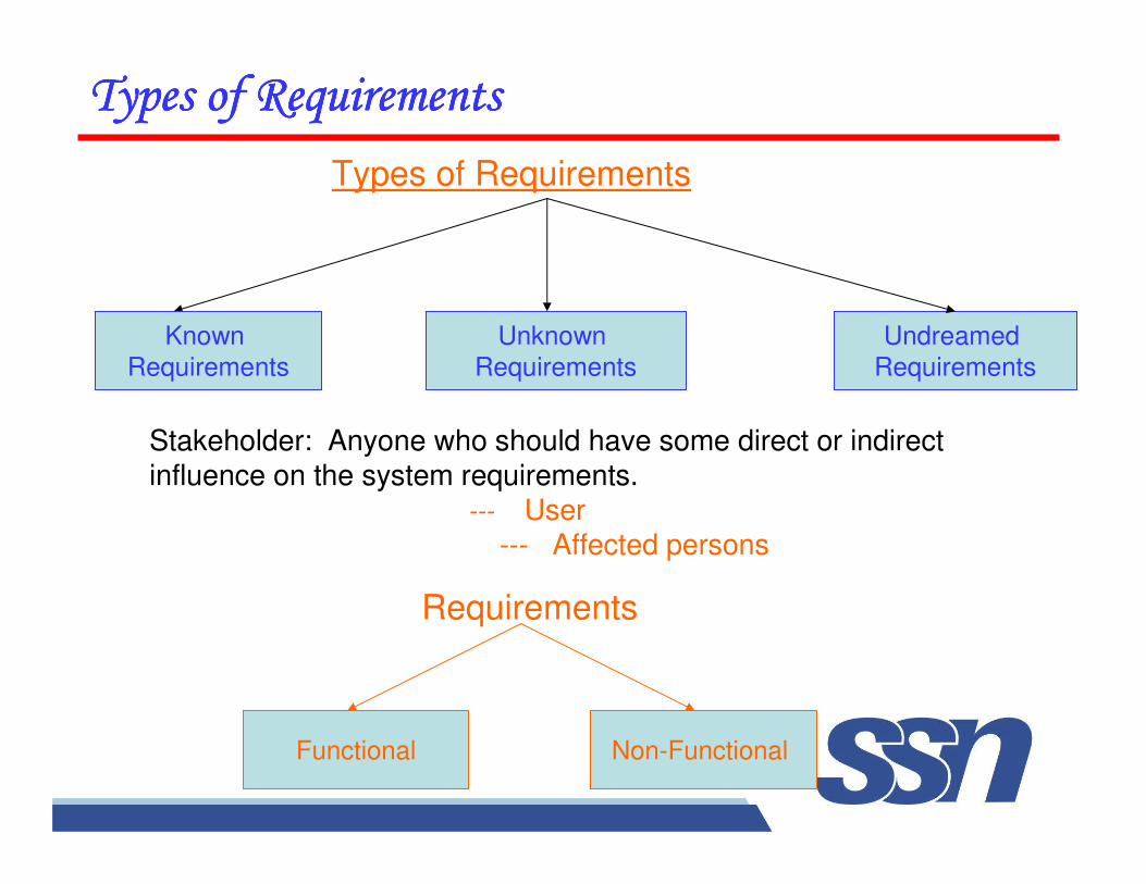
Types of Requirements
Known
Requirements
Undreamed
Requirements
Unknown
Requirements
Stakeholder: Anyone who should have some direct or indirect influence on the system requirements.
--- User--- Affected persons
Requirements
Functional Non-Functional
����������������� ����������������� ����������������� �����������������
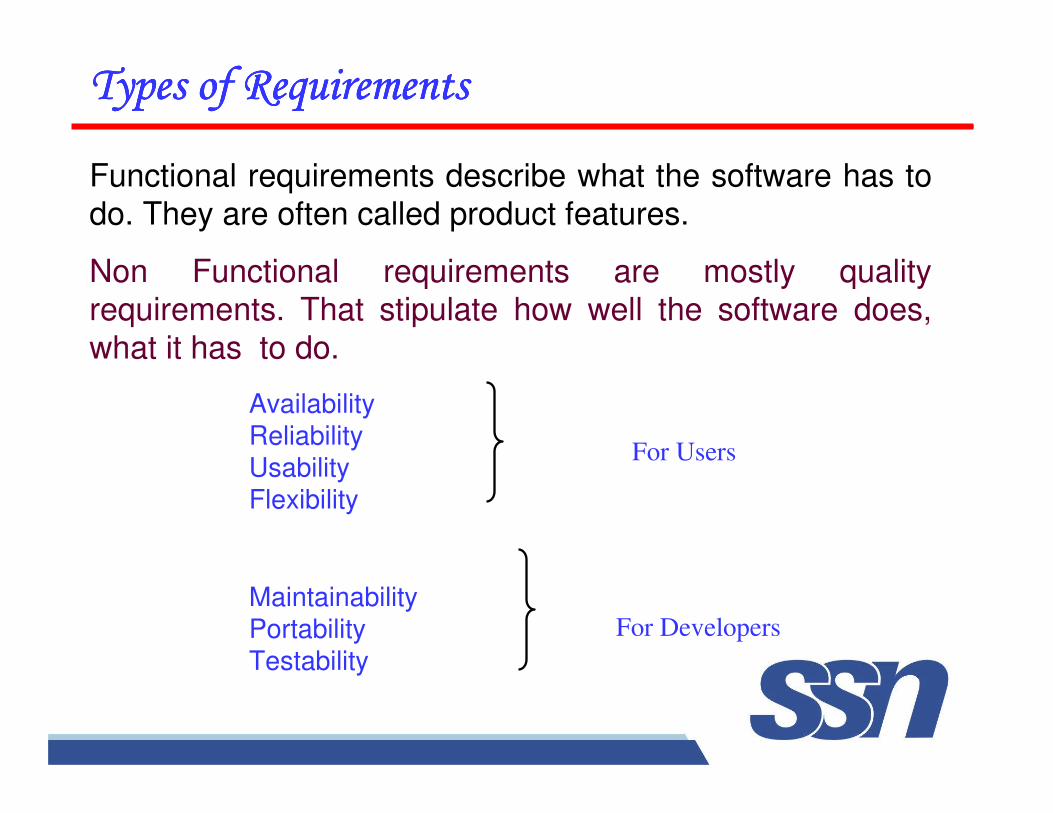
MaintainabilityPortabilityTestability
For Users
For Developers
����������������� ����������������� ����������������� �����������������
Functional requirements describe what the software has to do. They are often called product features.
Non Functional requirements are mostly quality requirements. That stipulate how well the software does,
what it has to do.
AvailabilityReliabilityUsabilityFlexibility
������������������� !�������
" ����� ��� !������� ���� #�!����� $%�� �&�� ����� ����!�'( ��� $ �'�!%��(� ���� �%�� $ �'�!%��(���� !�������
" ������ ��� !������� ���� ���!)��� $�%�� ������� !��������
" �&�� ���� � ������� ��� !�������� ���� �&�� *����� %$��%$�#���� ��� !������� ���� �*�'!$!'��!%�� + � ,��%' �����
����������������� ����������������� ����������������� �����������������
����������������� ����������������� ����������������� �����������������
Interface Specification
• Important for the customers.
TYPES OF INTERFACES
• Procedural interfaces (also called Application
Programming Interfaces (APIs)).
• Data structures
• Representation of data.
��������������������������������������������������������
Is cancellation of a project a bad news?
As per IBM report, “31% projects get cancelled before they are completed, 53% over-run their cost estimates by an
average of 189% & for every 100 projects, there are 94
restarts.
How do we cancel a project with the least work?
CONDUCT A FEASIBILTY STUDY
��������������������������������������������������������
Technical feasibility
• Is it technically feasible to provide direct communication connectivity through space from one location of globe to
another location?
• Is it technically feasible to design a programming language using “Sanskrit”?
��������������������������������������������������������
Feasibility depends upon non technical Issues like:
• Are the project’s cost and schedule assumption realistic?
• Does the business model realistic?
• Is there any market for the product?
��������������������������������������������������������
Purpose of feasibility study
“evaluation or analysis of the potential impact of a
proposed project or program.”
Focus of feasibility studies
• Is the product concept viable?
• Will it be possible to develop a product that matches the
project’s vision statement?
• What are the current estimated cost and schedule for the
project?
��������������������������������������������������������
Focus of feasibility studies
• How big is the gap between the original cost & schedule
targets & current estimates?
• Is the business model for software justified when the
current cost & schedule estimate are considered?
• Have the major risks to the project been identified & can
they be surmounted?
• Is the specifications complete & stable enough to support remaining development work?
��������������������������������������������������������
Focus of feasibility studies
• Have users & developers been able to agree on a
detailed user interface prototype? If not, are the requirements really stable?
• Is the software development plan complete & adequate to support further development work?
Perhaps
• Most difficult
• Most critical• Most error prone
• Most communication intensive
Succeed
��������������������������������������������������������������������������������
Selection of any method
1. It is the only method that we know
2. It is our favorite method for all situations
3. We understand intuitively that the method is effective in the present circumstances.
Normally we rely on first two reasons.
effective customer developer partnership
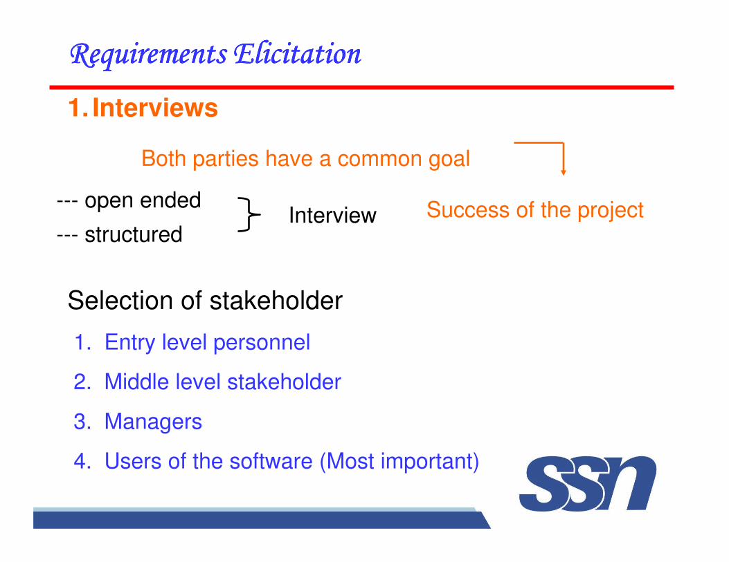
1. Interviews
Both parties have a common goal
Interview
��������������������������������������������������������������������������������
Selection of stakeholder
1. Entry level personnel
2. Middle level stakeholder
3. Managers
4. Users of the software (Most important)
Success of the project--- open ended
--- structured
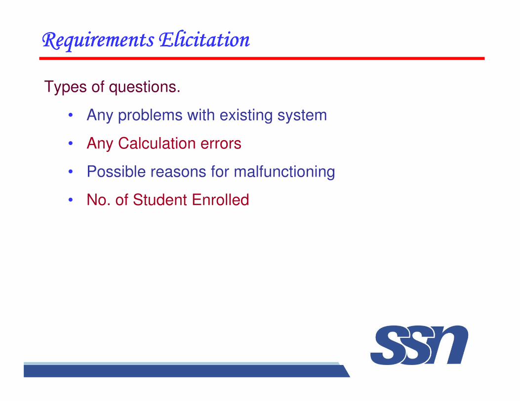
Types of questions.
• Any problems with existing system
• Any Calculation errors
• Possible reasons for malfunctioning
• No. of Student Enrolled
��������������������������������������������������������������������������������
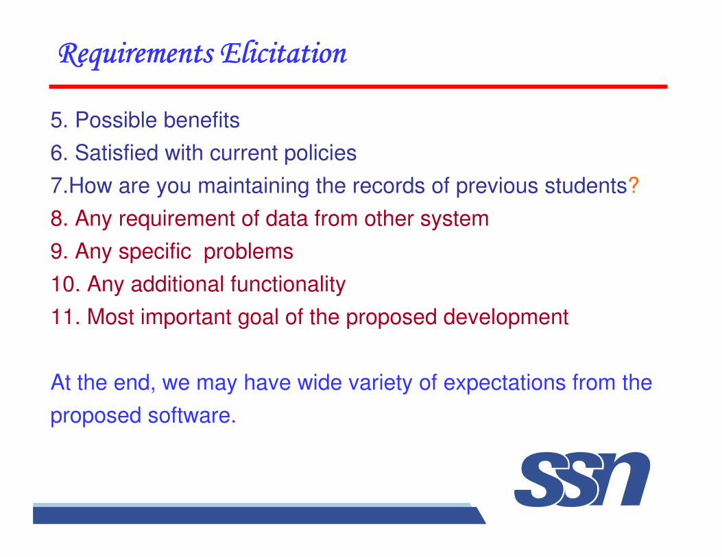
5. Possible benefits
6. Satisfied with current policies
7.How are you maintaining the records of previous students?
8. Any requirement of data from other system
9. Any specific problems
10. Any additional functionality
11. Most important goal of the proposed development
At the end, we may have wide variety of expectations from the
proposed software.
��������������������������������������������������������������������������������
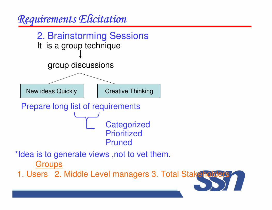
2. Brainstorming SessionsIt is a group technique
Creative ThinkingNew ideas Quickly
��������������������������������������������������������������������������������
*Idea is to generate views ,not to vet them.
Groups
1. Users 2. Middle Level managers 3. Total Stakeholders
Categorized PrioritizedPruned
Prepare long list of requirements
group discussions
A Facilitator may handle group bias, conflicts carefully.
-- Facilitator may follow a published agenda
-- Every idea will be documented in a way that everyone can see it.
--A detailed report is prepared.
3. Facilitated Application specification Techniques (FAST)
-- Similar to brainstorming sessions.
-- Team oriented approach
-- Creation of joint team of customers and developers.
��������������������������������������������������������������������������������
Guidelines
1. Arrange a meeting at a neutral site.
2. Establish rules for participation.
3. Informal agenda to encourage free flow of ideas.
4. Appoint a facilitator.
5. Prepare definition mechanism board, worksheets, wall
stickier.
6. Participants should not criticize or debate.
FAST session PreparationsEach attendee is asked to make a list of objects that are:
�������������������������������������������� ������������������������������������

1. Part of environment that surrounds the system.
2. Produced by the system.
3. Used by the system.A. List of constraints
B. Functions
C. Performance criteria
Activities of FAST session
1. Every participant presents his/her list
2. Combine list for each topic
3. Discussion
4. Consensus list
5. Sub teams for mini specifications
6. Presentations of mini-specifications
7. Validation criteria
8. A sub team to draft specifications
��������������������������������������������������������������������������������
4.Quality Function Deployment
-- Incorporate voice of the customer
��������������������������������������������������������������������������������
-- Normal requirements
-- Expected requirements
-- Exciting requirements
What is important for customer?
Prime concern is customer satisfactionDocumented
Technical requirements.
Steps
1. Identify stakeholders
2. List out requirements
3. Degree of importance to each requirement.
��������������������������������������������������������������������������������
5 Points : V. Important
4 Points : Important
3 Points : Not Important but nice to have
2 Points : Not important
1 Points : Unrealistic, required further
exploration
Requirement Engineer may categorize like:
(i) It is possible to achieve
(ii) It should be deferred & Why
(iii) It is impossible and should be dropped from consideration
First Category requirements will be implemented as per
priority assigned with every requirement.
��������������������������������������������������������������������������������
5. The Use Case Approach
Ivar Jacobson & others introduced Use Case approach for elicitation & modeling.
Use Case – give functional view
The terms
Use Case
Use Case Scenario
Use Case Diagram
��������������������������������������������������������������������������������
Use Cases are structured outline or template for the description of user requirements modeled in a structured language like English.
Often Interchanged
But they are different
Use case Scenarios are unstructured descriptions of user requirements.
Use case diagrams are graphical representations that
may be decomposed into further levels of abstraction.
Components of Use Case approach
Actor:
An actor or external agent, lies outside the system model, but interacts with it in some way.
Actor
��������������������������������������������������������������������������������
Person, machine, information System
• Cockburn distinguishes between Primary and secondary actors.
• A Primary actor is one having a goal requiring the assistance of the system.
• A Secondary actor is one from which System needs assistance.
Use Cases
A use case is initiated by a user with a particular goal in mind, and completes successfully when that goal is satisfied.
��������������������������������������������������������������������������������
* It describes the sequence of interactions between actors and the system necessary to deliver the services that
satisfies the goal.
* Alternate sequence
* System is treated as black box.
Thus
Use Case captures who (actor) does what (interaction) with the system, for what purpose (goal), without dealing
with system internals.
��������������������������������������������������������������������������������
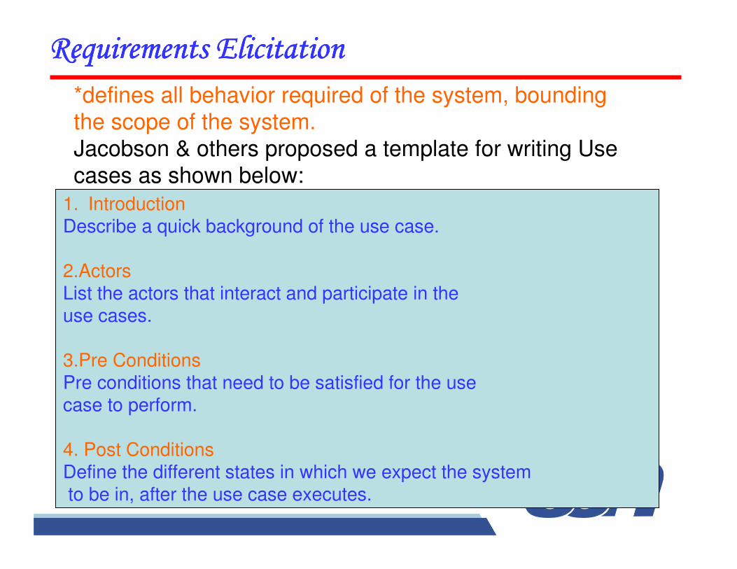
*defines all behavior required of the system, bounding the scope of the system.
Jacobson & others proposed a template for writing Use
cases as shown below:
1. IntroductionDescribe a quick background of the use case.
2.ActorsList the actors that interact and participate in the use cases.
3.Pre ConditionsPre conditions that need to be satisfied for the use case to perform.
4. Post ConditionsDefine the different states in which we expect the systemto be in, after the use case executes.
��������������������������������������������������������������������������������
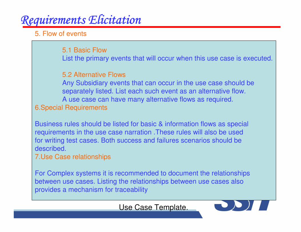
5. Flow of events
5.1 Basic Flow
List the primary events that will occur when this use case is executed.
5.2 Alternative Flows
Any Subsidiary events that can occur in the use case should be
separately listed. List each such event as an alternative flow.
A use case can have many alternative flows as required.
6.Special Requirements
Business rules should be listed for basic & information flows as special
requirements in the use case narration .These rules will also be used
for writing test cases. Both success and failures scenarios should be
described.
7.Use Case relationships
For Complex systems it is recommended to document the relationships
between use cases. Listing the relationships between use cases also
provides a mechanism for traceability
Use Case Template.
��������������������������������������������������������������������������������
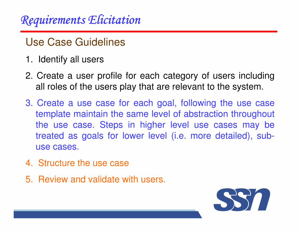
Use Case Guidelines
1. Identify all users
2. Create a user profile for each category of users including
all roles of the users play that are relevant to the system.
3. Create a use case for each goal, following the use case
template maintain the same level of abstraction throughout the use case. Steps in higher level use cases may be
treated as goals for lower level (i.e. more detailed), sub-use cases.
4. Structure the use case
5. Review and validate with users.
��������������������������������������������������������������������������������
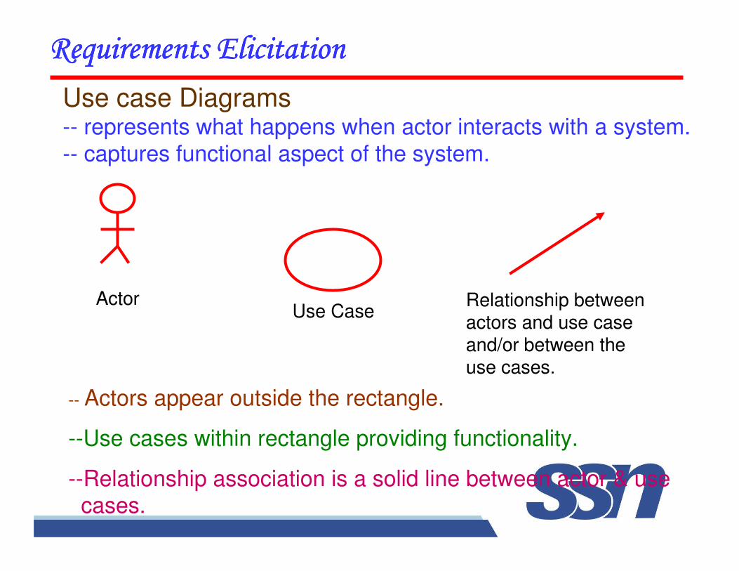
Use case Diagrams-- represents what happens when actor interacts with a system.
-- captures functional aspect of the system.
Use CaseRelationship betweenactors and use case and/or between the use cases.
��������������������������������������������������������������������������������
-- Actors appear outside the rectangle.
--Use cases within rectangle providing functionality.
--Relationship association is a solid line between actor & use cases.
Actor
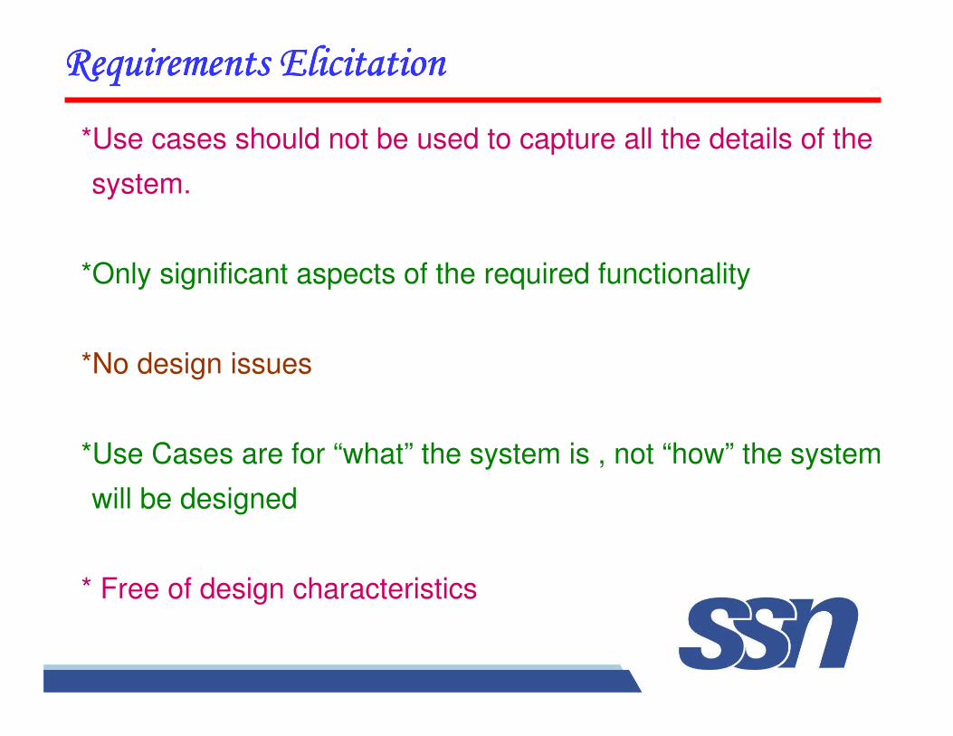
*Use cases should not be used to capture all the details of the
system.
*Only significant aspects of the required functionality
*No design issues
*Use Cases are for “what” the system is , not “how” the system
will be designed
* Free of design characteristics
�������������������������������������������� ������������������������������������
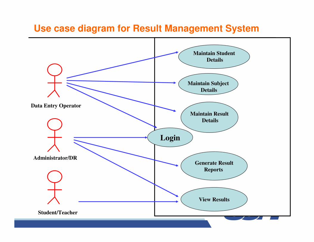
Use case diagram for Result Management System
Maintain Student
Details
Maintain Subject
Details
Maintain Result
Details
Login
Generate Result
Reports
View Results
Data Entry Operator
Administrator/DR
Student/Teacher
1. Maintain student Details
Add/Modify/update students details like name, address.
2.Maintain subject Details
Add/Modify/Update Subject information semester wise
3.Maintain Result Details
Include entry of marks and assignment of credit points for each paper.
4. Login
Use to Provide way to enter through user id & password.
5. Generate Result Report
Use to print various reports
6. View Result(i) According to course code(ii) According to Enrollment number/roll number
��������������������������������������������������������������������������������
Login
1.1 Introduction : This use case describes how a user logs into
the Result Management System.
1.2 Actors : (i) Data Entry Operator
(ii) Administrator/Deputy Registrar
1.3 Pre Conditions : None
1.4 Post Conditions : If the use case is successful, the actor is
logged into the system. If not, the system state is unchanged.
��������������������������������������������������������������������������������������������������������������������
��������������������������������������������������������������������������������������������������������������������
1.5 Basic Flow : This use case starts when the actor wishes
to login to the Result Management system.
(i) System requests that the actor enter his/her name and
password.
(ii) The actor enters his/her name & password.
(iii) System validates name & password, and if finds correct
allow the actor to logs into the system.
1.6 Alternate Flows
1.6.1 Invalid name & passwordIf in the basic flow, the actor enters an invalid name
and/or password, the system displays an error message. The actor can choose to either return to the beginning of the basic flow or cancel the login, at that point, the use case ends.
1.7 Special Requirements:
None
1.8 Use case Relationships:
None
��������������������������������
2.Maintain student details
2.1 Introduction : Allow DEO to maintain student details.
This includes adding, changing and deleting student
information
2.2 Actors : DEO
2.3 Pre-Conditions: DEO must be logged onto the
system before this use case begins.
��������������������������������
2.4 Post-conditions : If use case is successful, student
information is added/updated/deleted from the system.
Otherwise, the system state is unchanged.
2.5 Basic Flow : Starts when DEO wishes to
add/modify/update/delete Student information.
(i) The system requests the DEO to specify the function,
he/she would like to perform (Add/update/delete)
(ii) One of the sub flow will execute after getting the
information.
��������������������������������
� If DEO selects "Add a student", "Add a student" sub flow willbe executed.
� If DEO selects "update a student", "update a student" sub flow will be executed.
� If DEO selects "delete a student", "delete a student" sub flow will be executed.
2.5.1 Add a student(i) The system requests the DEO to enter:
NameAddressRoll NoPhone NoDate of admission
(ii) System generates unique id
��������������������������������
��������������������������������
2.5.2 Update a student
(i) System requires the DEO to enter student-id.
(ii) DEO enters the student_id. The system retrieves and
display the student information.
(iii) DEO makes the desired changes to the student
information.
(iv) After changes, the system updates the student record with changed information.
2.5.3 Delete a student
(i) The system requests the DEO to specify the student-id.
(ii) DEO enters the student-id. The system retrieves and displays the student information.
(iii) The system prompts the DEO to confirm the deletion of the student.
(iv) The DEO confirms the deletion.
(v) The system marks the student record for deletion.
��������������������������������
��������������������������������
2.6 Alternative flows
2.6.1 Student not found
If in the update a student or delete a student sub flows,
a student with specified_id does not exist, the system
displays an error message .The DEO may enter a
different id or cancel the operation. At this point ,Use
case ends.
��������������������������������
2.6.2 Update Cancelled
If in the update a student sub-flow, the data entry
operator decides not to update the student information,
the update is cancelled and the basic flow is restarted at
the begin.
2.6.3 Delete cancelled
If in the delete a student sub flows, DEO decides not to
delete student record ,the delete is cancelled and the
basic flow is re-started at the beginning.
2.7 Special requirements
None
2.8 Use case relationships
None
��������������������������������
3. Maintain Subject Details
3.1 Introduction
The DEO to maintain subject information. This includes
adding, changing, deleting subject information from the
system
3.2 Actors : DEO
3.3 Preconditions : DEO must be logged onto the
system before the use case begins.
��������������������������������
��������������������������������
3.4 Post conditions :
If the use case is successful, the subject information is added, updated, or deleted from the system,
otherwise the system state is unchanged.
3.5 Basic flows :
The use case starts when DEO wishes to add, change,
and/or delete subject information from the system.
(i) The system requests DEO to specify the function he/she
would like to perform i.e. • Add a subject
• Update a subject• Delete a subject.
(ii) Once the DEO provides the required information, one of the sub
flows is executed.
� If DEO selected “Add a subject” the “Add-a subject sub flow
is executed.
� If DEO selected “Update-a subject” the “update-a- subject”
sub flow is executed
� If DEO selected “Delete- a- subject”, the “Delete-a-subject”
sub flow is executed.
3.5.1 Add a Subject
(i) The System requests the DEO to enter the
subject information. This includes :
* Name of the subject
��������������������������������
��������������������������������
* Subject Code* Semester
* Credit points
(ii) Once DEO provides the requested information,
the system generates and assigns a unique subject-id to the subject. The subject is added to the system.
(iii) The system provides the DEO with new
subject-id.
3.5.2 Update a Subject
(i) The system requests the DEO to enter subject_id.
(ii) DEO enters the subject_id. The system retrieves and displays the subject information.
(iii) DEO makes the changes.
(iv) Record is updated.
��������������������������������
3.5.3 Delete a Subject
(i) Entry of subject_id.
(ii) After this, system retrieves & displays subject information.
* System prompts the DEO to confirm the deletion.
* DEO verifies the deletion.
* The system marks the subject record for deletion.
��������������������������������
3.6 Alternative Flow
3.6.1 Subject not found
If in any sub flows, subject-id not found, error message is
displayed. The DEO may enter a different id or cancel the
case ends here.
3.6.2 Update Cancelled
If in the update a subject sub-flow, the data entry operator
decides not to update the subject information, the update is
cancelled and the basic flow is restarted at the begin.
��������������������������������
��������������������������������
3.6.3 Delete Cancellation
If in delete-a-subject sub flow, the DEO decides not to
delete subject, the delete is cancelled, and the basic flow is restarted from the beginning.
3.7 Special Requirements:
None
3.8 Use Case-relationships
None
4. Maintain Result Details
4.1 Introduction
This use case allows the DEO to maintain subject &
marks information of each student. This includes adding
and/or deleting subject and marks information from the system.
4.2 Actor
DEO
��������������������������������
��������������������������������
4.3 Pre Conditions
DEO must be logged onto the system.
4.4 Post Conditions
If use case is successful ,marks information is
added or deleted from the system. Otherwise, the system state is unchanged.
4.5 Basic Flow
This use case starts, when the DEO wishes to add, update and/or delete marks from the system.
(i) DEO to specify the function
(ii) Once DEO provides the information one of the subflow is executed.
* If DEO selected “Add Marks “, the Add marks subflow is executed.
* If DEO selected “Update Marks”, the update marks subflow is executed.
* If DEO selected “Delete Marks”, the delete marks subflow is executed.
��������������������������������
4.5.1 Add Marks Records
Add marks information .This includes:
a. Selecting a subject code.
b. Selecting the student enrollment number.
c. Entering internal/external marks for that subject code &
enrollment number.
��������������������������������
(ii) If DEO tries to enter marks for the same combination of subject and enrollment number,the system gives a message
that the marks have already been entered.
(iii) Each record is assigned a unique result_id.
4.5.2 Delete Marks records1. DEO makes the following entries:
a. Selecting subject for which marks have to be
deleted.
b. Selecting student enrollment number.
c. Displays the record with id number.
d. Verify the deletion.
e. Delete the record.
��������������������������������
4.5.2 Update Marks records
1. The System requests DEO to enter the
record_id.
2. DEO enters record_id. The system retrieves &
displays the information.
3. DEO makes changes.
4. Record is updated.
��������������������������������
4.5.3 Compute Result(i) Once the marks are entered, result is computed
for each student.
(ii) If a student has scored more than 50% in a subject, the associated credit points are allotted to that
student.(iii) The result is displayed with subject-code, marks
& credit points.
4.6 Alternative Flow
4.6.1 Record not foundIf in update or delete marks sub flows, marks
with specified id number do not exist, the system displays an error message. DEO can enter another id or cancel the
operation.
��������������������������������
��������������������������������
4.6.2 Delete Cancelled
If in Delete Marks, DEO decides not to delete marks,
the delete is cancelled and basic flow is re-started at the beginning.
4.7 Special Requirements
None
4.8 Use case relationships
None
5 View/Display result
5.1 Introduction
This use case allows the student/Teacher or anyone
to view the result. The result can be viewed on the basis of course code and/or enrollment number.
5.2 Actors
Administrator/DR, Teacher/Student
5.3 Pre Conditions
None
5.4 Post Conditions
If use case is successful, the marks information is
displayed by the system. Otherwise, state is unchanged.
��������������������������������
5.5 Basic Flow
Use case begins when student, teacher or any other person wish to view the result.
Two ways
-- Enrollment no.
-- Course code
��������������������������������
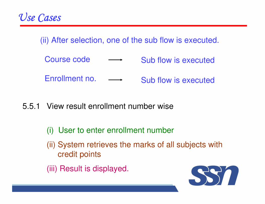
(ii) After selection, one of the sub flow is executed.
Course code
Enrollment no.
��������������������������������
5.5.1 View result enrollment number wise
(i) User to enter enrollment number
(ii) System retrieves the marks of all subjects with
credit points
(iii) Result is displayed.
Sub flow is executed
Sub flow is executed
��������������������������������
5.6 Alternative Flow
5.6.1 Record not found
Error message should be displayed.
5.7 Special Requirements
None
5.8 Use Case relationships
None
6. Generate Report
6.1 Introduction
This use case allows the DR to generate result
reports. Options are
a. Course code wise
b. Semester wisec. Enrollment Number wise
6.2 Actors
DR
6.3 Pre-ConditionsDR must logged on to the system
��������������������������������
��������������������������������
6.4 Post conditions
If use case is successful, desired report is
generated. Otherwise, the system state isunchanged.
6.5 Basic Flow
The use case starts, when DR wish to generate
reports.
(i) DR selects option.
(ii) System retrieves the information displays.
(iii) DR takes printed reports.
6.6 Alternative Flows
6.6.1 Record not found
If not found, system generates appropriate message. The DR can select another option or cancel the
operation. At this point, the use case ends.
6.7 Special Requirements
None
6.8 Use case relationships
None
��������������������������������
��������������������������������
7. Maintain User Accounts
7.1 Introduction
This use case allows the administrator to maintain
user account. This includes adding, changing and
deleting user account information from the system.
7.2 ActorsAdministrator
7.3 Pre-ConditionsThe administrator must be logged on to the
system before the use case begins.
��������������������������������
7.4 Post-Conditions
If the use case was successful, the user account information
is added, updated, or deleted from the system. Otherwise, the
system state is unchanged.
7.5 Basic Flow
This use case starts when the Administrator wishes to add,
change, and/or delete use account information from the system.
(i) The system requests that the Administrator specify the
function he/she would like to perform (either Add a User
Account, Update a User Account, or Delete a User Account).
(ii) Once the Administrator provides the requested information, one of the sub-flows is executed
��������������������������������
* If the Administrator selected “Add a User Account”, the
Add a User Account sub flow is executed.
* If the Administrator selected “Update a User Account”, the
Update a User Account sub-flow is executed.
* If the Administrator selected “Delete a User Account”, the
Delete a User Account sub-flow is executed.22
7.5.1 Add a User Account
1. The system requests that the Administrator enters the user
information. This includes:
(a) User Name
(b) User ID-should be unique for each user account
(c) Password
(d) Role
.
2. Once the Administrator provides the requested information, the
user account information is added.
7.5.2 Update a User Account
1. The system requests that the Administrator enters the User ID.
2. The Administrator enters the User ID. The system retrieves and
displays the user account information.
3. The Administrator makes the desired changes to the user
account information. This includes any of the information
specified in the Add a User Account sub-flow.
4. Once the Administrator updates the necessary information, the
system updates the user account record with the updated
information.
��������������������������������
��������������������������������
7.5.3 Delete a User Account
1. The system requests that the Administrator enters
the User ID.
2. The Administrator enters the User ID. The system
retrieves and displays the user account information.
3. The system prompts the Administrator to confirm
the deletion of the user account.
4. The Administrator confirms the deletion.
5. The system deletes the user account record.
��������������������������������
7.6 Alternative Flows
7.6.1 User Not Found
If in the Update a User Account or Delete a User Account sub-flows, a user account with the specified
User ID does not exist, the system displays an error message. The Administrator can then enter a
different User ID or cancel the operation, at which point
the use case ends.
7.6.2 Update Cancelled
If in the Update a User Account sub-flow, the
Administrator decides not to update the user account
information, the update is cancelled and the Basic Flow is re-started at the beginning.
��������������������������������
7.6.3 Delete Cancelled
If in the Delete a User Account sub-flow, the
Administrator decides not to delete the user account information, the delete is cancelled and the Basic Flow is re-started at the beginning.
7.7 Special RequirementsNone
7.8 Use case relationshipsNone
��������������������������������
8. Reset System
8.1 Introduction
This use case allows the allows the administrator to
reset the system by deleting all existing information from
the system .
8.2 ActorsAdministrator
8.3 Pre-Conditions
The administrator must be logged on to the system
before the use case begins.
��������������������������������
8.4 Post-ConditionsIf the use case was successful, all the existing
information is deleted from the backend database of
the system. Otherwise, the system state is unchanged.
8.5 Basic FlowThis use case starts when the Administrator wishes to
reset the system.
i. The system requests the Administrator to confirm if
he/she wants to delete all the existing information from the system.
ii. Once the Administrator provides confirmation, the system deletes all the existing information from the
backend database and displays an appropriate
message.
��������������������������������
8.6 Alternative Flows
8.6.1 Reset Cancelled
If in the Basic Flow, the Administrator decides
not to delete the entire existing information, the reset is
cancelled and the use case ends.
8.7 Special Requirements
None
8.8 Use case relationships
None
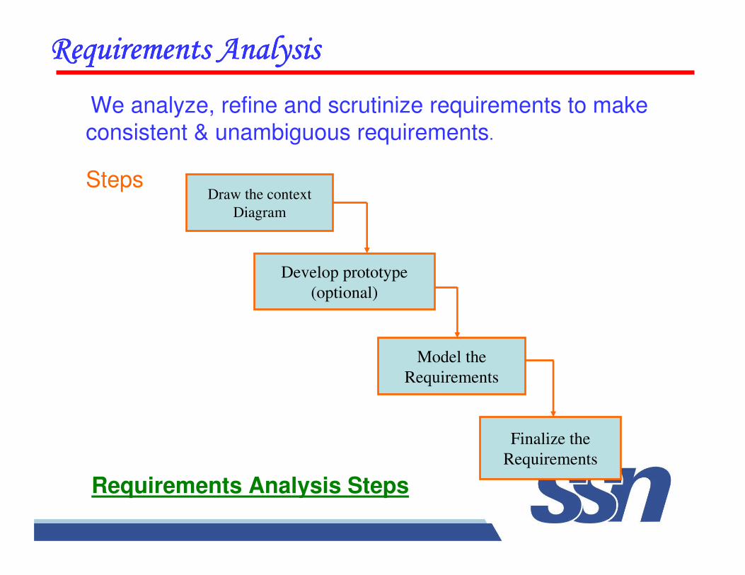
We analyze, refine and scrutinize requirements to make
consistent & unambiguous requirements.
Steps
����������������������������������������������������������������������������
Draw the context
Diagram
Develop prototype
(optional)
Model the
Requirements
Finalize the
Requirements
Requirements Analysis Steps
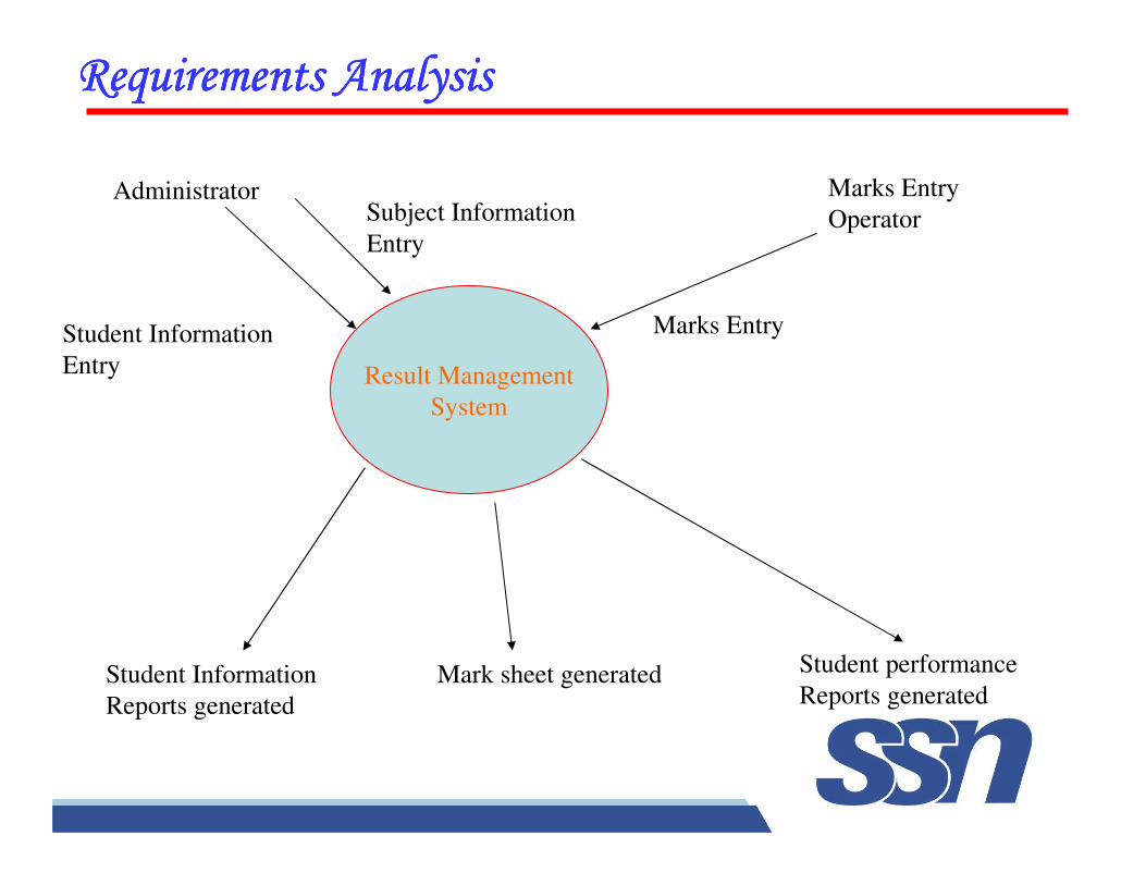
Result Management
System
Administrator Marks Entry
Operator
Student Information
Reports generated
Mark sheet generated Student performance
Reports generated
Subject Information
Entry
Student Information
Entry
Marks Entry
����������������������������������������������������������������������������
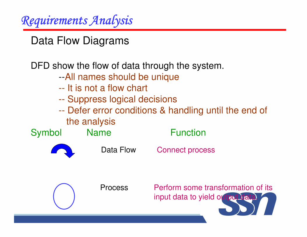
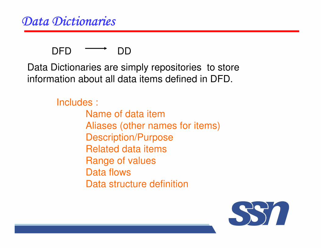
Data Flow Diagrams
DFD show the flow of data through the system.
--All names should be unique-- It is not a flow chart
-- Suppress logical decisions
-- Defer error conditions & handling until the end of the analysis
Symbol Name Function
����������������������������������������������������������������������������
Data Flow Connect process
Process Perform some transformation of its input data to yield output data.
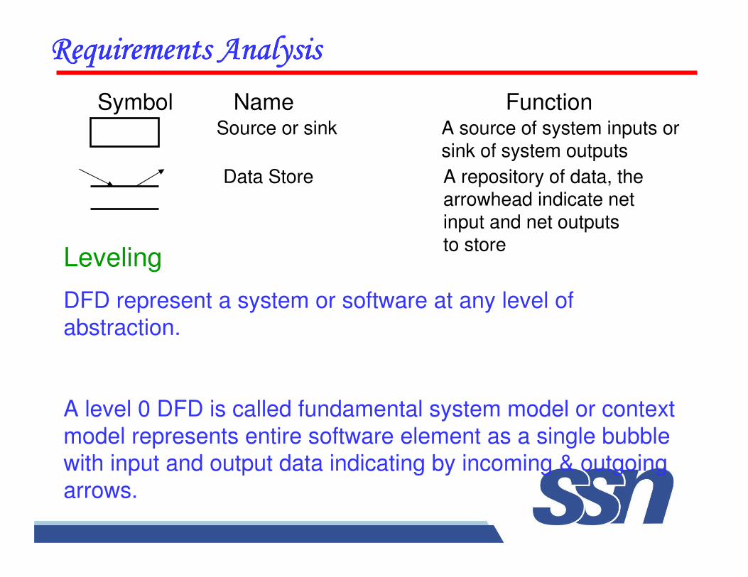
Data Store A repository of data, the arrowhead indicate netinput and net outputsto store
Source or sink A source of system inputs or sink of system outputs
����������������������������������������������������������������������������
Leveling
DFD represent a system or software at any level of abstraction.
A level 0 DFD is called fundamental system model or context
model represents entire software element as a single bubble with input and output data indicating by incoming & outgoing
arrows.
Symbol Name Function
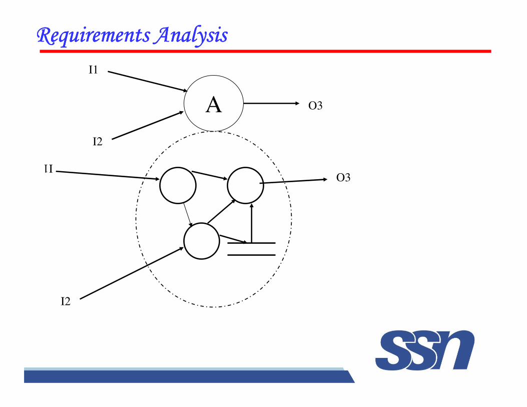
A
����������������������������������������������������������������������������
I1
I2
O3
O3
I1
I2
��������������������������������������������������������
Data Dictionaries are simply repositories to store
information about all data items defined in DFD.
Includes :Name of data item
Aliases (other names for items)
Description/Purpose Related data items
Range of valuesData flows
Data structure definition
DDDFD
��������������������������������������������������������
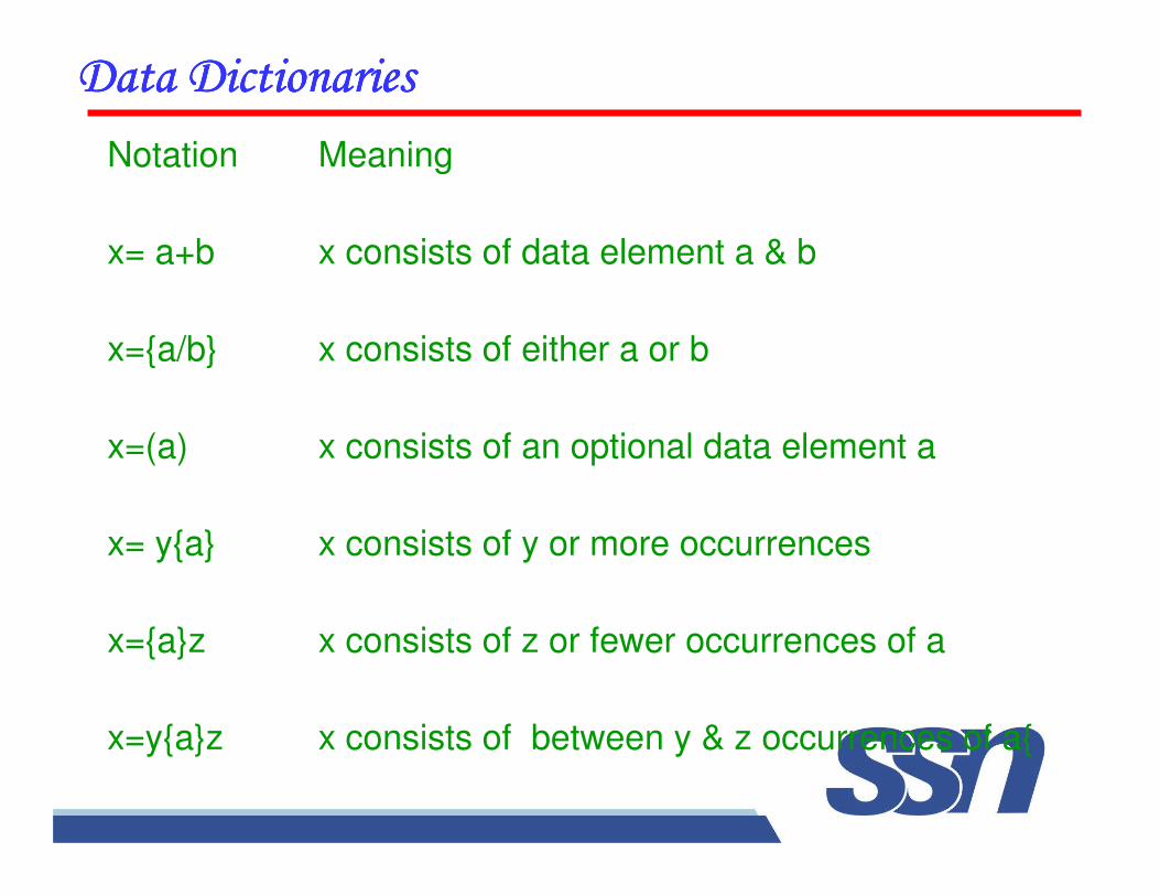
Notation Meaning
x= a+b x consists of data element a & b
x={a/b} x consists of either a or b
x=(a) x consists of an optional data element a
x= y{a} x consists of y or more occurrences
x={a}z x consists of z or fewer occurrences of a
x=y{a}z x consists of between y & z occurrences of a{
���������������� ��������!������������������!������������������!������������������!����������
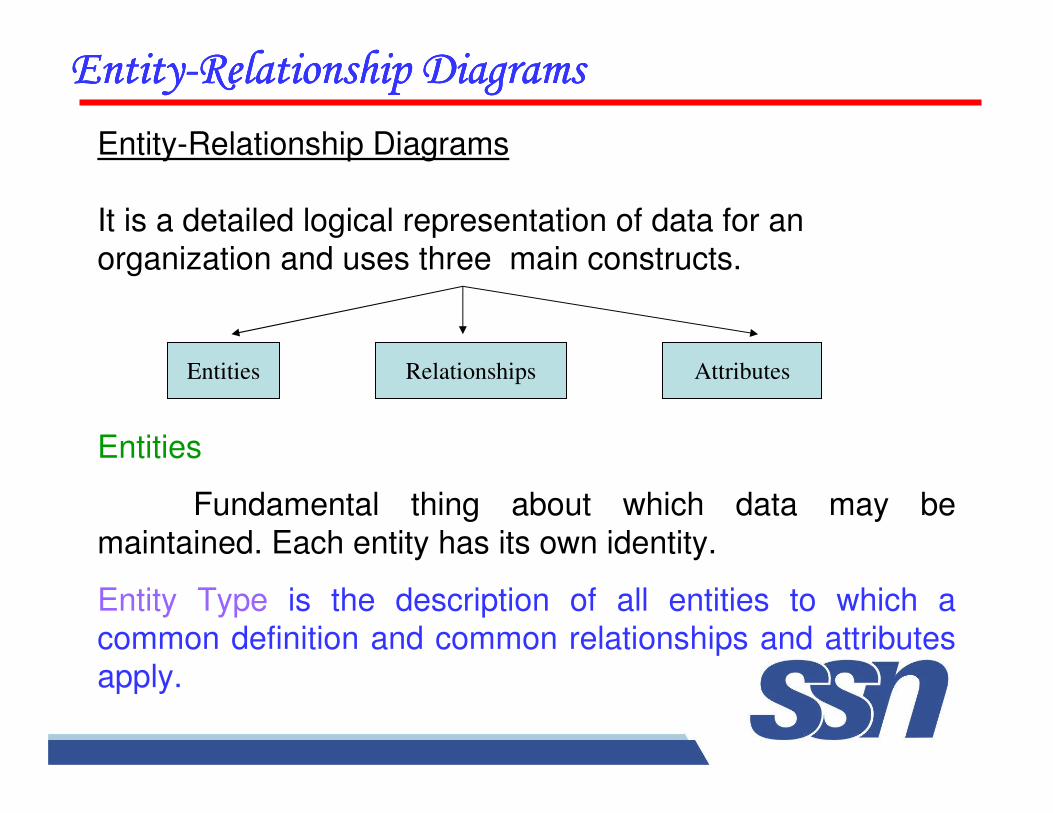
Entity-Relationship Diagrams
It is a detailed logical representation of data for an
organization and uses three main constructs.
Entities Relationships Attributes
Entities
Fundamental thing about which data may be
maintained. Each entity has its own identity.
Entity Type is the description of all entities to which a
common definition and common relationships and attributes apply.
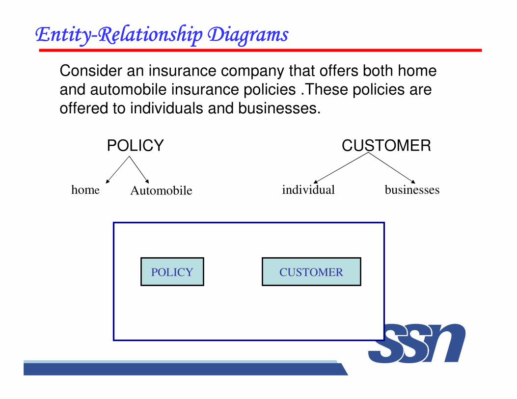
���������������� ��������!������������������!������������������!������������������!����������
Consider an insurance company that offers both home and automobile insurance policies .These policies are
offered to individuals and businesses.
POLICY CUSTOMER
home Automobile individual businesses
POLICY CUSTOMER
���������������� ��������!������������������!������������������!������������������!����������
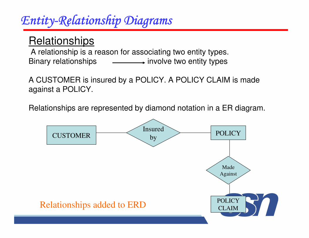
RelationshipsA relationship is a reason for associating two entity types.Binary relationships involve two entity types
A CUSTOMER is insured by a POLICY. A POLICY CLAIM is made against a POLICY.
Relationships are represented by diamond notation in a ER diagram.
CUSTOMERInsured
byPOLICY
POLICY
CLAIM
Made
Against
Relationships added to ERD
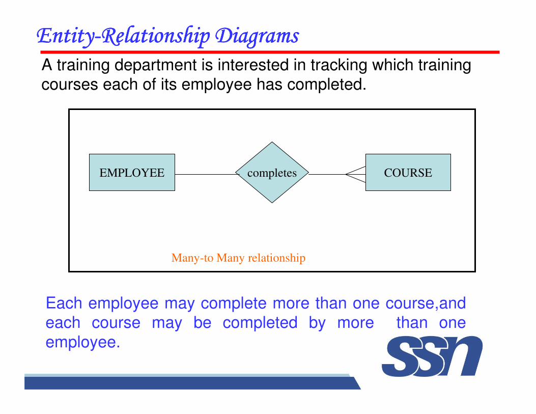
���������������� ��������!������������������!������������������!������������������!����������A training department is interested in tracking which training courses each of its employee has completed.
Each employee may complete more than one course,and each course may be completed by more than one
employee.
EMPLOYEE completes COURSE
Many-to Many relationship
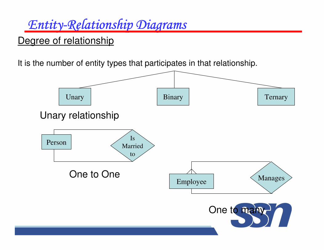
���������������� ��������!������������������!������������������!������������������!����������Degree of relationship
It is the number of entity types that participates in that relationship.
Unary Binary Ternary
Unary relationship
PersonIs
Married
to
EmployeeManagesOne to One
One to many
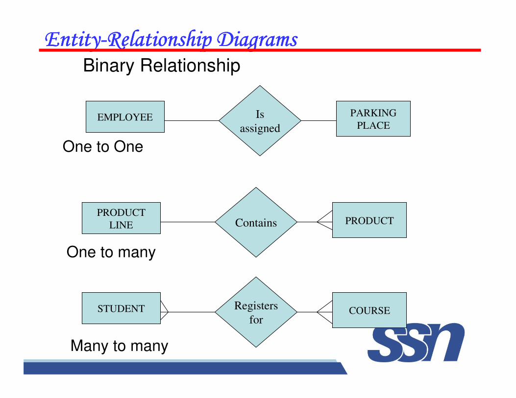
���������������� ��������!������������������!������������������!������������������!����������Binary Relationship
EMPLOYEE PARKING
PLACEIs
assigned
PRODUCT
LINE PRODUCTContains
STUDENT COURSERegisters
for
One to One
One to many
Many to many
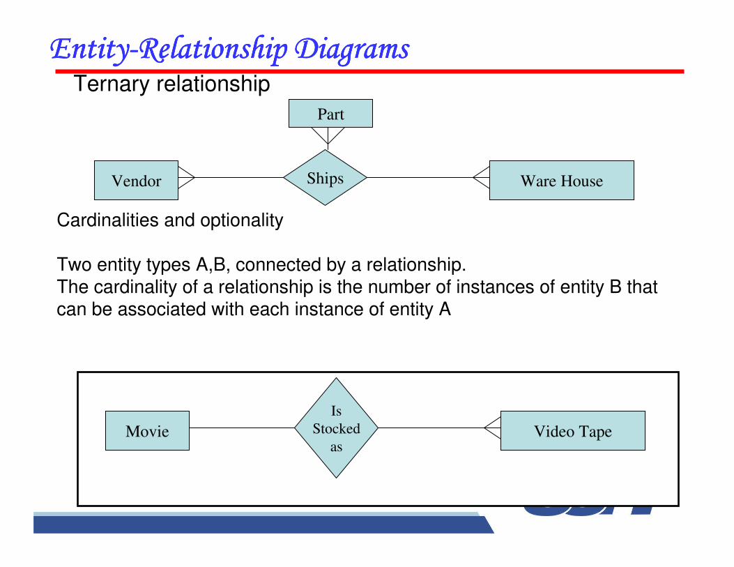
���������������� ��������!������������������!������������������!������������������!����������Ternary relationship
Part
Vendor Ware HouseShips
Cardinalities and optionality
Two entity types A,B, connected by a relationship.The cardinality of a relationship is the number of instances of entity B that can be associated with each instance of entity A
Movie Video Tape
Is
Stocked
as
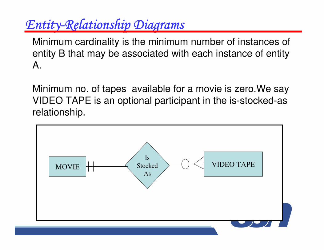
���������������� ��������!������������������!������������������!������������������!����������Minimum cardinality is the minimum number of instances of entity B that may be associated with each instance of entity
A.
Minimum no. of tapes available for a movie is zero.We say
VIDEO TAPE is an optional participant in the is-stocked-as relationship.
MOVIE VIDEO TAPEIs
Stocked
As
���������������� ��������!������������������!������������������!������������������!����������
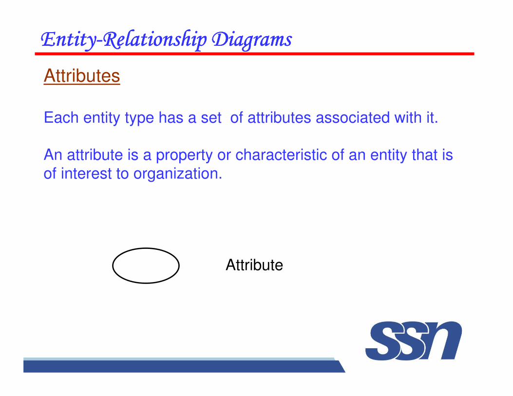
Attributes
Each entity type has a set of attributes associated with it.
An attribute is a property or characteristic of an entity that is
of interest to organization.
Attribute
���������������� ��������!������������������!������������������!������������������!����������
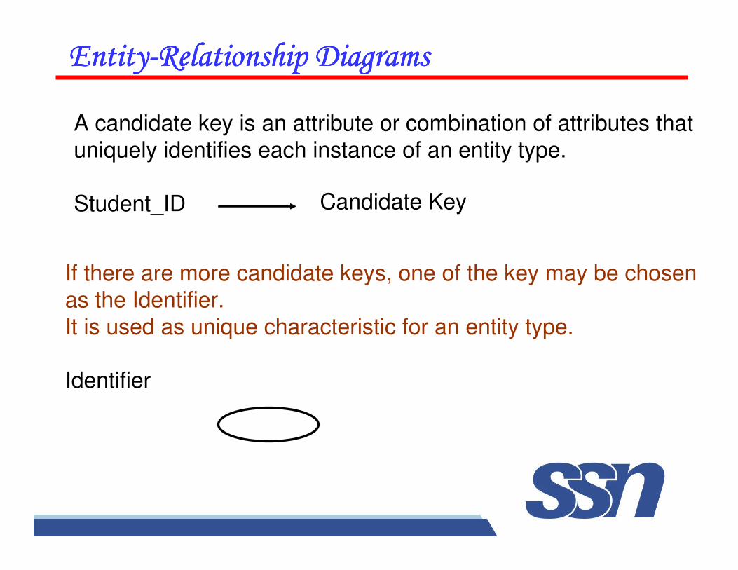
If there are more candidate keys, one of the key may be chosen
as the Identifier.
It is used as unique characteristic for an entity type.
Identifier
A candidate key is an attribute or combination of attributes that uniquely identifies each instance of an entity type.
Student_ID Candidate Key
���������������� ��������!������������������!������������������!������������������!����������
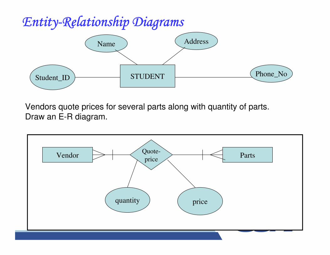
STUDENTStudent_ID
Name Address
Phone_No
Vendors quote prices for several parts along with quantity of parts.Draw an E-R diagram.
Quote-
priceVendor Parts
pricequantity
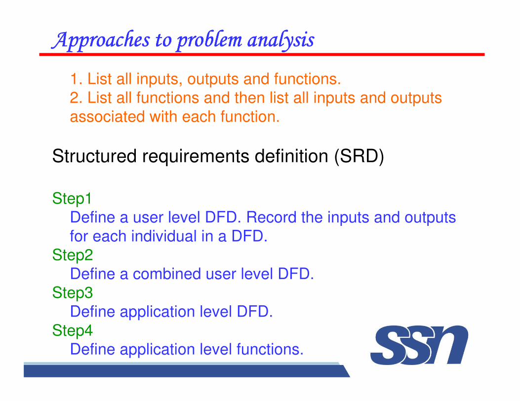
1. List all inputs, outputs and functions.2. List all functions and then list all inputs and outputs
associated with each function.
Structured requirements definition (SRD)
Step1Define a user level DFD. Record the inputs and outputs
for each individual in a DFD.Step2
Define a combined user level DFD. Step3
Define application level DFD.
Step4Define application level functions.
�������!�������������������������!�������������������������!�������������������������!������������������
����������������������������������������������������������������������������������������
This is the way of representing requirements in a consistent format
SRS serves many purpose depending upon who is writing it.
-- written by customer-- written by developer
Serves as contract between customer & developer.
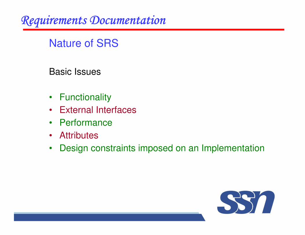
Nature of SRS
Basic Issues
• Functionality
• External Interfaces
• Performance
• Attributes
• Design constraints imposed on an Implementation
����������������������������������������������������������������������������������������
����������������������������������������������������������������������������������������
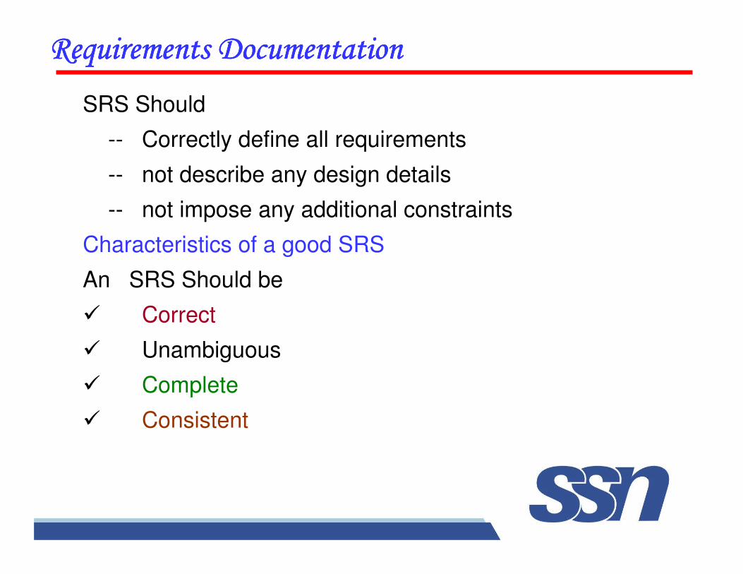
SRS Should
-- Correctly define all requirements
-- not describe any design details
-- not impose any additional constraints
Characteristics of a good SRS
An SRS Should be
� Correct
� Unambiguous
� Complete
� Consistent
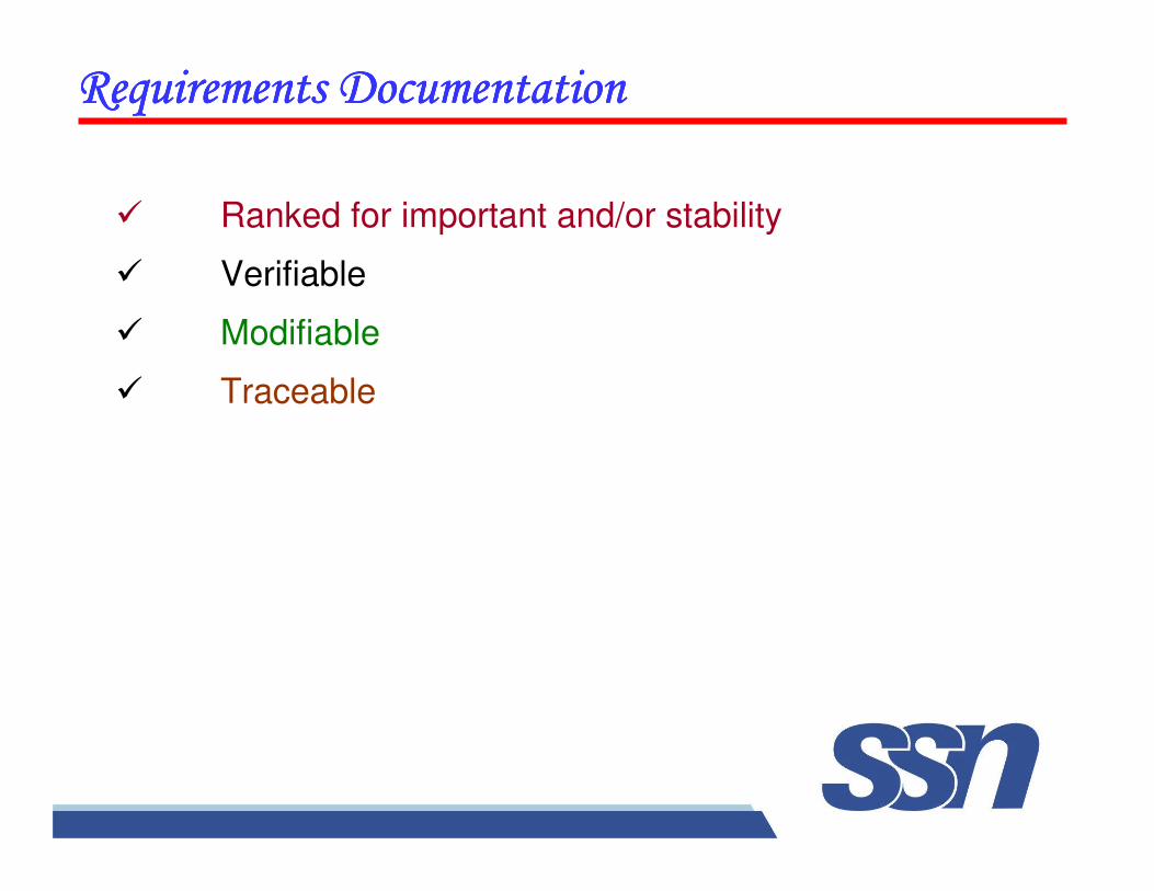
� Ranked for important and/or stability
� Verifiable
� Modifiable
� Traceable
����������������������������������������������������������������������������������������
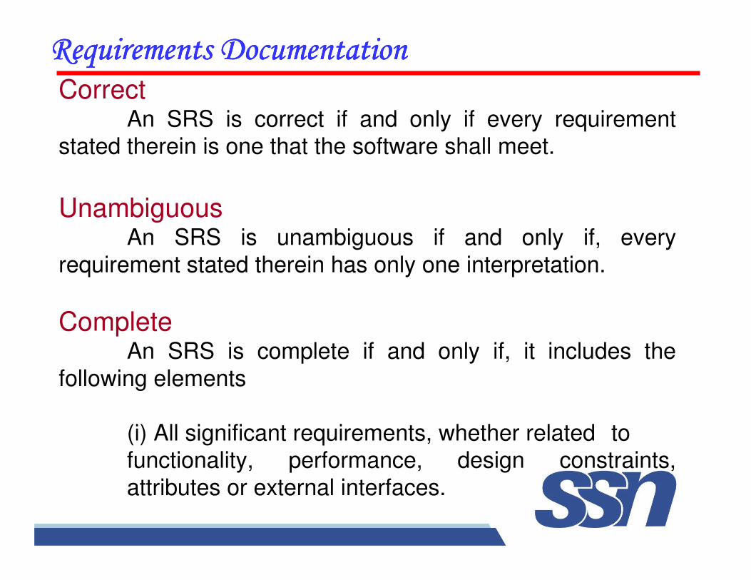
����������������������������������������������������������������������������������������Correct
An SRS is correct if and only if every requirement stated therein is one that the software shall meet.
UnambiguousAn SRS is unambiguous if and only if, every
requirement stated therein has only one interpretation.
CompleteAn SRS is complete if and only if, it includes the
following elements
(i) All significant requirements, whether related to functionality, performance, design constraints,
attributes or external interfaces.
����������������������������������������������������������������������������������������(ii) Responses to both valid & invalid inputs.
(iii) Full Label and references to all figures, tables and diagrams in the SRS and definition of all terms and units of measure.
Consistent
An SRS is consistent if and only if, no subset of individual requirements described in it conflict.
Ranked for importance and/or Stability
If an identifier is attached to every requirement to indicate either the importance or stability of that particular requirement.
����������������������������������������������������������������������������������������
VerifiableAn SRS is verifiable, if and only if, every requirement
stated therein is verifiable.
ModifiableAn SRS is modifiable, if and only if, its structure and style
are such that any changes to the requirements can be made easily, completely, and consistently while retaining structure and
style.
Traceable An SRS is traceable, if the origin of each of the
requirements is clear and if it facilitates the referencing of each requirement in future development or enhancement
documentation.
����������������������������������������������������������������������������������������
Organization of the SRS
IEEE has published guidelines and standards to organize an
SRS.First two sections are same. The specific tailoring occurs in
section-3.
1. Introduction
1.1 Purpose1.2 Scope
1.3 Definition, Acronyms and abbreviations1.4 References
1.5 Overview
����������������������������������������������������������������������������������������
2. The Overall Description
2.1 Product Perspective
2.1.1 System Interfaces
2.1.2 Interfaces
2.1.3 Hardware Interfaces
2.1.4 Software Interfaces
2.1.5 Communication Interfaces
2.1.6 Memory Constraints
2.1.7 Operations
2.1.8 Site Adaptation Requirements
����������������������������������������������������������������������������������������
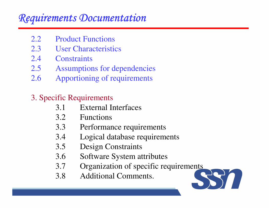
2.2 Product Functions
2.3 User Characteristics
2.4 Constraints
2.5 Assumptions for dependencies
2.6 Apportioning of requirements
3. Specific Requirements
3.1 External Interfaces
3.2 Functions
3.3 Performance requirements
3.4 Logical database requirements
3.5 Design Constraints
3.6 Software System attributes
3.7 Organization of specific requirements
3.8 Additional Comments.
�����������"�������������������"�������������������"�������������������"��������
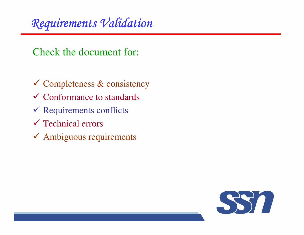
Check the document for:
� Completeness & consistency
� Conformance to standards
� Requirements conflicts
� Technical errors
� Ambiguous requirements
�����������"�������������������"�������������������"�������������������"��������
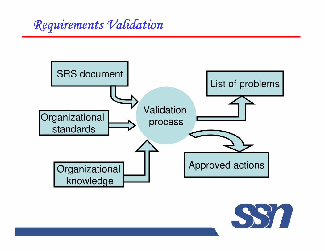
Validation
process
List of problems
Approved actions
SRS document
Organizational
standards
Organizational
knowledge
�������������#��$%�������������������#��$%�������������������#��$%�������������������#��$%������
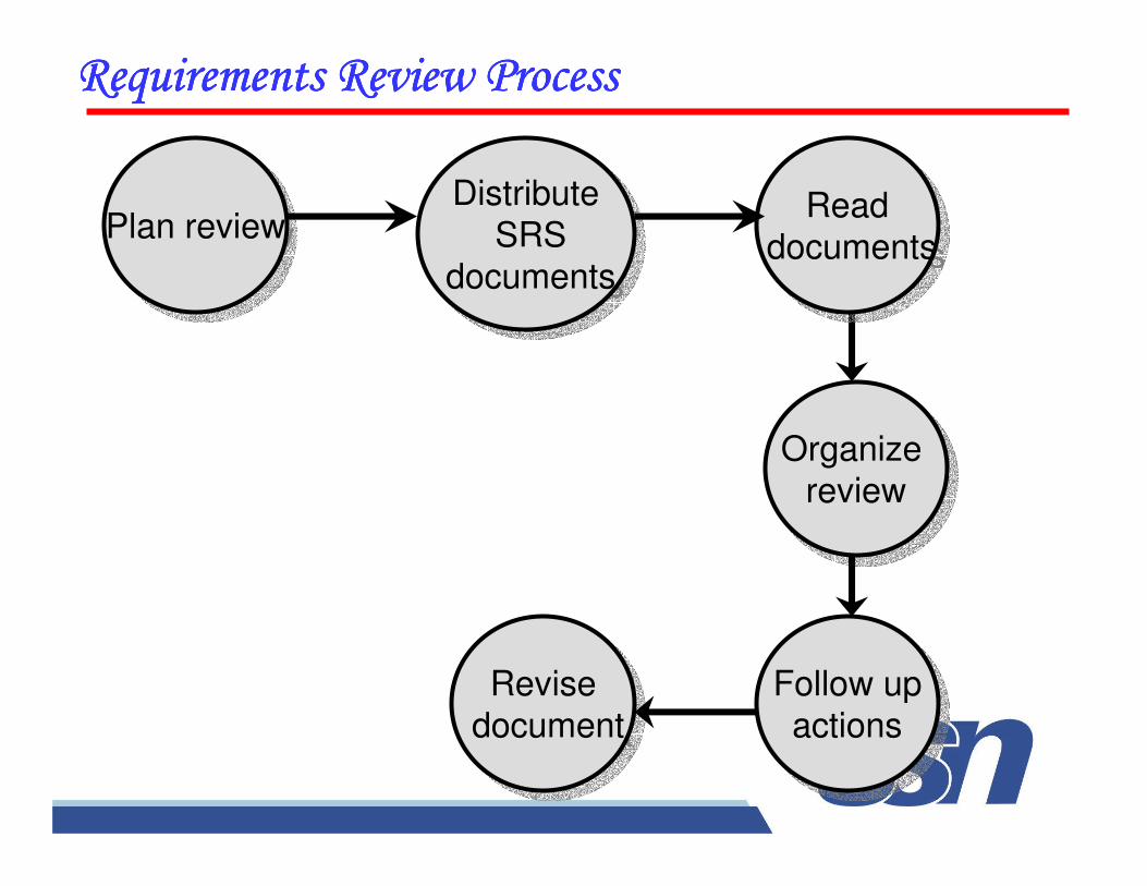
Plan reviewPlan reviewDistribute
SRSdocuments
Distribute
SRSdocuments
Readdocuments
Readdocuments
Organize
review
Organize
review
Revise
document
Revise
documentFollow up
actions
Follow up
actions
�����������"�������������������"�������������������"�������������������"��������
Problem actions
• Requirements clarification
• Missing information
• find this information from stakeholders
• Requirements conflicts
• Stakeholders must negotiate to resolve this conflict
• Unrealistic requirements
• Stakeholders must be consulted
• Security issues
• Review the system in accordance to security standards
� ��� ����'�
� �%�*(�������
� ��-!. !��
� �%��!����'�
� ��.��!/��!%�
� �%�$%����'�
� ���'��-!(!��
��#��$�!��&������#��$�!��&������#��$�!��&������#��$�!��&����
%��������%��������%��������%��������
0�(!���!%�� *�%�%��*�� �&% (�� -�� ����%��-(��'%�*(���� 1� �$$!'!���� 1� �&% (�� -�� ���� ��� �&����� !�����������
�����������'�������������������'�������������������'�������������������'��������
" ��%'����%$� ���������!�.�����'%���%((!�.�'&��.����%����������� !��������
�����2�1�0����������3����4��
% ��� �!�.� ��� !�������5� �&��� ���� '%������ !��������1�������(������%���!���'�!)!���%$��&��%�.��!/��!%��
�6��*(�5�!�� ����� ���%$���-%%78�'���(%.!�.���'�
% 0%(��!(�� ��� !�������5� (!7�(�� �%� '&��.�� � �!�.��%$�#������)�(%*�����(!$���'�'(��%���$������(!)����%$��&��*�%� '�
�����������'��������%������������������'��������%������������������'��������%������������������'��������%�������
" 0����'�!�!'�(�
" ��*%������$%���&��� ''����%$�����*�%9�'��
������������!����'��������������������!����'��������������������!����'��������������������!����'��������
" �((%'��!�.����� �������% �'��
" ���(��!��%$���� !�������
" �%' ����!�.���� !�������
" ��� !�����������'��-!(!��
" ����-(!�&!�.������'%�� �!'��!%�
" ����-(!�&�����%$�-���(!��
Q:\IRM\PRIVATE\INITIATIATI\QA\QAPLAN\SRSPLAN.DOC
��$�����������$�����������$�����������$���������
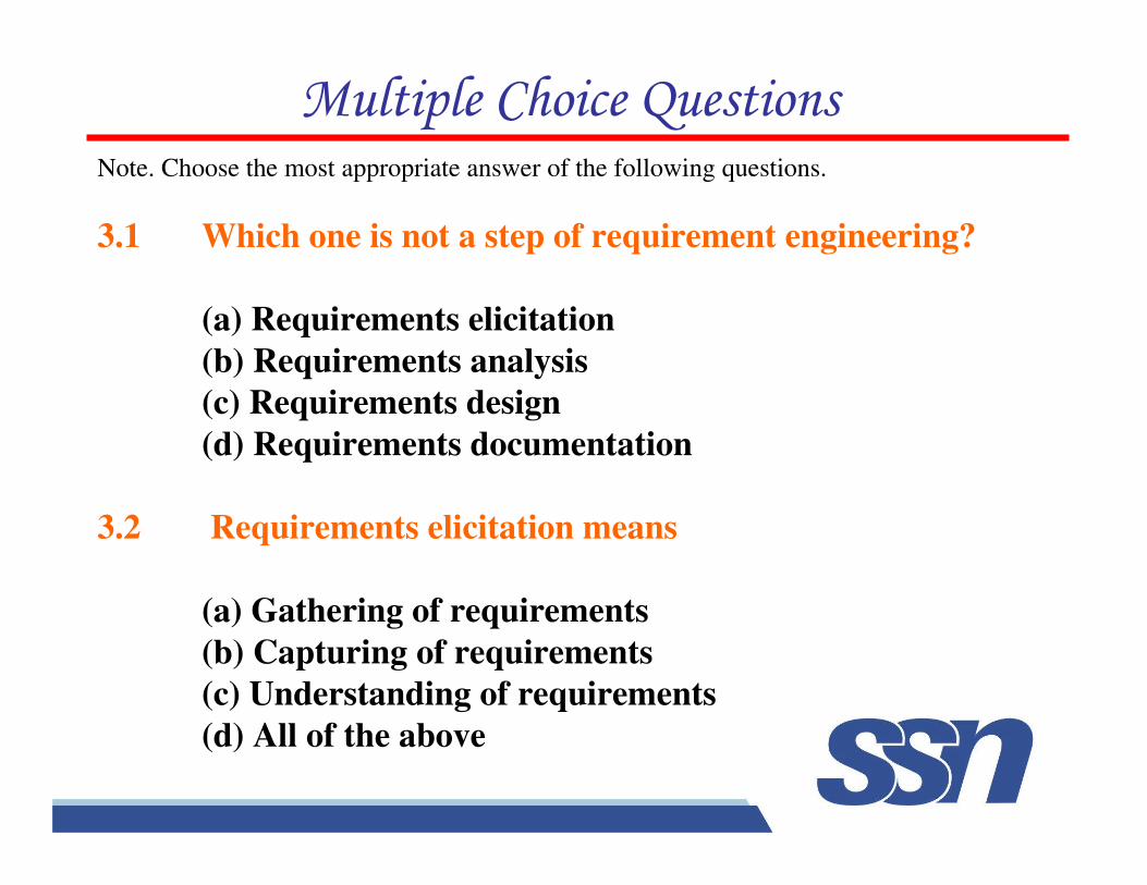
Note. Choose the most appropriate answer of the following questions.
3.1 Which one is not a step of requirement engineering?
(a) Requirements elicitation
(b) Requirements analysis
(c) Requirements design
(d) Requirements documentation
3.2 Requirements elicitation means
(a) Gathering of requirements
(b) Capturing of requirements
(c) Understanding of requirements
(d) All of the above
'�������!����(�������
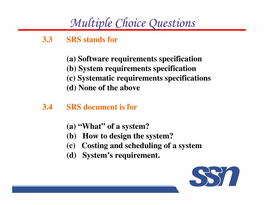
3.3 SRS stands for
(a) Software requirements specification
(b) System requirements specification
(c) Systematic requirements specifications
(d) None of the above
3.4 SRS document is for
(a) “What” of a system?
(b) How to design the system?
(c) Costing and scheduling of a system
(d) System’s requirement.
'�������!����(�������
3.5 Requirements review process is carried out to
(a) Spend time in requirements gathering
(b) Improve the quality of SRS
(c) Document the requirements
(d) None of the above
3.6 Which one of the statements is not correct during
requirements engineering?
(a) Requirements are difficult to uncover
(b) Requirements are subject to change
(c) Requirements should be consistent
(d) Requirements are always precisely known.
'�������!����(�������
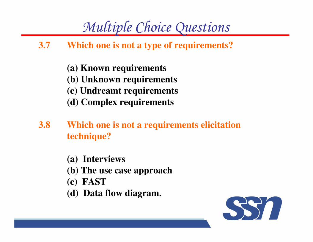
3.7 Which one is not a type of requirements?
(a) Known requirements
(b) Unknown requirements
(c) Undreamt requirements
(d) Complex requirements
3.8 Which one is not a requirements elicitation
technique?
(a) Interviews
(b) The use case approach
(c) FAST
(d) Data flow diagram.
'�������!����(�������
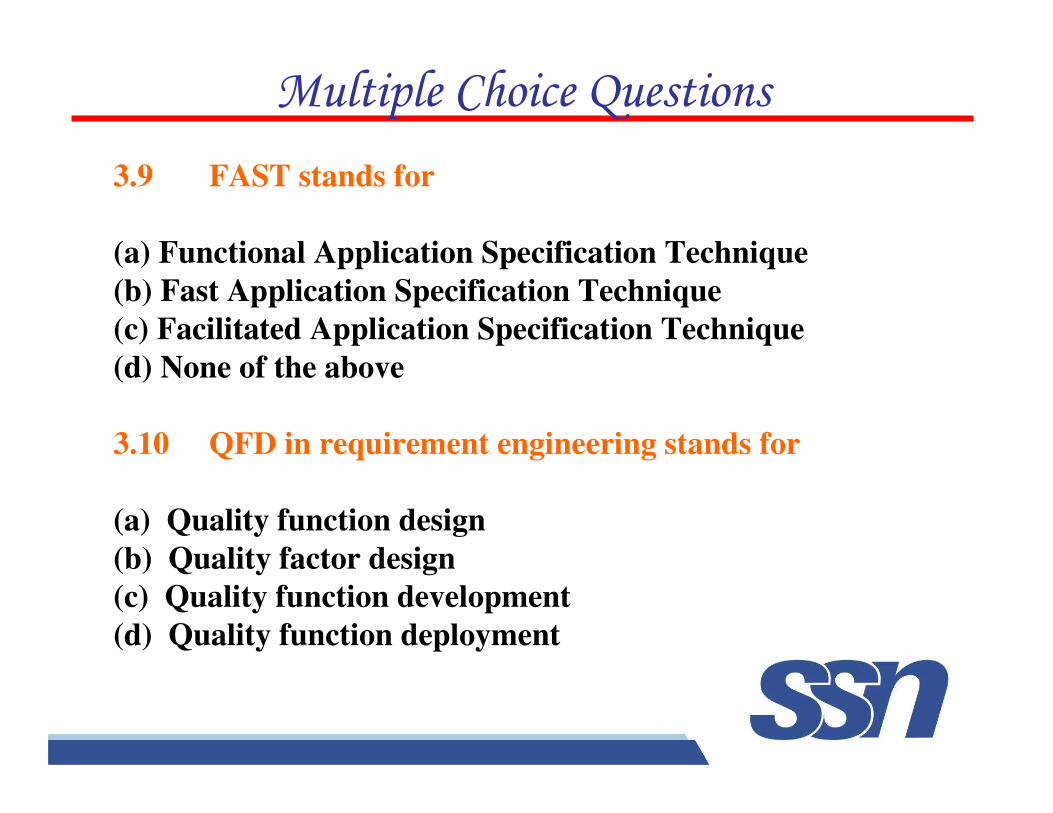
3.9 FAST stands for
(a) Functional Application Specification Technique
(b) Fast Application Specification Technique
(c) Facilitated Application Specification Technique
(d) None of the above
3.10 QFD in requirement engineering stands for
(a) Quality function design
(b) Quality factor design
(c) Quality function development
(d) Quality function deployment
'�������!����(�������
3.11 Which is not a type of requirements under
quality function deployment
(a) Normal requirements
(b) Abnormal requirements
(c) Expected requirements
(d) Exciting requirements
3.12 Use case approach was developed by
(a) I. Jacobson and others
(b) J.D. Musa and others
(c) B. Littlewood
(d) None of the above
'�������!����(�������
3.13 Context diagram explains
(a) The overview of the system
(b) The internal view of the system
(c) The entities of the system
(d) None of the above
3.14 DFD stands for
(a) Data Flow design
(b) Descriptive functional design
(c) Data flow diagram
(d) None of the above
'�������!����(�������
3.15 Level-O DFD is similar to
(a) Use case diagram
(b) Context diagram
(c) System diagram
(d) None of the above
3.16 ERD stands for
(a) Entity relationship diagram
(b) Exit related diagram
(c) Entity relationship design
(d) Exit related design
'�������!����(�������
3.17 Which is not a characteristic of a good SRS?
(a) Correct
(b) Complete
(c) Consistent
(d) Brief
3.18 Outcome of requirements specification phase is
(a) Design Document
(b) Software requirements specification
(c) Test Document
(d) None of the above
'�������!����(�������
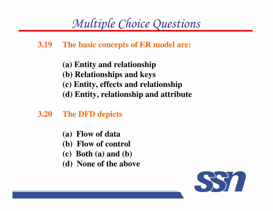
3.19 The basic concepts of ER model are:
(a) Entity and relationship
(b) Relationships and keys
(c) Entity, effects and relationship
(d) Entity, relationship and attribute
3.20 The DFD depicts
(a) Flow of data
(b) Flow of control
(c) Both (a) and (b)
(d) None of the above
'�������!����(�������
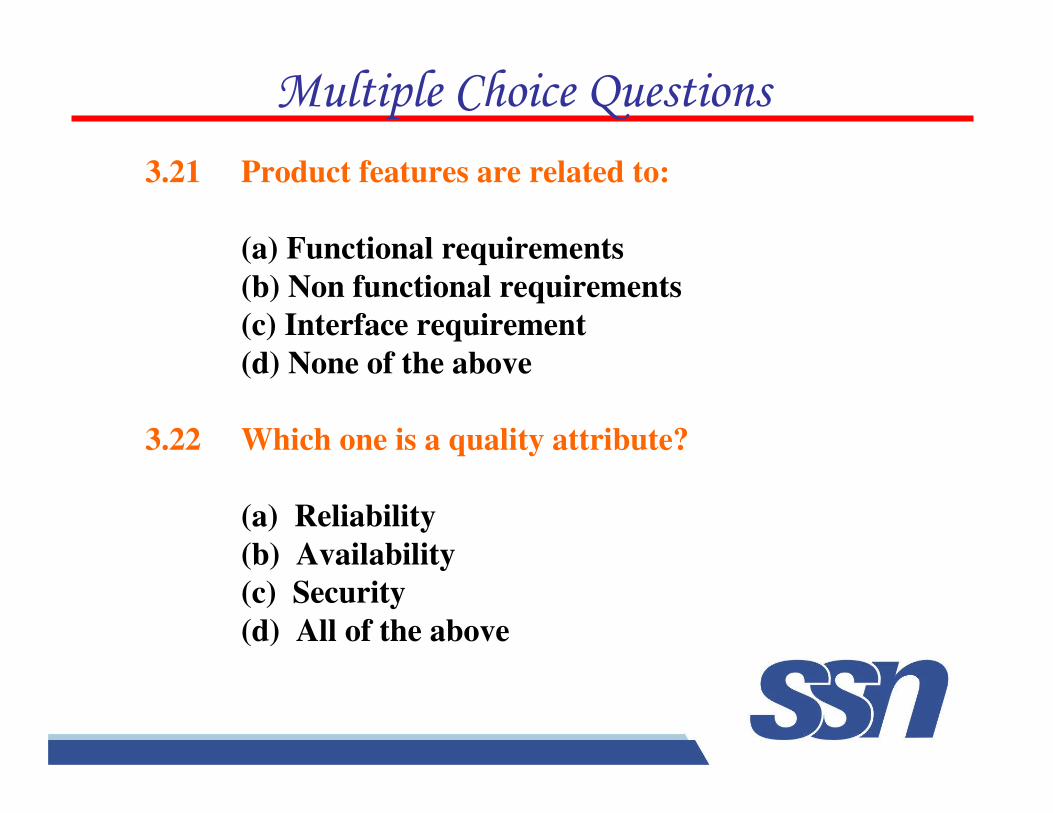
3.21 Product features are related to:
(a) Functional requirements
(b) Non functional requirements
(c) Interface requirement
(d) None of the above
3.22 Which one is a quality attribute?
(a) Reliability
(b) Availability
(c) Security
(d) All of the above
'�������!����(�������
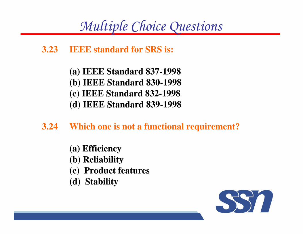
3.23 IEEE standard for SRS is:
(a) IEEE Standard 837-1998
(b) IEEE Standard 830-1998
(c) IEEE Standard 832-1998
(d) IEEE Standard 839-1998
3.24 Which one is not a functional requirement?
(a) Efficiency
(b) Reliability
(c) Product features
(d) Stability
'�������!����(�������
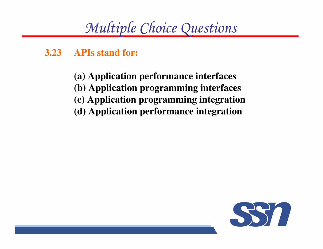
3.23 APIs stand for:
(a) Application performance interfaces
(b) Application programming interfaces
(c) Application programming integration
(d) Application performance integration
'�������!����(�������
�)�������
3.1 Discuss the significance and use of requirement engineering. What are the problems in the formulation of requirements?
3.2 Requirements analysis is unquestionably the most communication intensive step in the software engineering process. Why does thecommunication path frequently break down ?
3.3 What are crucial process steps of requirement engineering ? Discuss with the help of a diagram.
3.4 Discuss the present state of practices in requirement engineering. Suggest few steps to improve the present state of practice.
3.5 Explain the importance of requirements. How many types of requirements are possible and why ?
3.7 What do you understand with the term “requirements elicitation” ? Discuss any two techniques in detail.
3.8 List out requirements elicitation techniques. Which one is most popular and why ?
3.6 Describe the various steps of requirements engineering. Is it essential to follow these steps ?
�)�������
3.10 Discuss quality function deployment technique of requirements elicitation. Why an importance or value factor is associated with every requirement ?
3.11. Explain the use case approach of requirements elicitation. What are use-case guidelines ?
3.12. What are components of a use case diagram. Explain their usage with the help of an example.
3.13. Consider the problem of library management system and design thefollowing:
(i) Problem statement
(ii) Use case diagram
(iii) Use cases.
3.9 Describe facilitated application specification technique (FAST) and compare this with brainstorming sessions.
�)�������
3.14. Consider the problem of railway reservation system and design the following:
(i) Problem statement
(ii) Use case diagram
(iii) Use cases.
3.15. Explain why a many to many relationship is to be modeled as an associative entity ?
3.16. What are the linkages between data flow and E–R diagrams ?
3.17. What is the degree of a relationship ? Give an example of each of the relationship degree.
3.18. Explain the relationship between minimum cardinality and optional and mandatory participation.
3.19. An airline reservation is an association between a passenger, a flight, and a seat. Select a few
pertinent attributes for each of these entity types and represent a reservation in an E–R diagram.
�)�������
3.20. A department of computer science has usual resources and usual users for these resources. A software is to be developed so that resources are assigned without conflict. Draw a DFD specifying the above system.
3.21. Draw a DFD for result preparation automation system of B. Tech. courses (or MCA program) of any university. Clearly describe the working of the system. Also mention all assumptions made by you.
3.22. Write short notes on
(i) Data flow diagram
(ii) Data dictionary.
3.23. Draw a DFD for borrowing a book in a library which is explained below: “A borrower can borrow a book if it is available else he/she can reserve for the book if he/she so wishes. He/she can borrow a maximum of three books”.
3.24. Draw the E–R diagram for a hotel reception desk management.
Explain why, for large software systems development, is it recommended that prototypes should be “throw-away” prototype ?
�)�������
3.26. Discuss the significance of using prototyping for reusable components
and explain the problems,which may arise in this situation.
3.27. Suppose a user is satisfied with the performance of a prototype. If
he/she is interested to buy this
for actual work, what should be the response of a developer ?
3.28. Comment on the statement: “The term throw-away prototype is
inappropriate in that these prototypes expand and enhance the knowledge
base that is retained and incorporated in the final prototype; therefore they
are not disposed of or thrown away at all.”
3.29. Which of the following statements are ambiguous ? Explain why.
(a) The system shall exhibit good response time.
(b) The system shall be menu driven.
(c) There shall exist twenty-five buttons on the control panel, numbered PF1
to PF25.
(d) The software size shall not exceed 128K of RAM.
�)�������
3.30. Are there other characteristics of an SRS (besides listed in section
3.4.2) that are desirable ? List a few and describe why ?
3.31. What is software requirements specification (SRS) ? List out the
advantages of SRS standards.
Why is SRS known as the black box specification of a system ?
3.32. State the model of a data dictionary and its contents. What are its
advantages ?
3.33. List five desirable characteristics of a good SRS document. Discuss the
relative advantages of formal requirement specifications. List the important
issues, which an SRS must address.
3.34. Construct an example of an inconsistent (incomplete) SRS.
3.35. Discuss the organization of a SRS. List out some important issues of
this organization.
�)�������
3.36. Discuss the difference between the following:
(a) Functional & nonfunctional requirements
(b) User & system requirements
Top Related