


Languages
Pages
Legal

Report of Aerodrome Certification Simulation Exercise
KOLNDORF
EASA – Report of Aerodrome Certification Simulation Exercise – Kolndorf November 2011 Page 2 of 48
INTRODUCTION
The Aerodrome Rulemaking section has spent the last year developing the rules for oversight authorities, aerodrome operator organisations, aerodrome design and operations following the adoption of Regulation 1108/2009 that extended the responsibility of EASA to Aerodromes and ATM. This was achieved with the help of experts from the industry in the form of dedicated working groups.
To test the results of this work and to ensure the rules developed by group could be implemented, the aerodrome rulemaking section undertook a simulation exercise to create a Certification Basis (CB) for an existing yet fictitious certificated aerodrome. To ensure the exercise covered all the known alternative measures available to an NAA undertaking the exercise in the future, the rulemaking section developed its own model aerodrome, known as “Kolndorf” to use as a basis for the exercise.
It is important to note that the exercise stopped short of certificating the ‘operation’ of the aerodrome and merely looked at creating the CB. The mitigation measure developed to manage the hazards created by the existing deviations and non‐compliances would normally be included in the Aerodrome Manual and taken into account by the NAA while assessing the operation and management of the aerodrome.
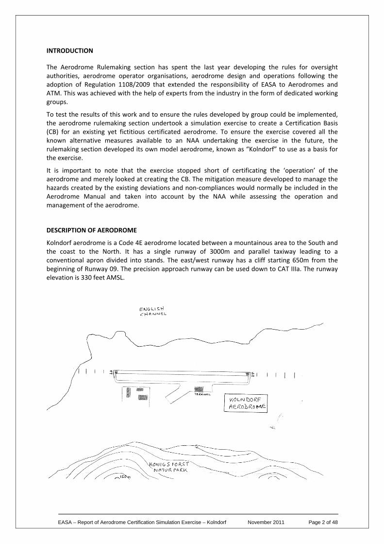
DESCRIPTION OF AERODROME
Kolndorf aerodrome is a Code 4E aerodrome located between a mountainous area to the South and the coast to the North. It has a single runway of 3000m and parallel taxiway leading to a conventional apron divided into stands. The east/west runway has a cliff starting 650m from the beginning of Runway 09. The precision approach runway can be used down to CAT IIIa. The runway elevation is 330 feet AMSL.
EASA – Report of Aerodrome Certification Simulation Exercise – Kolndorf November 2011 Page 3 of 48
The aerodrome has a number of deviations listed on its existing national Certificate, those being:
1. The RESA at the western end of the runway is 60m.
2. Distance between taxiway and runway centrelines is 160m.
3. Longitudinal slope on the parallel taxiway is 1.7%.
4. Industrial buildings infringe the taxiway strip by 3.5m.
5. The runway aiming point has different marking.
6. The apron taxiway has Orange and Blue centreline marking.
7. Approach lights for Runway 09 are truncated at a distance of 600m from Runway Threshold. For items 1, 2, 3, 5, 6 & 7 safety assessments were done which support the situation and that have been approved by the NAA.
CERTIFICATION EXERCISE
The exercise began with the aerodrome management requesting the NAA certificate the aerodrome under the new EASA rules. This request was initially denied because the aerodrome management had not included their proposed CB in the initial request.
Proposal was recent, with the accompanying CB proposal. The initial CB proposal form is included as Attachment A to this report. This form was used during the first meeting between the aerodrome and the NAA. It soon became clear that the initial form was too detailed and would prove difficult to complete if the aerodrome was more complex than the one we had designed for the exercise, therefore, following our first day’s attempt at certifying the aerodrome, it was decided a new form was needed.
The second day dawned with a new CB form, included as Attachment B to this report. The new form reduced the amount of detail and introduced the single column concept for the status of the aerodrome’s physical characteristics. This allowed the applicant to merely state whether the infrastructure met the Certification Specifications (CS) or not, and if not, the answer could be included in the comments column.
The improved form could also be used for multiple runways and allowed the applicant to supply additional pages for each runway if required.
Note: The CB forms included in Attachments A & B are examples developed by EASA for the simulation exercise. NAAs are free to develop a different form that they feel better suits their needs.
Now that the form had been modified to everyone’s liking, the certification process began in earnest. A number of times during the discussions, we had to remind ourselves that we were considering an existing certificated aerodrome and one that would be known to the NAA and had probably been subject to a number of oversight audits. Therefore, the need to ‘prove’ compliance would be significantly reduced when compared to certificating an unknown aerodrome, i.e. a new aerodrome.
The expected ‘couple of days’ to run through the certification process actually took eight days. Most of the time was spent deciding which deviations qualified as an Equivalent Level of Safety (ELOS), a Special Condition (SC) or the Deviation Acceptance and Action Document (DAAD). This process was necessary as the term ‘deviation’ or ‘variation’ does not exist in the new certification process. All deviations have to be allocated as either an ELOS, SC or DAAD.
EASA – Report of Aerodrome Certification Simulation Exercise – Kolndorf November 2011 Page 4 of 48
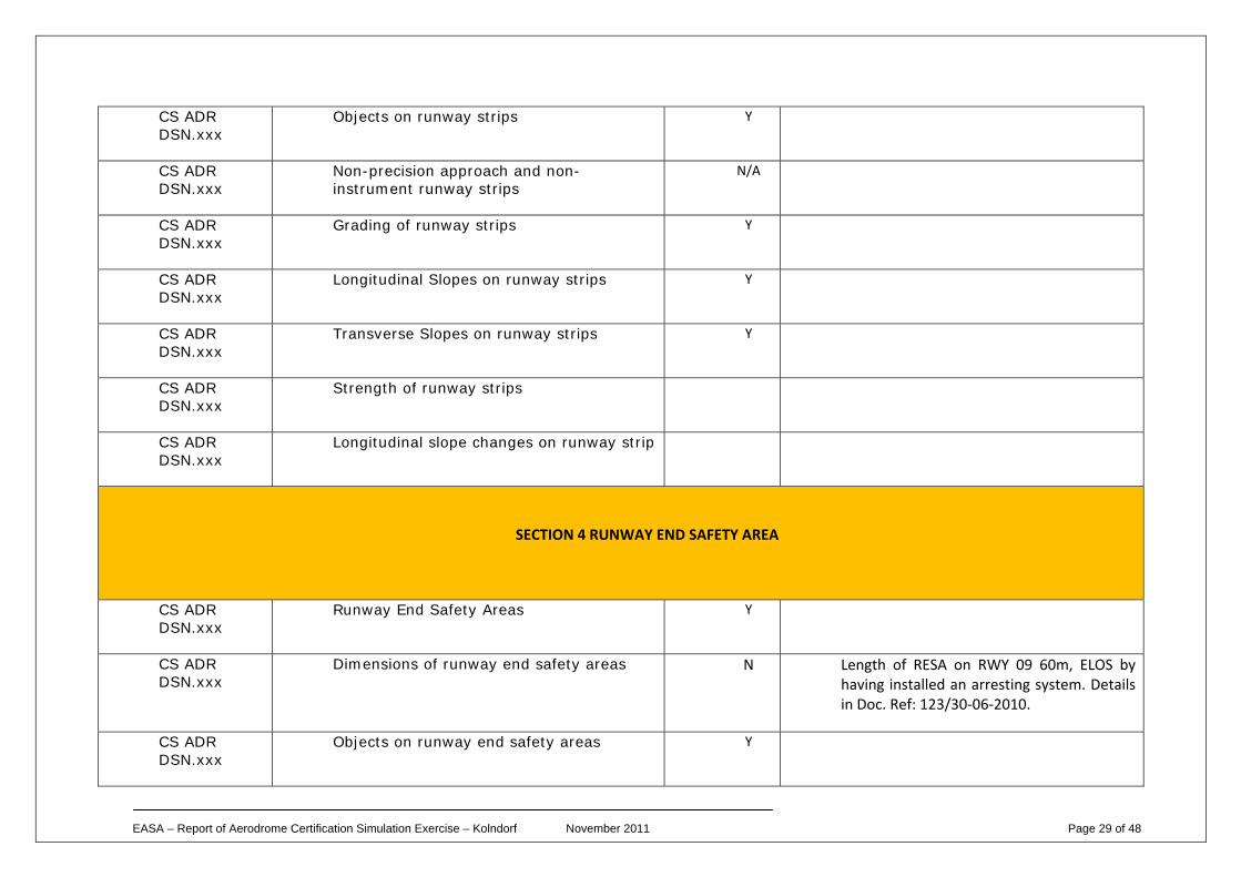
Reviewing each deviation in turn, we began with the RESA. The CS states that the minimum RESA should be 90m, but should aim to achieve 240m. The RESA at the 09 end of the runway could only achieve a distance of 60m. This, when added to the 60m of runway strip, gave a total safety distance of 120m from the end of the runway. Following a safety assessment of the situation, the aerodrome had elected to install an EMAS arresting system beginning at the end of the runway and extending the full 120m, designed to FAA specification. The NAA accepted that the aerodrome operator had done all that was possible to maintain a safe runway environment and therefore agreed that the appropriate tools to address this situation was an ELOS.
Note: This tool was chosen by the team because the aerodrome had demonstrated an Equivalent Level of Safety to the provision of standard RESA, as described in the CS, by providing the EMAS.
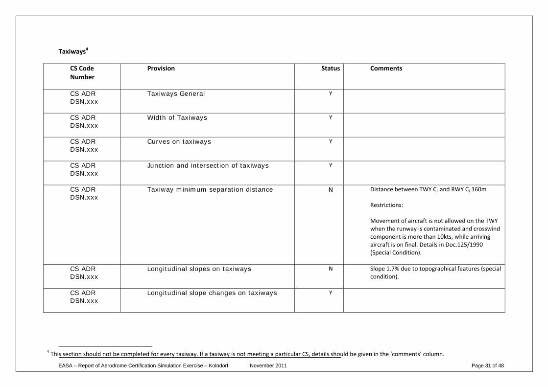
The next item on the deviation list was the taxiway separation distance from the runway. According to the CS this should be 180m; however, the aerodrome could only achieve 160m without considerable construction work and expense. To move the taxiway to the correct separation distance would be impossible due to the proximity of the surrounding environment. Therefore, the only option would be to move the runway closer to the sea. There was an existing condition on the operation of the taxiway that stated movement of aircraft is not allowed on the taxiway when the runway is contaminated and crosswind component is more than 10kts, while arriving aircraft are on finals to land. The team argued that this ‘condition’ could be extended to include operation in low visibility. This was agreed by the aerodrome operator and would be included in the Aerodrome Manual. Therefore, the NAA agreed to place a Special Condition on the Certificate stating the extended conditions agreed by the aerodrome operator.
Note: The SC was chosen as the appropriate tool in this case because it met the condition of the CS. Described in the Basic Regulation when the certification specifications established by the EASA are not adequate or are inappropriate to ensure conformity of the aerodrome with the essential requirements of Annex Va to the Regulation (EC) No 216/2008. The CS in this case was deemed inappropriate because to meet it would incur substantial cost and disruption to the aerodrome operator. Following a safety assessment, the aerodrome, along with the NAA, has agreed a set of conditions that demonstrate the safe use of the taxiway in all weather conditions, therefore an SC was seen as the appropriate tool.
The next deviation was the longitudinal slope on the taxiway. The CS states this should not be above 1.5%, whereas in this case it was 1.7%. The aerodrome operator had a safety assessment that proposed mitigation measures that included additional inspections of the taxiway during icing conditions and application of de‐icer when those conditions warranted it. The aerodrome operator had also installed signage to indicate the beginning and end of the slope and included an entry in the AIP warning pilots of the hazard and the need to manage both braking and power settings. The taxiway would be closed when sufficient friction could not be achieved in severe icing conditions. Similar to the above example, to achieve the correct longitudinal slope would incur substantial costs and disruption. The project would involve re‐grading most of the ground surrounding the length of taxiway and would probably impact on the runway profile. Therefore, the team agreed a SC was the appropriate tool in this case.
Note: The SC was chosen because the aerodrome operator was affected by the natural ground of the aerodrome and to meet the CS would involve ‘chasing’ the levels for most of the aerodrome before meeting the CS. Not a sensible option for the benefit of 0.2%. Additionally, the aerodrome operator has developed mitigation measures that ensured the safe operational use of the taxiway.
In addition to the circumstances described above, both options resulted in an SC because of the long term nature of the situation, whereas with the other tools available, there is the possibility to review following any developments on the aerodrome.
EASA – Report of Aerodrome Certification Simulation Exercise – Kolndorf November 2011 Page 5 of 48
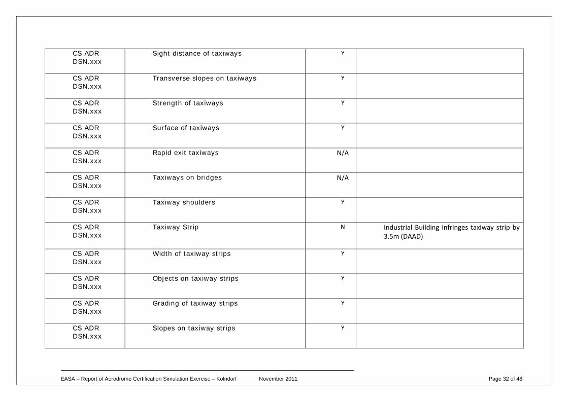
The next deviation was the industrial building affecting the taxiway strip. The taxiway had been designed at a time when Code E dimensions only included wingspan of up to, but not including 60m (Boeing 747 classic), then, following the introduction of the B747‐400, increased to 65m. The aerodrome became the victim of this change to the Aerodrome Reference Code and has little opportunity to meet the required CS without demolishing the industrial buildings. The introduction of the new rules has resulted in the aerodrome operator undertaking a safety assessment of the hazard and concluding that nothing has to be done to ensure safety of the aircraft passing the restriction. Therefore, is proposed that this item be transferred to the DAAD with the action that any future development that affects the area will take into account the removal of the deviation.
Note: The decision to place this item on the DAAD resulted from the fact that little could be done at this time to achieve the CS, again without substantial cost and disruption. However, the safety assessment had indicated that the restriction on the taxiway strip did not adversely affect the safety of the aircraft and it is possible that the aerodrome will be able to demolish the industrial buildings in the future and move the taxiway to the correct location. This had been indicated in the aerodrome strategic plan for the introduction of the A380 to the aerodrome. Therefore, the DAAD seemed the best tool to use to both monitor the development opportunities and ease of removal of the deviation.
The next deviation involved the use of a different runway aiming point marking to that indicated in the CS. The aerodrome had for many years used the aiming point marking described in the national regulation. The NAA had filed a difference with ICAO that had been accepted and had demonstrated that the national aiming point provided a better visual reference than the ICAO one. The team agreed that this qualified as an ELOS because the NAA had provided a safety assessment that demonstrated the alternative aiming point met the intent of the CS.
Note: The ELOS was chosen in this case because a safety assessment demonstrated an equivalent level of safety. However, we did debate the situation whereby the aerodrome has complied with national regulation prior to the new rules and whether an NAA could provide a ‘National’ ELOS. The answer is included in Attachment C to this report.
The next deviation involved the use of different coloured taxiway centrelines to those described in the CS. The aerodrome operator had installed different coloured centreline marking on the apron taxilane. This was done with advice provided in the ACI World aerodrome operation manual to identify taxiway centrelines that could be used by different sized aircraft. The aerodrome operator had undertaken a safety assessment and provided the information in the AIP. The NAA had agreed to the use of the centrelines following the lodging of the safety assessment with the NAA. The team assessed the ELOS as the best tool to use in this situation.
Note: Much debate centred on this subject as it was felt by some that the CS could easily be met and that differences like this should be included in the deviation. However, it was finally agreed that as long as the aerodrome operator could prove an equivalent level of safety through a safety assessment, they should be allowed to install the facility.
The final deviation involved the truncation of the approach lights at 600m instead of the 900m as indicated in the CS for a precision approach runway for CAT IIIa. This was due to the proximity of the cliff face. The sheer drop of 300+ft resulted in the inappropriateness of installing the remaining approach lights. The aerodrome operator had undertaken a safety assessment that indicated a revision of the DA/DH was needed to ensure the safety of aircraft on the approach to Runway 09. In good visibility, there were enough lights to enable an easy transition from instrument to visual flight and in low visibility, the need for extra lights when undertaking an instrument approach is not necessary. Therefore, the team were satisfied that an equivalent level of safety had been demonstrated.
EASA – Report of Aerodrome Certification Simulation Exercise – Kolndorf November 2011 Page 6 of 48
Note: This was an easy one to agree as an ELOS because of the (slightly convoluted) opinion that additional lights are needed in reduced visibility when, by nature, you cannot see them anyway, and because the aerodrome had modified the DA/DH.
This concluded the certification process with regard to ‘building’ the CB. Once this stage is complete, the normal process would be to review the operation of the aerodrome as described in the Aerodrome Manual. However, the team did see the construction of the CB and the reviewing of the operation as a single entity leading to the awarding of the Certificate.
The process did lead to some questions process and these have been included in Attachment C to this report.
Disclaimer
It is important to understand that the EASA Aerodrome Rulemaking Section staged the simulation to test the structure of the rules, acting out the part of both the aerodrome operator, as applicant for certification under the EASA rules, and the NAA. The decision to publish this report was taken to help those NAA and aerodrome operators that fall within the scope (see ‘3a’ of Regulation 1108/2009) understand the thought processes involved in certificating an aerodrome using the new rules. The mitigation measures developed during the exercise represent examples of the many ways to solving the issues. It should not be taken by the reader that EASA has endorsed the solutions described herein, or that they will take part in the decision‐making interaction between the applicant and the NAA. The decision on which tool is suitable to use for their aerodrome’s existing deviations, rests with the NAA.
END
EASA – Report of Aerodrome Certification Simulation Exercise – Kolndorf November 2011 Page 7 of 48
EASA CERTIFICATION BASIS Attachment A
KOLNDORF AERODROME
Precision Approach Runway Cat IIIa
Parallel TWY A leading from apron to the runway
Aerodrome reference code 4E
The aerodrome is bounded by:
1. Sea, north of the RWY at a distance of 450m from RWY CL 2. Hill, 150m high, south of the RWY at a distance of 4 km from RWY CL 3. Cliff, starting 650m from the beginning of RWY 09
RUNWAYS
09 27 TWY A Comments
CS ADR DSN.xxx
Number, siting and orientation of runways
CS ADR DSN.xxx
Choice of maximum permissible crosswind components
CS ADR DSN.xxx
Data to be used
CS ADR DSN.xxx
Runway threshold Y Y
EASA – Report of Aerodrome Certification Simulation Exercise – Kolndorf November 2011 Page 8 of 48
CS ADR DSN.xxx
Actual length of the runway (m)
3000 3000
CS ADR DSN.xxx
Runways with stopways or clearways
N/A N/A
CS ADR DSN.xxx
Width of runways 45m 45m
CS ADR DSN.xxx
Minimum distance between parallel non-instrument runways
N/A N/A
CS ADR DSN.xxx
Minimum distance between parallel instrument runways
N/A N/A
CS ADR DSN.xxx
Longitudinal slopes of runways 1% 1%
CS ADR DSN.xxx
Longitudinal runway slope changes
N N
CS ADR DSN.xxx
Sight distance Y Y
CS ADR DSN.xxx
Distance between slope changes
300m 300m
CS ADR DSN.xxx
Transverse slopes 1.5% 1.5%
CS ADR DSN.xxx
Runway strength Y Y 78/F/B/W/T
CS ADR DSN.xxx
Surface of runways Asphalt
EASA – Report of Aerodrome Certification Simulation Exercise – Kolndorf November 2011 Page 9 of 48
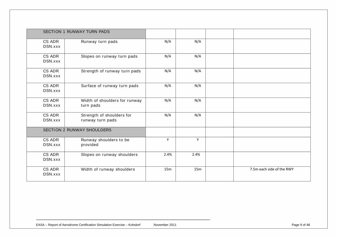
SECTION 1 RUNWAY TURN PADS
CS ADR DSN.xxx
Runway turn pads N/A N/A
CS ADR DSN.xxx
Slopes on runway turn pads N/A N/A
CS ADR DSN.xxx
Strength of runway turn pads N/A N/A
CS ADR DSN.xxx
Surface of runway turn pads N/A N/A
CS ADR DSN.xxx
Width of shoulders for runway turn pads
N/A N/A
CS ADR DSN.xxx
Strength of shoulders for runway turn pads
N/A N/A
SECTION 2 RUNWAY SHOULDERS
CS ADR DSN.xxx
Runway shoulders to be provided
Y Y
CS ADR DSN.xxx
Slopes on runway shoulders 2.4% 2.4%
CS ADR DSN.xxx
Width of runway shoulders 15m 15m 7.5m each side of the RWY
EASA – Report of Aerodrome Certification Simulation Exercise – Kolndorf November 2011 Page 10 of 48
CS ADR DSN.xxx
Strength of runway shoulders
CS ADR DSN.xxx
Surface of runway shoulders Y Y Asphalt
SECTION 3 RUNWAY STRIP
CS ADR DSN.xxx
Runway strip to be provided Y Y
CS ADR DSN.xxx
Length of runway strip 3120m 3120m
CS ADR DSN.xxx
Width of runway strip 300m 300m
CS ADR DSN.xxx
Objects on runway strips Y Y ILS Glidepath antenna, transmissometers
CS ADR DSN.xxx
Non-precision approach and non-instrument runway strips
N/A N/A
CS ADR DSN.xxx
Grading of runway strips 75m 75m
CS ADR DSN.xxx
Longitudinal Slopes on runway strips
1.5% 1.5%
CS ADR DSN.xxx
Transverse Slopes on runway strips
2.5% 2.5%
CS ADR DSN.xxx
Strength of runway strips
CS ADR DSN.xxx
Longitudinal slope changes on runway strip
EASA – Report of Aerodrome Certification Simulation Exercise – Kolndorf November 2011 Page 11 of 48
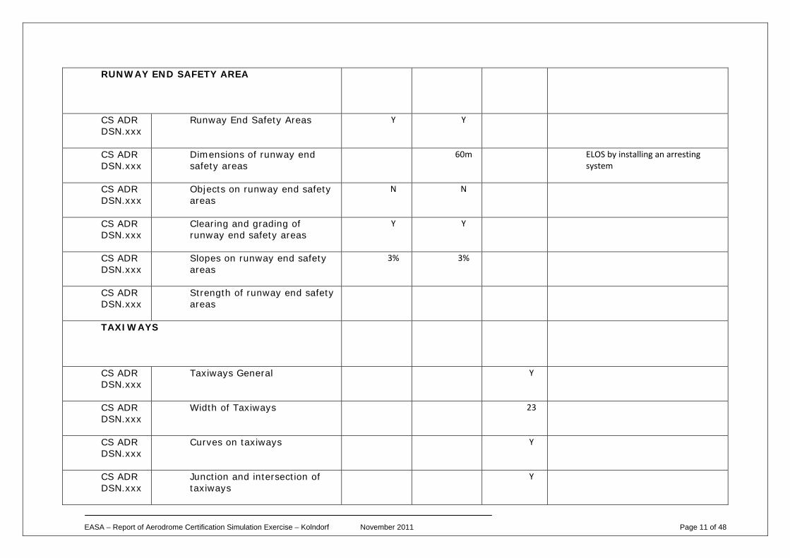
RUNWAY END SAFETY AREA
CS ADR DSN.xxx
Runway End Safety Areas Y Y
CS ADR DSN.xxx
Dimensions of runway end safety areas
60m ELOS by installing an arresting system
CS ADR DSN.xxx
Objects on runway end safety areas
N N
CS ADR DSN.xxx
Clearing and grading of runway end safety areas
Y Y
CS ADR DSN.xxx
Slopes on runway end safety areas
3% 3%
CS ADR DSN.xxx
Strength of runway end safety areas
TAXIWAYS
CS ADR DSN.xxx
Taxiways General Y
CS ADR DSN.xxx
Width of Taxiways 23
CS ADR DSN.xxx
Curves on taxiways Y
CS ADR DSN.xxx
Junction and intersection of taxiways
Y
EASA – Report of Aerodrome Certification Simulation Exercise – Kolndorf November 2011 Page 12 of 48
CS ADR DSN.xxx
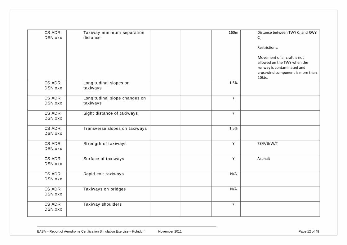
Taxiway minimum separation distance
160m Distance between TWY CL and RWY CL
Restrictions:
Movement of aircraft is not allowed on the TWY when the runway is contaminated and crosswind component is more than 10kts.
CS ADR DSN.xxx
Longitudinal slopes on taxiways
1.5%
CS ADR DSN.xxx
Longitudinal slope changes on taxiways
Y
CS ADR DSN.xxx
Sight distance of taxiways Y
CS ADR DSN.xxx
Transverse slopes on taxiways 1.5%
CS ADR DSN.xxx
Strength of taxiways Y 78/F/B/W/T
CS ADR DSN.xxx
Surface of taxiways Y Asphalt
CS ADR DSN.xxx
Rapid exit taxiways N/A
CS ADR DSN.xxx
Taxiways on bridges N/A
CS ADR DSN.xxx
Taxiway shoulders Y
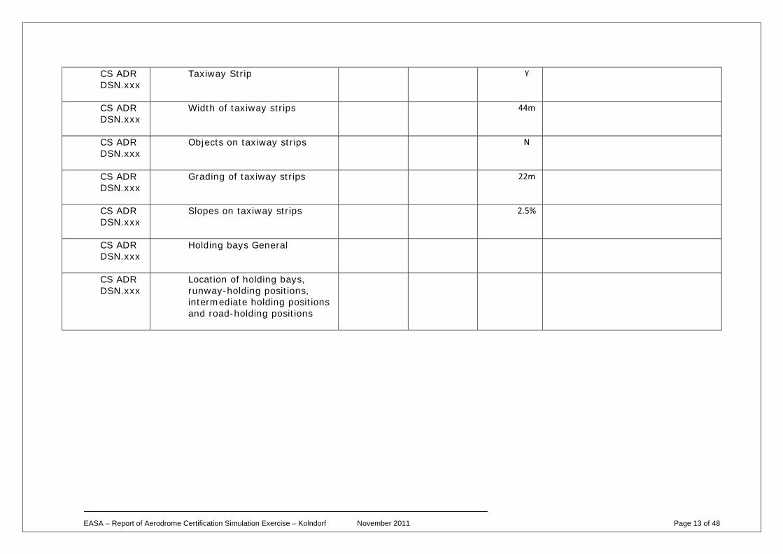
EASA – Report of Aerodrome Certification Simulation Exercise – Kolndorf November 2011 Page 13 of 48
CS ADR DSN.xxx
Taxiway Strip Y
CS ADR DSN.xxx
Width of taxiway strips 44m
CS ADR DSN.xxx
Objects on taxiway strips N
CS ADR DSN.xxx
Grading of taxiway strips 22m
CS ADR DSN.xxx
Slopes on taxiway strips 2.5%
CS ADR DSN.xxx
Holding bays General
CS ADR DSN.xxx
Location of holding bays, runway-holding positions, intermediate holding positions and road-holding positions
EASA – Report of Aerodrome Certification Simulation Exercise – Kolndorf November 2011 Page 14 of 48
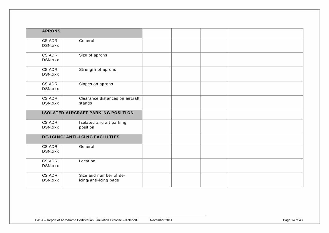
APRONS
CS ADR DSN.xxx
General
CS ADR DSN.xxx
Size of aprons
CS ADR DSN.xxx
Strength of aprons
CS ADR DSN.xxx
Slopes on aprons
CS ADR DSN.xxx
Clearance distances on aircraft stands
ISOLATED AIRCRAFT PARKING POSITION
CS ADR DSN.xxx
Isolated aircraft parking position
DE-ICING/ANTI-ICING FACILITIES
CS ADR DSN.xxx
General
CS ADR DSN.xxx
Location
CS ADR DSN.xxx
Size and number of de-icing/anti-icing pads
EASA – Report of Aerodrome Certification Simulation Exercise – Kolndorf November 2011 Page 15 of 48
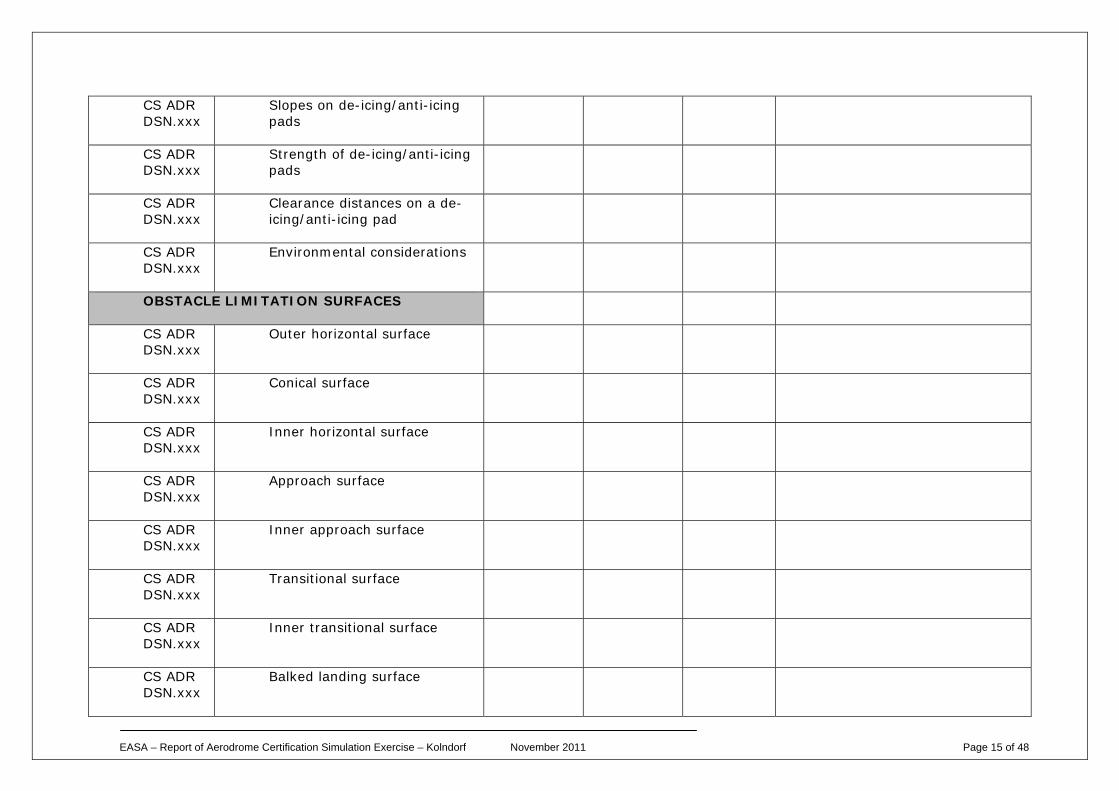
CS ADR DSN.xxx
Slopes on de-icing/anti-icing pads
CS ADR DSN.xxx
Strength of de-icing/anti-icing pads
CS ADR DSN.xxx
Clearance distances on a de-icing/anti-icing pad
CS ADR DSN.xxx
Environmental considerations
OBSTACLE LIMITATION SURFACES
CS ADR DSN.xxx
Outer horizontal surface
CS ADR DSN.xxx
Conical surface
CS ADR DSN.xxx
Inner horizontal surface
CS ADR DSN.xxx
Approach surface
CS ADR DSN.xxx
Inner approach surface
CS ADR DSN.xxx
Transitional surface
CS ADR DSN.xxx
Inner transitional surface
CS ADR DSN.xxx
Balked landing surface
EASA – Report of Aerodrome Certification Simulation Exercise – Kolndorf November 2011 Page 16 of 48
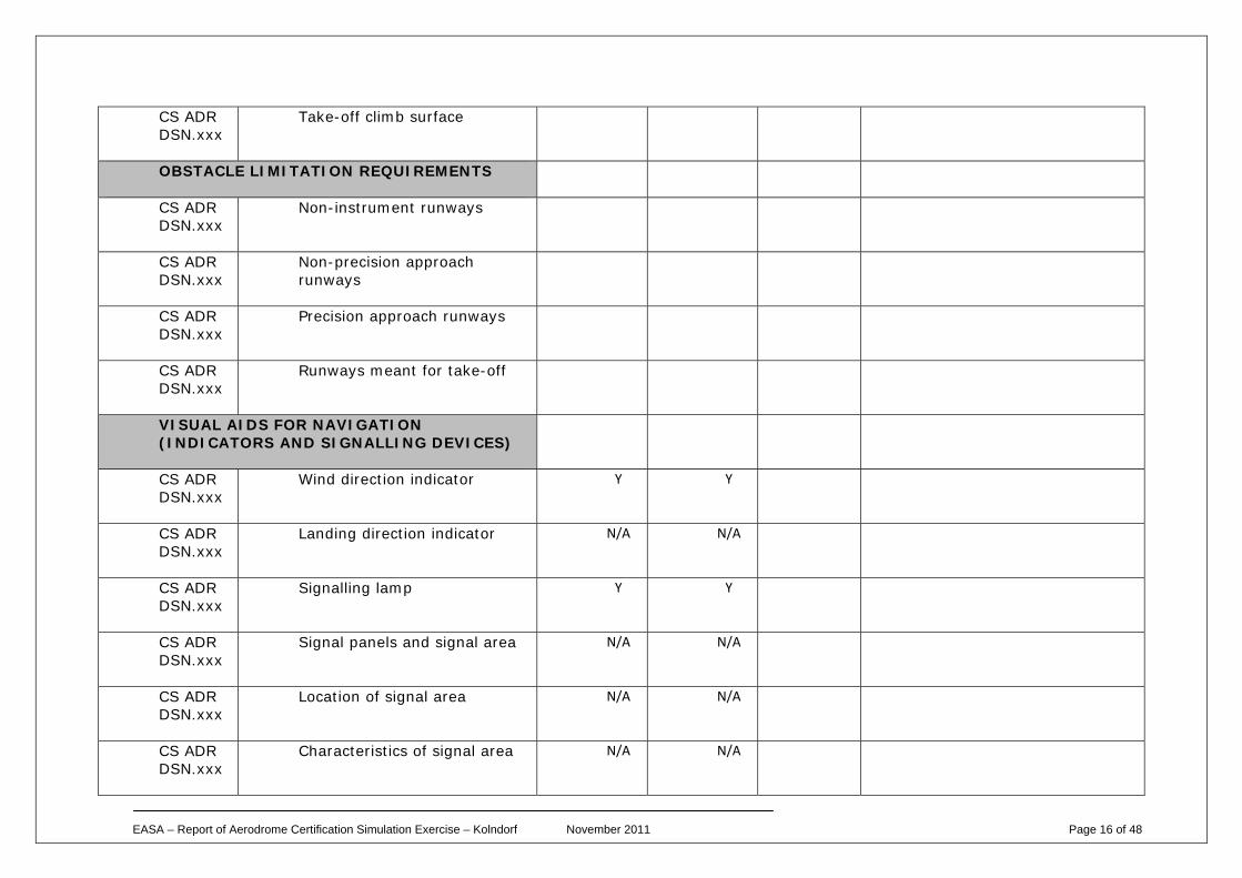
CS ADR DSN.xxx
Take-off climb surface
OBSTACLE LIMITATION REQUIREMENTS
CS ADR DSN.xxx
Non-instrument runways
CS ADR DSN.xxx
Non-precision approach runways
CS ADR DSN.xxx
Precision approach runways
CS ADR DSN.xxx
Runways meant for take-off
VISUAL AIDS FOR NAVIGATION (INDICATORS AND SIGNALLING DEVICES)
CS ADR DSN.xxx
Wind direction indicator Y Y
CS ADR DSN.xxx
Landing direction indicator N/A N/A
CS ADR DSN.xxx
Signalling lamp Y Y
CS ADR DSN.xxx
Signal panels and signal area N/A N/A
CS ADR DSN.xxx
Location of signal area N/A N/A
CS ADR DSN.xxx
Characteristics of signal area N/A N/A
EASA – Report of Aerodrome Certification Simulation Exercise – Kolndorf November 2011 Page 17 of 48
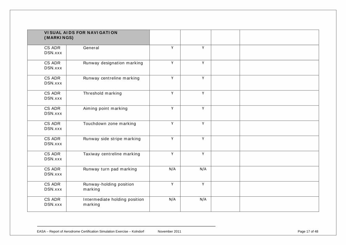
VISUAL AIDS FOR NAVIGATION (MARKINGS)
CS ADR DSN.xxx
General Y Y
CS ADR DSN.xxx
Runway designation marking Y Y
CS ADR DSN.xxx
Runway centreline marking Y Y
CS ADR DSN.xxx
Threshold marking Y Y
CS ADR DSN.xxx
Aiming point marking Y Y
CS ADR DSN.xxx
Touchdown zone marking Y Y
CS ADR DSN.xxx
Runway side stripe marking Y Y
CS ADR DSN.xxx
Taxiway centreline marking Y Y
CS ADR DSN.xxx
Runway turn pad marking N/A N/A
CS ADR DSN.xxx
Runway-holding position marking
Y Y
CS ADR DSN.xxx
Intermediate holding position marking
N/A N/A
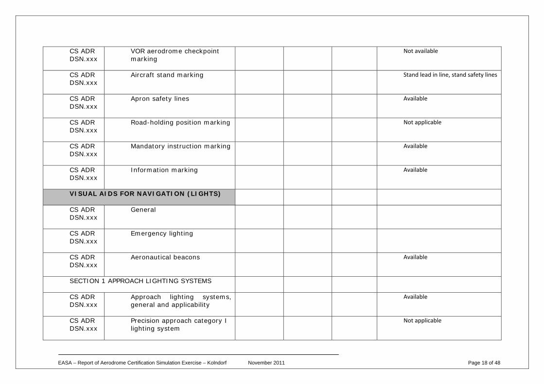
EASA – Report of Aerodrome Certification Simulation Exercise – Kolndorf November 2011 Page 18 of 48
CS ADR DSN.xxx
VOR aerodrome checkpoint marking
Not available
CS ADR DSN.xxx
Aircraft stand marking Stand lead in line, stand safety lines
CS ADR DSN.xxx
Apron safety lines Available
CS ADR DSN.xxx
Road-holding position marking Not applicable
CS ADR DSN.xxx
Mandatory instruction marking Available
CS ADR DSN.xxx
Information marking Available
VISUAL AIDS FOR NAVIGATION (LIGHTS)
CS ADR DSN.xxx
General
CS ADR DSN.xxx
Emergency lighting
CS ADR DSN.xxx
Aeronautical beacons Available
SECTION 1 APPROACH LIGHTING SYSTEMS
CS ADR DSN.xxx
Approach lighting systems, general and applicability
Available
CS ADR DSN.xxx
Precision approach category I lighting system
Not applicable
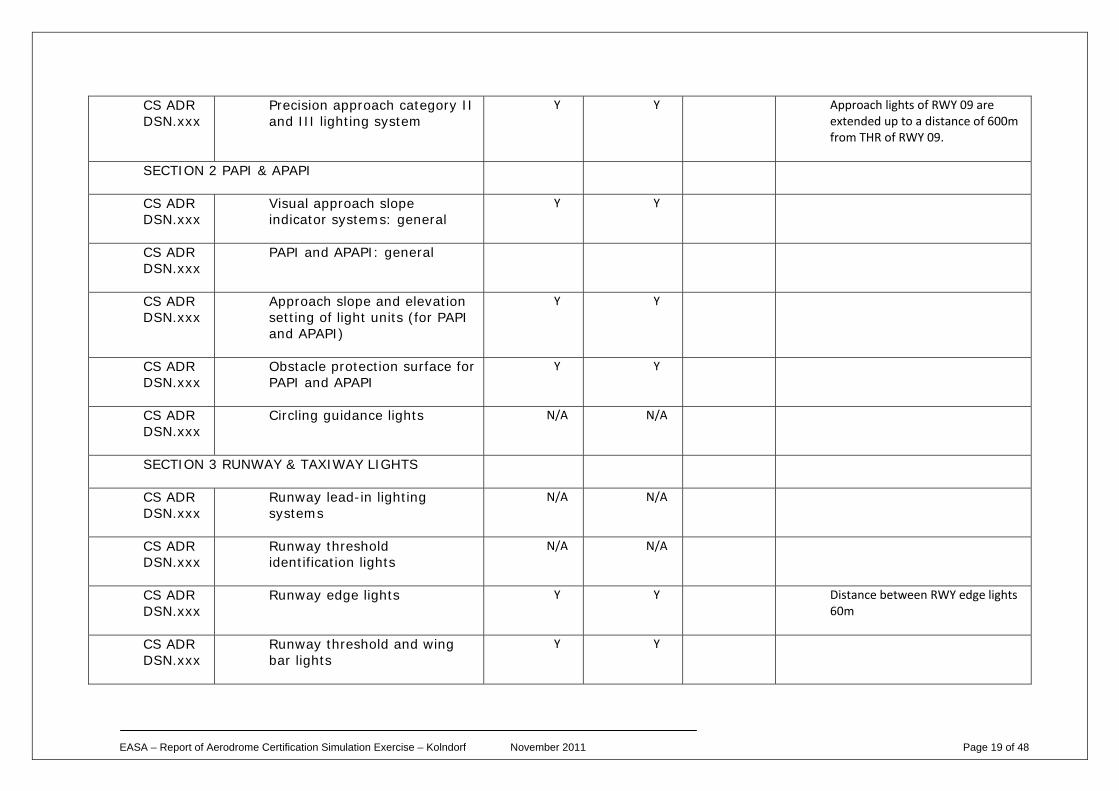
EASA – Report of Aerodrome Certification Simulation Exercise – Kolndorf November 2011 Page 19 of 48
CS ADR DSN.xxx
Precision approach category II and III lighting system
Y Y Approach lights of RWY 09 are extended up to a distance of 600m from THR of RWY 09.
SECTION 2 PAPI & APAPI
CS ADR DSN.xxx
Visual approach slope indicator systems: general
Y Y
CS ADR DSN.xxx
PAPI and APAPI: general
CS ADR DSN.xxx
Approach slope and elevation setting of light units (for PAPI and APAPI)
Y Y
CS ADR DSN.xxx
Obstacle protection surface for PAPI and APAPI
Y Y
CS ADR DSN.xxx
Circling guidance lights N/A N/A
SECTION 3 RUNWAY & TAXIWAY LIGHTS
CS ADR DSN.xxx
Runway lead-in lighting systems
N/A N/A
CS ADR DSN.xxx
Runway threshold identification lights
N/A N/A
CS ADR DSN.xxx
Runway edge lights Y Y Distance between RWY edge lights 60m
CS ADR DSN.xxx
Runway threshold and wing bar lights
Y Y
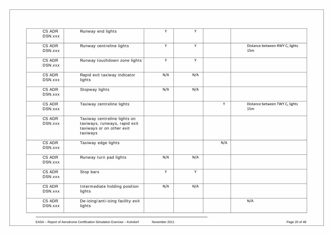
EASA – Report of Aerodrome Certification Simulation Exercise – Kolndorf November 2011 Page 20 of 48
CS ADR DSN.xxx
Runway end lights Y Y
CS ADR DSN.xxx
Runway centreline lights Y Y Distance between RWY CL lights 15m
CS ADR DSN.xxx
Runway touchdown zone lights Y Y
CS ADR DSN.xxx
Rapid exit taxiway indicator lights
N/A N/A
CS ADR DSN.xxx
Stopway lights N/A N/A
CS ADR DSN.xxx
Taxiway centreline lights Y Distance between TWY CL lights 15m
CS ADR DSN.xxx
Taxiway centreline lights on taxiways, runways, rapid exit taxiways or on other exit taxiways
CS ADR DSN.xxx
Taxiway edge lights N/A
CS ADR DSN.xxx
Runway turn pad lights N/A N/A
CS ADR DSN.xxx
Stop bars Y Y
CS ADR DSN.xxx
Intermediate holding position lights
N/A N/A
CS ADR DSN.xxx
De-icing/anti-icing facility exit lights
N/A
EASA – Report of Aerodrome Certification Simulation Exercise – Kolndorf November 2011 Page 21 of 48
CS ADR DSN.xxx
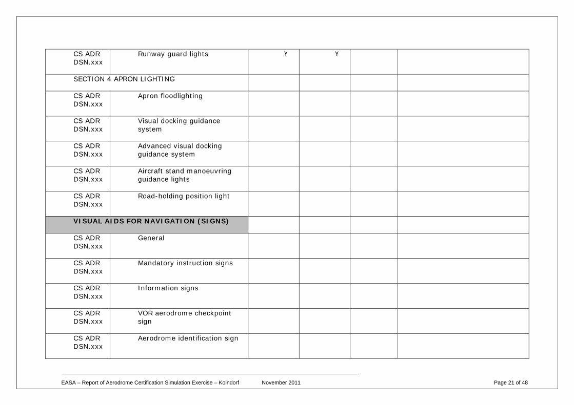
Runway guard lights Y Y
SECTION 4 APRON LIGHTING
CS ADR DSN.xxx
Apron floodlighting
CS ADR DSN.xxx
Visual docking guidance system
CS ADR DSN.xxx
Advanced visual docking guidance system
CS ADR DSN.xxx
Aircraft stand manoeuvring guidance lights
CS ADR DSN.xxx
Road-holding position light
VISUAL AIDS FOR NAVIGATION (SIGNS)
CS ADR DSN.xxx
General
CS ADR DSN.xxx
Mandatory instruction signs
CS ADR DSN.xxx
Information signs
CS ADR DSN.xxx
VOR aerodrome checkpoint sign
CS ADR DSN.xxx
Aerodrome identification sign
EASA – Report of Aerodrome Certification Simulation Exercise – Kolndorf November 2011 Page 22 of 48
CS ADR DSN.xxx
Aircraft stand identification signs
CS ADR DSN.xxx
Road-holding position sign
VISUAL AIDS FOR NAVIGATION (MARKERS)
CS ADR DSN.xxx
General
CS ADR DSN.xxx
Unpaved runway edge markers
CS ADR DSN.xxx
Stopway edge markers
CS ADR DSN.xxx
Edge markers for snow-covered runways
CS ADR DSN.xxx
Taxiway edge markers
CS ADR DSN.xxx
Taxiway centreline markers
CS ADR DSN.xxx
Unpaved taxiway edge markers
CS ADR DSN.xxx
Boundary markers
VISUAL AIDS FOR DENOTING OBSTACLES
CS ADR DSN.xxx
Objects to be marked and/or lighted
EASA – Report of Aerodrome Certification Simulation Exercise – Kolndorf November 2011 Page 23 of 48
CS ADR DSN.xxx
Marking of objects
CS ADR DSN.xxx
Lighting of objects
CS ADR DSN.xxx
Wind turbines
VISUAL AIDS FOR DENOTING RESTRICTED USE AREAS
CS ADR DSN.xxx
Closed runways and taxiways, or parts thereof
CS ADR DSN.xxx
Non-load-bearing surfaces
CS ADR DSN.xxx
Pre-threshold area
CS ADR DSN.xxx
Unserviceable areas
ELECTRICAL SYSTEMS
CS ADR DSN.xxx
Electrical power supply systems for air navigation facilities
CS ADR DSN.xxx
Visual aids
CS ADR DSN.xxx
System design
EASA – Report of Aerodrome Certification Simulation Exercise – Kolndorf November 2011 Page 24 of 48
CS ADR DSN.xxx
Monitoring
AERODROME OPERATIONAL SERVICES, EQUIPMENT AND INSTALLATION
CS ADR DSN.xxx
Emergency access roads - location and construction spec, signs, markings, etc.
CS ADR DSN.xxx
Fire stations - location
CS ADR DSN.xxx
Siting of equipment and installations on operational areas - location, frangibility, etc.
CS ADR DSN.xxx
Fencing
CS ADR DSN.xxx
Security lighting - location
EASA – Report of Aerodrome Certification Simulation Exercise – Kolndorf November 2011 Page 25 of 48
Attachment B
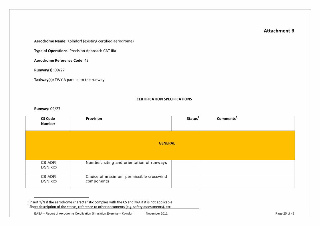
Aerodrome Name: Kolndorf (existing certified aerodrome)
Type of Operations: Precision Approach CAT IIIa
Aerodrome Reference Code: 4E
Runway(s): 09/27
Taxiway(s): TWY A parallel to the runway
CERTIFICATION SPECIFICATIONS
Runway: 09/27
CS Code Number
Provision Status1 Comments2
GENERAL
CS ADR DSN.xxx
Number, siting and orientation of runways
CS ADR DSN.xxx
Choice of maximum permissible crosswind components
1 Insert Y/N if the aerodrome characteristic complies with the CS and N/A if it is not applicable 2 Short description of the status, reference to other documents (e.g. safety assessments), etc.
EASA – Report of Aerodrome Certification Simulation Exercise – Kolndorf November 2011 Page 26 of 48
CS ADR DSN.xxx
Data to be used
CS ADR DSN.xxx
Runway threshold Y
CS ADR DSN.xxx
Actual length of the runway (m) Y
CS ADR DSN.xxx
Runways with stopways or clearways N/A
CS ADR DSN.xxx
Width of runways Y
CS ADR DSN.xxx
Minimum distance between parallel non instrument runways
N/A
CS ADR DSN.xxx
Minimum distance between parallel instrument runways
N/A
CS ADR DSN.xxx
Longitudinal slopes of runways Y
CS ADR DSN.xxx
Longitudinal runway slope changes Y
CS ADR DSN.xxx
Sight distance Y
CS ADR DSN.xxx
Distance between slope changes Y
CS ADR DSN.xxx
Transverse slopes Y
EASA – Report of Aerodrome Certification Simulation Exercise – Kolndorf November 2011 Page 27 of 48
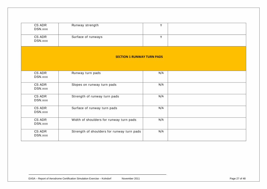
CS ADR DSN.xxx
Runway strength Y
CS ADR DSN.xxx
Surface of runways Y
SECTION 1 RUNWAY TURN PADS
CS ADR DSN.xxx
Runway turn pads N/A
CS ADR DSN.xxx
Slopes on runway turn pads N/A
CS ADR DSN.xxx
Strength of runway turn pads N/A
CS ADR DSN.xxx
Surface of runway turn pads N/A
CS ADR DSN.xxx
Width of shoulders for runway turn pads N/A
CS ADR DSN.xxx
Strength of shoulders for runway turn pads N/A
EASA – Report of Aerodrome Certification Simulation Exercise – Kolndorf November 2011 Page 28 of 48
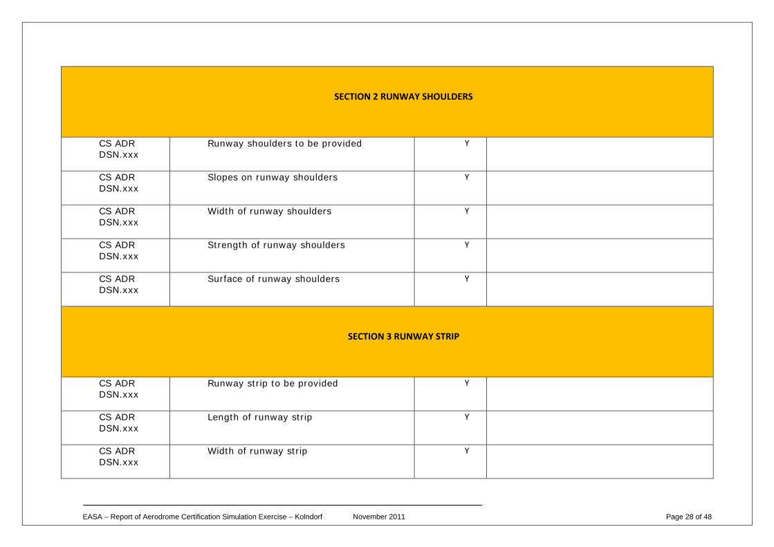
SECTION 2 RUNWAY SHOULDERS
CS ADR DSN.xxx
Runway shoulders to be provided Y
CS ADR DSN.xxx
Slopes on runway shoulders Y
CS ADR DSN.xxx
Width of runway shoulders Y
CS ADR DSN.xxx
Strength of runway shoulders Y
CS ADR DSN.xxx
Surface of runway shoulders Y
SECTION 3 RUNWAY STRIP
CS ADR DSN.xxx
Runway strip to be provided Y
CS ADR DSN.xxx
Length of runway strip Y
CS ADR DSN.xxx
Width of runway strip Y
EASA – Report of Aerodrome Certification Simulation Exercise – Kolndorf November 2011 Page 29 of 48
CS ADR DSN.xxx
Objects on runway strips Y
CS ADR DSN.xxx
Non-precision approach and non-instrument runway strips
N/A
CS ADR DSN.xxx
Grading of runway strips Y
CS ADR DSN.xxx
Longitudinal Slopes on runway strips Y
CS ADR DSN.xxx
Transverse Slopes on runway strips Y
CS ADR DSN.xxx
Strength of runway strips
CS ADR DSN.xxx
Longitudinal slope changes on runway strip
SECTION 4 RUNWAY END SAFETY AREA
CS ADR DSN.xxx
Runway End Safety Areas Y
CS ADR DSN.xxx
Dimensions of runway end safety areas N Length of RESA on RWY 09 60m, ELOS by having installed an arresting system. Details in Doc. Ref: 123/30‐06‐2010.
CS ADR DSN.xxx
Objects on runway end safety areas Y
EASA – Report of Aerodrome Certification Simulation Exercise – Kolndorf November 2011 Page 30 of 48
CS ADR DSN.xxx
Clearing and grading of runway end safety areas
Y
CS ADR DSN.xxx
Slopes on runway end safety areas Y
CS ADR DSN.xxx
Strength of runway end safety areas Y
Runway3: …….
3 Repeat the table for every available runway
EASA – Report of Aerodrome Certification Simulation Exercise – Kolndorf November 2011 Page 31 of 48
Taxiways4
CS Code Number
Provision Status Comments
CS ADR DSN.xxx
Taxiways General Y
CS ADR DSN.xxx
Width of Taxiways Y
CS ADR DSN.xxx
Curves on taxiways Y
CS ADR DSN.xxx
Junction and intersection of taxiways Y
CS ADR DSN.xxx
Taxiway minimum separation distance N Distance between TWY CL and RWY CL 160m
Restrictions:
Movement of aircraft is not allowed on the TWY when the runway is contaminated and crosswind component is more than 10kts, while arriving aircraft is on final. Details in Doc.125/1990 (Special Condition).
CS ADR DSN.xxx
Longitudinal slopes on taxiways N Slope 1.7% due to topographical features (special condition).
CS ADR DSN.xxx
Longitudinal slope changes on taxiways Y
4 This section should not be completed for every taxiway. If a taxiway is not meeting a particular CS, details should be given in the ‘comments’ column.
EASA – Report of Aerodrome Certification Simulation Exercise – Kolndorf November 2011 Page 32 of 48
CS ADR DSN.xxx
Sight distance of taxiways Y
CS ADR DSN.xxx
Transverse slopes on taxiways Y
CS ADR DSN.xxx
Strength of taxiways Y
CS ADR DSN.xxx
Surface of taxiways Y
CS ADR DSN.xxx
Rapid exit taxiways N/A
CS ADR DSN.xxx
Taxiways on bridges N/A
CS ADR DSN.xxx
Taxiway shoulders Y
CS ADR DSN.xxx
Taxiway Strip N Industrial Building infringes taxiway strip by 3.5m (DAAD)
CS ADR DSN.xxx
Width of taxiway strips Y
CS ADR DSN.xxx
Objects on taxiway strips Y
CS ADR DSN.xxx
Grading of taxiway strips Y
CS ADR DSN.xxx
Slopes on taxiway strips Y
EASA – Report of Aerodrome Certification Simulation Exercise – Kolndorf November 2011 Page 33 of 48
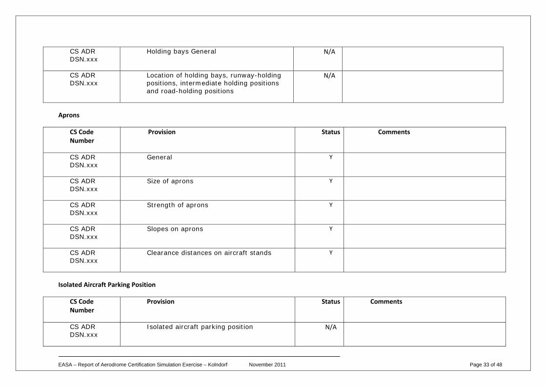
CS ADR DSN.xxx
Holding bays General N/A
CS ADR DSN.xxx
Location of holding bays, runway-holding positions, intermediate holding positions and road-holding positions
N/A
Aprons
CS Code Number
Provision Status Comments
CS ADR DSN.xxx
General Y
CS ADR DSN.xxx
Size of aprons Y
CS ADR DSN.xxx
Strength of aprons Y
CS ADR DSN.xxx
Slopes on aprons Y
CS ADR DSN.xxx
Clearance distances on aircraft stands Y
Isolated Aircraft Parking Position
CS Code Number
Provision Status Comments
CS ADR DSN.xxx
Isolated aircraft parking position N/A
EASA – Report of Aerodrome Certification Simulation Exercise – Kolndorf November 2011 Page 34 of 48
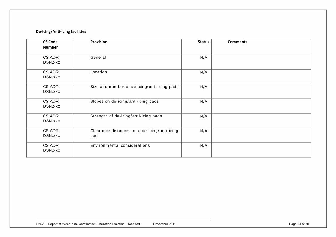
De‐icing/Anti‐icing facilities
CS Code Number
Provision Status Comments
CS ADR DSN.xxx
General N/A
CS ADR DSN.xxx
Location N/A
CS ADR DSN.xxx
Size and number of de-icing/anti-icing pads N/A
CS ADR DSN.xxx
Slopes on de-icing/anti-icing pads N/A
CS ADR DSN.xxx
Strength of de-icing/anti-icing pads N/A
CS ADR DSN.xxx
Clearance distances on a de-icing/anti-icing pad
N/A
CS ADR DSN.xxx
Environmental considerations N/A
EASA – Report of Aerodrome Certification Simulation Exercise – Kolndorf November 2011 Page 35 of 48
Obstacles
CS Code Number
Provision Status Comments
SECTION 1 OBSTACLE LIMITATION SURFACES
CS ADR DSN.xxx
Outer horizontal surface
CS ADR DSN.xxx
Conical surface Y
CS ADR DSN.xxx
Inner horizontal surface Y
CS ADR DSN.xxx
Approach surface Y
CS ADR DSN.xxx
Inner approach surface Y
CS ADR DSN.xxx
Transitional surface Y
CS ADR DSN.xxx
Inner transitional surface Y
CS ADR DSN.xxx
Balked landing surface Y
CS ADR DSN.xxx
Take-off climb surface Y
EASA – Report of Aerodrome Certification Simulation Exercise – Kolndorf November 2011 Page 36 of 48
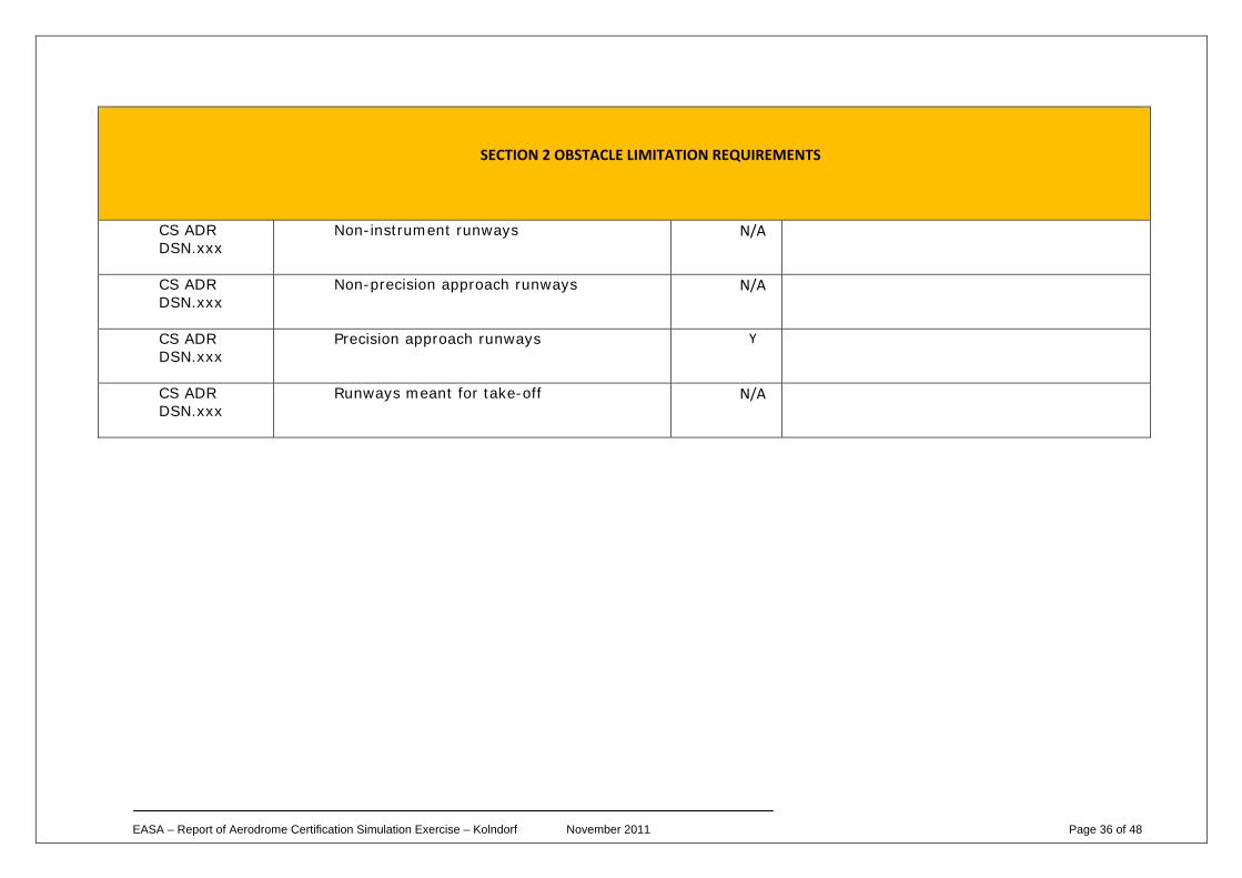
SECTION 2 OBSTACLE LIMITATION REQUIREMENTS
CS ADR DSN.xxx
Non-instrument runways N/A
CS ADR DSN.xxx
Non-precision approach runways N/A
CS ADR DSN.xxx
Precision approach runways Y
CS ADR DSN.xxx
Runways meant for take-off N/A
EASA – Report of Aerodrome Certification Simulation Exercise – Kolndorf November 2011 Page 37 of 48
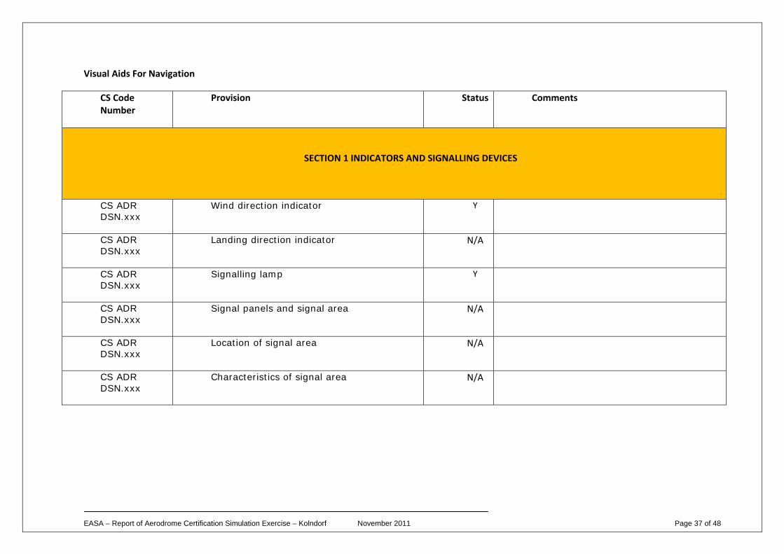
Visual Aids For Navigation
CS Code Number
Provision Status Comments
SECTION 1 INDICATORS AND SIGNALLING DEVICES
CS ADR DSN.xxx
Wind direction indicator Y
CS ADR DSN.xxx
Landing direction indicator N/A
CS ADR DSN.xxx
Signalling lamp Y
CS ADR DSN.xxx
Signal panels and signal area N/A
CS ADR DSN.xxx
Location of signal area N/A
CS ADR DSN.xxx
Characteristics of signal area N/A
EASA – Report of Aerodrome Certification Simulation Exercise – Kolndorf November 2011 Page 38 of 48
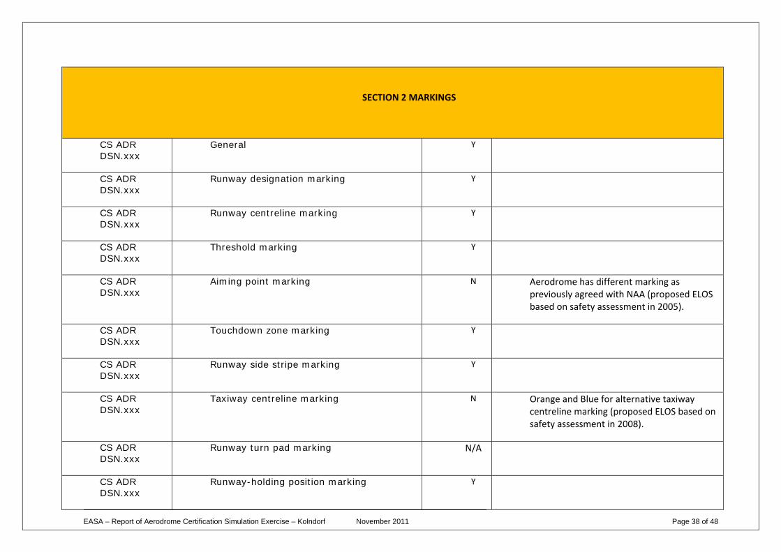
SECTION 2 MARKINGS
CS ADR DSN.xxx
General Y
CS ADR DSN.xxx
Runway designation marking Y
CS ADR DSN.xxx
Runway centreline marking Y
CS ADR DSN.xxx
Threshold marking Y
CS ADR DSN.xxx
Aiming point marking N Aerodrome has different marking as previously agreed with NAA (proposed ELOS based on safety assessment in 2005).
CS ADR DSN.xxx
Touchdown zone marking Y
CS ADR DSN.xxx
Runway side stripe marking Y
CS ADR DSN.xxx
Taxiway centreline marking N Orange and Blue for alternative taxiway centreline marking (proposed ELOS based on safety assessment in 2008).
CS ADR DSN.xxx
Runway turn pad marking N/A
CS ADR DSN.xxx
Runway-holding position marking Y
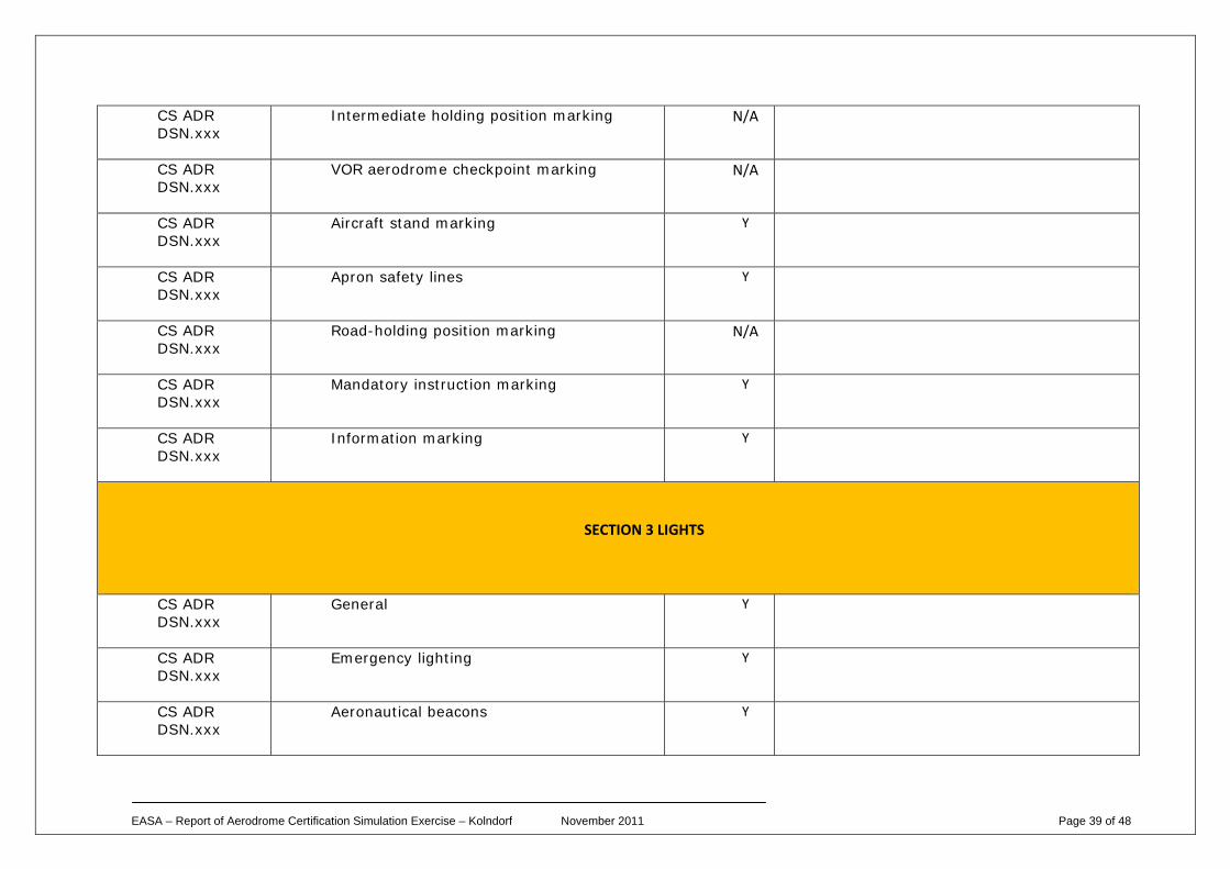
EASA – Report of Aerodrome Certification Simulation Exercise – Kolndorf November 2011 Page 39 of 48
CS ADR DSN.xxx
Intermediate holding position marking N/A
CS ADR DSN.xxx
VOR aerodrome checkpoint marking N/A
CS ADR DSN.xxx
Aircraft stand marking Y
CS ADR DSN.xxx
Apron safety lines Y
CS ADR DSN.xxx
Road-holding position marking N/A
CS ADR DSN.xxx
Mandatory instruction marking Y
CS ADR DSN.xxx
Information marking Y
SECTION 3 LIGHTS
CS ADR DSN.xxx
General Y
CS ADR DSN.xxx
Emergency lighting Y
CS ADR DSN.xxx
Aeronautical beacons Y
EASA – Report of Aerodrome Certification Simulation Exercise – Kolndorf November 2011 Page 40 of 48
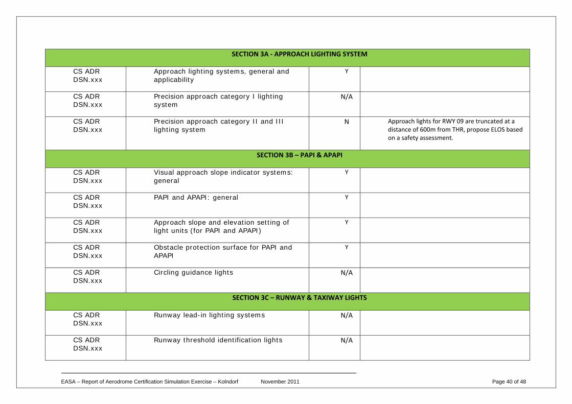
SECTION 3A ‐ APPROACH LIGHTING SYSTEM
CS ADR DSN.xxx
Approach lighting systems, general and applicability
Y
CS ADR DSN.xxx
Precision approach category I lighting system
N/A
CS ADR DSN.xxx
Precision approach category II and III lighting system
N Approach lights for RWY 09 are truncated at a distance of 600m from THR, propose ELOS based on a safety assessment.
SECTION 3B – PAPI & APAPI
CS ADR DSN.xxx
Visual approach slope indicator systems: general
Y
CS ADR DSN.xxx
PAPI and APAPI: general Y
CS ADR DSN.xxx
Approach slope and elevation setting of light units (for PAPI and APAPI)
Y
CS ADR DSN.xxx
Obstacle protection surface for PAPI and APAPI
Y
CS ADR DSN.xxx
Circling guidance lights N/A
SECTION 3C – RUNWAY & TAXIWAY LIGHTS
CS ADR DSN.xxx
Runway lead-in lighting systems N/A
CS ADR DSN.xxx
Runway threshold identification lights N/A
EASA – Report of Aerodrome Certification Simulation Exercise – Kolndorf November 2011 Page 41 of 48
CS ADR DSN.xxx
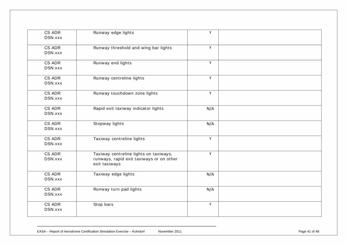
Runway edge lights Y
CS ADR DSN.xxx
Runway threshold and wing bar lights Y
CS ADR DSN.xxx
Runway end lights Y
CS ADR DSN.xxx
Runway centreline lights Y
CS ADR DSN.xxx
Runway touchdown zone lights Y
CS ADR DSN.xxx
Rapid exit taxiway indicator lights N/A
CS ADR DSN.xxx
Stopway lights N/A
CS ADR DSN.xxx
Taxiway centreline lights Y
CS ADR DSN.xxx
Taxiway centreline lights on taxiways, runways, rapid exit taxiways or on other exit taxiways
Y
CS ADR DSN.xxx
Taxiway edge lights N/A
CS ADR DSN.xxx
Runway turn pad lights N/A
CS ADR DSN.xxx
Stop bars Y
EASA – Report of Aerodrome Certification Simulation Exercise – Kolndorf November 2011 Page 42 of 48
CS ADR DSN.xxx
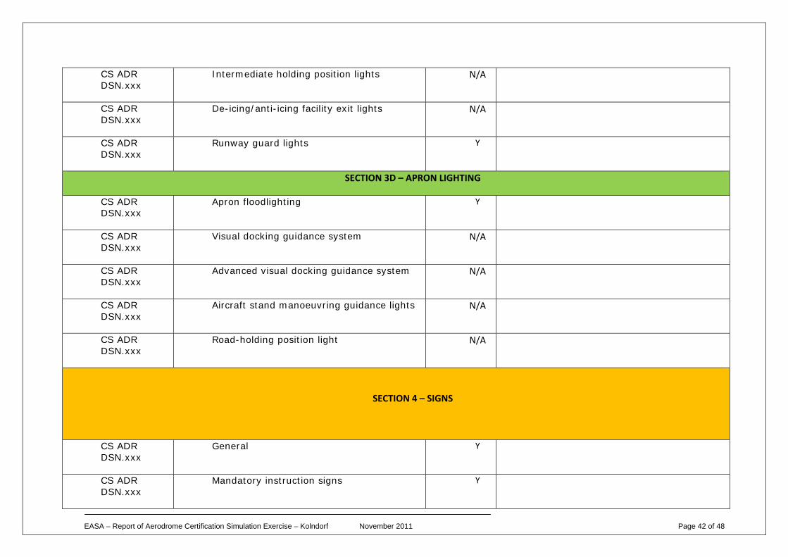
Intermediate holding position lights N/A
CS ADR DSN.xxx
De-icing/anti-icing facility exit lights N/A
CS ADR DSN.xxx
Runway guard lights Y
SECTION 3D – APRON LIGHTING
CS ADR DSN.xxx
Apron floodlighting Y
CS ADR DSN.xxx
Visual docking guidance system N/A
CS ADR DSN.xxx
Advanced visual docking guidance system N/A
CS ADR DSN.xxx
Aircraft stand manoeuvring guidance lights N/A
CS ADR DSN.xxx
Road-holding position light N/A
SECTION 4 – SIGNS
CS ADR DSN.xxx
General Y
CS ADR DSN.xxx
Mandatory instruction signs Y
EASA – Report of Aerodrome Certification Simulation Exercise – Kolndorf November 2011 Page 43 of 48
CS ADR DSN.xxx
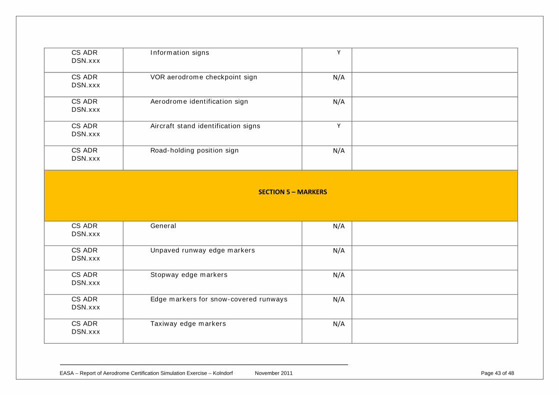
Information signs Y
CS ADR DSN.xxx
VOR aerodrome checkpoint sign N/A
CS ADR DSN.xxx
Aerodrome identification sign N/A
CS ADR DSN.xxx
Aircraft stand identification signs Y
CS ADR DSN.xxx
Road-holding position sign N/A
SECTION 5 – MARKERS
CS ADR DSN.xxx
General N/A
CS ADR DSN.xxx
Unpaved runway edge markers N/A
CS ADR DSN.xxx
Stopway edge markers N/A
CS ADR DSN.xxx
Edge markers for snow-covered runways N/A
CS ADR DSN.xxx
Taxiway edge markers N/A
EASA – Report of Aerodrome Certification Simulation Exercise – Kolndorf November 2011 Page 44 of 48
CS ADR DSN.xxx
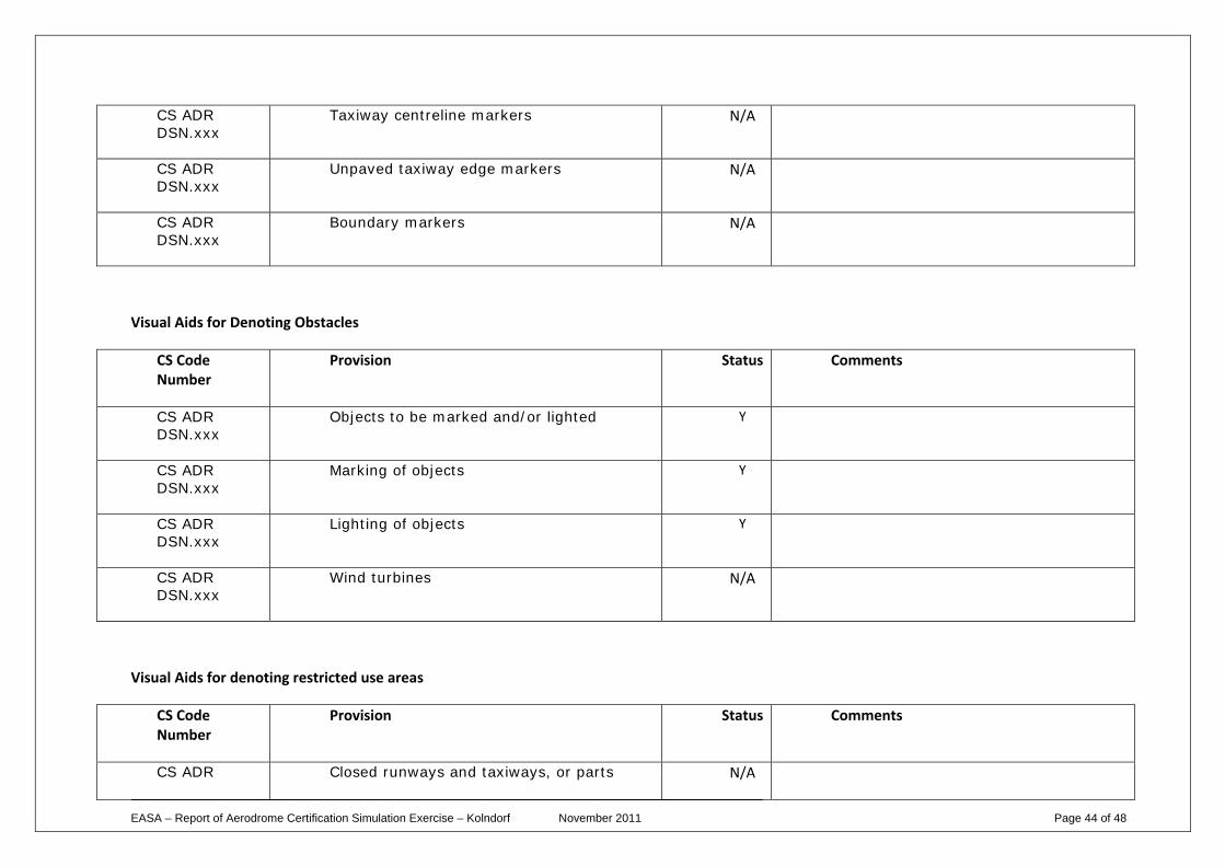
Taxiway centreline markers N/A
CS ADR DSN.xxx
Unpaved taxiway edge markers N/A
CS ADR DSN.xxx
Boundary markers N/A
Visual Aids for Denoting Obstacles
CS Code Number
Provision Status Comments
CS ADR DSN.xxx
Objects to be marked and/or lighted Y
CS ADR DSN.xxx
Marking of objects Y
CS ADR DSN.xxx
Lighting of objects Y
CS ADR DSN.xxx
Wind turbines N/A
Visual Aids for denoting restricted use areas
CS Code Number
Provision Status Comments
CS ADR Closed runways and taxiways, or parts N/A
EASA – Report of Aerodrome Certification Simulation Exercise – Kolndorf November 2011 Page 45 of 48
DSN.xxx thereof
CS ADR DSN.xxx
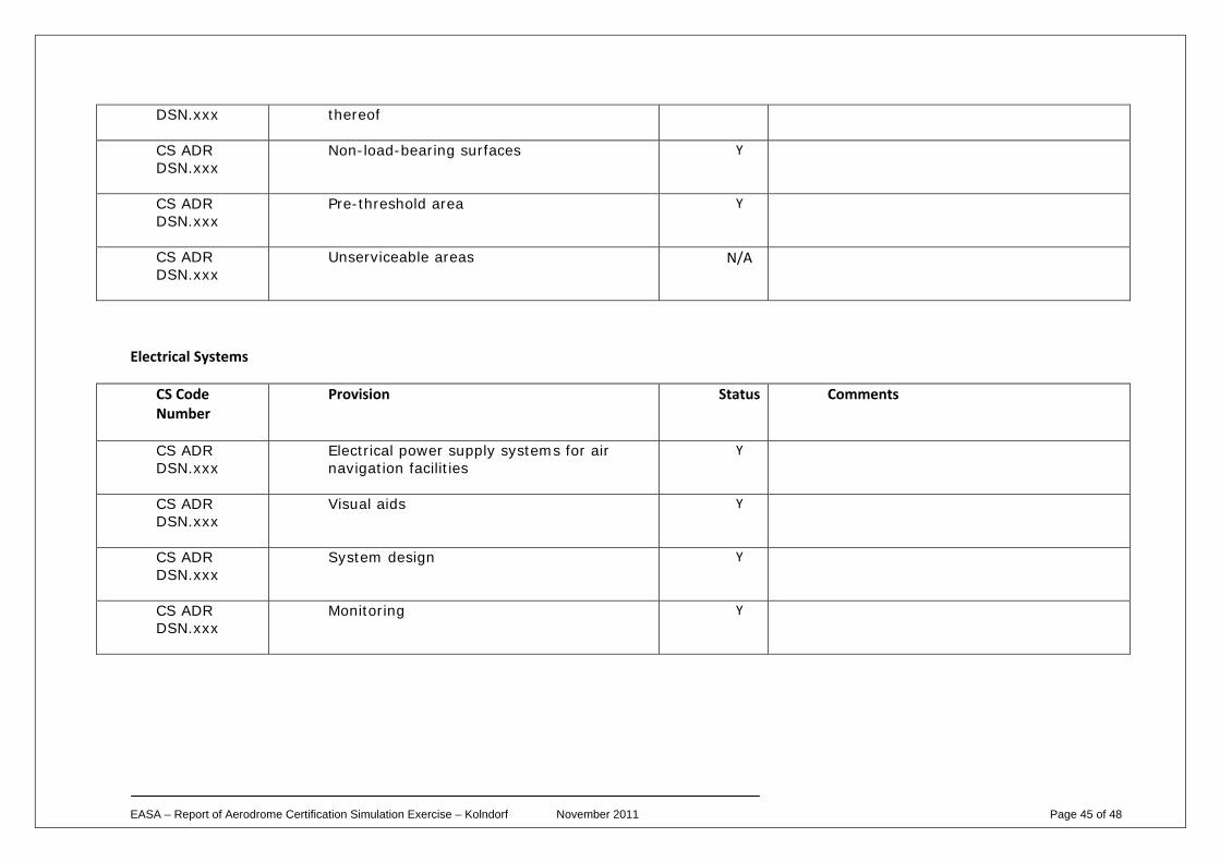
Non-load-bearing surfaces Y
CS ADR DSN.xxx
Pre-threshold area Y
CS ADR DSN.xxx
Unserviceable areas N/A
Electrical Systems
CS Code Number
Provision Status Comments
CS ADR DSN.xxx
Electrical power supply systems for air navigation facilities
Y
CS ADR DSN.xxx
Visual aids Y
CS ADR DSN.xxx
System design Y
CS ADR DSN.xxx
Monitoring Y
EASA – Report of Aerodrome Certification Simulation Exercise – Kolndorf November 2011 Page 46 of 48
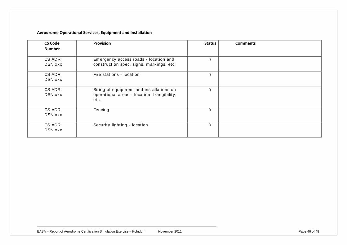
Aerodrome Operational Services, Equipment and Installation
CS Code Number
Provision Status Comments
CS ADR DSN.xxx
Emergency access roads - location and construction spec, signs, markings, etc.
Y
CS ADR DSN.xxx
Fire stations - location Y
CS ADR DSN.xxx
Siting of equipment and installations on operational areas - location, frangibility, etc.
Y
CS ADR DSN.xxx
Fencing Y
CS ADR DSN.xxx
Security lighting - location Y
EASA – Report of Aerodrome Certification Simulation Exercise – Kolndorf November 2011 Page 47 of 48
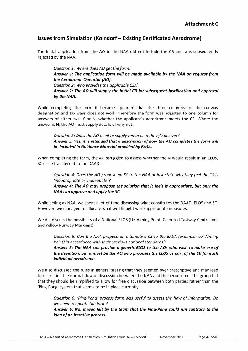
Attachment C Issues from Simulation (Kolndorf – Existing Certificated Aerodrome) The initial application from the AO to the NAA did not include the CB and was subsequently rejected by the NAA.
Question 1: Where does AO get the form? Answer 1: The application form will be made available by the NAA on request from the Aerodrome Operator (AO). Question 2: Who provides the applicable CSs? Answer 2: The AO will supply the initial CB for subsequent justification and approval by the NAA.
While completing the form it became apparent that the three columns for the runway designation and taxiways does not work, therefore the form was adjusted to one column for answers of either n/a, Y or N, whether the applicant’s aerodrome meets the CS. Where the answer is N, the AO must supply details of why not.
Question 3: Does the AO need to supply remarks to the n/a answer? Answer 3: Yes, it is intended that a description of how the AO completes the form will be included in Guidance Material provided by EASA.
When completing the form, the AO struggled to assess whether the N would result in an ELOS, SC or be transferred to the DAAD.
Question 4: Does the AO propose an SC to the NAA or just state why they feel the CS is ‘inappropriate or inadequate’? Answer 4: The AO may propose the solution that it feels is appropriate, but only the NAA can approve and apply the SC.
While acting as NAA, we spent a lot of time discussing what constitutes the DAAD, ELOS and SC. However, we managed to allocate what we thought were appropriate measures. We did discuss the possibility of a National ELOS (UK Aiming Point, Coloured Taxiway Centrelines and Yellow Runway Markings).
Question 5: Can the NAA propose an alternative CS to the EASA (example: UK Aiming Point) in accordance with their previous national standards? Answer 5: The NAA can provide a generic ELOS to the AOs who wish to make use of the deviation, but it must be the AO who proposes the ELOS as part of the CB for each individual aerodrome.
We also discussed the rules in general stating that they seemed over prescriptive and may lead to restricting the normal flow of discussion between the NAA and the aerodrome. The group felt that they should be simplified to allow for free discussion between both parties rather than the ‘Ping‐Pong’ system that seems to be in place currently.
Question 6: ‘Ping‐Pong’ process form was useful to assess the flow of information. Do we need to update the form? Answer 6: No, it was felt by the team that the Ping‐Pong could run contrary to the idea of an iterative process.
EASA – Report of Aerodrome Certification Simulation Exercise – Kolndorf November 2011 Page 48 of 48
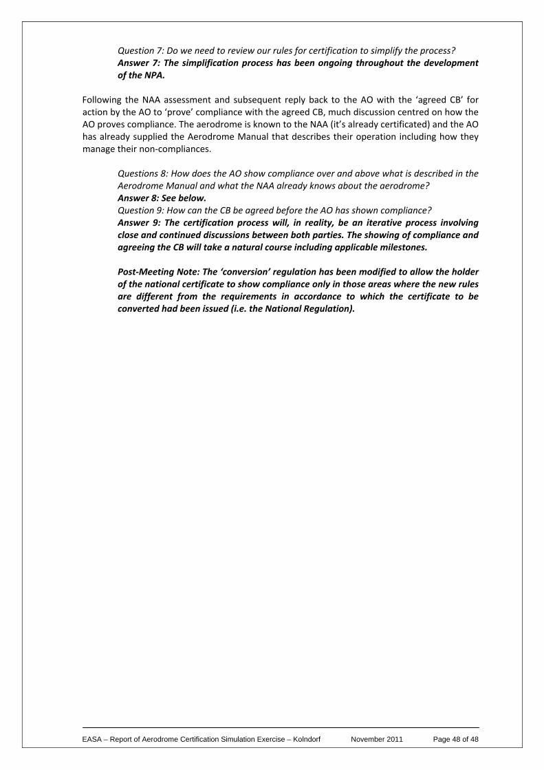
Question 7: Do we need to review our rules for certification to simplify the process? Answer 7: The simplification process has been ongoing throughout the development of the NPA.
Following the NAA assessment and subsequent reply back to the AO with the ‘agreed CB’ for action by the AO to ‘prove’ compliance with the agreed CB, much discussion centred on how the AO proves compliance. The aerodrome is known to the NAA (it’s already certificated) and the AO has already supplied the Aerodrome Manual that describes their operation including how they manage their non‐compliances.
Questions 8: How does the AO show compliance over and above what is described in the Aerodrome Manual and what the NAA already knows about the aerodrome? Answer 8: See below. Question 9: How can the CB be agreed before the AO has shown compliance? Answer 9: The certification process will, in reality, be an iterative process involving close and continued discussions between both parties. The showing of compliance and agreeing the CB will take a natural course including applicable milestones. Post‐Meeting Note: The ‘conversion’ regulation has been modified to allow the holder of the national certificate to show compliance only in those areas where the new rules are different from the requirements in accordance to which the certificate to be converted had been issued (i.e. the National Regulation).
Top Related