


Languages
Pages
Legal

October 7-8, 2008Return to Session Directory
THRUSTERS
Reliable Prediction of Steerable Thruster Systems Based on Condition Measurements
Daniël Soute, Teus van Beek, Jeroen van Keep Wärtsilä Ship Power
.
2 © Wärtsilä D.Soute, 8th October 2008
0. Agenda
1. Introduction2. The thruster system3. Design aspect of mechanical systems4. Reliability of steerable thruster based on field analysis5. Conclusions
3 © Wärtsilä D.Soute, 8th October 2008
1. Introduction
Reliability is the ability of the equipment unit to perform its stated duty without a forced (unscheduled) outage in a given period of time
By William E Forsthoffer (Reliability optimization through component condition monitoring and root cause analysis)

4 © Wärtsilä D.Soute, 8th October 2008
1. Introduction
• ScopeCombined use of CMS and reliability engineering for improvement of total life cycle operation
• Why is it importantBetter understanding of system and component characteristics, based on service measurementsFind underlying factors for improvement Provide effective ways to support expected system behavior Serve as a basis for maintenance programs and life cycle costs
• What do we want to achieveBetter prediction of maintenance, reliability and availabilityBetter design for improved overall performance and reduced maintenanceImproved availabilityBetter understanding of system behavior

5 © Wärtsilä D.Soute, 8th October 2008
2. Thruster System What can go wrong
• Seal damage: water content in lub. oil reduces the life time of bearings and gears with 50%
• Inadequate lubrication: due to late filter / oil change• Overloading of the thruster• External impacts
• Eventually this leads to early wear of gears and bearings• Wear particles spread through the unit and affect other “healthy” components
THE HEALTH OF THE THRUSTER SLOWLY BUT STEADILY DETERIORATES

6 © Wärtsilä D.Soute, 8th October 2008
2. Thruster System Results of malfunctions
• Unplanned maintenance / repairs• Replacement parts• Loss of redundancy (Class)• Docking

7 © Wärtsilä D.Soute, 8th October 2008
2. Thruster System Development CMS
Today
Alarms
• pressure• temperature• level
Tomorrow
Monitoring
Early detection of deteriorating components:
• vibrations• moisture• particles
Future
Diagnostics / prognostics
• combine signals, remaining lifetime• database
Result -> signals:• detect early changes• make trend line

8 © Wärtsilä D.Soute, 8th October 2008
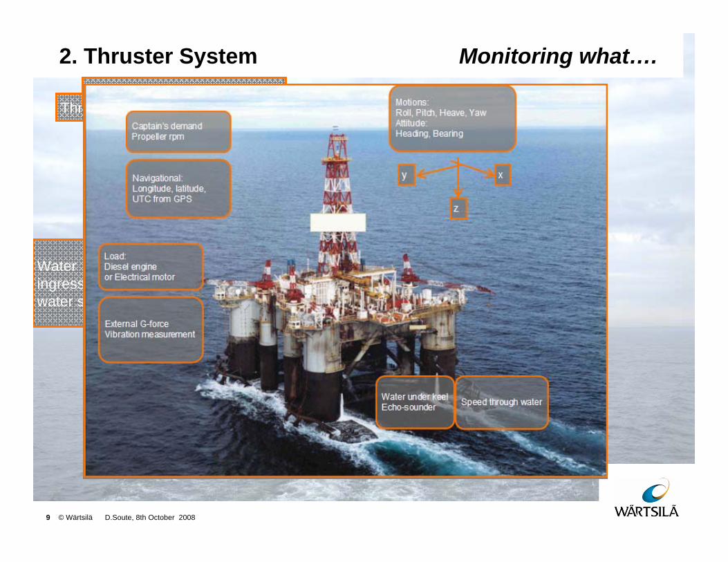
2. Thruster System Monitoring what….
Water ingress, by water sensor
Particles in oil, by particle counter
Vibrations of bearings and gears by accelerometers
RPM
Thruster parameters
9 © Wärtsilä D.Soute, 8th October 2008
2. Thruster System Monitoring what….
Water ingress, by water sensor
Particles in oil, by particle counter
Vibrations of bearings and gears by accelerometers
RPM
Thruster parametersOperational events

10 © Wärtsilä D.Soute, 8th October 2008
3. Design aspects of mechanical systems
Failure Mode Effect and Criticality Assessment (FMECA):
• Clear vision on the various ways equipment may fail -> intrinsic and exogenous failure processes.
• Room for subjective assessment of criticality and the effect of maintenance interventions.
Quantitative decision support:
• Quantified analysis of the various maintenance strategies:Functional failures and repair activities as realisations of chance processes.Characterised by a probability distribution (mean and spread in failure and repair time).

11 © Wärtsilä D.Soute, 8th October 2008
3. Design aspects of mechanical systems
• System• Assembly• Component
Functional decomposition
Evaluation of each failure
mode
Compensating provision and corrective action Address criticality
• Cause• Effect
LocalSystem
• Redundancy• Material, hours
• Probability• Severity
Set-up FMECA
12 © Wärtsilä D.Soute, 8th October 2008
3. Design aspects of mechanical systems
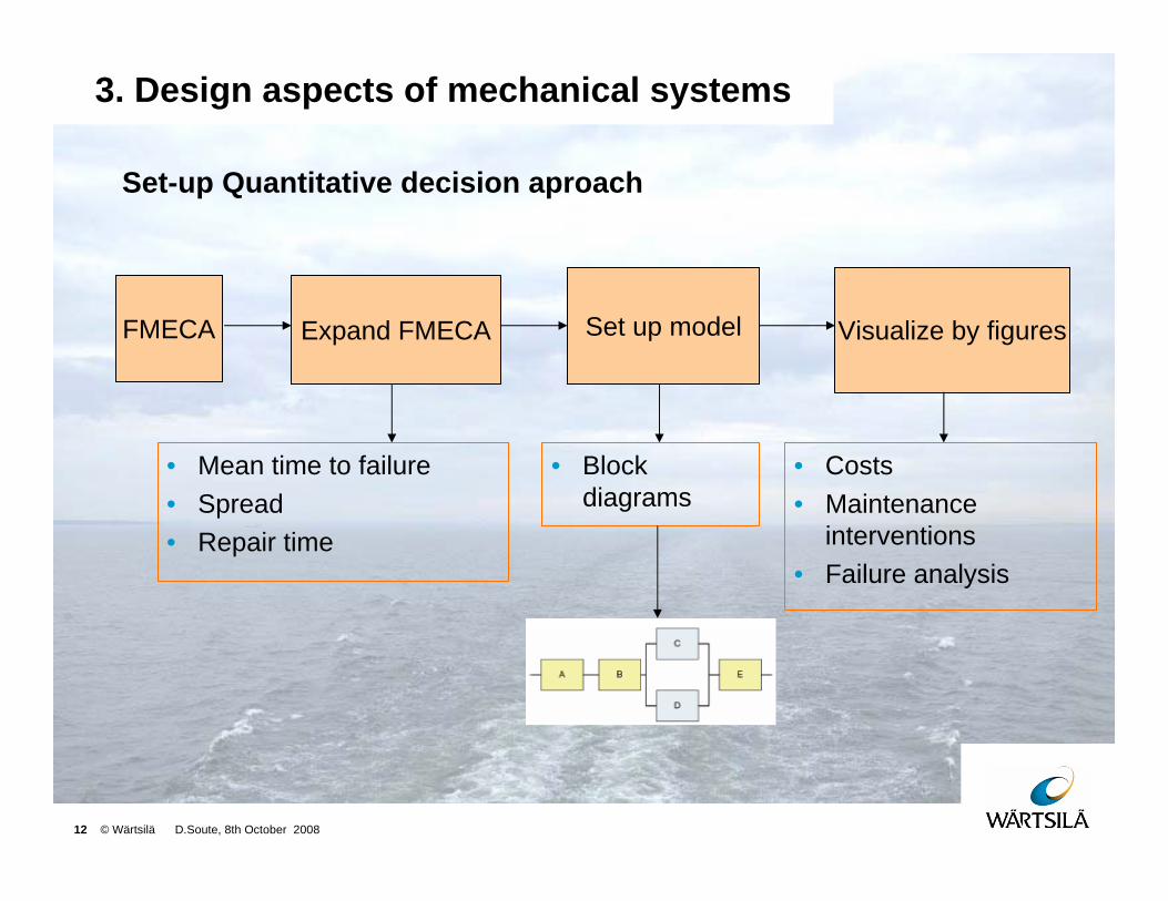
Set-up Quantitative decision aproach
FMECA Expand FMECA Set up model Visualize by figures
• Block diagrams
• Costs• Maintenance
interventions• Failure analysis
• Mean time to failure• Spread• Repair time

13 © Wärtsilä D.Soute, 8th October 2008
3. Design aspects of mechanical systems
Result FMECA
System/Assembly ScoreBearings 32Gearset PGB 16Propeller 16Shaft 16Steering gearbox 16
Transfer thrust in certain direction
360º / 4000 kW
Thruster STT (fixed pitch)
Steering
Degrees / min=2RPM
Hydraulic steering device
Transfer the power from motor to propeller
Able to absorb the maximum power
Shaft line
Converting rotation into thrust
Designed for 0 knots, 100% Thrust
Propeller
Level Module Failure Mode Local Effect System effect Probability Score Failure Cause
Saf. Env. Op.cap. Cost
B3 Propeller Broken blade No more thrustSystem has lost main function 1 2 2 16 16 16
Extreme external events
Severity
Score = Prob. x Sev.(highest)
Probability: 1,2,3,..5
Severity: 1,2,4,..16
14 © Wärtsilä D.Soute, 8th October 2008
3. Design aspects of mechanical systems
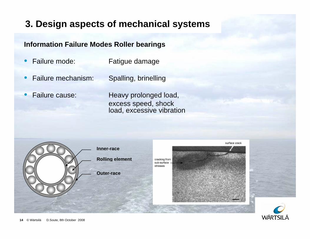
Information Failure Modes Roller bearings
• Failure mode: Fatigue damage
• Failure mechanism: Spalling, brinelling
• Failure cause: Heavy prolonged load, excess speed, shockload, excessive vibration
Inner-race
Rolling element
Outer-race

15 © Wärtsilä D.Soute, 8th October 2008
3. Design aspects of mechanical systems
Optimal design criteria:
• Pinion supported by roller bearings at both sides
• Separate axial and radial bearings
• Precise and stable tooth contact
pattern under variable loading (thrust)
• Teeth are finish-machined after
hardening
Propeller gearboxpinion
Crown wheel
16 © Wärtsilä D.Soute, 8th October 2008
3. Design aspects of mechanical systems
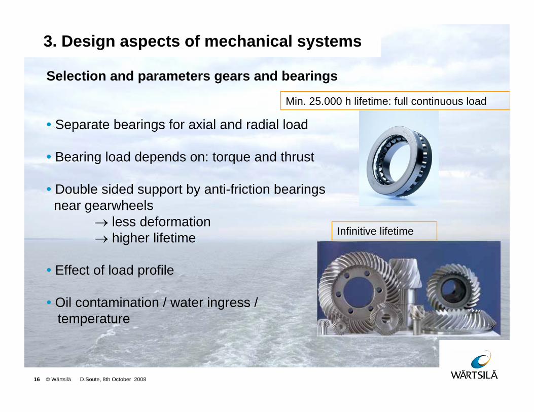
Selection and parameters gears and bearings
• Separate bearings for axial and radial load
• Bearing load depends on: torque and thrust
• Double sided support by anti-friction bearings near gearwheels
→ less deformation→ higher lifetime
• Effect of load profile
• Oil contamination / water ingress / temperature
Infinitive lifetime
Min. 25.000 h lifetime: full continuous load
17 © Wärtsilä D.Soute, 8th October 2008
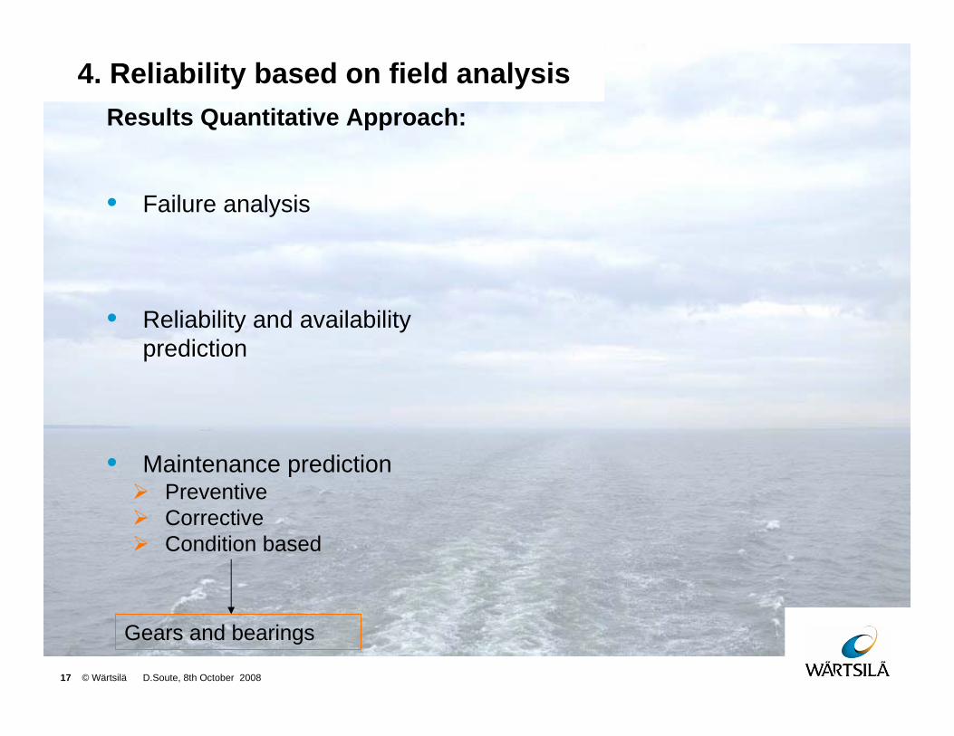
4. Reliability based on field analysisResults Quantitative Approach:
• Failure analysis
• Reliability and availability prediction
• Maintenance predictionPreventiveCorrectiveCondition based
Gears and bearings
18 © Wärtsilä D.Soute, 8th October 2008
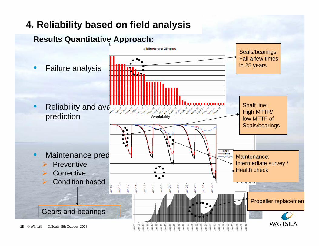
4. Reliability based on field analysisResults Quantitative Approach:
• Failure analysis
• Reliability and availability prediction
• Maintenance predictionPreventiveCorrectiveCondition based
Gears and bearings
Seals/bearings:Fail a few times in 25 years
Shaft line:High MTTR/ low MTTF of Seals/bearings
Maintenance:Intermediate survey / Health check
Propeller replacement
Availability
19 © Wärtsilä D.Soute, 8th October 2008
4. Reliability based on field analysis
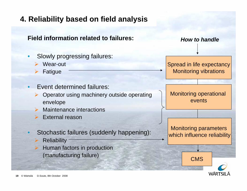
Field information related to failures:
• Slowly progressing failures:Wear-outFatigue
• Event determined failures:Operator using machinery outside operating envelopeMaintenance interactionsExternal reason
• Stochastic failures (suddenly happening):ReliabilityHuman factors in production (manufacturing failure)
Monitoring parameters which influence reliability
Monitoring operational events
Spread in life expectancyMonitoring vibrations
CMS
How to handle
20 © Wärtsilä D.Soute, 8th October 2008
4. Reliability based on field analysis
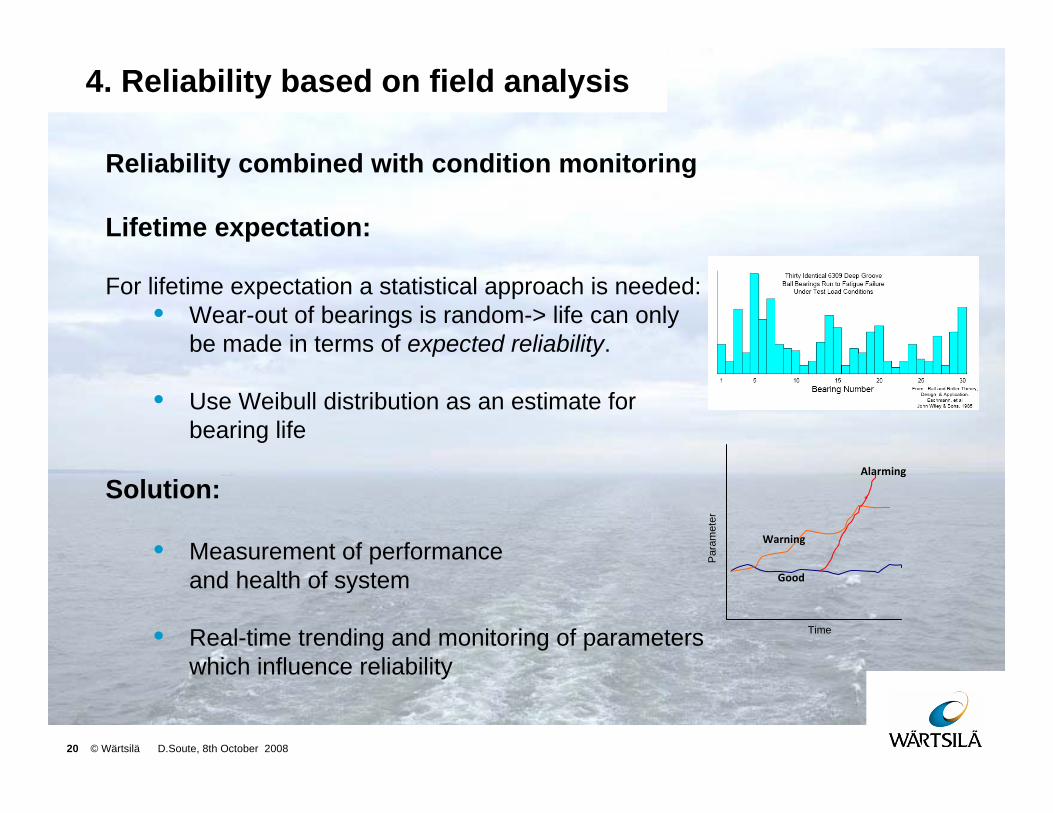
Reliability combined with condition monitoring
Lifetime expectation:
For lifetime expectation a statistical approach is needed:• Wear-out of bearings is random-> life can only
be made in terms of expected reliability.
• Use Weibull distribution as an estimate for bearing life
Solution:
• Measurement of performance and health of system
• Real-time trending and monitoring of parameters which influence reliability
Alarming
Warning
Good
Time
Par
amet
er
21 © Wärtsilä D.Soute, 8th October 2008
4. Reliability based on field analysis
80%
85%
90%
95%
100%
Time
Rel
iabi
lity
Nominal Reliability Corrected Reliability
RP
M
Axia
l loa
d
Oil
cont
amin
atio
n
Visc
osity
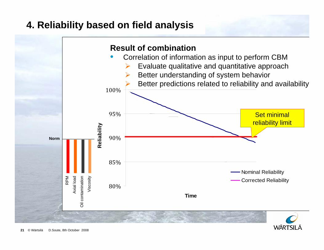
Set minimal reliability limit
Norm
Result of combination• Correlation of information as input to perform CBM
Evaluate qualitative and quantitative approachBetter understanding of system behaviorBetter predictions related to reliability and availability
22 © Wärtsilä D.Soute, 8th October 2008
5. Conclusions CMS, CBM
From Condition Monitoring to Condition Based Maintenance:
• Give a condition of components or system
• Minimize the possibility of the consequence of damage
• Possibility of adjusting maintenance intervals, depending on the results of CMS
• Better understanding of component / system behavior, this can be used for better predictions for reliability and availability
• Eventually this approach allows to perform condition based maintenance

23 © Wärtsilä D.Soute, 8th October 2008
6. End
Questions?
Top Related