


Languages
Pages
Legal


Database System
Database:
ü is a collection of related data.
ü represents some aspect of the
real world
ü is a logically coherent collection
of data with some inherent
meaning.
ü is designed, built, and populated
with data for a specific purpose.
Example: Amazon.com (over 2 terabytes - 200 different servers)
Source: (Elmasri and Navathe, 2011)
Database Management System (DBMS):
ü is a collection of programs that
enables users to create and
maintain a database.
ü system that facilitates the
processes of defining,
constructing, manipulating, and
sharing databases among
various users and applications.
Database System
Source: (Elmasri and Navathe, 2011)

An application program accesses
the database by sending queries or
requests for data to the DBMS.
Database System: Database + DBMS Software + Application
Programs.
Database System
Source: (Elmasri and Navathe, 2011)
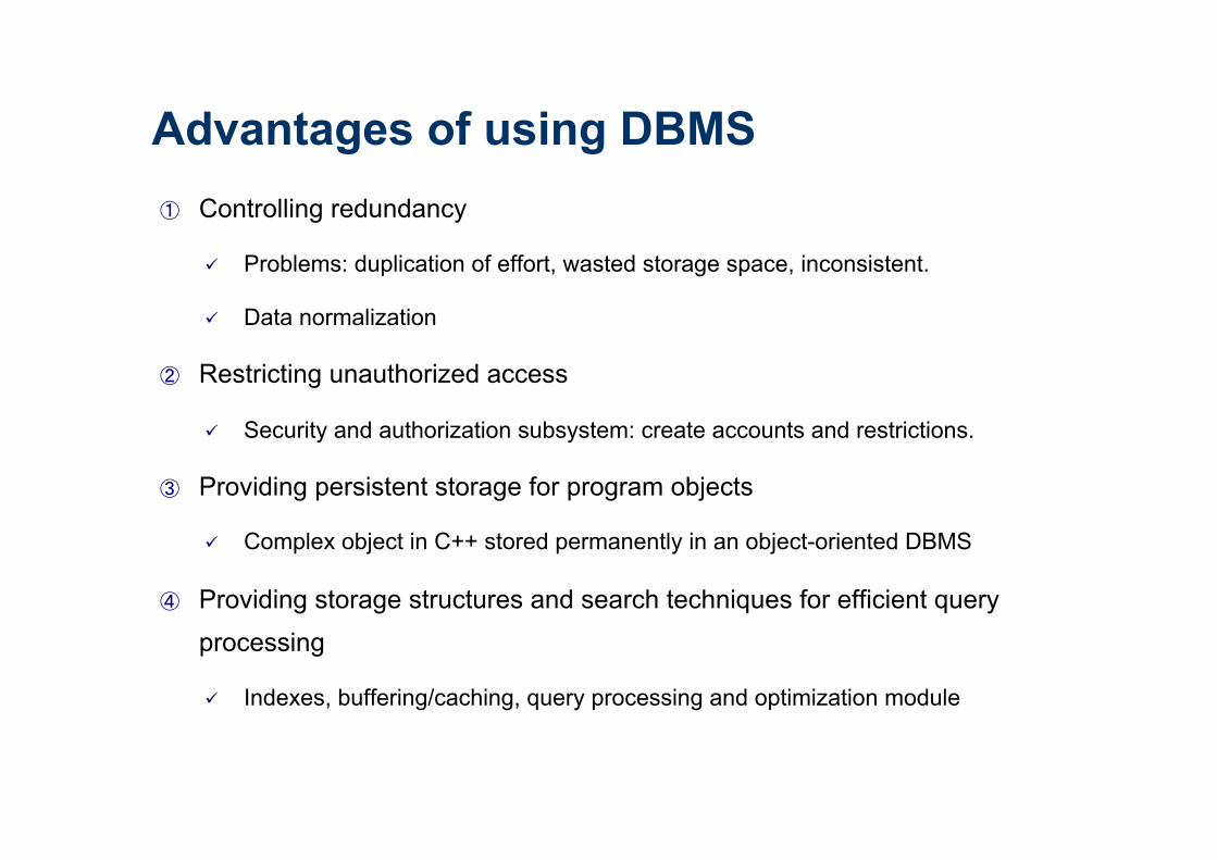
① Controlling redundancy
ü Problems: duplication of effort, wasted storage space, inconsistent.
ü Data normalization
② Restricting unauthorized access
ü Security and authorization subsystem: create accounts and restrictions.
③ Providing persistent storage for program objects
ü Complex object in C++ stored permanently in an object-oriented DBMS
④ Providing storage structures and search techniques for efficient query processing
ü Indexes, buffering/caching, query processing and optimization module
Advantages of using DBMS

⑤ Providing backup and recovery
ü Recovery subsystem: ensure that the transaction is resumed from the point at
which it was interrupted so that its full effect is recorded in the database.
⑥ Providing multiple user interfaces
ü Query languages, programming language interfaces, Graphical User Interfaces
(GUIs), web GUI interfaces, etc.
Advantages of using DBMS

DBMS: Multiple User Interfaces
Database
DBMS
Prompt
int main() { … }
C++ API
GUI

⑦ Representing complex relationships among data
ü Represent a variety of complex relationships among the data, define new
relationships, and retrieve and update related data easily and efficiently.
⑧ Enforcing integrity constraints
ü Integrity constraints: referential integrity, key or uniqueness, semantics, …
⑨ Permitting inference and actions using rules
ü Deductive database systems: define deduction rules for inferencing new
information from the stored database facts.
ü Triggers, stored procedures, …
Advantages of using DBMS
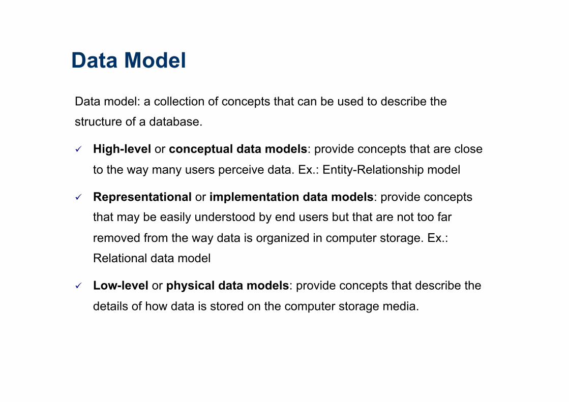
Data model: a collection of concepts that can be used to describe the
structure of a database.
ü High-level or conceptual data models: provide concepts that are close
to the way many users perceive data. Ex.: Entity-Relationship model
ü Representational or implementation data models: provide concepts that may be easily understood by end users but that are not too far
removed from the way data is organized in computer storage. Ex.:
Relational data model
ü Low-level or physical data models: provide concepts that describe the
details of how data is stored on the computer storage media.
Data Model

Database Design Source: (Elmasri and Navathe, 2011)
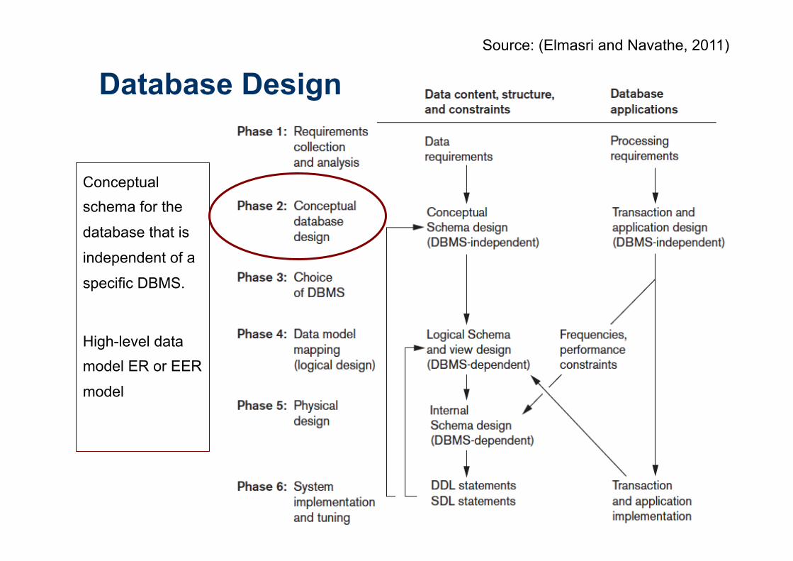
Conceptual schema for the
database that is
independent of a
specific DBMS.
High-level data model ER or EER
model
Database Design Source: (Elmasri and Navathe, 2011)

Entity-Relationship – ER Model
ü Proposed in 1976 by Peter Chen
ü Conceptual data models use concepts such as entities, attributes, and relationships:
ü Entity: real-world object or concept from the miniworld that is described in the database.
ü Attribute: property of interest that further describes an entity.
ü Relationship: association among the entities.
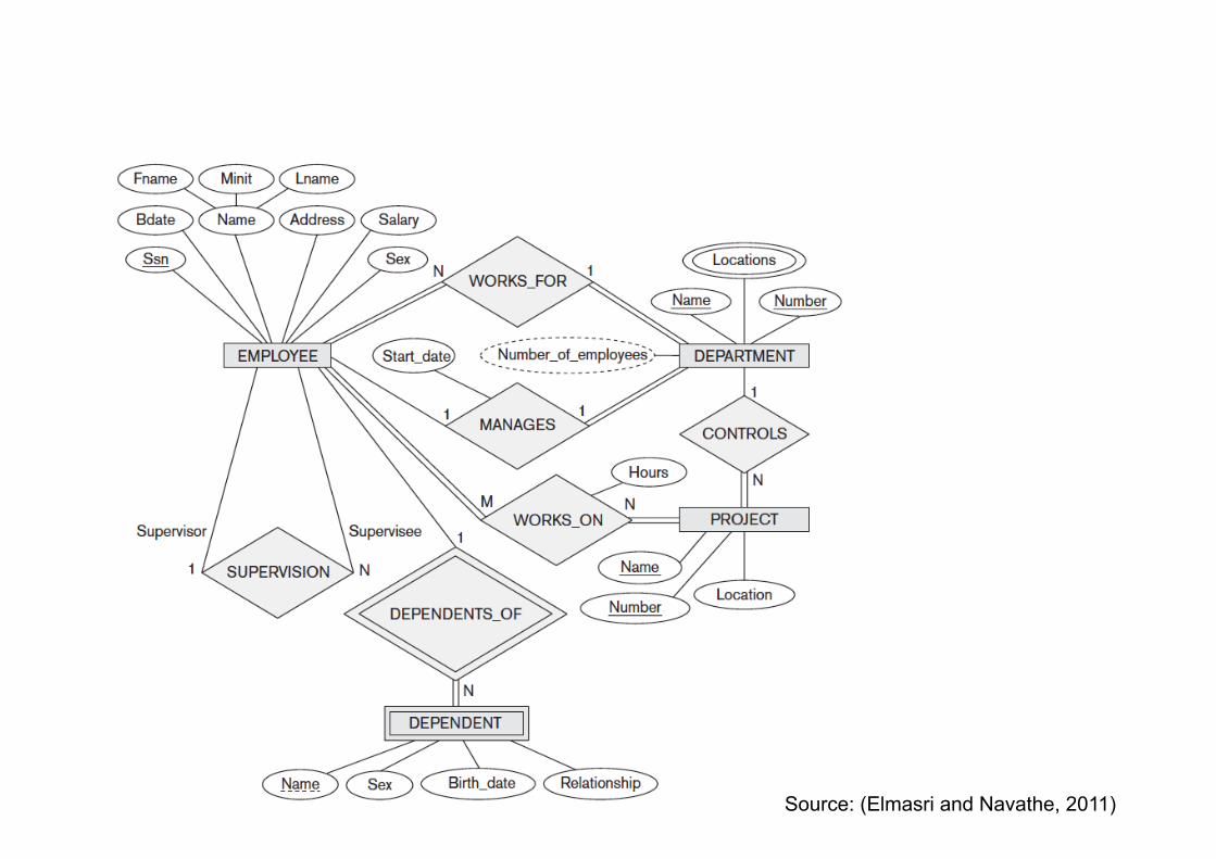
Source: (Elmasri and Navathe, 2011)

Source: (Elmasri and Navathe, 2011)
Entities:
EMPLOYEE,
DEPARTAMENT,
PROJECT,
DEPENDENT
Relationships:
WORKS_FOR,
MANAGES,
CONTROLS,
WORKS_ON,
DEPENDENT_OF,
SUPERVISION
Attributes
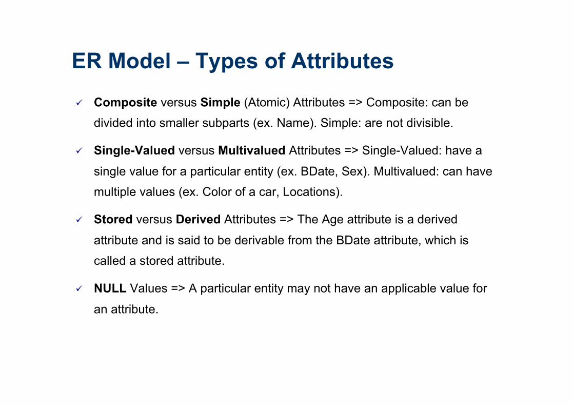
ü Composite versus Simple (Atomic) Attributes => Composite: can be
divided into smaller subparts (ex. Name). Simple: are not divisible.
ü Single-Valued versus Multivalued Attributes => Single-Valued: have a
single value for a particular entity (ex. BDate, Sex). Multivalued: can have
multiple values (ex. Color of a car, Locations).
ü Stored versus Derived Attributes => The Age attribute is a derived
attribute and is said to be derivable from the BDate attribute, which is
called a stored attribute.
ü NULL Values => A particular entity may not have an applicable value for
an attribute.
ER Model – Types of Attributes

ER Model – Key Attributes
Key Attributes
Multivalued Attribute
Source: (Elmasri and Navathe, 2011)
Composite Attribute
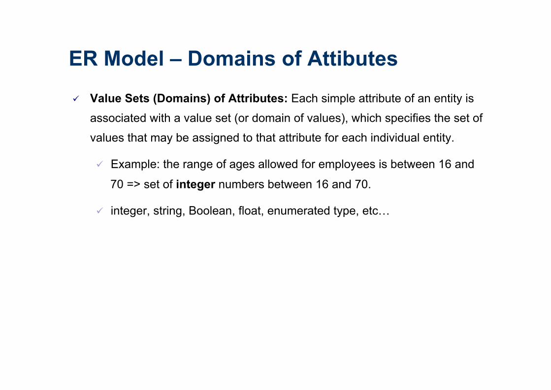
ER Model – Domains of Attibutes
ü Value Sets (Domains) of Attributes: Each simple attribute of an entity is
associated with a value set (or domain of values), which specifies the set of
values that may be assigned to that attribute for each individual entity.
ü Example: the range of ages allowed for employees is between 16 and
70 => set of integer numbers between 16 and 70.
ü integer, string, Boolean, float, enumerated type, etc…

ER Model – Relationships
ü Degree: number of participating entities. Binary: between two entities,
ternary: among three entities, and so on.
ü Recursive relationships: between two instances of the same entity. Ex.
SUPERVISION
ü Cardinality ratios for binary relationships: 1:1, 1:N, N:1, and M:N.
ü Ex: MANAGES (1:1), WORKS_FOR (1:N), WORKS_ON (M:N)
ü Attributes: relationship can also have attributes, similar to those of entities.

ER Model – Cardinality
1:1
Source: (Elmasri and Navathe, 2011)
N:N

ER Model – Relationships
ü Participation Constraints and Existence Dependencies:
ü Total participation: every entity in the total set of employee entities must be related to a department entity via WORKS_FOR. Total
participation is also called existence dependency.
ü Partial participation: some or part of the set of employee entities are related to some department entity via MANAGES, but not necessarily
all.
In ER diagrams, total participation (or existence dependency) is displayed
as a double line connecting the participating entity type to the relationship,
whereas partial participation is represented by a single line.

Source: (Elmasri and Navathe, 2011)
Total participation
Partial participation

ER Model – Weak Entity
ü Weak entity: entity that do not have key attributes of their own. A weak
entity type always has a total participation constraint (existence
dependency) with respect to its identifying relationship because a weak
entity cannot be identified without an owner entity. A weak entity type
normally has a partial key, which is the attribute that can uniquely identify
weak entities that are related to the same owner entity. Ex. DEPENDENT
ü Strong entity: regular entity that do have a key attribute.
In ER diagrams, both a weak entity type and its identifying relationship are
distinguished by surrounding their boxes and diamonds with double lines.
The partial key attribute is underlined with a dashed or dotted line.

Source: (Elmasri and Navathe, 2011)
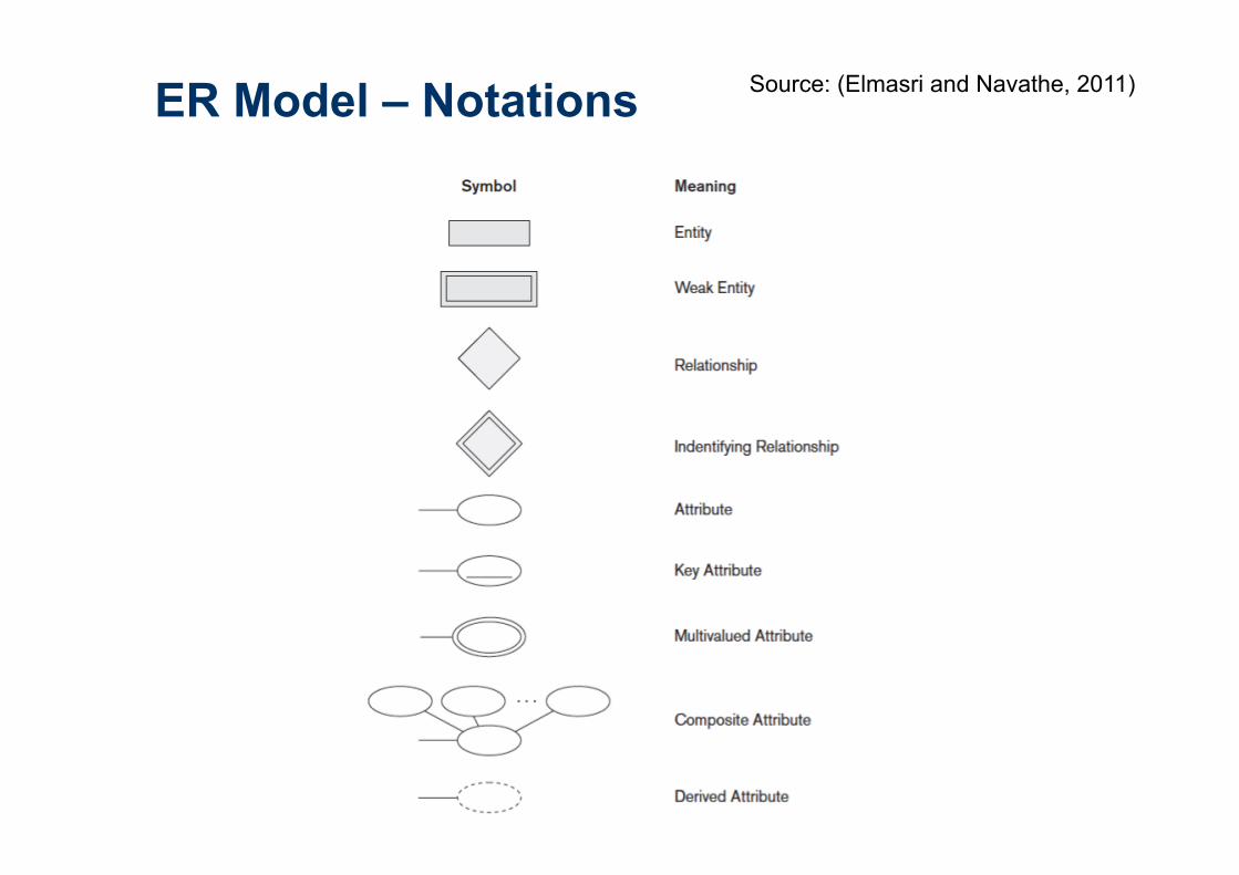
ER Model – Notations Source: (Elmasri and Navathe, 2011)
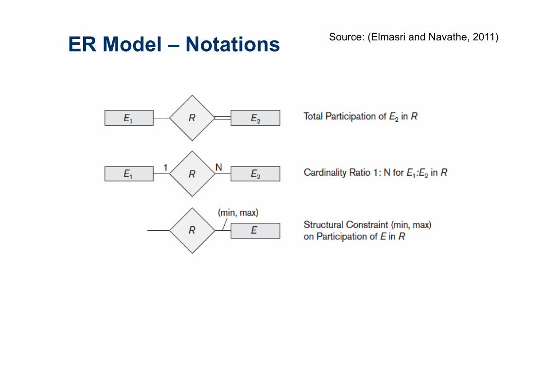
ER Model – Notations Source: (Elmasri and Navathe, 2011)
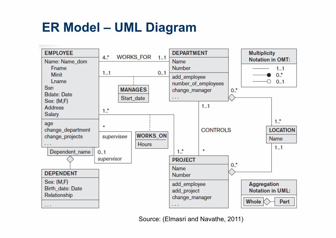
ER Model – UML Diagram
Source: (Elmasri and Navathe, 2011)

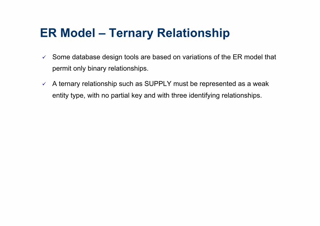
ER Model – Ternary Relationship
Source: (Elmasri and Navathe, 2011)
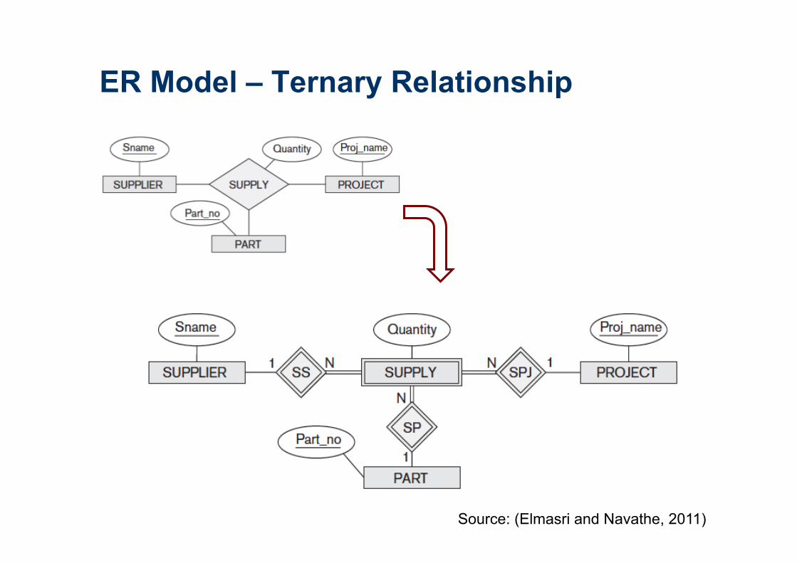
ER Model – Ternary Relationship
ü Some database design tools are based on variations of the ER model that
permit only binary relationships.
ü A ternary relationship such as SUPPLY must be represented as a weak
entity type, with no partial key and with three identifying relationships.
ER Model – Ternary Relationship
Source: (Elmasri and Navathe, 2011)

Lista 02 – Exercício 01

The conceptual schema from the
high-level data
model used in
Phase 2 is
mapped into the
data model of the
chosen DBMS.
Database Design Source: (Elmasri and Navathe, 2011)

The Relational Data Model
n First introduced by Ted Codd of IBM Research in 1970 in a classic paper
n Early 1980s: first commercial implementations, such as the Oracle DBMS.
n Current popular relational DBMSs (RDBMSs) include:
¨ Commercial: DB2 and Informix Dynamic Server (from IBM), Oracle
(from Oracle), Sybase DBMS (from Sybase) and SQLServer and
Access (from Microsoft).
¨ Open source: MySQL and PostgreSQL
DB2. Universal Database
33
Relational DBMS - RDBMS

n Represents the database as a collection of relations (table of values)
n Formal terminology: row => tuple, a column header => attribute, table =>
relation, data type describing the types of values that can appear in each
column => domain of possible values.
The Relational Data Model
Source: (Elmasri and Navathe, 2011)

Relation - Definition
Given the domains D1, D2, ..., Dn that are not necessarily distinct, a relation is
defined as:
R = { (d1, d2,..., dn) | d1 ∈ D1, d2 ∈ D2,..., dn ∈ Dn }
ü A set (d1, d2,..., dn) of ordered values define a tupla
ü A relation is a set of ordered n-tuplas, where n define the relation degree

Relation - Schema x Instances
Source: (Elmasri and Navathe, 2011)
Instances
Schema

Relation – Characteristics
ü Ordering of Tuples in a Relation: tuples in a relation do not have any
particular order.
ü Ordering of Values within a Tuple: according to the definition of a
relation, an n-tuple is an ordered list of n values, so the ordering of values
in a tuple is important.
ü Values and NULLs in the Tuples: each value in a tuple is an atomic value
(not divisible). NULL values: values of attributes that may be unknown or
may not apply to a tuple.
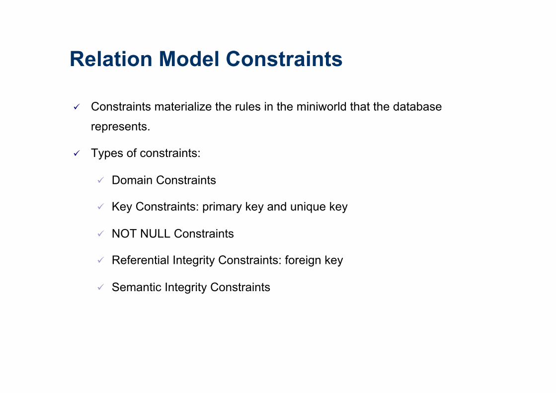
Relation Model Constraints
ü Constraints materialize the rules in the miniworld that the database
represents.
ü Types of constraints:
ü Domain Constraints
ü Key Constraints: primary key and unique key
ü NOT NULL Constraints
ü Referential Integrity Constraints: foreign key
ü Semantic Integrity Constraints

Domain Constraints
n The data types associated with domains typically include:
¨ Standard numeric data types for integers (such as short integer, integer, and long integer);
¨ Real numbers (float and double precision, float);
¨ Characters;
¨ Booleans;
¨ Fixed-length strings and variable-length strings;
¨ Date, time, timestamp, and money
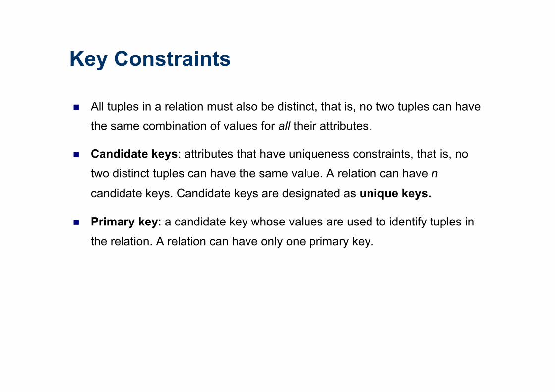
Key Constraints
n All tuples in a relation must also be distinct, that is, no two tuples can have
the same combination of values for all their attributes.
n Candidate keys: attributes that have uniqueness constraints, that is, no
two distinct tuples can have the same value. A relation can have n
candidate keys. Candidate keys are designated as unique keys.
n Primary key: a candidate key whose values are used to identify tuples in
the relation. A relation can have only one primary key.
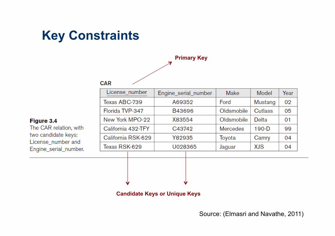
Key Constraints
Candidate Keys or Unique Keys
Primary Key
Source: (Elmasri and Navathe, 2011)

Referential Integrity Constraint
n It is specified between two relations and is used to maintain the
consistency among tuples in the two relations.
n Foreign key: specify a referential integrity constraint between the two
relation schemas R1 and R2.
¨ The attributes in FK have the same domain(s) as the primary key attributes PK of R2; the attributes FK are said to reference or refer to
the relation R2.
¨ A value of FK in a tuple t1 of the current state r1(R1) either occurs as a value of PK for some tuple t2 in the current state r2(R2) or is NULL.

Source: (Elmasri and
Navathe, 2011)
Primary Keys ?
Unique Keys ?
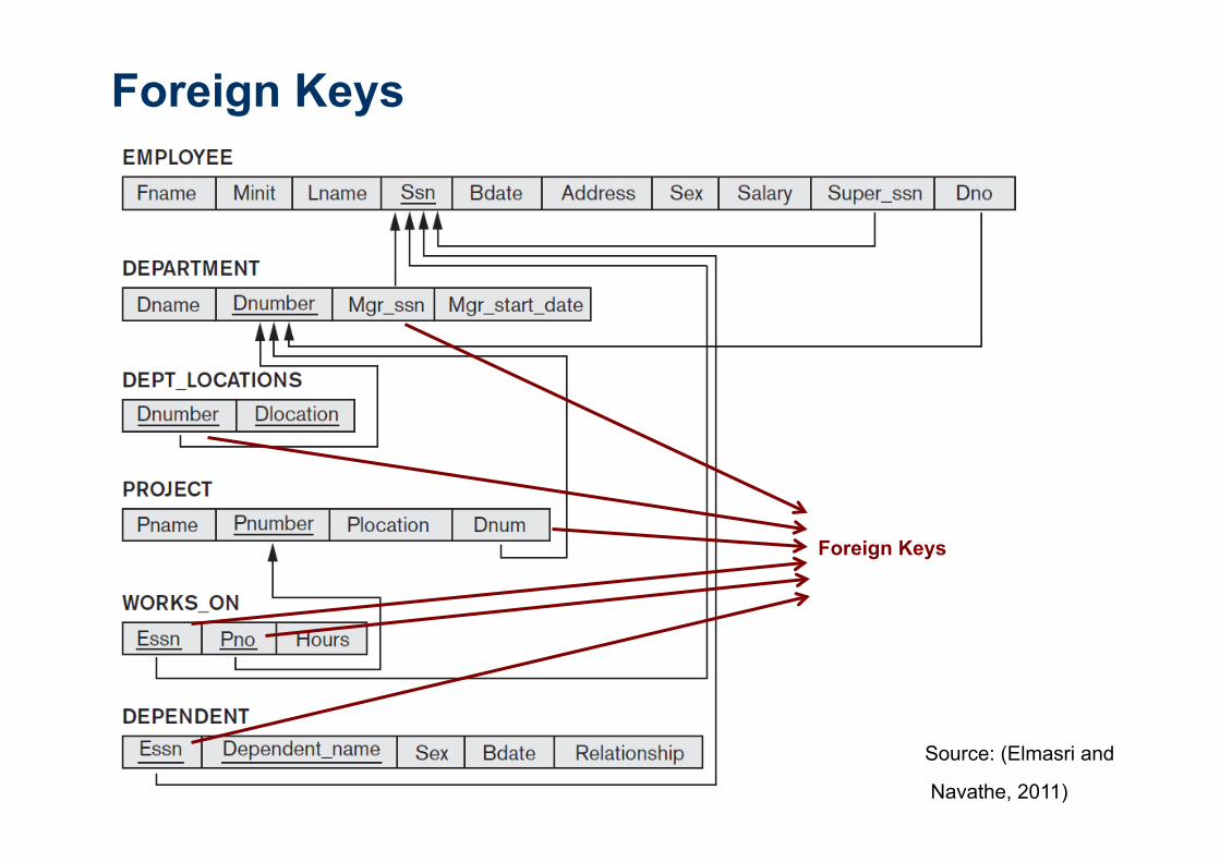
Foreign Keys ?
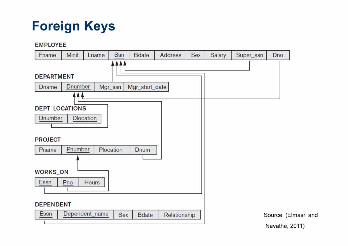
Foreign Keys
Source: (Elmasri and
Navathe, 2011)
Foreign Keys
Foreign Keys
Source: (Elmasri and
Navathe, 2011)

Semantic Integrity Constraints
n Example: “the salary of an employee should not exceed the salary of the
employee’s supervisor and the maximum number of hours an employee
can work on all projects per week is 56”
n Such constraints can be specified and enforced within the application
programs that update the database, or by using a general-purpose
constraint specification language.
n Examples: triggers and assertions. In SQL: CREATE ASSERTION and
CREATE TRIGGER

Relational Model – Operations
n Insert: provides a list of attribute values for a new tuple t that is to be
inserted into a relation R.
¨ Example: Insert <‘Cecilia’, ‘F’, ‘Kolonsky’, NULL, ‘1960-04-05’, ‘6357
Windy Lane, Katy,TX’, F, 28000, NULL, 4> into EMPLOYEE.
¨ Result: This insertion violates the entity integrity constraint (NULL for
the primary key Ssn), so it is rejected.

Relational Model – Operations
n Delete: remove tuples of a relation.
ü Example: Delete the EMPLOYEE tuple with Ssn = ‘999887777’.
ü Result: This deletion is not acceptable, because there are tuples in
WORKS_ON that refer to this tuple. Hence, if the tuple in EMPLOYEE is
deleted, referential integrity violations will result.

Relational Model – Operations
n Update (or Modify): change the values of one or more attributes in a tuple
(or tuples) of some relation R.
ü Example: Update the Dno of the EMPLOYEE tuple with Ssn =
‘999887777’ to 7.
ü Result: Unacceptable, because it violates referential integrity.

Transaction
n A transaction is an executing program that forms a logical unit of database
processing.
n It includes one or more database access operations—these can include
insertion, deletion, modification, or retrieval operations.
n End of the transaction: database in a valid or consistent state
n Transactions submitted by various users may execute concurrently and may access and update the same database items.
n Concurrency control and recovery mechanisms are necessary

Problems of concurrent execution
Source: (Elmasri and Navathe, 2011)
Two transactions: T1 and T2

Problems of concurrent execution
Source: (Elmasri and Navathe, 2011)
Two transactions: T1 and T2
Transaction
n A transaction is an atomic unit of work that should either be completed in its
entirety or not done at all.
n For recovery purposes, the system needs to keep track of when each
transaction starts, terminates, and commits or aborts:
¨ BEGIN_TRANSACTION
¨ END_TRANSACTION
¨ COMMIT_TRANSACTION
¨ ROLLBACK (or ABORT)
Transaction – ACID properties
n Atomicity: A transaction is an atomic unit of processing; it should either be
performed in its entirety or not performed at all.
n Consistency preservation: if an transaction is completely executed from
beginning to end without interference from other transactions, it should take
the database from one consistent state to another.
n Isolation: The execution of a transaction should not be interfered with by
any other transactions executing concurrently
n Durability or permanency. The changes applied to the database by a
committed transaction must persist in the database. These changes must
not be lost because of any failure.

Transaction – Serial Schedule
Source: (Elmasri and Navathe, 2011)
Serial schedules involving transactions T1 and T2. (a) Serial schedule A: T1
followed by T2. (b) Serial schedule B: T2 followed by T1.
Transaction – Nonserial Schedule
Source: (Elmasri and Navathe, 2011)
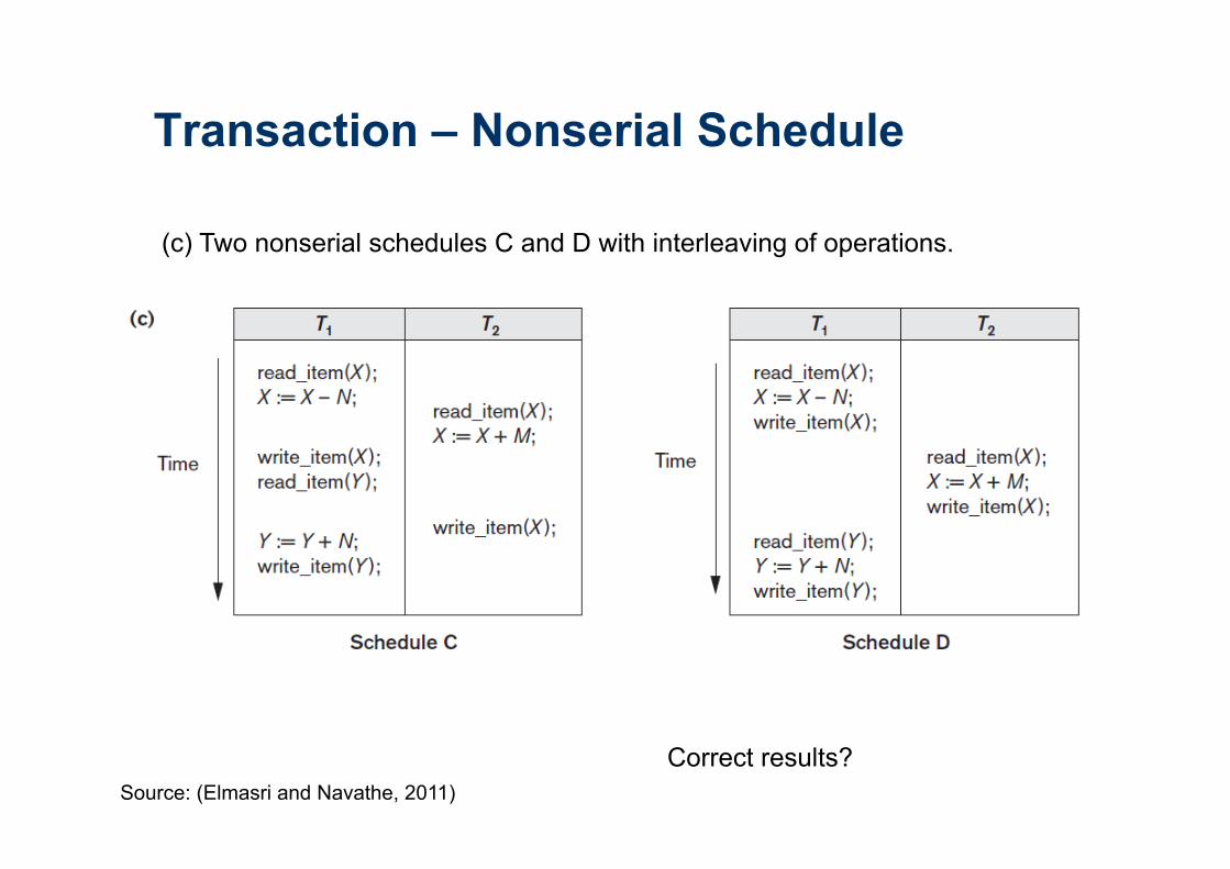
(c) Two nonserial schedules C and D with interleaving of operations.
Correct results?
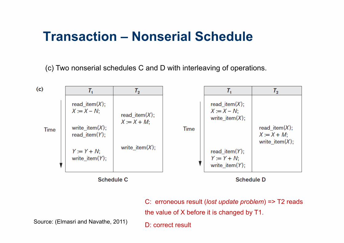
Transaction – Nonserial Schedule
Source: (Elmasri and Navathe, 2011)
(c) Two nonserial schedules C and D with interleaving of operations.
C: erroneous result (lost update problem) => T2 reads the value of X before it is changed by T1.
D: correct result

n A standard (ISO) for relational databases.
n Based on the relational algebra
n Higher-level declarative language interface: user only specifies what the
result is to be, leaving the actual optimization and decisions on how to
execute the query to the DBMS.
n Statements for:
ü data definitions, queries, and updates: DDL and DML
ü defining views on the database
ü specifying security and authorization
ü defining integrity constraints, and
ü specifying transaction controls.
SQL: Structured Query Language
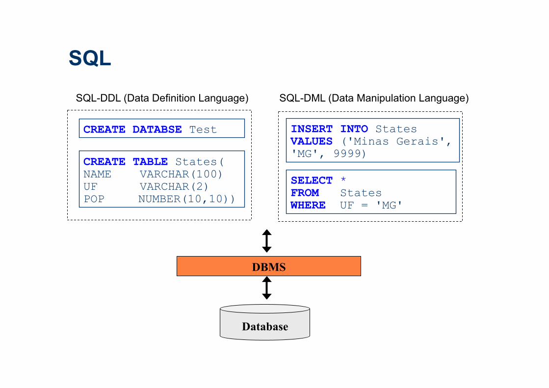
CREATE TABLE States( NAME VARCHAR(100) UF VARCHAR(2) POP NUMBER(10,10))
Database
DBMS
CREATE DATABSE Test
SELECT * FROM States WHERE UF = 'MG'
INSERT INTO States VALUES ('Minas Gerais', 'MG', 9999)
SQL-DDL (Data Definition Language) SQL-DML (Data Manipulation Language)
SQL
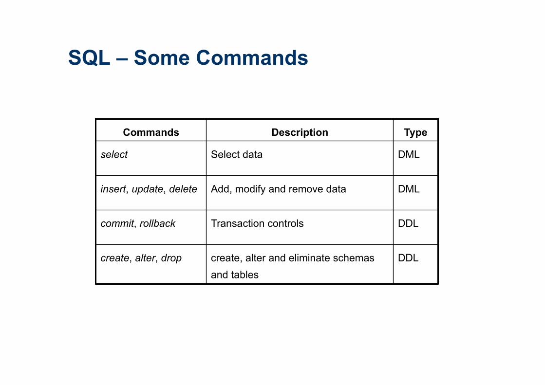
Commands Description Type
select Select data DML
insert, update, delete Add, modify and remove data DML
commit, rollback Transaction controls DDL
create, alter, drop create, alter and eliminate schemas and tables
DDL
SQL – Some Commands
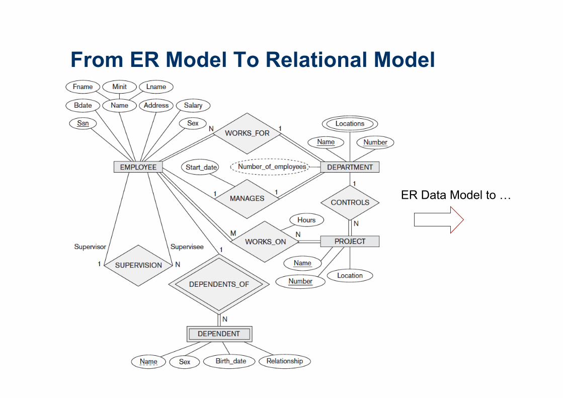
From ER Model To Relational Model
ER Data Model to …

From ER Model To Relational Model
Relational
Model

ER Model To Relational Model
Step 1: Mapping of Regular Entity Types. For each regular entity E, create a
relation R that includes all the simple attributes of E.
Example: EMPLYOEE, DEPARTAMENT, PROJECT
Step 2: Mapping of Weak Entity Types. For each weak entity W with owner
entity E, create a relation R and include all simple attributes of W as attributes
of R. In addition, include as foreign key attributes of R, the primary key
attribute(s) of E.
Example: DEPENDENT

ER Model To Relational Model
Step 3: Mapping of Binary 1:1 Relationship Types: identify the relations S
and T that correspond to the relationship and choose one approach:
(1) Foreign key approach: Choose one of the relations, for example S, and
include as a foreign key in S the primary key of T.
(2) Merged relation approach: Merge the two entities into a single relation.
(3) Cross-reference or relationship relation approach: set up a third relation
R for the purpose of cross-referencing the primary keys of the two relations S
and T representing the entities.
ER Model To Relational Model
Example: (Approach 1): include the primary key of the EMPLOYEE as foreign
key in the DEPARTMENT (Mgr_ssn). Also include the simple attribute
Start_date of the MANAGES relationship (Mgr_start_date).
ER Model To Relational Model
Step 4: Mapping of Binary 1:N Relationship Types: identify the relation S
that represents the participating entity at the N-side of the relationship. Include
as foreign key in S the primary key of the relation T.
Examples:
1. WORKS_FOR => primary key Dnumber of the DEPARTMENT as foreign
key in the EMPLOYEE (Dno).
2. SUPERVISION => primary key of the EMPLOYEE as foreign key in the
EMPLOYEE (Super_ssn).
3. CONTROLS => foreign key attribute Dnum of PROJECT, which references
the primary key Dnumber of the DEPARTMENT.

ER Model To Relational Model
Step 5: Mapping of Binary M:N Relationship Types: For each binary M:N
relationship type R, create a new relation S to represent R. Include as foreign
key attributes in S the primary keys of the relations that represent the
participating entity types; their combination will form the primary key of S. Also
include any simple attributes of the M:N relationship as attributes of S.
Example: relationship WORKS_ON => relation WORKS_ON
ER Model To Relational Model
Step 6: Mapping of Multivalued Attributes: For each multivalued attribute A,
create a new relation R that include an attribute corresponding to A, plus the
primary key attribute K — as a foreign key in R — of the relation that
represents the entity type or relationship type that has A as a multivalued
attribute.
Example: create a relation DEPT_LOCATIONS. The attribute Dlocation
represents the multivalued attribute LOCATIONS of DEPARTMENT, while
Dnumber—as foreign key—represents the primary key of the DEPARTMENT
relation.
ER Model To Relational Model
Step 7: Mapping of N-ary Relationship Types. For each n-ary relationship
type R, where n > 2, create a new relation S to represent R. Include as foreign
key attributes in S the primary keys of the relations that represent the
participating entity types. Also include any simple attributes of the n-ary
relationship type as attributes of S.

ER Model To Relational - Summary
Source: (Elmasri and Navathe, 2011)

Lista 02 - Exercício 02

Specifications
for the stored
database in terms
of physical file
storage structures,
buffer, and indexes.
Database Design Source: (Elmasri and Navathe, 2011)
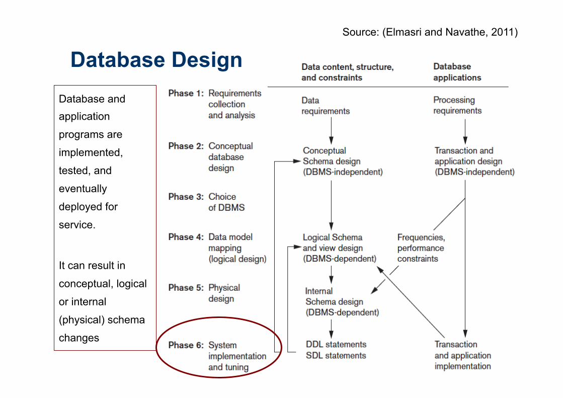
Database and application
programs are
implemented,
tested, and
eventually
deployed for
service.
It can result in
conceptual, logical
or internal
(physical) schema
changes
Database Design Source: (Elmasri and Navathe, 2011)
Top Related