


Languages
Pages
Legal

.1_1-
BC MINISTRY OF TRANSPORTATION AND INFRASTRUCTURE
Queens Bay Ferry Terminal Concept Study
09473 - OO-MA-REP-0002
22 June 2012
WorleyParsons Canada Suite SOO, 4321 Still Creek Drive Burnaby, Be V5C 6S7 CANADA Phone: . , 604 298 1616 Facsimile: +1 604 298 1625 www.woneyparsons.com
C Copyright 2012 VOIor1eyParsons
EcoNomics
TRA-2014-00242 Page 1
Be MINISTRY OF TRANSPORTATION AND INFRASTRUCTURE
QUEENS BAY FERRY TERMINAL
CONCEPT STUDY
PROJECT 09473· QUEENS BAY FERRY TER NAL
DESCRIPTION
o Issued for Use
094 73-OO-MA·REP.ooo2.R8IIO.doc Document No. QO.MA·REP.()()(J2
ORIG WORLEY· PAASONS APPROVAL
om CLIENT APPROVAL
DATe
Page i
EcoNomics
TRA-2014-00242 Page 2
BC MINISTRY OF TRANSPORTATION AND INFRASTRUCTURE
QUEENS BAY FERRY TERMINAL
CONCEPT STUDY
Disclaimer
This Document is conceptual in nature and represents the work of WorleyParsons Canada
SeNices Ltd. performed to recognized engineering principles and practices appropriate for conceptual engineering work and the terms of reference provided by the WorleyParsons Canada Services Ltd. contractual Customer, BC Ministry of Transportation and Infrasimcture (the ·Customer"). This Document may not be relied upon for detailed implementation or any other purpose not specifically identified within this Document. This Document is confidential and
prepared solely for the use of the Customer. The contents of this Document may not be relied upon by any party other than the Customer, and neither WorleyParsons Canada Services Ltd., its subconsultants nor their respective employees assume any liability for any reason, including, but not limited to, negligence, to any other party for any information or representation herein. The extent of any warranty or guarantee of l!"lis Document or the information contained therein in favour of the Customer is limited to the warranty or guarantee, if any, contained in the contract
between the Customer and WorleyParsons Canada Services Ltd.
Page iii 09473 : Rev 0 : 22 June 2012
EcoNomics
TRA-2014-00242 Page 3
BC MINISTRY OF TRANSPORTATION AND INFRASTRUCTURE
QUEENS BAY FERRY TERMINAL
CONCEPT STUDY
CONTENTS
1.
2.
2.1
2.2
2.3
2.4
3.
3.1
3.2
3.3
3.4
4.
5.
5.1
5.2
6.
6.1
6.2
6.3
6.4
6.5
6.6
6.7
7.
8.
INTRODUCTION
BALFOUR FERRY TERMINAL
Background ,.
Upland Structures
Marine Structures ...... .. .. ... ..
Balfour Terminal Operational and Risk Concerns .....
QUEENS BAY SITES ............. .... . .
Queens Bay ............. ..
. ............. 1
. ............... ....... 2
. ... ........ .. 2
....... 2
... ....... . 2
.................... 3
. .............................. .. 5
. .......... .. ............... .. .. 5
Queens Bay South ............... ...... .. ................. 5
Queens Bay North .. .............................. ............................. .............. . ..................... 6
Site Selection Summary .............. . .............. ..... ... ..... .......... .. . ...... 6
ROAD ACCESS ................... . .. .... . 7
TERMINAL COMPOUND .. .............. . . .............. 8
Terminal Compound ...... ...................... . . .............. .. .......... ............ .......... 8
Buildings ..... .
MARINE STRUCTURES ...... .
Site Conditions ................ .. .................. .
Berth Layout... .......... .
Wingwalls ....... ......................... . ........ ... ........... .......... ..... .
Pontoon ...
Dolphins
Ramp and Pontoon Relocation
Project Completion and Balfour Decommissioning.
CONCEPTUAL COST ESTIMATE .
SUMMARy ............... ... .
. ........... ....... ...... 8
. ..... ... .... .... .. 9
. ... 9
. ... . 9
. .... ..... ... ....... .... 10
..10
............ 10
........... 11
.. ....... 11
.. ................ 12
. ....... ............ 15
09473 : Rev 0 : 22 June 2012 Page v
EcoNomics TRA-2014-00242 Page 4
Worley Parsons resources & energy
Tables within Text
TABLE A CONCEPTUAL COST ESTIMATE ............ ............. ......... ........ ....... .................... 12
Appendices
APPENDIX 1 SKETCH
Page vi 0!l473.-00.MA.REP-0002_RevO.doc
EcoNomics TRA-2014-00242 Page 5
1. INTRODUCTION
BC MINISTRY OF TRANSPORTATION AND INFRASTRUCTURE
QUEENS BAY FERRY TERMINAL
CONCEPT STUDY
The BC Ministry of Transportation and Infrastructure (MTI) provides a vehicle and passenger ferry service on Kootenay Lake for free public travel between Balfour Ferry Tenninal and Kootenay Bay. The ferry service is provided by two vessels operated by Western Pacific Marine under a services contract with MTI. The newer and larger vessel, Osprey, operates year round. The M.V. Balfour operates during the peak
summer travel season and in relief during maintenance of the Osprey. It is our understanding that the duration for loading a vessel, the lake crossing, and unloading is 50 minutes and a round trip is one hour and 40 minutes.
The existing Balfour Ferry Terminal is located along the north shore between the junction of Kootenay Lake and the West Arm of Kootenay Lake and has direct access to Highway 3A for travellers destined west to Nelson, or to Highway 31 for travellers headed north towards Kaslo. Kootenay Bay is on the east shore of Kootenay Lake and provides a connection to Highway 3A used by travellers headed south towards Creston. Kootenay Bay is mentioned to provide context for this concept study but is not a subject
of this report.
The purpose of this concept study is to consider a potential relocation of the terminal on the west side of
Kootenay Lake from Balfour to Queens Bay.
09473 . Rev O 22 June 2012 P1.'Ie 1
EcoNomiCS TRA-2014-00242 Page 6
R e!!J Worley Parsons resources & energy
2. BALFOUR FERRY TERMINAL
2.1 Background
The use of the Balfour site as a marine terminal predates the initiation of Kootenay Lake selVice by the
Province in 1947. It is assumed that the site was selected by pioneers due to the good terrain , sheltered location, and access to a roadway for westward travel.
During the 19905, options for relocating either or both of Balfour Terminal and Kootenay Bay Terminal
were extensively studied by the Ministry of Transportation and Highways. It was decided to upgrade the
existing facilities for service by the new vessel, Osprey, which replaced the M.V. Anscomb. The terminal upgrades were completed in 2000.
2.2 Upland Structures
The Balfour Ferry Terminal has direct access from Highway 3A. There is a paved vehicle staging
compound located between the highway and the start of the access Irestle. There is an entry lane, an exit lane and six parking lanes to provide space for approximately 110 vehicles with some additional overflow
capacity.
The terminal includes a storage shed at the northeast comer of the trestle, a public washroom, a grassy
area, and a visitor information centre.
Staff parking is provided in a fenced enclosure near the highway.
The site has adjacent amenities, but they are not actually on the terminal property.
2.3 Marine Structures
The existing Balfour Ferry Terminal has an operating berth and a layover berth, and typical marine
structures common to a ferry terminal.
A treated timber approach trestle provides vehicle access to the vessel from the shore. The trestle has 11
timber pile bents supporting pile caps, stringers, ties, and decking. The topside includes timber bullrails
and handrails. The trestle received significant repairs and replacement of a number of timber
superstructure elements in the spring of 2012.
At the offshore end of the timber trestle there is a ramp support abutment which consists of a reinforced
concrete pile cap supported by steel H-piles. The ramp abutment also supports the last span of the timber
trestle. The inshore end of the ramp is supported with hinged bearings that allow vertical rotation of the
ramp to accommodate seasonal changes in water levels.
Pa{le 2 09473-0O-MA.REP·0002_Rl!vO.doc
EcoNomics TRA-2014-00242 Page 7
BC MINISTRY OF TRANSPORT A nON AND INFRASTRUCTURE
QUEENS BAY FERRY TERMINAL
CONCEPT STUDY
The ramp is a single lane steel structure that is 38.0 m in length with a 4.25 m wide clear roadway and a 1.2 m wide pedestrian walkway that is separated from traffIC with a guardrail. The ramp consists of two
longitudinal girders. transverse floor beams, and open deck grating. The offshore end of the ramp is supported on rollers to accommodate changes in plan length due to changes in seasonal water levels and
small pontoon movements. Att he offshore end of the ramp, there is an 8 m long steel apron which is supported by hinges on the inshore end and raised and lowered using a hydraulic cylinder for placement on the end of the vessel deck. The apron consists of a checkered deck plate with closed trough HSS
longitudinal strengthening members.
The ramp rollers are supported by an elevated steel frame which is secured to a 12 m square steel
pontoon. The position of the pontoon is maintained using three mooring dolphins which consist of a cluster
of vertical timber piles.
The wingwalls are largely of timber construction. The panels are made with diagonal facing timbers and
steel wear plates. Horizontal timber walers transmit panel loadings to timber vertical piles which receive
lateral support from timber baiter piles. Additional steel pipe piles have been added to provide additional
rigidity to the wingwalls. It is important to note that the wingwalls do not have energy absorption rubber fender units which are typically installed on marine structures. The apparent serviceable condition of the wingwalls indicates that the vessels are berthed with care and is a testament to the skill of the vessel
crews and relatively sheltered location of the terminal.
There are four line dolphins each consisting of five vertical steel pipe piles and a steel space truss. Steel
fender panels provide a berthing face and rubber cone fenders units absorb the vessel kinetic energy. The
outermost dolphin has mooring lines for securing the end of the vessel.
The layover berth has two line dolphins, a cluster stop dolphin, and an access catwalk .
2.4 Balfour Terminal Operational and Risk Concerns
The Balfour Terminal is not ideal due to the following operational risk and community impact issues:
• Balfour is southeast of Kootenay Bay. so the ferry route traverses Kootenay Lake in a diagonal direction which is a longer route than a potential route straight across the lake to a more northerly terminal located at Queens Bay. The vessels need to make a U-turn when approaching and departing the Balfour berth which increases the risk of a berth ing accident and increases travel
time.
• Due to the relatively narrow channel and congestion of the West Arm, the vessel has to slow considerably prior to entering into the channel.
• The currents at the site are relatively strong. so should a vessel lose power during approach a
collision or grounding is more likely.
• During low water level periods the available waler depth is limited and propeller damage or grounding is possible.
09.73 : Rev 0 : 22 Juroe 2012 Pa~3
EcoNomics TRA-2014-00242 Page 8
Worley Parsons resources & energy
• The wake of the vessels is a negative impact on nearby private pleasure craft docks and generates
negative feedback .
• The vicinity of the ferry dock is a popular location for anglers and the resultant congestion of small
boats is a safety risk.
• The current practice of waste discharge from vessels will be discontinued to meet more stringent
environmental regulations and a land side treatment facility will be required in the near future. We
understand the position and size of the Balfour compound are not well suited for a sewage treatment facility.
Relocating the terminal from Balfour could mitigate the above risk issues and reduce the duration of the
vessel crossing times .
09413-00-MA-REP-0002_RevO.doc
EcoNomics TRA-2014-00242 Page 9
3. QUEENS BAY SITES
3.1 Queens Bay
BC MINISTRY OF TRANSPORTATION AND INFRASTRUCTURE
QUEENS BAY FERRY TERMINAL
CONCEPT STUDY
On June 15, 2012, a reconnaissance site visit to Balfour and Queens Bay was made by Carlo Elholm of
WorleyParsons, Terry Christensen of Western Marine, and Hugh Eberle and Brent Bailey of MTI joined the site visit and were able to provide informed operating experience and local i~put.
Queens Bay is a wide bay situated on the west shore of Kootenay Lake between McEwen Point and a peninsula on the north shore of the entrance to the West Arm of Kootenay Lake. The distance across the bay is approximately 3 km. Highway 31 runs parallel to the bay shoreline and is able to provide access to
a terminal located anywhere on Queens Bay.
For much of the length of Queens Bay, the highway is significantly higher in elevation than the shoreline and the terrain down to Kootenay Lake is steep. As a result, the construction cost of an access road and the terminal's vehicle holding compound to a potential site in the central area of Queens Bay would be expensive. For this concept study, sites in the central area of Queens Bay are not considered cost effective.
The most probable sites for a cost effective terminal are at the southern or northern sections of Queens Bay.
3.2 Queens Bay South
The southern portion of Queens Bay is adjacent to a peninsula of relatively flat land which is a potential location for a terminal compound and marine facilities. There are two favourable sites.
One potential site is privately held land owned by The site is large and would offer ample
space for a terminal. However, the elevation of a considerable portion of the site is low lying and in late spring is submerged. As a resu lt, the site would require substantial fill volumes. The site would also require environmental assessment and the potential impact to the wetlands may present a significant issue. Access to Highway 31 could be facilitated via Busk Road which would likely require an upgrade for ils approximate length of 500 m to be suitable for the increase in traffic and vehicle loads.
The second potential site for a terminal at Queens Bay South is currently an aggregate pit owned by the Crown . This site is north of the property, however, access to the site from Highway 31 is not considered favourable because the roadway grades would likely be in excess of 6%.
Additional negative aspects are that there are numerous private properties near both of the proposed sites and Busk Road, so extensive public consultation should be anticipated and the southern sites would
reduce the duration of a trip by only about ten minutes.
09-473 : Rev 0 : 22 June 2012 Palle 5
EcoNomiCS TRA-2014-00242 Page 10
s22
s22
1faI··· e!!J WorleyParsons resources & energy
3.3 Queens Bay North
It is our understanding that historically, the north end of Queens Bay was previously used as a wharf for
paddle wheel vessels on Kootenay Lake as evidenced by the ~Old Wharf Road" name for a rough
roadway between Highway 31 and a site near McEwen Point. The proposed site is near the McEwen
Point water levels tower and is well protected from north winds and wave action but exposed to the south.
Further review is necessary to confirm that performance of the marine structures during events of strong
southeast winds would be acceptable. The possible area for a terminal compound is small and it may be necessary to acquire two private properties near the site to provide sufficient terminal space. The access
roadway is narrow and gradients are steep, so extensive upgrades between the start of the access road
would be necessary for a suitable access to Highway 31.
The second possible Queens Bay North site would be a Greenfield site approximately 0.5 km south of
McEwen Point. Two advantages of a more southerly location are that the land is entirely owned by the
Crown, in a southbound direction, the gradient of Highway 31 slopes downwards from the intersection of
Old Wharf Road. Therefore, the change in elevation between the shore and the highway and length of
access road would be reduced at a more southern site.
It is important to note that each Queens Bay North site would reduce the sailing time by about 20 minutes.
3.4 Site Selection Summary
The site reconnaissance was not extensive and all four of the potential sites merit further study. Important
information such as geotechnical, bathymetry , ground contours, and weather data was not available for
use during this study.
This concept study is not intended to be a definitive site selection and the time available for its completion
necessitates that a single site be considered for determination if Queens Bay warrants further
investigation as a new ferry terminal site.
It was the collective opinion of the group that completed the reconnaissance site visit, that all of the sites
are viable even though each site has challenges.
The Queens Bay north Greenfield site was considered the most viable because of existing land title,
limited public impact, and the potential benefit of a 20 minute reduction in sailing time. Therefore, this site is the focus of review in this concept study.
Page 6 09473.()()..MA-REP-0002_Re>;(I.doc
EcoNomics TRA-2014-00242 Page 11
4. ROAD ACCESS
BC MINISTRY OF TRANSPORTATION AND INFRASTRUCTURE
QUEENS BAY FERRY TERMINAL
CONCEPT STUDY
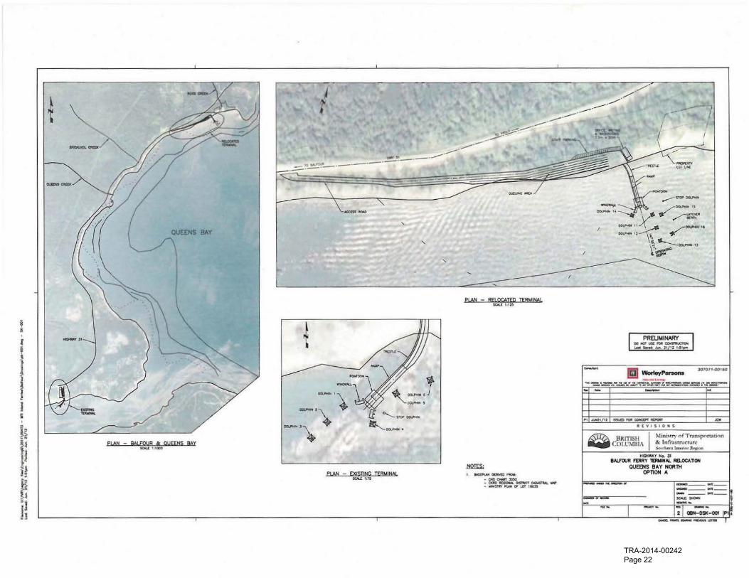
With reference to Concept Sketch No. QBN-DSK-001 in Appendix 1, a Queens Bay north ferry terminal would have direct access to Highway 31 , which is the existing two lane Provincia l highway connecting Balfour with Kaslo and communities to the north. The roadway is near the shore of Kootenay Lake but is
generally significantly above the lake level so it would be necessary to construct an access road 10 Ihe
terminal that accommodates the change in elevation. The access road would run parallel 10 both the highway and the shoreline.
The intersection between the terminal access road and Highway 31 would require a sharp lurn for traffic arriving from, or destined to the north. The provision of sufficient space for trucks to safely complete the
turn would require a large amount of grading and/or retaining walls.
The terrain is steep so a large compound is not likely to be cost effective. The roadway from the highway
to the site would need to be multiple lanes to provide vehicle queuing space while maintaining unencumbered emergency access directly to the berth . An efficient roadway design may require cutting into the bank, substantial retaining structures, and partial infill of the shoreline.
09.73 : Rev 0 : 22 June 2012 Page 7
EcoNomics TRA-2014-00242 Page 12
Worley Pa rsons resources & energy
5. TERMINAL COMPOUND
5.1 Terminal Compound
The terminal compound would require vehicle storage space for more than one sailing as one or two
sailing waits are common during peak travel periods in the summer months. The total number of spaces
would require additional studies beyond the scope of this concept report. This report assumes that a
compound would be provided with a vehicle storage capacity of approximately 160 Automobile
Equivalents (AEQs) which is twice the deck capacity of the Osprey.
The vehicle storage queue would be integral with the access road. The most economical roadway would
have two lanes from Highway 31 down to the berth ; the right lane would be used for vehicle parking and
the left lane would provide berth access for service and emergency vehicles , and for staff access to the staff parking compound. The avaitable mapping indicates that as the proposed roadway approaches the
berth, the available space widens so additional queuing space is proposed near the berth .
There would be one lane travelling from the dock up to Highway 31 . A traffic study is beyond the scope of
this report; for this conceptual report it will be assumed that a climbing lane is not required . As the ferry
route length is reduced , the efficiency of vehicle loading I unloading becomes increasing important to the
overall performance of the service. A traffic study may conclude that a climbing lane would be necessary
for efficient vessel offloading .
5.2 Buildings
The minimum amount of required ancillary buildings would include public washrooms and a foot
passenger waiting area. An operations building with storage and maintenance space would also be very
desirable. To minimize land requirements and reduce construction cost, the concept sketch shows a
single building with combined uses.
Tourist facilities and a retail I concession building or green space would be desirable but are not deemed
essential. The current concept study does not include these amenities. The inclusion of these features
would depend on the amount of land available and on the relevant business case.
Paga B 09473-0O-MA·REP-0002 RevO.doc
EcoNomics
TRA-2014-00242 Page 13
6. MARINE STRUCTURES
6.1 Site Conditions
BC MINISTRY OF TRANSPORTATION AND INFRASTRUCTURE
QUEENS BAY FERRY TERMINAL
CONCEPT STUDY
This concept report has only limited information regarding bathymetry, geotechnical conditions , and weather conditions available for the selected site.
The bathymetric information will affect the length of the required trestle and may even preclude the selected site from further consideration due to insufficient water depth. It is assumed that the water depth is such that the project is viable with a typical trestle length of approximately 30 m to 50 m.
The geotechnical conditions will affect the quantity, size, and length of piling. If rock is near the lakebed
surface, then drilling, churning , or anchoring the piles will be necessary and installation costs would increase significantly. For this concept study, the soil will be assumed to be typical lakeshore sands and gravels which provide competent support for pilings without drilling, churning, or anchoring.
:rhe exposure of the site to wind and wave actions has not been determined. The severity of exposure
may cause significant operational and safety issues with the vessel as well as severe maintenance issues with the pontoon and ramp roller system. A wind and wave study is necessary at an early stage of the project to confirm the suitability of the site. For this concept study, it is assumed that although the site is
somewhat more exposed than Balfour, a floating ferry terminal is viable. The proposed berth is shown
aligned with the southeast winds for easier manoeuvring of vessels and to minimize waves on the vessel
beam while moored at the berth.
6.2 Berth Layout
The proposed new ferry berth would serve the same vessels as the current Balfour Ferry Terminal as it is
assumed that a change of vessels is not probable in the foreseeable future. The two vessels are the
Osprey and the MV. Balfour. Although the Osprey is larger, the current dock has provided satisfactory service and demonstrated that separate operational berths are not necessary.
The new terminal layout would be similar to Balfour because there is no obvious or reported reason to significantly alter the current arrangement . Furthermore, by using a similar dock, some of the Balfour
assets may be able to be reused . The terminal would include a new shore abutment, access trestle, and ramp abutment. These structures would be completed prior to the commencement of the phased relocation and shutdown of the Balfour Terminal to mitigate service disruptions.
09473 : Rev O: 22 June2012 Page 9
EcoNomics TRA-2014-00242 Page 14
WorleyParsons resources & energy
6.3 Wingwalls
The existing Balfour wingwalls would be necessary for continued service during construction and cannot
be economically reused without a significant interruption of service or damage to the existing structure
during removal. Therefore, new wingwalls are proposed at Queens Bay. The wingwalls would have
prefabricated steel frame structures supported on steel pipe pites similar to the Balfour dolphins. The
quantity of piles and size of the frame would be larger than the line dolphins to support a required second
steel fender panel to provide a longer berthing face as per a typical wingwalL
6.4 Pontoon
The existing steel pontoon appears 10 have a significant remaining service life and reuse is considered
feasible. It should be noted that the pontoon's topside structures such as the ramp support frame and
apron hydraulic system are valuable assets that would also be reused if the pontoon were relocated .
Reusing topside assets would not only save capital cost, but would also decrease the length of service
disruption as the time to commission the system of moving parts would be minimal with the reuse of a
well-functioning system.
The pontoon mooring dolphins at Balfour are not valuable assets as they are simply clusters of vertical timber piles and are approaching the end of their service life. The pontoon mooring dolphins secure the
pontoon which also secures the vessel with two day lines and two additional night lines which are
essential for use of the Balfour berth . Therefore, the pontoon mooring dolphin piles could only be reinstalled during the shutdown of ferry service and the potential savings in material costs does not
warrant increasing the duration of the service interruption.
For reduced service disruption and project risk, pontoon mooring dolphins with new piles would be
installed at Queens Bay in advance of the phased relocation of the Balfour assets. The pontoon mooring
dolphins could be timber pile clusters or steel pipe piles, The quantity and size of piling would be
dependent on the geotechnical conditions and the expected mooring loads.
6.5 Dolphins
When construction of the Queens Bay access trestle, wingwalls, and pontoon mooring dolphins is
complete, the transition phase of relocating dolphins could commence. The construction of non-marine
structures: highway access, vehicle compound, buildings would also need to be complete or nearing completion prior to the start of dolphin relocation.
The six Balfour dolphins were constructed with steel pipe piles, prefabricated steel frames, and removable
steel fender panels during the 2000 rebuild. The structures appear to have many years of remaining
service life and have no reported serviceability issues. The dolphins could be reused without adding to the
shutdown duration provided that MTI can accept a period of some increased operating risk.
Page 10 0!M73-00-MA-REP-0002_ReVO.doc
EcoNomics
TRA-2014-00242 Page 15
BC MINISTRY OF TRANSPORTATION AND INFRASTRUCTURE
QUEENS BAY FERRY TERMINAL
CONCEPT STUDY
The proposed phasing strategy would begin with Dolphin Nos. 2 and 4 of the existing Balfour operating berth being recovered and reinstalled as Dolphin Nos. 15 and 16 at Queens Bay to provide a new layover
berth. The non-operational vessel would now relocate to Queens Bay.
The next step would be relocating Dolphin Nos. 5 and 6to the new operating berth as Dolphin Nos. 11
and 13 to prepare the Queens Bay berth for operations.
During the first two stages, the Balfour Ferry Terminal could continue to operate but the decrease in
quantity of dolphin structures does marginally increase the risk of a berthing accident. Dolphin No. 3 would
remain in service to provide ongoing mooring to the operational vessel and to provide one berthing
dolphin.
During the first two stages of the transition phase, there would also be risks introduced by having floating
construction equipment working near the operating berth to salvage the dolphins. MTI should consider temporary changes to the ferry schedule to provide longer windows of construction time for work at
Balfour to be safer and more cost effective.
6.6 Ramp and Pontoon Relocation
When four of the six Balfour dolphins have been relocated, the project would be ready for a brief shutdown period with no ferry service. The ramp and apron would be removed from Balfour and floated to Queens Bay on a barge. The pontoon would be disconnected from the Balfour mooring dolphins, towed to Queens Bay, and reinstalled. The ramp would be reinstalled on the Queens Bay ramp abutment and relocated pontoon and then re--commissioned for renewed service. With thorough preplanning, advance preparation
and favourable weather, a 60 hour (two days and three nights) shutdown duration is a reasonable schedule for an experienced marine contractor.
6.7 Project Completion and Balfour Decommissioning
After the commencement of service at Queens Bay, Dolphin Nos. 1 and 3 at Balfour would be relocated to
Dolphin Nos. 12 and 14 to complete the relocation of salvageable Balfour assets. The remaining Balfour
marine structures: the wingwalls, pontoon mooring dolphins, ramp abutment and access trestle, would be removed.
Depending on future use of the site, the access trestle could be retained as a public amenity. The extent
of removal of the holding compound , buildings, and parking lots would be determined by the future use of the site. Complete removal of all uplands structures to bare ground is not considered to be a major undertaking.
The extent of ground contamination is not known, however, some remediation may be necessary due to the factlhal the site has been used for many years. No allowance has been made for the cost of
environmental remediation of the exisling terminal compound.
09473 : Rev 0 : 22 June 2012 Pall,e 11
EcoNomlc~
TRA-2014-00242 Page 16
Worley Parsons resources & energy
7. CONCEPTUAL COST ESTIMATE
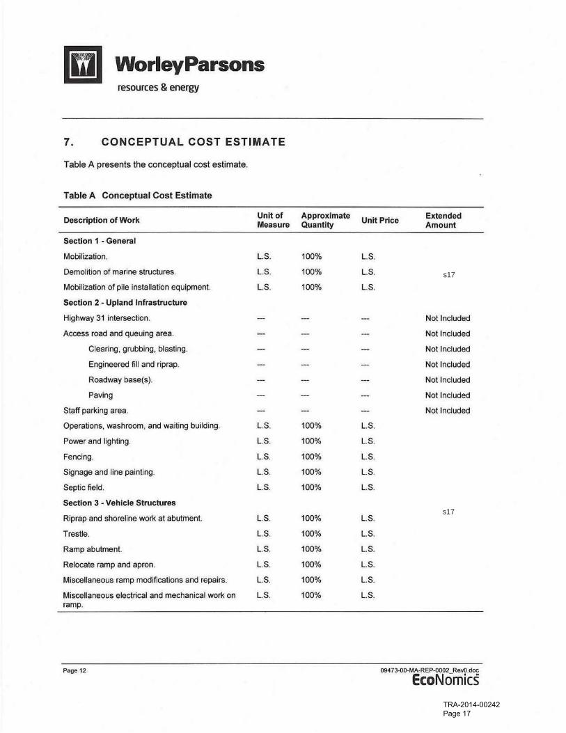
Table A presents the conceptual cost estimate.
Table A Conceptual Cost Estimate
Description of Work Unit of Approximate Unit Price
Extended Measure Quantity Amount
Section 1 - General
Mobilization. L.S. 100% LS.
Demolition of marine structures. L.S. 100% l.S.
Mobilization of pile installation equipment. L.S. 100% loS.
Section 2 - Upland Infrastructure
Highway 31 intersection. Nollnduded
Access road and queuing area. Not Included
Clearing, grubbing, blasting. Not Included
Engineered fill and riprap. Not Included
Roadway base(s). Not Included
Paving Not Included
Staff parking area, Not Included
Operations, washroom, and waiting building. L.S. 100% L.S.
Power and lighting. LS. 100% LS.
Fencing. LS. 100% LS.
Signage and line painting. LS, 100% LS.
Septic field. L S. 100% LS.
Section 3 • Vehicle Structures
Riprap and shoreline work at abutment. LS. 100% LS.
Trestle. LS. 100% LS.
Ramp abutment. LS. 100% LS.
Relocate ramp and apron. L.S. 100% LS.
Miscellaneous ramp modifications and repairs. L.S. 100% LS.
Miscellaneous electrical and mechanical work on L.S. 100% LS. ramp.
Page 12 09-473-0O-MA·REP-0002 ReVO.doc
EcoNomics
TRA-2014-00242 Page 17
s17
s17
BC MINISTRY OF TRANSPORTATION AND INFRASTRUCTURE
QUEENS BAY FERRY TERMINAL
CONCEPT STUDY
Description of Work Unit of Approximate Unit Price Extended
Measure Quantity Amount
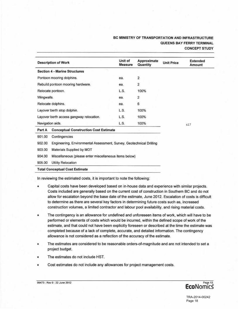
Section 4 - Marine Structures
Pontoon mooring dolphins_ ea. 2
Rebuild pontoon mooring hardware. ea 2
Relocate pontoon. L.S. 100%
VVingwalis. ea. 2
Relocate dolphins. ea. 6
l ayover berth stop dolphin. L.S. 100%
layover berth access gangway relocation. L.S. 100%
Nayigation aids. L. S. 100%
Part A Conceptual Construction Cost Estimate
901.00 Contingencies
902.00 Engineering, EnYironmental Assessment, Survey, Geotechnical Drilling
903.00 Materials Supplied by MOT
904.00 Miscellaneous (please enter miscellaneous items below)
905.00 Utility Relocation
Total Conceptual Cost Estimate
In reviewing the estimated costs, it is important to note the following:
• Capital costs have been developed based on in-house data and experience with similar projects.
Costs included are generally based on the current cost of construction in Southern BC and do not
allow for escalation beyond the base date of the estimate, June 2012. Escalation of costs is difficult
to determine as there are several key factors in determining future costs such as, increased
construction volumes, a limited contractor and labour pool ayailability , and rising material costs.
• The contingency is an allowance for undefined and unforeseen items of work, which will have to be
performed or elements of costs which would be incurred, within the defined scope of .work of the
estimate, and that could not have been explicitly foreseen or described at the time the estimate was
completed because of a lack of complete, accurate, and detailed information. The contingency
allowance is not considered as a reflection of the accuracy of the estimate.
• The estimates are considered to be reasonable orders-of-magnitude and are not intended to set a
project budget.
• The estimates do not include HST.
• Cost estimates do not include any allowances for project management costs.
09473 : Rev o · 22 JUnfI 2012 Page 13
EcoNomics TRA-2014-00242 Page 18
s17
Worley Parsons resources & energy
• Cost estimates do not inClude any allowances for regular maintenance, upgrades, or further
remedial measures.
•
•
Page 14
The estimate is based on in-house experience with similar projects and on budget price quotations
from local contractors and suppliers, and assumes a competitive bidding process.
The estimate is based on replacement of structural elements with similar type and size of materials.
~73-0O-MA-REP-0002_RevO .doc
EcoNomics
TRA-2014-00242 Page 19
8. SUMMARY
BC MINISTRY OF TRANSPORTATION AND INFRASTRUCTURE
QUEENS BAY FERRY TERMINAL
CONCEPT STUDY
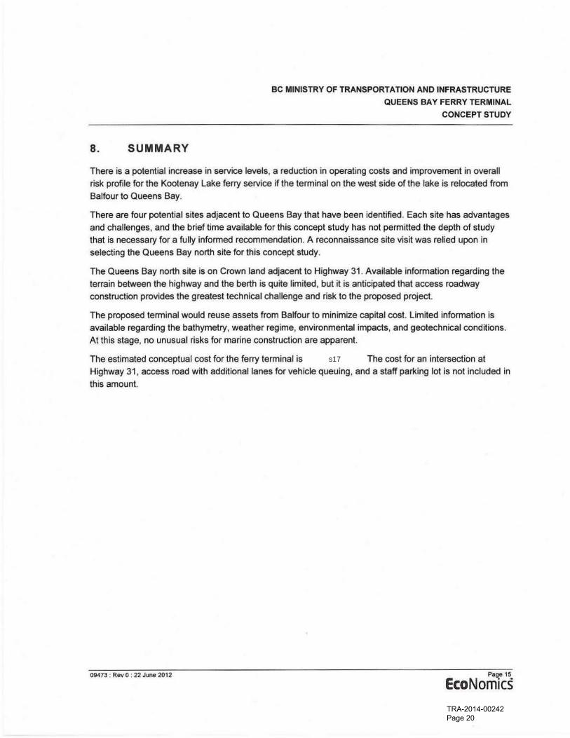
There is a potential increase in service levels, a reduction in operating costs and improvement in overall
risk profile for the Kootenay Lake ferry service if the terminal on the west side of the lake is relocated from Balfour to Queens Bay.
There are four potential sites adjacent to Queens Bay that have been identified. Each site has advantages and challenges , and the brief time available for this concepl study has not permitted the depth of study that is necessary for a fully informed recommendation. A reconnaissance site visit was relied upon in selecting the Queens Bay north site for this concept study.
The Queens Bay north site is on Crown land adjacent to Highway 31 . Available information regarding the terrain between the highway and the berth is quite limited, but it is anticipated that access roadway construction provides the greatest technical challenge and risk to the proposed project.
The proposed terminal would reuse assets from Balfour to minimize capital cost. limited information is
available regarding the bathymetry, weather regime, environmental impacts, and geotechnical conditions . At this stage, no unusual risks for marine construction are apparent.
The estimated conceptual cost for the ferry terminal is The cost for an intersection at
Highway 31 , access road with additional lanes for vehicle queuing, and a staff parking lot is not included in
this amount.
09473 , Rev 0: 22 June 2012 P'g:e 15
EcoNomics TRA-2014-00242 Page 20
s17

Appendix 1 Sketch
09<173 : Rev 0 : 22 June 2012
BC MINISTRY OF TRANSPORTATION AND INFRASTRUCTURE
QUEENS BAY FERRY TERMINAL
CONCEPT STUDY
Appendice1;
EcoNomics TRA-2014-00242 Page 21
I !
, " I
, I
~ iii ~ } i
I "
" ".. I
,A
i,A
I
5 I
TRA-2014-00242 Page 22
Top Related