


Languages
Pages
Legal


P/N: QSD 101 – ENG – Rev 2 – 2012

I
Chapter 1 First Steps
1.1 Know the QSV 1
1.1.1 Front panel 1
1.1.2 Connectors 2
1.2 Install or replace batteries 3
1.3 Connecting the transducer 5
1.4 The “Q” key 6
1.5 Display illumination and contrast 6
1.5.1 Display backlight illumination 6
1.5.2 Display contrast 7
1.6 Locking and unlocking the keypad 7
Chapter 2 Measuring with the QSV
2.1 Measuring screen 9
2.2 Keys in the measuring mode 10
2.3 Zero calibration (Auto) 12
2.4 Measuring the material velocity 13
2.4.1 Measuring velocity with the caliper
connected to the unit
13
2.4.2 Measuring velocity using a known
thickness value
14
2.5 Measuring thickness with a known velocity 15
Chapter 3 Menu system and editing
3.1 Instructions on using the menu system 16
3.2 Main menu 17
3.3 Change measuring unit 17
3.4 Alarm settings 17
3.5 Memory settings 18
3.5.1 Connecting to a PC with DataCenter 18
3.5.2 View stored values 19
3.5.3 Erase memory 20

II
3.5.4 Capture modes 21
3.5.5 Available memory 21
3.6 Caliper selection 22
3.6.1 Connecting the caliper 22
3.7 General configuration options 23
3.7.1 Select language 23
3.7.2 Set keypad sensitivity 24
3.7.3 Adjust gain 25
3.7.4 Adjust pulser excitation voltage 25
3.7.5 Set auto-off time 26
3.7.6 Adjust display contrast 26
3.7.7 Beep activation 27
3.7.8 Hold last value 27
3.7.9 Model upgrade licenses 28
3.7.9 Unit information 30
Tips on how to measure correctly
Technical specifications
Additional information
Unit maintenance
QSV accessories
Error messages
Our website: www.demeq.com
Technical support

III
And thank you for purchasing a QSV ultrasonic velocity gauge.
At dmq we develop, manufacture and distribute software and quality
control instruments offering innovation and solutions that come as a
direct result of listening to your needs as a user. We apply some of the
latest technology available in the industry to build instruments that are
robust, precise, and easy to operate.
We are convinced that our products would not be complete without
permanent technical and after sales support. So in addition to a great
product we offer:
Quick answers to your inquiries.
Unlimited access to technical information as well as
application notes.
Special offers for registered customers.
Firmware and software upgrades at no charge.
Attention to your inquiries and suggestions.
We hope that the QSV will meet and exceed your application needs.

IV
The information included in this manual applies to the QSV ultrasonic
velocity gauge only.
dmq is a registered trademark of demeq S.R.L and its affiliate
companies.
The information contained in this manual is intended to educate users
on the operation of the QSV velocity gauge. Failure to read and
understand this manual can lead to measurement errors. Decisions
based on measurements and or results that are erroneous can lead to
property damage, personal injury or even death. Demeq S.R.L assumes
no responsibility as a result of the improper use of our instruments.
ASTM E797
The user must be trained in ultrasonic testing procedures and on how
to properly configure the unit for testing. All of the following should
be taken into consideration:
Understand the theory on sound wave propagation.
Select the transducer that is best suited for your application.
Know the specific requirements for the test you will be
conducting.
This manual provides all of the information needed to configure and
operate the QSV velocity gauge. However there are additional factors
that can affect tests done with this instrument. Specific information on
those factors is outside the scope of this manual. When in doubt you

V
should always seek expert advice or refer to specific textbooks on
measuring the sound velocity of materials using an ultrasonic velocity
gauge. Additional information can also be found on the internet and
through local government agencies as well as in technical institutes.
The QSV operates with dual crystal transducers that use the “pitch-
catch” principal. Dual crystal transducers use two piezoelectric crystals
whereby one crystal is excited with short electrical pulses from the unit
sending short acoustic waves into the test piece. The second crystal
then receives the acoustic waves reflected at the end of the test piece.
The frequency of the acoustic waves changes between 2 and 10 MHz
depending on the probe being used.
Figure 1: Transducer signals (acoustic wave representation)

VI
In ultrasonic testing information is obtained from measuring sound
waves. Users must be very careful when making assumptions in
regards to the entire test piece condition when there are areas that
have not been inspected. In large and massive test pieces it would be
practically impossible to test the entire piece and therefore conclusions
for the whole piece based solely on the areas that have actually been
inspected, should only be done by experienced operators.
In order to minimize test result errors the following must be observed:
Before taking actual measurements the unit and transducer have to be
calibrated. Calibration of the transducer is also known as zero
calibration or delay calibration (Page 11). If the unit and transducer are
not calibrated, or calibrated incorrectly, the resulting measurements
will be unreliable. Each and every time a transducer is changed it must
be calibrated to the unit.
Because the sound velocities in materials will often vary significantly
from published values, best results are obtained when the instrument
is calibrated on a reference test block made from the same material as
that of the actual test piece. The block should be flat, of a smooth
finish, and be as thick as the maximum thickness of the test piece.
Careful consideration by the user must be made when evaluating the
accuracy of a thickness value because considerable changes in the
sound velocity of a material may have occurred as a result of a
treatment. So for example a test piece made of steel that has been
thermally treated, will look the same as a regular test piece made of
untreated steel, but the sound velocities vary significantly. Instruments
should be calibrated before and after testing to minimize errors.

VII
Transducers must be in good condition and show no visible signs of
excessive wear or defects on their surface. Badly worn transducers can
provide erroneous measurements.
The thickness of the material being tested must be within the specified
thickness range of the transducer and the temperature of the material
must also be within the specified temperature range of the transducer.
Calibration as well as actual testing should be performed under similar
coupling conditions. Couplant must be applied in an even and
consistent manner to minimize variations in couplant layers that may
result in testing errors. The amount of couplant should be kept to a
minimum and consistent pressure should be applied on the transducer
when measuring.
Doubling refers to a thickness measurement that displays a reading that is twice or even three times the real test piece thickness. Doubling often may happen when trying to measure below and above the specified range for the transducer and when using worn transducers. When in doubt, the test piece thickness must be measured using other methods and or instruments and the unit must then be calibrated using reference test blocks of known thickness values that are made of the same material as the actual test piece. This is very important when measuring unknown test pieces for the first time.
When possible calibrate your instrument on-site using a test block that
is at the same temperature as the test piece in order to minimize
errors.

VIII
QSV ultrasonic velocity gauges are for industrial use only and cannot
be used in medical applications. The QSV operates on two AA size
batteries. We strongly recommend that you use only top brand name
alkaline batteries.
Disposal of your QSV gauge and its components must be done in
compliance with all applicable regulations.
Because of its complexity level, software is never really completely error
free. For this reason in software controlled instruments always make
sure that the operations required for your application are in correct
working order.
Demeq S.R.L provides a limited warranty for a period of 2 (two) years
on electronic units and for 6 (six) months on transducers from the date
of purchase and may be extended for up to 5 years.
Every instrument undergoes thorough testing during manufacturing as
well as before shipping. In the event warranty service where to become
necessary, dmq and or your local distributor or representative will
make a reasonable effort to replace your defective unit with another
new or used unit, while your instrument undergoes warranty repair.

Chapter 1 1
Figure 1.1: Front of the unit
1. Graphic LCD display with LED backlight illumination
2. Move Left key
3. Move Up key
4. Menu key / Enter and exit measure screen / Exit and return to
menus (Home)
5. Enter key / Edit values on the measure screen (Edit)
6. Move Down key / / Manually store a value (Store)

2 Chapter 1
7. Change backlight illumination key (On, Off, Auto)
8. The key: Power On and Shutdown (touch and hold for 2
seconds) / Make quick and short touches to activate special
functions and features
9. Calibration block
10. Horizontal scrolling center point (lock and unlock keypad on
measure screen)
11. Vertical scrolling center point (adjust LCD contrast)
Figure 1.2: Unit connectors
1. Receiving transducer connector (Type Lemo 00)
2. Emitting transducer connector (Type Lemo 00)
3. USB mini connector to connect to PC using a USB cable
(supplied with the unit). This same USB connector is also
used to connect the digital caliper interface so that the
caliper and the unit can communicate.

Chapter 1 3
The QSV is powered by 2 (two) AA batteries that are placed in the
battery compartment located in the back of the unit. To access to the
battery compartment slide the cover as shown in figure 1.3-1 and
gently push the extraction ribbon upward and slightly towards the
right to release the batteries (figure 1.3-2).
When you install new batteries, first insert the positive end of each
battery so that it coincides with the positive pole inside the battery
compartment as you see in figure 1.4-1. Always leave the extraction
ribbon underneath the batteries.
Figure 1.3: Removing batteries

4 Chapter 1
Figure 1.4: Replace / Insert batteries
Notes Use new alkaline top brand batteries only.
Do not mix new and old batteries. Always replace both
batteries.
Rechargeable batteries type NiMH can be used but will
result in less time of continuous operation.

Chapter 1 5
Important Do not remove batteries while the unit is powered as
this may affect the Data logger (See Appendix:
“Additional information, Error Messages”)
The QSV has two type Lemo “00” connectors located on top of the
unit. Because this is the standard for most dual crystal probes, you
could basically connect any probe to your QSV. Keep in mind that the
gain may need to be adjusted when changing probes.
To connect the probe, simply align any
of the male connectors located at the
end of the transducer cable to any of
the female connectors located on the
gauge and press gently until
connected.
To release the probe hold the knurled
section on the male connectors and
pull gently away from gauge until
released.
Figure 1.5: Connecting the transducer

6 Chapter 1
The has three functions:
When the unit is off, touch for 2 seconds to power on
the unit.
When the unit is on, touch for 2 seconds to shutdown
the unit.
With the unit on, making short touches to the will
activate special functions described in later chapters of this
manual.
Backlight illumination and contrast options can be changed from any
screen in the unit.
Touch to change the backlight illumination settings.
Figure 1.6: Backlight illumination options

Chapter 1 7
The display contrast on all dmq units is digital.
Touch the white dot located in the center of
the vertical scrolling bar between the -
keys and a contrast window will open.
Move your finger towards the top and or
bottom of the dotted line to adjust the contrast
on your display.
Figure 1.7: Display contrast adjustment
To lock the keypad place your finger on the white dot located in the
center of the horizontal scrolling bar between the - keys.
Move your finger to the right following the dotted line and a window
on the unit display will open with the word Lock. Continue moving
your finger in the same direction until you enter locked mode. The
window on the display will close and the locked keypad indicator will
show on the top right of the unit screen.
Figure 1.8: Locking the keypad

8 Chapter 1
Sliding the finger to the left will unlock the keypad.
Figure 1.9: Unlocking the keypad
\ Important The keypad can only be locked and unlocked in the
measuring screens.
Chapter 2 9
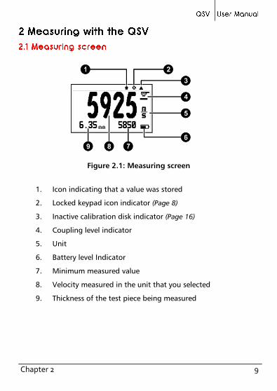
Figure 2.1: Measuring screen
1. Icon indicating that a value was stored
2. Locked keypad icon indicator (Page 8)
3. Inactive calibration disk indicator (Page 16)
4. Coupling level indicator
5. Unit
6. Battery level Indicator
7. Minimum measured value
8. Velocity measured in the unit that you selected
9. Thickness of the test piece being measured

10 Chapter 2
Keys in the measuring screen have the following functionality:
: Touch to exit the measure screen and enter the main menu.
: Touch to manually store the measurement in the memory.
: Touch to activate the Select / Edit mode. Two flashing arrows
will appear over the fields of velocity and thickness.
Touch to select velocity.
Toque to select test piece
thickness.
Always use the - keys to edit the
values in any given field and touch to
save.
Figure 2.2: Measuring screen in select / edit mode
Notes The velocity field can only be edited if an actual
measurement was taken. If the velocity is 0 this field
cannot be edited.
When a measurement was taken and the velocity is
changed, a new thickness measurement for the new
velocity is automatically displayed.

Chapter 2 11
Tips
Touch the when editing velocity and a screen will
appear with the most commonly used materials and
their velocities as seen in (Figure 2.3).
Figure 2.3: Materials velocity list table
Use the - keys to scroll the list and touch to select or
touch to exit and return to the edit velocity field.
: With a short touch the minimum measured value is reset to 0.
Touch for 2 or more seconds to shutdown the unit.
: Changes the backlight illumination.
: Adjust display contrast.
: Lock and unlock the keypad.

12 Chapter 2
The QSV uses a zero (delay) calibration procedure that is activated by
simply coupling the transducer over the calibration disk located in
front of the unit.
Figure 2.4: Zero calibration procedure
When this automatic procedure ends, the unit is calibrated to measure
steel which is the default material velocity used in this calibration
method.
Tip In order to measure the thickness of the calibration disk
without activating the automatic calibration procedure
simple touch the edge of the disk until an icon appears
as shown in (Figure 2.1, 3. Inactive calibration disk
indicator, Page 9) While still touching the edge of the
disk, couple the transducer to obtain its thickness
measurement. When the transducer is coupled you no
longer need to touch the edge of the disk.

Chapter 2 13
With a QSV-DLC you can connect a caliper to the unit that is used to
measure the test piece thickness. In order to measure sound velocity
you must always know the part thickness. The measuring procedure is
explained below:
Measure the test piece thickness with the caliper connected
to the QSV. The value in the caliper will appear in the unit
display.
Touch the key to save the thickness value from the
caliper to the unit. At this point in time changing the
thickness value of the caliper will no affect the saved
measurement.
Measure the sound velocity placing the transducer on the
exact same place where the thickness measurement was
taken with the caliper.
Figure 2.5: Using a caliper to measure thickness

14 Chapter 2
The thickness that you saved to the unit will only be changed when a
new thickness is measured with the caliper and saved.
If you do not know the velocity of the material but you know the
material thickness you can set the velocity using the material thickness
value by doing the following:
Measure the material for which you already know the
thickness.
Lift the transducer and touch to enter the Select / Edit
mode.
Touch to edit the thickness measurement field.
Use the cursors to set the velocity and touch to confirm
or touch to cancel.
When editing the thickness value observe that the velocity will change
accordingly.
Note When changing the material velocity using a known
thickness value the unit must have already been
calibrated for the transducer being used (Page 11).

Chapter 2 15
If you know the velocity of the material you will be measuring you can
manually enter the velocity by doing the following:
Go to the measuring screen.
Touch to enter the Select / Edit mode.
Touch to edit the velocity field.
Use the cursors to set the velocity and touch to confirm
or touch to cancel.
Tips
Touch the when editing velocity and a screen will
appear with the most commonly used materials and
their velocities. Use the cursor keys to scroll the list and
touch to select or touch to exit and return to
the edit velocity field.

Chapter 3 16
The instructions explained in this chapter apply to all of the menus in
the unit.
To scroll QSV menu options use the - cursor keys. When you
reach the end of the menu and move to the next menu option it
becomes circular as shown below.
Figure 3.1: Example of how a circular menu works
To select a menu option touch and to exit and return to the
previous menu touch . To go to the measuring screen touch
from the main menu.
Figure 3.2: The “Home” key from the measuring screen

Chapter 3 17
The main menu is the first list of options that
appears when you exit the measure screen
and it includes the most important settings.
Touch from the measuring screen to
access this menu.
Figure 3.3: Main menu
Each main menu option is explained in the following items.
Touch on Unit in the main menu to open the list of available
units.
Use the - keys to scroll the menu.
Touch to select the unit and touch
to save and exit this menu.
Figure 3.4: Units menu
The QSV has high and low alarms that alert the operator when the
measurement is greater than the value set for the high alarm and or
when the measurement falls below the value set for the low alarm.
Touch on Alarms to open the alarm menu options.

18 Chapter 3
Touch on High or Low to open the
numbers editor where you can set alarm
values using the cursor keys.
Touch to save the alarm value that you
entered and to return to the previous menu.
Figure 3.5: Alarm menu options
Any of the following alarm types can be selected:
Beep: Audible intermittent alarm type.
Screen: Visible alarm that causes measurements to be displayed in
dotted instead of regular numbers.
Light: Visible alarm that activates the display backlight illumination
causing it to flash.
Select Memory from the main menu to view
all menu options for the Data logger. The
QSV can store up to 5000 values that can be
viewed on the unit display and or transferred
to a PC via USB using dmq DataCenter.
Figure 3.6: Memory menu options
Touch on Connect to enter the “waiting to connect” mode.
Touch to exit and cancel the connection.

Chapter 3 19
Figure 3.7: Connecting to a PC
With the unit in “waiting to connect” make sure that the USB or the
RS232 cable (depending on the type of connecting cable that you are
using) is properly connected to both the unit and the PC and click on
<Connect> in DataCenter.
When a successful connection is established the files in your unit
memory will appear in DataCenter. To view their contents simply
double click on each file.
For additional information on dmq DataCenter software refer to the
manual included in the CD that you received with your QSV or
download the manual at http://www.demeq.com/Download.html
Touch on View Data to view the
contents of the file. Touch to exit the
file.
Figure 3.8: File view in a grid format
The QSV stores values in groups of 100 measurements. This means
that every 100 measurements, a new lot is created (lots are indicated
by letters).

20 Chapter 3
The Erase action permanently deletes all files stored in the unit
memory and recovers 100% of the memory capacity.
Before files are deleted, a screen will be displayed asking you to
confirm or to cancel this action.
Touch to cancel and return to the
previous menu or touch to begin
deleting all files.
Figure 3.9: Erase All confirmation screen
When the erase all action has been confirmed the following screens
will be displayed:
Figure 3.10: Erase All progress screens
After this process is completed all of the cells in the grid will be empty.

Chapter 3 21
Touch on Capture to select the mode in
which values will be stored in the Data logger.
Figure 3.11: Memory capture modes menu
The QSV has the following capture modes:
Manual: Touch the key to store values.
Auto: When the transducer is coupled measurements are continuously
stored.
Free memory is followed by a number representing the remaining
memory that is available to store data and is represented in number of
cells.
Touch on Free to view the remaining number of free cells and
the free memory space as a percentage of the unit total memory.
Figure 3.12: Remaining memory screens

22 Chapter 3
This menu gives you two options for use of a
caliper connected to the QSV. Enable
Activate by touching the key to use the
caliper and manually save thickness
measurements from the caliper to the QSV.
Figure 3.13: Caliper options menu
In Auto Thickness mode the measurements that you take with the
caliper are automatically saved to the unit until the transducer is
coupled. To enable this option touch .
A caliper can only be used with the QSV DLC model.
To connect the caliper to the QSV electronic unit use the interface
cable (provided with the unit) and connect one end of the cable to
unit and the other end to the caliper.
Figure 3.14: Connecting the caliper to the QSV
Chapter 3 23
The cable has two LEDS indicating the connection has been
established.
The QSV will read values obtained with the caliper when the same
measuring unit (metric / inch) is set on both the unit and the caliper.
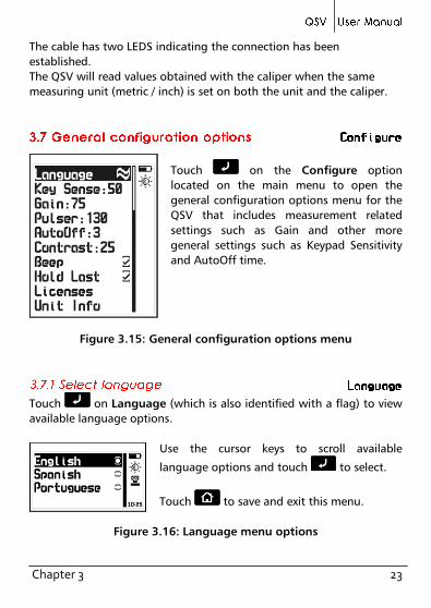
Touch on the Configure option
located on the main menu to open the
general configuration options menu for the
QSV that includes measurement related
settings such as Gain and other more
general settings such as Keypad Sensitivity
and AutoOff time.
Figure 3.15: General configuration options menu
Touch on Language (which is also identified with a flag) to view
available language options.
Use the cursor keys to scroll available
language options and touch to select.
Touch to save and exit this menu.
Figure 3.16: Language menu options
24 Chapter 3
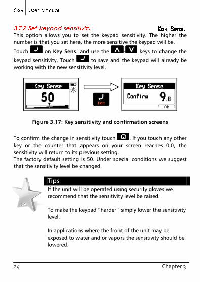
This option allows you to set the keypad sensitivity. The higher the
number is that you set here, the more sensitive the keypad will be.
Touch on Key Sens. and use the - keys to change the
keypad sensitivity. Touch to save and the keypad will already be
working with the new sensitivity level.
Figure 3.17: Key sensitivity and confirmation screens
To confirm the change in sensitivity touch . If you touch any other
key or the counter that appears on your screen reaches 0.0, the
sensitivity will return to its previous setting.
The factory default setting is 50. Under special conditions we suggest
that the sensitivity level be changed.
Tips If the unit will be operated using security gloves we
recommend that the sensitivity level be raised.
To make the keypad “harder” simply lower the sensitivity
level.
In applications where the front of the unit may be
exposed to water and or vapors the sensitivity should be
lowered.

Chapter 3 25
Touch on Gain to change the gain level (signal sensitivity). The
higher the gain the more sensitive the unit will be making it easier to
measure lower thickness values. But excessive gain can also cause
erroneous measurements.
The gain is typically adjusted when changing transducers.
Touch the - keys to adjust the gain
value and touch to save and exit.
Touch to exit without making changes.
Figure 3.18: Adjust gain level
Touch on Pulser to adjust the transducer pulser excitation level.
Touch the - keys to adjust the
tension and touch to save and exit. To
exit without changes touch .
Figure 3.19: Transducer pulser excitation tension editor screen
Considerations when adjusting the pulser excitation tension:
Higher excitation levels mean that more energy is applied to the
emission crystal in the transducer which allows for better penetration
in high attenuation and large or thick materials.

26 Chapter 3
When measuring small or thin materials high tensions produce
saturated echoes that can affect measurement results.
Avoid high tensions especially in small diameter transducers as this
could damage the transducer. For the standard 5MHz transducer the
tension should not exceed 150V. Large diameter transducers can be set
to higher tensions.
The unit will shutdown automatically if no key is touched or no
measurement is made when you set the auto-off time.
Touch on AutoOff to set the time before the unit automatically
shutdown.
Touch the - keys to set the time and
touch to save and exit.
Touch to exit without making changes.
Figure 3.20: AutoOff time
Use this setting to adjust the screen contrast making it lighter or
darker where 1 is the lightest and 32 is the darkest.
Touch on Contrast and use the - keys to change the
contrast on your screen.

Chapter 3 27
Touch to save or touch to exit without making changes.
Figure 3.21: Screen contrast settings
Tips
Contrast on LCD screens can change with temperature.
Use the contrast option to compensate for changes
caused by temperature in order to maintain optimal
viewing conditions.
Beep refers to the sounds that the unit makes when keys are touched
and when the audible alarm is activated.
Touch to enable or disable the beep option.
When you enable the Hold last option the last measured value will be
displayed on the unit screen even when the transducer is not coupled.
When hold last is disabled and the transducer is not coupled the unit
display will read "-----".

28 Chapter 3
Touch to enable or disable this option.
Figure 3.22: Measuring screen with hold last enabled or disabled
QSV models can be changed with the purchase of model upgrade
licenses available from dmq.
In order to purchase a license you must provide all of the following
information:
Unit model
Unit serial number
The type of license that you would like to purchase
Touch on Licenses to view all licenses available for your unit,
active licenses are indicated with checkmarks.
To enter the new license number that you
purchased from dmq touch or to exit
and return to the previous menu touch .
Figure 3.23: License status screen

Chapter 3 29
Use the cursor keys to enter the license
number and touch to save.
Figure 3.24: Enter new license number screen
After entering your new license number the unit will respond with one
of the following messages:
Figure 3.25: Response messages after a license is entered
If the license number that you entered is correct the unit will show an
updated license screen that will include your newly activated license
(now followed by a checkmark).

30 Chapter 3
Touch on Unit Info to view the hardware and software versions
in your unit.
To view different unit information screens touch the - keys.
To return to the main menu touch .
Figure 3.26: QSV unit information screens

Chapter 3 31
Do not measure outside the thickness range specified for the
transducer that you are using.
Use just enough coupling gel to ensure stable measurements. Avoid
using excessive coupling gel as it may be added to the thickness value
of the actual test piece being measured.
Always do the zero calibration using the calibration disk located in the
front of the unit particularly when changing transducers.
Know the velocity of the material you will be measuring or have a
reference test piece made of the same material you will be measuring
and of a known thickness value so that you can precisely determine
the material velocity based on its thickness.
Gain levels are set from factory with the optimal values that
correspond to the transducer that was shipped with your unit. When a
transducer is changed gain will usually need to be adjusted to optimize
transducer functionality.

Apendix
Measuring principal Pulse-Echo
Measuring range 100 m/s a 19999 m/s
Transducer frequency 2 to 10 MHz
Measuring frequency 4 Hz
Pulser tension Adjustable 20 V to 210 V
V-Path Automatic correction.
Units Millimeters and Inches.
Resolution 1 m/S from 100 to 19999 m/s
0,1 in/ms from 4,0 to 787,0 in/ms
Material thickness 1 to 500 mm
0,040 to 19,68 in
Calibration Auto 1-Point..
Alarms Minimum.
Audible and visual.
Languages English, Spanish, Portuguese.
Data logger Up to 5000 values.
Manual and Continuous capture modes.
View data in grid or graphic formats.
Display Graphic LCD 128 x 64 pixels with LED
backlight illumination and digital contrast
adjustment.
Keypad Touch-sense with no mechanical parts and
sensitivity adjustment.
Battery life 100 hours with 2 each type AA batteries
Operating temp. - 10°C to + 50°C
Enclosure High impact ABS with rubber sides. Size is
78 x 117 x 24 mm.
Weight 200 g with batteries

Apendix
The QSV was developed and manufactured for years of trouble free
operation and even though the unit does not require special care the
following precautions should be considered:
Avoid contact with corrosive and abrasive substances.
Do not clean the unit with solvents.
Do not leave the unit display exposed to direct solar light for
prolonged periods of time as this could damage the display.
Remove the batteries if the unit will be stored for an
extended period of time.
Remove the transducer using the connectors and not the
cable.
Do not twist or strangle transducer cable.
Do not expose the unit to temperatures below -10°C / 14°F or
above 50°C / 122°F.

Apendix
dmq part No. Description
QSM 300 Small high impact carrying case
QSC 003 InSize caliper interface cable
QSC 004 Mitutoyo caliper interface cable
QSS 201 2Mhz transducer – 15 mm diameter
QSS 501 5Mhz standard transducer – 10 mm diameter
QSS 701 7Mhz transducer – 5 mm diameter
QSR 161 6 step calibration block (mm)
QSR 141 4 step calibration block (in)
QSG 001 Coupling gel (small)
QSG 002 Coupling gel (large)
QAC 002 RS232 cable to connect to a PC
QAC 003 RS232 cable to connect to a printer

Apendix
Error messages may eventually open on your unit screen and are
informational only. If one of these messages opens on your display
follow the instructions described below and if the problem persists
please send us a detailed report at
www.demeq.com/form_Support.html
Figure A.2: System error message
Error 1 Internal Error
Cause Internal Error
Solutions Shutdown the unit, wait a few seconds, and power
back on.
Contact dmq.
Error 2 Attempt to store a value over an existing value.
Cause Improper unit shutdown (Example: Removing
batteries) and powering the unit back on to store
values in the Data Logger.
Solution Download Data Logger values to PC or printer and
erase memory.
If a message with a different number where to appear please contact dmq.

Apendix
Our website is a powerful customer support tool where you will find
the latest information as it relates to your QSV including:
Application notes
Manuals and brochures
New accessories
Our service department is committed to providing prompt and
courteous service. Should you encounter any issues with your QSV
please send us a detailed description of your problem to
www.demeq.com/form_Support.html

P/N QSD-101-ENG-Rev 2-2012 ©2012 dmq
Top Related