


Languages
Pages
Legal


TroubleshootingGuide
Bulletin 1336 PLUSAdjustable FrequencyAC Drive Series A, B, C, DB300 – B600BX250C300 – C600
Allen-Bradley
Important User Information
ATTENTION: Identifies information about practices orcircumstances that can lead to personal injury or death, propertydamage or economic loss.
Attentions help you:
• Identify a hazard.
• Avoid the hazard.
• Recognize the consequences.
IMPORTANT: Identifies information that is especially important forsuccessful application and understanding of the product.
DANGER labels may be located on or inside the drive to alertpeople that dangerous voltage may be present.

Summary of Changes
The information below summarizes the changes to the company-widetemplates since the last release.
Updated Information Information has been added to Overtemp Fault 08 in Table 2.A on page 2-6.
An illustration has been added on page 4-11.
Table 4.F on page 4-16 has been changed.

Summary of Changes
This Page Intentionally Left Blank

Table of Contents
i
Preface
Manual Objective P-1. . . . . . . . . . . . . . . . . . . . . . . . . . . . . . . . . . . . . . . . . .
Who Should Use This Manual P-1. . . . . . . . . . . . . . . . . . . . . . . . . . . . . . . .
Safety Precautions P-1. . . . . . . . . . . . . . . . . . . . . . . . . . . . . . . . . . . . . . . . .
Electrostatic Discharge Precautions P-2. . . . . . . . . . . . . . . . . . . . . . . . . . . .
1336 PLUS Product Identification P-3. . . . . . . . . . . . . . . . . . . . . . . . . . . . .
Drive Nameplate Location P-3. . . . . . . . . . . . . . . . . . . . . . . . . . . . . . . .
Software Compatibility P-4. . . . . . . . . . . . . . . . . . . . . . . . . . . . . . . . . .
Drive and Option Identification P-5. . . . . . . . . . . . . . . . . . . . . . . . . . . . . . .
1336 PLUS Drive Catalog Numbers P-5. . . . . . . . . . . . . . . . . . . . . . . .
Drive Rating Qualifications P-9. . . . . . . . . . . . . . . . . . . . . . . . . . . . . . .
Enclosure Type P-9. . . . . . . . . . . . . . . . . . . . . . . . . . . . . . . . . . . . . . . .
Conventions P-10. . . . . . . . . . . . . . . . . . . . . . . . . . . . . . . . . . . . . . . . . . . . .
Related Publications P-12. . . . . . . . . . . . . . . . . . . . . . . . . . . . . . . . . . . . . .
Control Logic Wiring Chapter 1and Adapters
Chapter Objectives 1-1. . . . . . . . . . . . . . . . . . . . . . . . . . . . . . . . . . . . . . . . . .
Chapter Overview 1-1. . . . . . . . . . . . . . . . . . . . . . . . . . . . . . . . . . . . . . . . . .
Control Interface Option 1-2. . . . . . . . . . . . . . . . . . . . . . . . . . . . . . . . . . . . .
Control Interface Board Jumpers 1-3. . . . . . . . . . . . . . . . . . . . . . . . . . . .
Available Inputs 1-4. . . . . . . . . . . . . . . . . . . . . . . . . . . . . . . . . . . . . . . . .
Local Programming 1-4. . . . . . . . . . . . . . . . . . . . . . . . . . . . . . . . . . . . . . . . .
Human Interface Module (HIM) 1-8. . . . . . . . . . . . . . . . . . . . . . . . . . . . . . .
Description 1-8. . . . . . . . . . . . . . . . . . . . . . . . . . . . . . . . . . . . . . . . . . . . .
Module Removal 1-10. . . . . . . . . . . . . . . . . . . . . . . . . . . . . . . . . . . . . . .
HIM Operation 1-10. . . . . . . . . . . . . . . . . . . . . . . . . . . . . . . . . . . . . . . . .

Table of Contents
ii
Troubleshooting and Chapter 2Error Codes
Chapter Objectives 2-1. . . . . . . . . . . . . . . . . . . . . . . . . . . . . . . . . . . . . . . . . .
Troubleshooting Overview 2-1. . . . . . . . . . . . . . . . . . . . . . . . . . . . . . . . . . .
Electrostatic Discharge Precautions 2-2. . . . . . . . . . . . . . . . . . . . . . . . . . . . .
Fault Descriptions 2-3. . . . . . . . . . . . . . . . . . . . . . . . . . . . . . . . . . . . . . . . . .
Fault Display 2-3. . . . . . . . . . . . . . . . . . . . . . . . . . . . . . . . . . . . . . . . . . .
Contact Description 2-3. . . . . . . . . . . . . . . . . . . . . . . . . . . . . . . . . . . . . .
Diagnostic Procedures by Symptom 2-11. . . . . . . . . . . . . . . . . . . . . . . . . . .
Drive Will Not Start 2-11. . . . . . . . . . . . . . . . . . . . . . . . . . . . . . . . . . . . .
No Display 2-12. . . . . . . . . . . . . . . . . . . . . . . . . . . . . . . . . . . . . . . . . . . .
Drive Will Not Jog 2-13. . . . . . . . . . . . . . . . . . . . . . . . . . . . . . . . . . . . . .
Drive Stays at Zero Hertz When Started 2-14. . . . . . . . . . . . . . . . . . . . .
Drive Goes to Max Frequency 2-15. . . . . . . . . . . . . . . . . . . . . . . . . . . . .
Clearing Faults 2-15. . . . . . . . . . . . . . . . . . . . . . . . . . . . . . . . . . . . . . . . . . . .
Disassembly and Chapter 3Access Procedures
Chapter Objectives 3-1. . . . . . . . . . . . . . . . . . . . . . . . . . . . . . . . . . . . . . . . . .
Disassembly and Access Overview 3-1. . . . . . . . . . . . . . . . . . . . . . . . . . . . .
Electrostatic Discharge Precautions 3-1. . . . . . . . . . . . . . . . . . . . . . . . . . . . .
Tools 3-2. . . . . . . . . . . . . . . . . . . . . . . . . . . . . . . . . . . . . . . . . . . . . . . . . .
Fastener Torque Specifications 3-3. . . . . . . . . . . . . . . . . . . . . . . . . . . . . . . .
Torque Sequence 3-3. . . . . . . . . . . . . . . . . . . . . . . . . . . . . . . . . . . . . . . .
Torque Specifications 3-4. . . . . . . . . . . . . . . . . . . . . . . . . . . . . . . . . . . .
Disassembly and Access Procedures 3-6. . . . . . . . . . . . . . . . . . . . . . . . . . . .
Opening the Drive Enclosure 3-6. . . . . . . . . . . . . . . . . . . . . . . . . . . . . . .
Removing the Control Interface Board 3-9. . . . . . . . . . . . . . . . . . . . . . .
Removing the Main Control Board Mounting Plate 3-11. . . . . . . . . . . .
Removing the Main Control Board 3-14. . . . . . . . . . . . . . . . . . . . . . . . .
Removing the Gate Driver Board 3-16. . . . . . . . . . . . . . . . . . . . . . . . . .
Removing the Precharge Board 3-19. . . . . . . . . . . . . . . . . . . . . . . . . . . .
Access to the Inverter Housing and Capacitor Bank Assemblies 3-21. . . . . . . . . . . . . . . . . . . . . . . . . . . . . . .
Access to the Inverter Housing Assembly 3-23. . . . . . . . . . . . . . . . . . . .

Table of Contents
iii
Removing the PC Board Mounting Frame 3-30. . . . . . . . . . . . . . . . . . .
Access to the Capacitor Bank Assembly 3-32. . . . . . . . . . . . . . . . . . . . .
Removing a Power Module Snubber Board 3-35. . . . . . . . . . . . . . . . . .
Removing an Input Rectifier Snubber Board 3-38. . . . . . . . . . . . . . . . .
Component Test Procedures Chapter 4
Chapter Objectives 4-1. . . . . . . . . . . . . . . . . . . . . . . . . . . . . . . . . . . . . . . . . .
Component Test Overview 4-1. . . . . . . . . . . . . . . . . . . . . . . . . . . . . . . . . . .
Electrostatic Discharge Precautions 4-2. . . . . . . . . . . . . . . . . . . . . . . . . . . . .
Tools 4-2. . . . . . . . . . . . . . . . . . . . . . . . . . . . . . . . . . . . . . . . . . . . . . . . . .
Test 1 Testing the Gate Driver Board 4-3. . . . . . . . . . . . . . . . . . . . . . . . . . .
Test 2 Testing the Precharge Board 4-7. . . . . . . . . . . . . . . . . . . . . . . . . . . . .
Test 3 Testing the Power Modules 4-9. . . . . . . . . . . . . . . . . . . . . . . . . . . . . .
Test 4 Testing the Bus Capacitors 4-12. . . . . . . . . . . . . . . . . . . . . . . . . . . . .
Test 5 Testing the SCRs 4-15. . . . . . . . . . . . . . . . . . . . . . . . . . . . . . . . . . . . .
Part Replacement Procedures Chapter 5
Chapter Objective 5-1. . . . . . . . . . . . . . . . . . . . . . . . . . . . . . . . . . . . . . . . . .
Part Replacement Overview 5-1. . . . . . . . . . . . . . . . . . . . . . . . . . . . . . . . . .
Safety Precautions 5-1. . . . . . . . . . . . . . . . . . . . . . . . . . . . . . . . . . . . . . . . . .
Electrostatic Discharge Precautions 5-2. . . . . . . . . . . . . . . . . . . . . . . . . . . . .
Major Component Replacement 5-3. . . . . . . . . . . . . . . . . . . . . . . . . . . . . . .
Detailed Product Identification 5-3. . . . . . . . . . . . . . . . . . . . . . . . . . . . . . . .
Bus Capacitor Bank 5-5. . . . . . . . . . . . . . . . . . . . . . . . . . . . . . . . . . . . . .
Thermistor 5-8. . . . . . . . . . . . . . . . . . . . . . . . . . . . . . . . . . . . . . . . . . . . .
Power Modules 5-11. . . . . . . . . . . . . . . . . . . . . . . . . . . . . . . . . . . . . . . .
Power Module Snubber Resistor 5-14. . . . . . . . . . . . . . . . . . . . . . . . . . .
SCRs 5-16. . . . . . . . . . . . . . . . . . . . . . . . . . . . . . . . . . . . . . . . . . . . . . . .
Fan and Transformer Assembly 5-20. . . . . . . . . . . . . . . . . . . . . . . . . . . .
DC Bus Inductor 5-23. . . . . . . . . . . . . . . . . . . . . . . . . . . . . . . . . . . . . . .
Ground Sense CT 5-26. . . . . . . . . . . . . . . . . . . . . . . . . . . . . . . . . . . . . . .
Bus Fuses 5-28. . . . . . . . . . . . . . . . . . . . . . . . . . . . . . . . . . . . . . . . . . . . .
LEMs 5-30. . . . . . . . . . . . . . . . . . . . . . . . . . . . . . . . . . . . . . . . . . . . . . . .
MOV Surge Suppressor 5-32. . . . . . . . . . . . . . . . . . . . . . . . . . . . . . . . . .
Table of Contents
iv
Replacement Parts List Chapter 6
Chapter Objectives 6-1. . . . . . . . . . . . . . . . . . . . . . . . . . . . . . . . . . . . . . . . . .
Ordering Replacement Parts 6-1. . . . . . . . . . . . . . . . . . . . . . . . . . . . . . . . . .
Replacement Parts Listing 6-2. . . . . . . . . . . . . . . . . . . . . . . . . . . . . . . . . . . .
Schematics
150 – 300 HP 1336 PLUS Drives S-1. . . . . . . . . . . . . . . . . . . . . . . . . . . . .
Glossary G-1. . . . . . . . . . . . . . . . . . . . . . . . . . . . . . . . . . . . . . . . . . . . . . .
Index I-1. . . . . . . . . . . . . . . . . . . . . . . . . . . . . . . . . . . . . . . . . . . . . . .

Preface
P-1
Preface
Manual Objective The information in this manual is designed to help troubleshoot or repair anAllen-Bradley Bulletin 1336 PLUS Adjustable Frequency AC Drive withratings B300 – B600, C300 – C600, and BX250.
Who Should Use This manual is intended for qualified service personnel responsible for
This Manual troubleshooting and repairing the 1336 PLUS Adjustable Frequency ACDrive. You should:
Read this entire manual before performing maintenance or repairs todrives.
Have previous experience with, and basic understanding of, electricalterminology, procedures, required troubleshooting equipment, equipmentprotection procedures and methods, and safety precautions.
This manual describes equipment, troubleshooting, and disassemblyprocedures. You begin with general illustrations and end with greater detailconcerning replacement parts and part locations on the drives. Laterchapters may refer you back to earlier chapters for information on basicequipment and steps necessary to perform detailed diagnostics and partreplacement.
ATTENTION: Some printed circuit boards and drive componentsmay contain hazardous voltage levels. Remove and lock out powerbefore you disconnect or reconnect wires, and before you removeor replace fuses and circuit boards. Verify bus voltage bymeasuring the voltage between the Negative Capacitor Bus andboth ends of all three 350 amp fuses. An open fuse does not showvoltage across both ends of the fuse. Failure to measure voltage atboth ends of the fuses may result in death or serious injury. Refer toFigure 3.5. Do not attempt to service the drive until the bus voltagehas discharged to zero volts.
Safety Precautions

Preface
P-2
ATTENTION: Potentially fatal voltages may result from improperusage of oscilloscope and other test equipment. The oscilloscopechassis may be at a potentially fatal voltage if not properlygrounded. If an oscilloscope is used to measure high voltagewaveforms, use only a dual channel oscilloscope in the differentialmode with X 100 probes. It is recommended that the oscilloscopebe used in the A minus B Quasi-differential mode with theoscilloscope chassis correctly grounded to an earth ground.
ATTENTION: Only personnel familiar with the 1336 PLUSAdjustable Frequency AC Drive and associated machinery shouldplan or implement the installation, start-up and subsequentmaintenance of the system. Failure to comply may result inpersonal injury and/or equipment damage.
ATTENTION: This assembly contains parts and sub-assembliesthat are sensitive to electrostatic discharge. Static controlprecautions are required when servicing this assembly. Componentdamage may result if you ignore electrostatic discharge controlprocedures. If you are not familiar with static control procedures,reference Allen-Bradley Publication 8000-4.5.2, Guarding AgainstElectrostatic Damage, or any other applicable ESD protectionhandbook.
Electrostatic DischargePrecautions
Electrostatic discharge generated by static electricity can damage thecomplimentary metallic oxide semiconductor devices on various driveboards. It is recommended that you perform these procedures to guardagainst this type of damage when circuit boards are removed or installed:
Wear a wrist type grounding strap that is grounded to the drive chassis.
Attach the wrist strap before removing the new circuit board from theconductive packet.
Remove boards from the drive and immediately insert them into theirconductive packets.

Preface
P-3
1336 PLUSProduct Identification
Drive Nameplate Location
The drive nameplate is located on the face of the Main Control Boardmounting plate. The drive nameplate contains the drive’s catalog numberand other important drive information. Reference the catalog number whenordering replacement parts.
Figure 1.1Drive Nameplate Location
AB0541A
Nameplate locatedon botttom of PCBoard Mounting
Frame

Preface
P-4
Software Compatibility
ATTENTION: To guard against machine damage and/or personalinjury, drives with ratings above 45 kW (60 HP) must not be usedwith software versions below 1.07. Refer to the table below.
Three-Phase Drive Rating
380 – 480V 500 – 600VCompatible with
VersionFrame
Reference
187 – 448 kW250 – 600 HP
224 – 448 kW300 – 600 HP
2.01 & Up G
kW and HP are constant torque (CT) ratings.

Preface
P-5
Drive and Option The following is an explanation of the catalog numbering system for 1336
Identification PLUS Adjustable Frequency AC Drives and options. The catalog numberis coded to identify the drive power rating and can be found on the driveshipping carton and nameplate.
1336 PLUS Drive Catalog Numbers
Table 1.A
1336S – B600-AA – EN – L6 – HA1 – GM1
BULLETIN NO. RATING-ENCLOSURE(MUST BE SPECIFIED)
LANGUAGE MODULE
(MUST BE SPECIFIED)CONTROL INTERFACE
(OPTIONAL)HUMAN INTERFACE
(OPTIONAL)COMMUNICATION CARD
(OPTIONAL)
380 – 480V AC Input, Constant or Variable Torque Drive
Drive Rating Enclosures
OpenIP00
No Enclosure
NEMA Type 1IP20
General Purpose
FrameDesignation
Constant Torque Variable Torque
OutputAmps
NominalHP
OutputAmps
NominalHP
Code Code
G 325.0 250 360.0 300 BX250*-AN BX250*-AA
360.0425.0475.0525.0590.0670.0
300350400450500600
425.0475.0525.0590.0670.0670.0
350400450500600600
B300-ANB350-ANB400-ANB450-ANB500-ANB600-AN
B300-AAB350-AAB400-AAB450-ANB500-ANB600-AN
* 480 volts only

Preface
P-6
Table 1.B
1336S – C600-AA – EN – L6 – HA1 – GM1
BULLETIN NO. RATING-ENCLOSURE(MUST BE SPECIFIED)
LANGUAGE MODULE
(MUST BE SPECIFIED)CONTROL INTERFACE
(OPTIONAL)HUMAN INTERFACE
(OPTIONAL)COMMUNICATION CARD
(OPTIONAL)
500 – 600V AC Input, Constant or Variable Torque Drive
Enclosures
Drive Rating OpenIP00
No Enclosure
NEMA Type 1IP20
General Purpose
FrameDesignation
OutputAmps
Nominal HP CT
Nominal HPVT
Code Code
G 300.0350.0
300550
300350
C300-ANC350-AN
C300-AAC350-AA
400.0450.0
400450
400450
C400-ANC450-AN
C400-AAC450-AA
500.0600.0
500600
500600
CX500-ANCX600-AN
CX500-AACX600-AA

Preface
P-7
Table 1.C
Language Modules
Description Option Code
English/English ENEnglish/EnglishEnglish/French
ENFREnglish/French
English/GermanFRDEg
English/Italian ITEnglish/JapaneseE li h/S i h
JPESEnglish/Spanish ES
Table 1.D
OptionsCode Description Code Description
Human Interface Modules, NEMA Type 1 (IP 20) Communication Options
HABHAPHA1HA2
Blank – No FunctionalityProgrammer OnlyProgrammer, LCD/Analog PotProgrammer, LCD/Digital Pot
GM1GM2GM3
Single Point Remote I/ORS-232/422/485, DF1RS-232/422/485, DH485
Human Interface Modules, NEMA Type 4 (IP 65) Control Interface Options
HFBHFPHF1HF2
Blank – No FunctionalityProgrammer OnlyProgrammer, LCD/Analog PotProgrammer, LCD/Digital Pot
L4L4EL5L5EL6
TTL ContactsContacts & Encoder Feedback24V DC24V DC & Encoder Feedback115V AC
Human Interface Modules, NEMA Type 12 (IP 54)L6L6E
115V AC115V AC & Encoder Feedback
HJBHJPHJ1HJ2
Blank – No FunctionalityProgrammer OnlyProgrammer, LCD/Analog PotProgrammer, LCD/Digital Pot
Drive rating is based on a carrier frequency of 2kHz maximum, an altitude of 1,000 metersor less, and a maximum ambient temperature of 40°C. Refer to Qualifications on pages P-8and P-9.
Not available. VT Ratings do not apply to 380V Input. Refer to the Language Module and Options tables following these Catalog Number tables.

Preface
P-8
Table 1.E380 – 480V Drives
CatalogNumber
MaximumAmp
Rating
DerateCurve
HeatDissipation
DriveWatts
Heat SinkWatts
TotalWatts
BX250B300B350B400B450B500B600
325360425475525590670
NoneNoneNoneNoneNone
90299310551132120712941485
4100344041254865540059857367
5810443351805997660772798852
Table 1.F500 – 600V Drives
CatalogNumber
MaximumAmp
Rating
DerateCurve
HeatDissipation
DriveWatts
Heat SinkWatts
TotalWatts
C300C350C400C500C600
300350400500600
10501110120513801610
43755195601576759185
542563057220905510795
Amp Rating is at 2kHz. If carrier frequencies above 2kHz are selected, drive Amp Ratingmust be derated. Refer to the User Manual for carrier frequency vs. Amp deratings.
Drive Ambient Temperature Rating is 40C. If ambient exceeds 40C, the drive must bederated.
Drive Rating is based on altitudes of 1,000m (3,000 ft) or less. If installed at higher altitude,drive must be derated.
Refer to 1336 Plus User Manual.

Preface
P-9
Drive Rating Qualifications
Several factors can affect drive rating. If more than one factor exists,consult Allen-Bradley Company.
Enclosure Type
The first character, A, indicates the Enclosure Code.
The second character indicates the type of enclosure shipped from thefactory:
Table 1.GEnclosure Type Code Description
EnclosureType Code Description
F NEMA Type 1 (IP 65)

Preface
P-10
Conventions To help differentiate parameter names and display text from other text inthis manual, the following conventions will be used:
Parameter Names will appear in [brackets].
Display Text will appear in “quotes”.
The following is a list of conventions used throughout this manual, anddefinitions of the conventions. For a list of terminology and definitions,refer to the Glossary in the back of this manual.
Auxiliary Input
The Auxiliary Input is a terminal connection on the Control InterfaceBoard. This connection provides an external input for use as an AuxiliaryInterlock. Unless this interlock is closed, the drive will be faulted with anAuxiliary Fault.
Auxiliary Interlock
The Auxiliary Interlock is a user supplied circuit consisting of reset,overload, or other interlocking circuitry. The Interlock is wired to the driveAuxiliary input.
Bit
A bit is a single character or status point used in programmable logic. Eightbits form a BYTE, 16 bits form a word. Drive parameters are actually eightbits or 16 bit words.
Check
To check means to examine either the physical condition of something orthe setting of some control, such as a Parameter. Checking a drive board orcomponent may also require measurements and tests.
Connector
A connector connects one drive board to another. Connectors come in twodesigns, male and female. Male connectors are stationary and contain pins,which are sometimes joined by jumpers. Female connectors are at the endsof wires or ribbon cables and plug into male connectors.

Preface
P-11
Default
When a drive function defaults, it automatically changes to apre-programmed setting.
Enable Input
The Enable Input is a terminal connection on the Control Interface Board.This connection provides an external input to enable or disable the DriveOutput section. It must be true to permit the drive to operate.
False
False refers to a logical false state. For instance, a Control Interface signalon TB3 is false when the input contact is open or the appropriate voltage isnot applied to the Control Interface Board.
Jumper
A jumper completes a circuit between two pins within a male connector ona drive board. In the absence of certain optional equipment using femaleconnectors, jumpers are applied to certain pins within a male connector tocomplete specific and necessary circuits.
Control Interface Board
A Control Interface Board plugs into connectors J7 and J9, located on thelower portion of the Main Control Board. This board is identified as L4/4E,L5/5E or L6/6E and provides optional control wiring configurations for adrive.
Parameter
Parameters are programmable drive functions that define various operatingfunctions or status displays of a drive. Refer to Bulletin 1336 PLUSAdjustable Frequency AC Drive User Manual for Parameter details.
Press
Press a button on the Human Interface Module to change Parametersettings and drive functions.

Preface
P-12
True
True refers to a logical true state. For instance, a Control Interface signalon TB3 is true when: L4/L4E contact input is closed, L5/L5E inputterminal registers 24V, or L6/L6E input terminal registers 115V AC.
Related Publications The following lists other Allen-Bradley publications that apply to the 1336PLUS Adjustable Frequency AC Drives with ratings B300 – B600, C300 –C600, and BX250:
Product Data (1336 PLUS-1.0)
User Manual (1336 PLUS-5.0)
Option Manuals/Instructions
Renewal Parts List (1336-6.5)

Chapter
1-1
Control Logic Wiring and Adapters
Chapter Objectives This chapter introduces you to terminal block locations and wiring, andadapter locations and functions.
Chapter Overview This chapter illustrates and describes:
Control Logic Interface Options L4, L5, and L6, including TerminalBlock TB3
TB3 input mode selections and functions
TB3 terminal designations
IMPORTANT: All printed circuit boards, except the Main Control Boardassembly, are referenced to negative ground (–bus).
ATTENTION: Some printed circuit boards and drive componentsmay contain hazardous voltage levels. Remove power before youdisconnect or reconnect wires, and before you remove or replacefuses and circuit boards. Verify bus voltage by measuring thevoltage between the Negative Capacitor Bus and both ends of allthree 350 amp fuses. An open fuse does not show voltage acrossboth ends of the fuse. Failure to measure voltage at both ends of thefuses may result in death or serious injury. Refer to Figure 3.5. Donot attempt to service the drive until the bus voltage has dischargedto zero volts.
ATTENTION: This assembly contains parts and sub-assembliesthat are sensitive to electrostatic discharge. Static controlprecautions are required when servicing this assembly. Componentdamage may result if you ignore electrostatic discharge controlprocedures. If you are not familiar with static control procedures,reference Allen-Bradley Publication 8000–4.5.2, Guarding AgainstElectrostatic Discharge, or any other applicable ESD protectionhandbook.

Chapter 1Control Logic Wiring and HIM Fundamentals
1-2
Figure 1.1Terminal Block Locations
AB0539A
TB3 ControlInterface Option
TB2 Control andSignal Wiring
AC LineInput
Motor BusOutput
ATTENTION: The National Electrical Code (NEC) and localcodes outline provisions for safely installing electrical equipment.Installation must comply with specifications regarding wire types,conductor sizes, branch circuit protection and disconnect devices.Failure to do so may result in personal injury and/or equipmentdamage.
Control Interface The Control Interface Option provides a means of interfacing various
Option signals and commands to the 1336 PLUS by using contact closures.
Six different versions of the option are available:
L4 Contact Closure Interface1
L4E Contact Closure Interface with Encoder Feedback Inputs1
L5 +24V AC/DC Interface
L5E +24V AC/DC Interface with Encoder Feedback Inputs
L6 115V AC Interface
L6E 115V AC Interface with Encoder Feedback Inputs
1 Uses internal +5V DC supply.
Chapter 1Control Logic Wiring and HIM Fundamentals
1-3
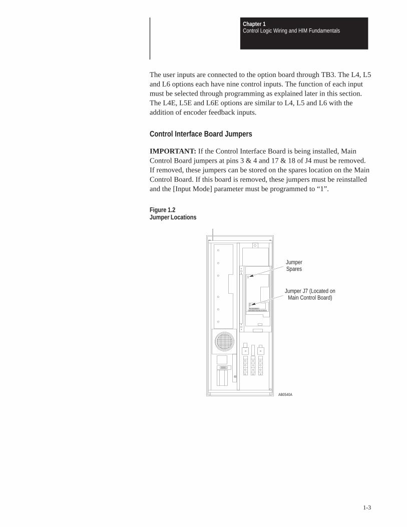
The user inputs are connected to the option board through TB3. The L4, L5and L6 options each have nine control inputs. The function of each inputmust be selected through programming as explained later in this section.The L4E, L5E and L6E options are similar to L4, L5 and L6 with theaddition of encoder feedback inputs.
Control Interface Board Jumpers
IMPORTANT: If the Control Interface Board is being installed, MainControl Board jumpers at pins 3 & 4 and 17 & 18 of J4 must be removed.If removed, these jumpers can be stored on the spares location on the MainControl Board. If this board is removed, these jumpers must be reinstalledand the [Input Mode] parameter must be programmed to “1”.
Figure 1.2Jumper Locations
AB0540A
JumperSpares
Jumper J7 (Located onMain Control Board)

Chapter 1Control Logic Wiring and HIM Fundamentals
1-4
Available Inputs
A variety of combinations made up of the following inputs are available.
Start Enable
Stop/Clear Fault Auxiliary
Reverse 2 Stop Mode Selects
Digital Potentiometer (MOP) Run Forward
2 Accel/Decel Rates Run Reverse
3 Speed Selects Local Control
The available combinations are shown in Figure 1.4. Programming the[Input Mode] parameter to one of the Input Mode numbers listed selectsthat combination of input functions.
IMPORTANT: The [Input Mode] parameter can be changed at any time.However, programming changes will not take affect until power has beencycled to the drive. When changing an input mode, it is important to notethat the corresponding inputs to TB3 may also change.
The programming options of the Control Interface Option allow you toselect an input combination to meet the needs of a specific installation.Appropriate selection of a combination may be done by using Table 1.A.First determine the type of start/stop/direction control desired. Then selectthe remaining control functions available. After selecting a group of InputModes use Figure 1.2 for specific mode selection. Record the selectedmode number below.
Selected Mode Number:
Local Programming For local programming and control information, refer to the 1336 PLUSUser Manual.

Chapter 1Control Logic Wiring and HIM Fundamentals
1-5
Table 1.AInput Mode Selection
Start/Stop Type Direction Control Communication CompatibilityMode(s)to Use
Stop & EnableOnly
None Control must be provided by HIM or Communication Option. 1
MomentaryPushbutton(3 Wire)
Maintained Switch(Open-Forward, Closed-Reverse)
Start/Stop – works in parallel with HIM and Communication Options.Direction Control will not work in parallel with HIM or CommunicationOptions. User must select direction control from either HIM andCommunication Options or TB3 input.
2 – 6
MomentaryPushbutton(3 Wire)
Momentary Pushbuttons(Forward and Reverse)
Start/Stop – works in parallel with HIM and Communication Options.Direction – works in parallel with HIM or Communication Options. 7 – 11
Maintained switches for combined run and directioncontrol (2 wire, Run Forward, Run Reverse)
Start/Stop – not compatible with HIM or Communication Options.Direction – not compatible with HIM or Communication Options.
12 – 16
The maximum and minimum wire sizes accepted by TB3 is 2.1 and0.30 mm2 (14 and 22 AWG). Maximum torque for all terminals is0.9 – 1.13 N-m (8 – 10 in.-lb).
Figure 1.3TB3 Terminal Designations L4E, L5E, and L6E Only
19 20 21 22 23 24 25 26 27 28 29 30 31 32 33 34 35 36
Inpu
t 1
Inpu
t 2 (S
top)
Com
mon
Inpu
t 3
Inpu
t 4
Inpu
t 5
Com
mon
Inpu
t 6
Inpu
t 7
Inpu
t 8
Com
mon
Enab
le
Enco
der B
Enco
der N
OT
A
Enco
der N
OT
B
Enco
der A
+12V
(200
mA
max
.)
Enco
der C
omm
on
AB0293A

Chapter 1Control Logic Wiring and HIM Fundamentals
1-6
Figure 1.4Input Mode Selection and Typical TB3 Connections
19
20
21
22
23
24
25
26
27
28
29
30
Status
Common
Status
Status
Status
Common
Status
Status
Status
Common
[Input Mode] 1Factory Default
19
20
21
22
23
24
25
26
27
28
29
30
Start
Common
Reverse
Common
Common
Jog StopType
2ndAccel
DigitalPot Up
Jog
Speed Speed 2ndDecel
DigitalPot Dn
Local
2 3 4 5 6
Mode
[Input Mode] 2 – 6
See Table 1.B. 1
Drive must be stopped to take Local Control.Control by all other adapters is disabled (except Stop).
2
These inputs must be present before drive will start. 3
User
Con
nect
ions
User
Con
nect
ions
AB0290B
Momentary
Maintained
AT
TE
NT
ION
:pr
oper
ly u
nles
s a
SC
AN
port
opt
ion
is c
onne
cted
to
the
driv
e. T
o as
sure
pro
per
JOG
fun
ctio
n, in
stal
l at
leas
t on
eof
the
fol
low
ing:
1201
-HA
P,
1201
-HA
1, 1
201-
HA
2, 1
336-
GM
1. A
pplie
sto
130
5 w
ith f
irmw
are
FR
N 2
.01
or e
arlie
r an
d 13
36
PLU
S w
ith L
angu
age
Mod
ule
1336
S-E
N f
irmw
are
FR
N1.
05 o
r ea
rlier
.The
JO
G f
unct
ion
will
not
ope
rate
Enable3
Enable3
Stop/Fault Reset3
Stop/Fault Reset3
Auxiliary3
Speed Select 21
Speed Select 11
Select 31 Select 31 Control2
Note: If this mode is selected, the status of allinputs can be read at the [Input Status] parameter.However, only “Stop/Fault Reset” and “Enable” willhave control function.
Three-Wire Control with Single-Source Reversing

Chapter 1Control Logic Wiring and HIM Fundamentals
1-7
Momentary
Maintained
Run Forward
Common
Run Reverse
Common
Common
Local StopType
2ndAccel
DigitalPot Up
Local
Speed Speed 2ndDecel
DigitalPot Dn
StopType
12 13 14 15 16Mode
[Input Mode] 12 – 16Two-Wire Control, Single-Source Control
19
20
21
22
23
24
25
26
27
28
29
30
Start
Common
Common
Common
Forward Forward DigitalPot Dn
Forward 2ndAccel
Jog Speed Speed DigitalPot Up
1stDecel
[Input Mode] 7 – 11Three-Wire Control with Multi-Source Reversing
Reverse Reverse DigitalPot Up
Reverse 1stAccel
7 8 9 10 11Mode
Speed Speed Speed DigitalPot Dn
2ndDecel
19
20
21
22
23
24
25
26
27
28
29
30
User
Con
nect
ions
User
Con
nect
ions
See Table 1.B. 1
Drive must be stopped to take Local Control.Control by all other adapters is disabled (except Stop).
2
AB0291B
These inputs must be present before drive will start. 3
AT
TE
NT
ION
:pr
oper
ly u
nles
s a
SC
AN
port
opt
ion
is c
onne
cted
to
the
driv
e. T
o as
sure
pro
per
JOG
fun
ctio
n, in
stal
l at
leas
t on
eof
the
fol
low
ing:
1201
-HA
P,
1201
-HA
1, 1
201-
HA
2, 1
336-
GM
1. A
pplie
sto
130
5 w
ith f
irmw
are
FR
N 2
.01
or e
arlie
r an
d 13
36
PLU
S w
ith L
angu
age
Mod
ule
1336
S-E
N f
irmw
are
FR
N1.
05 o
r ea
rlier
.The
JO
G f
unct
ion
will
not
ope
rate Stop/Fault Reset3
Auxiliary3
Speed Select 11
Enable3
Stop/Fault Reset3
Auxiliary3
Speed Select 21
Speed Select 11
Enable3
Select 21 Select 21 Select 21
Select 31 Select 31
Control2 Control2
Select 31 Select 31

Chapter 1Control Logic Wiring and HIM Fundamentals
1-8
The following table defines the input state of the Speed Select inputs foreach frequency source.
Table 1.BSpeed Select Input State vs. Frequency Source
Speed Select 3 Speed Select 2 Speed Select 1 Frequency Source
O O O [Freq Select 1]
O O X [Freq Select 2]
O X O [Preset Freq 2]
O X X [Preset Freq 3]
X O O [Preset Freq 4]
X O X [Preset Freq 5]
X X O [Preset Freq 6]
X X X [Preset Freq 7]
O = OpenX = Closed
Human InterfaceModule (HIM)
Description
When the drive mounted HIM is supplied, it will be connected as Adapter1 (refer to Figure 1.6). The HIM can be divided into two sections; DisplayPanel and Control Panel. The Display Panel provides a means ofprogramming the drive and viewing the various operating parameters. TheControl Panel allows different drive functions to be controlled. Refer to the1336 PLUS User Manual for HIM operation.
IMPORTANT: The operation of HIM functions depends upon driveparameter settings. Default parameter values allow full HIM functionality.

Chapter 1Control Logic Wiring and HIM Fundamentals
1-9
Figure 1.5Human Interface Module
AB0542A
Display Panel
Control Panel
Human Interface Module(HIM)
Figure 1.6Adapter Locations
AB0594A
CommunicationsPort RemoteHIM or PMT
Control InterfaceOption
(TB3 Adapter 0)
Drive MountedHIM (Adapter 1)Open Style Only
InternalCommunication
(Adapter 6)

Chapter 1Control Logic Wiring and HIM Fundamentals
1-10
Module Removal
ATTENTION: Some voltages present behind the drive front coverare at incoming line potential. To avoid an electric shock hazard,use extreme caution when removing/replacing the HIM.
For handheld operation, the module can be removed and located up to 10meters (33 feet) from the drive.
IMPORTANT: Power must be removed from the drive or Bit 1 of the[Logic Mask] parameter must be set to “0” to allow removal of the HIMmodule without causing a Communication Fault. Setting Bit 1 of the[Logic Mask] parameter to “0” allows HIM removal while power isapplied to the drive. Note that this also disables all HIM control functionsexcept Stop.
IMPORTANT: To remove the module:
1. Ensure that power has been removed or [Logic Mask] has been set to“0”.
2. Take the drive front cover off and simply slide the module down and outof its cradle. Remove cable from module.
3. Connect the appropriate cable between the HIM and theCommunications Port (Adaptor 2, 3, 4, or 5).
4. Reverse the above steps to replace the module. Apply power or resetBit 1 of the [Logic Mask] parameter to “1” to enable HIM control.
HIM Operation
When power is first applied to the drive, the HIM will cycle through aseries of displays. These displays will show drive ID and communicationstatus. Upon completion, the Status Display (refer to Figure 1.7) will beshown. This display shows the current status of the drive (i.e. Stopped,Running, etc.) or any faults that may be present (Not Enabled, etc.).Refer to the 1336 PLUS User Manual for HIM operation.
Figure 1.7Status Display
Stopped+0.00 Hz

ChapterChapter
2-1
Troubleshooting and Error Codes
Chapter Objectives This chapter helps you trace faults to field-replaceable components.
Troubleshooting To troubleshoot a 1336 PLUS Adjustable Frequency AC Drive, you need
Overview a Range DVM, DMM, or VOM with a range capacity of at least 1000 V.
IMPORTANT: All printed circuit boards are referenced to “common” perthe schematic diagrams.
ATTENTION: Power circuits are optically isolated from controldriver circuits. Power circuit components are floating with respectto ground. Use only approved methods of isolating test equipmentwhen making measurements in power circuits.
ATTENTION: Some printed circuit boards and drive componentsmay contain hazardous voltage levels. Remove power before youdisconnect or reconnect wires, and before you remove or replacefuses and circuit boards. Verify bus voltage by measuring thevoltage between the Negative Capacitor Bus and both ends of allthree 350 amp fuses. An open fuse does not show voltage acrossboth ends of the fuse. Failure to measure voltage at both ends of thefuses may result in death or serious injury. Refer to Figure 3.5. Donot attempt to service the drive until the bus voltage has dischargedto zero volts.
ATTENTION: Potentially fatal voltages may result from improperusage of oscilloscope and other test equipment. The oscilloscopechassis may be at a potentially fatal voltage if not properlygrounded. We do not recommend use of an oscilloscope to directlymeasure high voltages. Use an isolated measuring device with ahigh voltage probe. Contact Allen-Bradley for recommendations.

Chapter 2Troubleshooting and Error Codes
2-2
ATTENTION: To guard against equipment damage whentroubleshooting the drive, always check the following beforeissuing a Start command:
• Set the Speed Reference to minimum.• Select the proper motor-rotation direction.• Disconnect the motor from its mechanical load.
ATTENTION: This assembly contains parts and sub-assembliesthat are sensitive to electrostatic discharge. Static controlprecautions are required when servicing this assembly. Componentdamage may result if you ignore electrostatic discharge controlprocedures. If you are not familiar with static control procedures,reference Allen-Bradley Publication 8000–4.5.2, Guarding AgainstElectrostatic Discharge, or any other applicable ESD protectionhandbook.
Electrostatic Discharge Electrostatic Discharge generated by static electricity can damage the
Precautions complimentary metallic oxide semiconductor devices on various driveboards. It is recommended that you perform these procedures to guardagainst this type of damage when circuit boards are removed or installed:
Wear a wrist type grounding strap that is grounded to the chassis.
Attach the wrist strap before removing the new circuit board from theconductive packet.
Remove boards from the drive and immediately insert them into theirconductive packets.

Chapter 2Troubleshooting and Error Codes
2-3
Fault Descriptions
Fault Display
The LCD display is used to indicate a fault by showing a brief textstatement relating to the fault (refer to figure below). The fault will bedisplayed until a drive reset is initiated. Refer to Table 2.A for a listing anddescription of the various faults. Table 2.B provides a listing of faults bynumber.
Overvolt FaultF 5
IMPORTANT: Before clearing a fault, refer to the Fault Descriptionstable and Diagnostic Procedures by Symptom flowcharts in this chapter toisolate and correct faults.
To help differentiate parameter names and display text from other text inthis manual, the following conventions will be used:Parameter Names will appear in [brackets]Display Text will appear in “quotes”
Contact Description
During normal operating conditions (no faults present, drive running) theCR3 fault contacts at TB2–13 & 14 are open, and the contacts at TB2–14& 15 are closed. When a fault occurs, the state of these contacts changes.

Chapter 2Troubleshooting and Error Codes
2-4
Table 2.A1336 PLUS Fault Descriptions
Name & Fault # Description Action
Adptr Freq Err65
The SCANport adapter that was the selected frequencyreference sent a frequency greater than 32767 to thedrive.
Correct the problem that is causing the SCANportadapter to send the illegal frequency reference to thedrive.
Auxiliary Fault02
The auxiliary input interlock is open. If Control Interface option is installed, check connec-tions at TB3-24. If option is not installed, set [InputMode] to “1”.
BGND 10ms Over51
Microprocessor loop fault. Occurs if the 10msbackground task hasn’t been run in 15 ms.
Replace Main Control Board or complete drive asrequired.
Blwn Fuse Flt58
If the difference between the commanded voltage andthe measured voltage is greater than 1/8 of ratedvoltage for 0.5 seconds, then a fault will be issuedindicating that the bus fuse in 30 kW (40 HP) and updrives has blown.
Locate cause, replace Fuse.
Diag C Lim Flt36
The drive output current has exceeded the hardwarecurrent limit and the [Cur Lim Trip En] parameter wasenabled.
Check programming of [Cur Lim Trip En] parameter.Check for excess load, improper DC boost setting, DCbrake volts set too high or other causes of excesscurrent.
Drive Fault Reset22
Power-up has been attempted with an Open Stopcontact or Closed Start contact.
Check/verify wiring and contact operation.
Drive –> HIM Error 1 – The checksum read from the EEPROM doesnot match the checksum calculated from the EEPROMdata.
Repeat operation. Replace HIM.
EE Init Read53
1. Gate Driver Board replacement (requires re-initialization).
2. Trouble reading EEPROM during initialization.
1. Reset to factory defaults & cycle input power.2. Check all connections to the Power/Driver Board.
Replace the board or complete drive as needed.
EE Init Value54
Stored parameter value is out of range on initialization. 1. Reset to factory defaults & cycle input power.2. Check all connections to the Power/Driver Board.
Replace the board or complete drive as needed.
EEprom Checksum66
The checksum read from the EEPROM does not matchthe checksum calculated from the EEPROM data.
1. Reset to factory defaults & cycle input power.2. Check all wire and cable connections to the
Power/Driver Board. Replace the Power/DriverBoard or complete drive as required.
EEprom Fault32
EEPROM is being programmed and will not write a newvalue.
Check all wire and cable connections to the MainControl Board. Replace Main Control Board or completedrive as required.
FGND 10ms Over52
Microprocessor loop fault. Occurs if a 10ms interrupt ispending before the current interrupt is complete.
Replace Main Control Board or complete drive asrequired.
Ground Fault13
A current path to earth ground in excess of 100A hasbeen detected at one or more of the drive outputterminals. NOTE: If ground current exceeds 220% ofdrive rated current, “Overcurrent Flt” may occur insteadof Ground Fault.
Check the motor and external wiring to the drive outputterminals for a grounded condition.
Chapter 2Troubleshooting and Error Codes
2-5
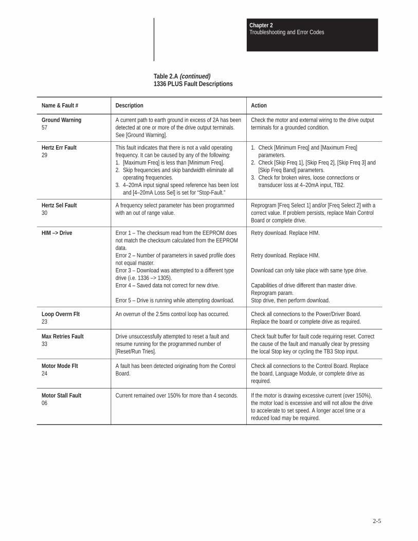
Table 2.A (continued)1336 PLUS Fault Descriptions
Name & Fault # Description Action
Ground Warning57
A current path to earth ground in excess of 2A has beendetected at one or more of the drive output terminals.See [Ground Warning].
Check the motor and external wiring to the drive outputterminals for a grounded condition.
Hertz Err Fault29
This fault indicates that there is not a valid operatingfrequency. It can be caused by any of the following:1. [Maximum Freq] is less than [Minimum Freq].2. Skip frequencies and skip bandwidth eliminate all
operating frequencies.3. 4–20mA input signal speed reference has been lost
and [4–20mA Loss Sel] is set for “Stop-Fault.”
1. Check [Minimum Freq] and [Maximum Freq]parameters.
2. Check [Skip Freq 1], [Skip Freq 2], [Skip Freq 3] and[Skip Freq Band] parameters.
3. Check for broken wires, loose connections ortransducer loss at 4–20mA input, TB2.
Hertz Sel Fault30
A frequency select parameter has been programmedwith an out of range value.
Reprogram [Freq Select 1] and/or [Freq Select 2] with acorrect value. If problem persists, replace Main ControlBoard or complete drive.
HIM –> Drive Error 1 – The checksum read from the EEPROM doesnot match the checksum calculated from the EEPROMdata.Error 2 – Number of parameters in saved profile doesnot equal master.Error 3 – Download was attempted to a different typedrive (i.e. 1336 –> 1305).Error 4 – Saved data not correct for new drive.
Error 5 – Drive is running while attempting download.
Retry download. Replace HIM.
Retry download. Replace HIM.
Download can only take place with same type drive.
Capabilities of drive different than master drive.Reprogram param.Stop drive, then perform download.
Loop Overrn Flt23
An overrun of the 2.5ms control loop has occurred. Check all connections to the Power/Driver Board.Replace the board or complete drive as required.
Max Retries Fault33
Drive unsuccessfully attempted to reset a fault andresume running for the programmed number of[Reset/Run Tries].
Check fault buffer for fault code requiring reset. Correctthe cause of the fault and manually clear by pressingthe local Stop key or cycling the TB3 Stop input.
Motor Mode Flt24
A fault has been detected originating from the ControlBoard.
Check all connections to the Control Board. Replacethe board, Language Module, or complete drive asrequired.
Motor Stall Fault06
Current remained over 150% for more than 4 seconds. If the motor is drawing excessive current (over 150%),the motor load is excessive and will not allow the driveto accelerate to set speed. A longer accel time or areduced load may be required.
Chapter 2Troubleshooting and Error Codes
2-6
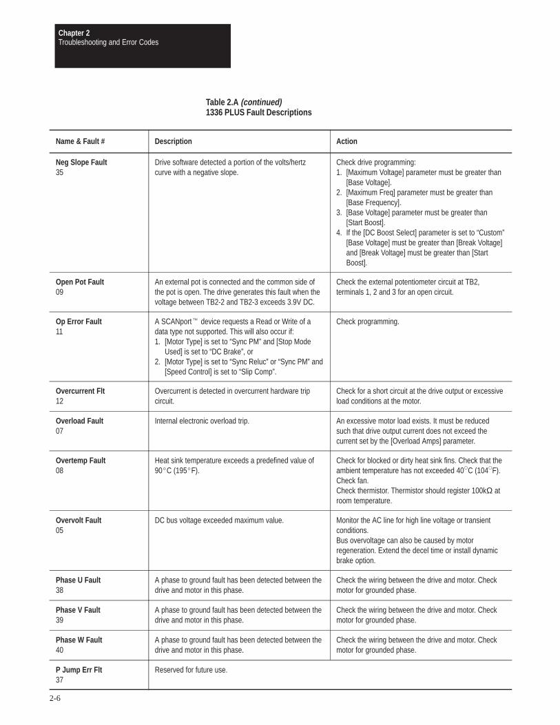
Table 2.A (continued)1336 PLUS Fault Descriptions
Name & Fault # Description Action
Neg Slope Fault35
Drive software detected a portion of the volts/hertzcurve with a negative slope.
Check drive programming:1. [Maximum Voltage] parameter must be greater than
[Base Voltage].2. [Maximum Freq] parameter must be greater than
[Base Frequency].3. [Base Voltage] parameter must be greater than
[Start Boost].4. If the [DC Boost Select] parameter is set to “Custom”
[Base Voltage] must be greater than [Break Voltage]and [Break Voltage] must be greater than [StartBoost].
Open Pot Fault09
An external pot is connected and the common side ofthe pot is open. The drive generates this fault when thevoltage between TB2-2 and TB2-3 exceeds 3.9V DC.
Check the external potentiometer circuit at TB2,terminals 1, 2 and 3 for an open circuit.
Op Error Fault11
A SCANport device requests a Read or Write of adata type not supported. This will also occur if:1. [Motor Type] is set to “Sync PM” and [Stop Mode
Used] is set to “DC Brake”, or2. [Motor Type] is set to “Sync Reluc” or “Sync PM” and
[Speed Control] is set to “Slip Comp”.
Check programming.
Overcurrent Flt12
Overcurrent is detected in overcurrent hardware tripcircuit.
Check for a short circuit at the drive output or excessiveload conditions at the motor.
Overload Fault07
Internal electronic overload trip. An excessive motor load exists. It must be reducedsuch that drive output current does not exceed thecurrent set by the [Overload Amps] parameter.
Overtemp Fault08
Heat sink temperature exceeds a predefined value of90C (195F).
Check for blocked or dirty heat sink fins. Check that theambient temperature has not exceeded 40C (104F).Check fan.Check thermistor. Thermistor should register 100kΩ atroom temperature.
Overvolt Fault05
DC bus voltage exceeded maximum value. Monitor the AC line for high line voltage or transientconditions.Bus overvoltage can also be caused by motorregeneration. Extend the decel time or install dynamicbrake option.
Phase U Fault38
A phase to ground fault has been detected between thedrive and motor in this phase.
Check the wiring between the drive and motor. Checkmotor for grounded phase.
Phase V Fault39
A phase to ground fault has been detected between thedrive and motor in this phase.
Check the wiring between the drive and motor. Checkmotor for grounded phase.
Phase W Fault40
A phase to ground fault has been detected between thedrive and motor in this phase.
Check the wiring between the drive and motor. Checkmotor for grounded phase.
P Jump Err Flt37
Reserved for future use.

Chapter 2Troubleshooting and Error Codes
2-7
Table 2.A (continued)1336 PLUS Fault Descriptions
Name & Fault # Description Action
Pole Calc Fault50
Generated if the calculated value of [Motor Poles] isless than 2 or greater than 32.
Check [Motor NP RPM] and [Motor NP Hertz]programming.
Power Loss Fault03
DC bus voltage remained below 85% of nominal forlonger than 0.500ms. [Line Loss Fault] parameter is setto “enabled.”
Monitor the incoming AC line for low voltage or linepower interruption.
Power Mode Fault26
The internal power mode variable received an incorrectvalue.
Check all connections to the Control Board. Replacethe board, Language Module, or complete drive asrequired.
Power Overload64
The drive rating of 150% for 1 minute has beenexceeded.
Reduce load.
Power Test Flt46
The internal power mode variable received an incorrectvalue.
Check all connections to the Power/Driver Board.Replace the board or complete drive as required.
Precharge Fault19
Occurs if precharge device is open 20ms after the endof a line loss condition or if the bus charging alarmremains on for 20 seconds (precharge did notcomplete).
All larger frames – Check the precharge circuit. Replacethe input SCRs, SCR Firing Board, Power Driver Boardor complete drive as needed.
Precharge Open56
The precharge circuit was commanded to close, butwas detected to be open.
All larger frames – Check the precharge circuit. Replacethe input SCRs, SCR Firing Board, Power Driver Boardor complete drive as needed.
Reprogram Fault48
The drive was commanded to write default values toEEPROM.
1. Clear the fault or cycle power to the drive.2. Program the drive parameters as needed.Important: If [Input Mode] has been changed from itsoriginal value, power must be cycled before the newvalue will take affect.
ROM or RAM Flt68
Internal power-up ROM or RAM tests have notexecuted properly.
Check Language Module. Replace Control Board orcomplete drive as required.
Run Boost Fault34
An attempt has been made to set the [Run Boost]parameter to a value greater than the [Start Boost]parameter.
Verify that parameter has been programmed correctly.
Serial Fault10
A SCANport adapter has been disconnected and the[Logic Mask] bit for that adapter is set to “1.”
1. If no adapter was intentionally disconnected, checkwiring to the SCANport adapters. Replace wiring,SCANport expander, SCANport adapters, MainControl Board or complete drive as required.
2. If an adapter was intentionally disconnected and the[Logic Mask] bit for that adapter is set to “1”, thisfault will occur. To guard against this fault occurring,set the [Logic Mask] bit for the adapter to “0.”
Shear Pin Fault63
Programmed [Current Limit] amps has been exceededand [Shear Pin Fault] is enabled.
Check load requirements and [Current Limit] setting.

Chapter 2Troubleshooting and Error Codes
2-8
Table 2.A (continued)1336 PLUS Fault Descriptions
Name & Fault # Description Action
Temp Sense Open55
Heat sink thermistor is open or malfunctioning. Check thermistor and connections.
Undervolt Fault04
DC Bus voltage fell below the minimum value (388V DCat 460V AC input). [Line Loss Fault] and [Low BusFault] set to “enabled.”
Monitor the incoming AC line for low voltage or linepower interruption.
UV Short Fault41
Excessive current has been detected between thesetwo output terminals.
Check the motor and external wiring to the drive outputterminals for a shorted condition.
UW Short Fault42
Excessive current has been detected between thesetwo output terminals.
Check the motor and external wiring to the drive outputterminals for a shorted condition.
VW Short Fault43
Excessive current has been detected between thesetwo output terminals.
Check the motor and external wiring to the drive outputterminals for a shorted condition.
Xsistr Desat Flt47
One or more of the output transistors were operating inthe active region instead of desaturation. This can becaused by excessive transistor current or insufficientbase drive voltage.
Check for damaged output transistors. Replace outputtransistors, Power Driver Board or complete drive asneeded.

Chapter 2Troubleshooting and Error Codes
2-9
Table 2.BFault Code Cross Reference
Fault # Display Name Reset/Run
02 Auxiliary Fault Yes
03 Power Loss Fault Yes
04 Undervolt Fault Yes
05 Overvolt Fault Yes
06 Motor Stall Fault Yes
07 Overload Fault Yes
08 Overtemp Fault Yes
09 Open Pot Fault No
10 Serial Fault No
11 Op Error Fault No
12 Overcurrent Flt Yes
13 Ground Fault No
19 Precharge Fault No
22 Drive Fault Reset Yes
23 Loop Overrn Flt Yes
24 Motor Mode Flt Yes
26 Power Mode Fault Yes
28 Timeout Fault No
29 Hertz Err Fault No
30 Hertz Set Fault No
31 Timeout Fault No
32 EEprom Fault No
33 Max Retries Fault No
34 Run Boost Fault No
35 Neg Slope Fault No

Chapter 2Troubleshooting and Error Codes
2-10
Table 2.B (continued)Fault Code Cross Reference
Fault # Display Name Reset/Run
36 Diag C Lim Flt No
37 P Jump Err Flt No
38 Phase U Fault No
39 Phase V Fault No
40 Phase W Fault No
41 UV Short Fault No
42 UW Short Fault No
43 VW Short Fault No
46 Power Test Flt No
47 Xsistr Desat Flt No
48 Reprogram Fault No
50 Pole Calc Fault No
51 BGND 10ms Over Yes
52 FGND 10ms Over Yes
53 EE Init Read No
54 EE Init Value No
55 Temp Sense Open No
56 Precharge Open No
57 Ground Warning No
58 Blwn Fuse Flt No
63 Shear Pin Fault No
64 Power Overload No
65 Adptr Freq Err No
66 EEprom Checksum No
68 ROM or RAM Flt No

Chapter 2Troubleshooting and Error Codes
2-11
Diagnostic Procedures These charts list drive symptoms, symptom descriptions, and
by Symptom recommended actions to remedy the symptoms.
Drive Will Not Start
AB0416B
Yes
Drive will not start.
HIM displays“Auxiliary Fault”?
No
Display on HIM?
Yes
NoRefer to “No Display”.
Drive equippedwith L Option?
Yes Auxiliary Input True? Correct AuxiliaryCircuit and clear fault.
Program [InputMode] to “1” and
cycle input power.
No
Replace L Option orMain Control Board.
Yes
YesHIM displays“Not Enabled”?
No
Drive equippedwith L Option?
Yes Enable Input True? No Correct Enable Circuit.
Add a jumper to J7between pins 3 and 4
or replace Main ControlBoard as needed.
No
Yes
YesHIM displaysfault message?
Follow instructionsgiven in Table 2.A.
NoHIM displays“Stopped”?
Drive running atzero Hertz?
No
Yes
Yes Refer to: “DriveStays at Zero Hertz
When Started”.
NoAre any bits in[Stop Owner] set to
“1”?
Find and correct sourceof STOP command.
No
NoDoes [Start Owner]show a bit set to “1”
when STARTcommanded?
Correct Start Inputcircuit or replace
Main Control Boardas needed.
Yes
Drive Starts?
Yes
No Replace MainControl Board.
End of troubleshooting.
No

Chapter 2Troubleshooting and Error Codes
2-12
No Display
AB0417A
No
No HIM display.
Is the drive’s fanrunning?
Yes
Is the HIM backlight lit?Yes
No
Replace the HIM,Main Control Board,
Language Module, orcomplete drive as
needed.
Voltage present atTB1-R, -S, -T?
No Restore incomingpower to drive.
HIM connectedproperly?
Yes
Replace HIM, MainControl Board, orGate Driver Board
as needed.
NoRe-connect HIM. Is the fuse blown
on the GateDriver Board?
Replace the fuse,Gate Driver Board,
or complete drive asneeded.
Yes
No
DC bus voltagepresent?
Replace GateDriver Board.
Yes
No
Replace the DiodeBridge and any other
damaged components.
Yes

Chapter 2Troubleshooting and Error Codes
2-13
Drive Will Not Jog
Local Human Interface Module used to control drive.
JOG is not active if a START command is present. START commandalways overrides a JOG command.
AB0418A
Drive will not Jog.
Is drive running?Yes
No
Drive must bestopped before
attempting to Jog.
Will drive run ifcommanded to Start?
No Refer to “Drive WillNot Start”.
Does a [Jog Owner]bit go to 1 when Jog
is commanded?
Yes
No Is the [Jog Mask] bitfor the adapter being
used set to 1?
Yes Is the Jog Input truewhen Jog is
commanded?
Yes Replace the Adapter,L Option, or Main
Control Board.
Set the [Jog Mask]bit for the adapterbeing used to 1.
External wiring problem.
No NoYes
HIM displays“Stopped” when Jog
is commanded?
No Drive running atincorrect frequency?
No Replace MainControl Board.
Yes
Is a [Stop Owner] bitset to 1?
Yes Find and correct thesource of the Stop
command.
No
Is Logic Mask bit setto 0?
Reprogram [JogFrequency].
Yes
No
Replace MainControl Board
Yes Change Logic Maskbit to 1.

Chapter 2Troubleshooting and Error Codes
2-14
Drive Stays at Zero Hertz When Started
IMPORTANT: [Command Frequency] parameter in the Metering Groupcan be checked using the HIM.
AB0419A
Drive stays at ZeroHertz when Started.
No[Drive Status]Running Bit(Bit 1) = 1?
Refer to “DriveWill Not Start”.
Yes
HIM displays “At Speed”or [Drive Status] At
Speed Bit (Bit 8) = 1?
No HIM displays“Accelerating” or
[Drive Status] AccelBit (Bit 4) = 1?
Yes Are [Accel Time 1] or[Accel Time 2] set to
very long times?
Yes Set [Accel Time 1] or[Accel Time 2] to correct
application values.
Yes
[Command Freq]greater than zero?
Yes Replace MainControl Board, Gate
Driver Board, ordrive as needed.
No [Drive Alarm] MotorLimit or Regen LimitBits (Bits 2 & 3) = 1?
Yes Correct excessivemotor load condition.
No No
No
Is [Freq Source]correct?
No Is [Input Mode] setto a mode with L
Option TB3 SpeedSelect inputs?
No SCANport adapter has selectedan incorrect reference. Correct
the problem with, or replace, theSCANport adapter.
Yes
Is the frequencyreference input to the
drive at zero?
Yes Correct problem withfrequency reference.
Replace Main ControlBoard or completedrive as needed.
No
Check state of SpeedSelect inputs on TB3.Check programmingof [Reference Mask]
and [Input Mode].
Yes

Chapter 2Troubleshooting and Error Codes
2-15
Drive Goes to Max Frequency
IMPORTANT: [Command Frequency] parameter in the Metering Groupcan be checked using the HIM.
Does the meteringparameter for the
frequency referenceequal [Maximum Freq]?
AB0420B
Drive goes to[Maximum Freq].
YesIs [Command Freq] =[Maximum Freq]?
No
[Freq Source]correct?
Yes
NoIs Scanport Adapter orL Option set to selectthe correct reference?
Yes
Replace Main ControlBoard.
Skip Frequencyfunction interfering
with reference?
Yes Reprogram the SkipFrequency function.
Correct the SpeedSelect inputs.
No
No
[Freq source] =Adapter 1–6?
Yes Replace the Adapterproviding the reference.
No
[Freq source] =Preset 1–7?
Yes Is the Preset usedprogrammed to
[Maximum Freq]?
Yes Reprogram to correctvalue.
No
No
No
Yes
Input signal at TB2normal?
Yes[Analog Invert] correct?
No Reprogram[Analog Invert].
No
Correct input signalproblem.
Yes
Drive is correctlyfollowing Freq
Reference
Clearing Faults After correcting a fault, you can clear a fault from the drive in one of threeways:
1. Cycle the input power to the drive.
2. Press the Stop button. This works only if [Fault Clear Mode] is set to“Enabled”.
3. Issue a reset command from a serial device.

Chapter 2Troubleshooting and Error Codes
2-16
This Page Intentionally Left Blank

Chapter
3-1
Disassembly and Access Procedures
Chapter Objectives This chapter describes general disassembly procedures required to accessinternal drive components.
Disassembly and Access Overview
ATTENTION: Some printed circuit boards and drive componentsmay contain hazardous voltage levels. Remove and lock out powerbefore you disconnect or reconnect wires, and before you removeor replace fuses and circuit boards. Verify bus voltage bymeasuring the voltage between the Negative Capacitor Bus andboth ends of all three 350 amp fuses. An open fuse does not showvoltage across both ends of the fuse. Failure to measure voltage atboth ends of the fuses may result in death or serious injury. Refer toFigure 3.5. Do not attempt to service the drive until the bus voltagehas discharged to zero volts.
ATTENTION: Servicing energized industrial control equipmentcan be hazardous. Electrical shock, burns, or unintentionalactuation of controlled industrial equipment may cause death orserious injury. Follow the safety-related practices of NFPA 70E,Electrical Safety for Employee Workplaces, when working on ornear energized equipment. Do not work alone on energizedequipment.
Electrostatic Discharge Precautions
ATTENTION: This assembly contains parts and sub-assembliesthat are sensitive to electrostatic discharge. Static controlprecautions are required when servicing this assembly. Componentdamage may result if you ignore electrostatic discharge controlprocedures. If you are not familiar with static control procedures,reference Allen-Bradley Publication 8000–4.5.2, Guarding AgainstElectrostatic Discharge, or any other applicable ESD protectionhandbook.
Chapter 3Disassembly and Access Procedures
3-2
Electrostatic discharge generated by static electricity can damage thecomplimentary metallic oxide semiconductor devices on various driveboards. It is recommended that you perform these procedures to guardagainst this type of damage when circuit boards are removed or installed:
Wear a wrist-type grounding strap that is grounded to the chassis.
Attach the wrist strap before removing the new circuit board from theconductive packet.
Remove boards from the drive and immediately insert them into theirconductive packets.
Tools
You need the following tools to disassemble and assemble the drive: Pliers
Phillips screwdrivers (small, medium, and large)
Standard screwdrivers (small, medium, and large)
Metric socket set up to 19 mm
Torque wrench to 34 N-m or 280 in.-lbs
Torque screwdriver to 10 N-m or 80 in.-lbs
Nylon tie wraps
Chapter 3Disassembly and Access Procedures
3-3
Fastener Torque Specifications
Torque Sequence
When mounting components to a drive’s heat sink, component-fastenertorque sequences and tolerances are crucial to component-to-heat sink heatdissipation.
ATTENTION: Component can be damaged if temporarytightening procedure is not performed to specification.
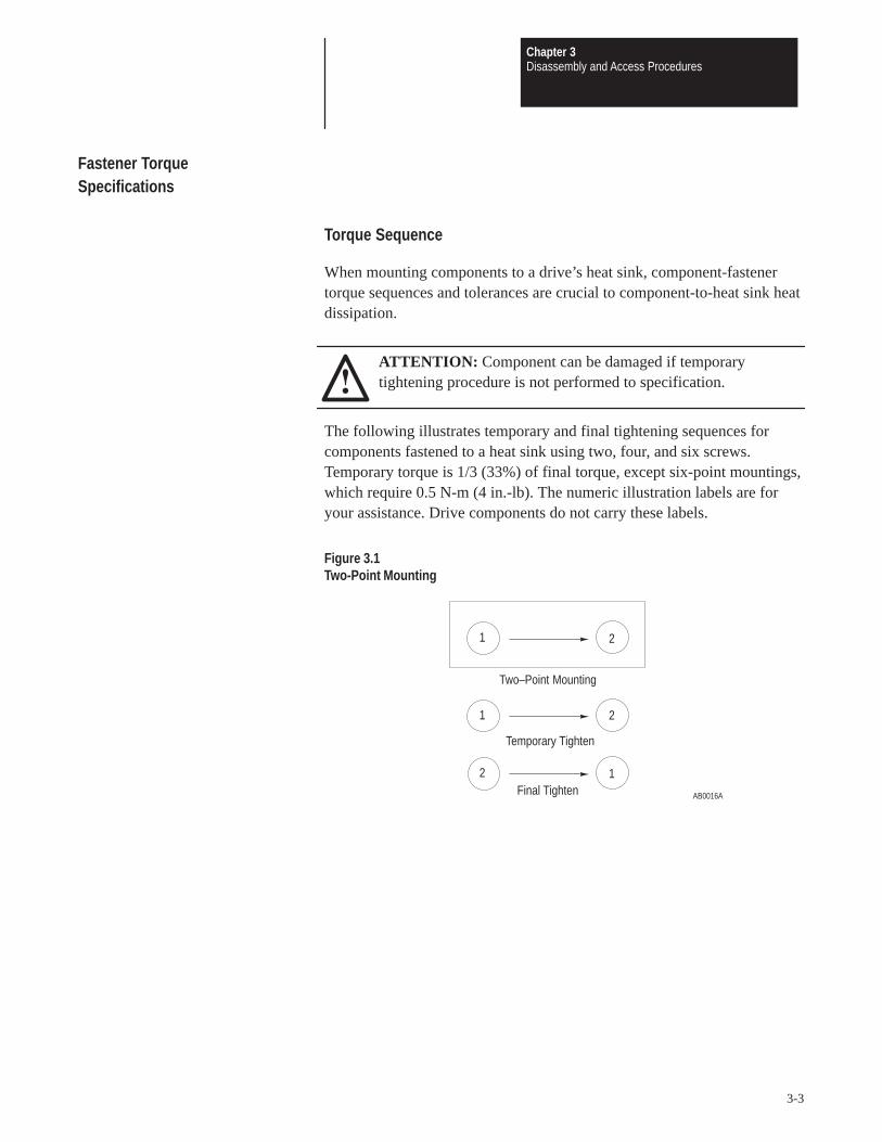
The following illustrates temporary and final tightening sequences forcomponents fastened to a heat sink using two, four, and six screws.Temporary torque is 1/3 (33%) of final torque, except six-point mountings,which require 0.5 N-m (4 in.-lb). The numeric illustration labels are foryour assistance. Drive components do not carry these labels.
Figure 3.1Two-Point Mounting
21
AB0016A
12
21
Temporary Tighten
Final Tighten
Two–Point Mounting

Chapter 3Disassembly and Access Procedures
3-4
Figure 3.2Four-Point Mounting
AB0017A
1
2
3
4
1 32 4
4 123
Temporary Tighten
Final Tighten
Four–Point Mounting
Figure 3.3Six-Point Mounting
AB0624B
6
3
2
1
4
5
Note: Do not exceed 0.4 Newton-meters (3 in.-lb) on initial torque or 3.8Newton-meters (32 in.-lb) final torque of all six screws.
Torque Specifications
The following table lists fastener locations by component, how thefasteners are used, and torque specifications. Refer to Torque Sequence inthis chapter for fastening two-point, four-point and six-point components tothe heat sink.

Chapter 3Disassembly and Access Procedures
3-5
Table 3.AFastener Torque Specifications
Component Fastener Application Torquein.-lb
TorqueN-m
Fan Motor Motor to Fan Cover Assembly 14 2
Fan Transformer Transformer to chassis 75 9
Fan Capacitor Capacitor to chassis Hand-tighten
MOV Surge Suppressor MOV to chassis 18 2
Snubber Resistor Resistor to heat sink 26 3
Snubber Bracket Bracket to Power Module Laminated Bus 90 11
Snubber Board Board to Brackets 18 2
Snubber Board Board to Input Rectifier Bracket 18 2
Volt Sharing Resistor Resistor to heat sink 26 3
Volt Sharing Resistor Wires to Capacitor Bus Bar Assembly 50 6
Thermistor Thermistor to heat sink 14 2
Bus Capacitor Holder Holder to Bus Capacitors 26 3
Capacitor Bus Bar Assembly Assembly to Bus Capacitors 50 6
Power Module Gate Interface Board Board to Power Modules 18 2
Power Module Bus Bar Bus Bar to Power Modules 90 11
Power Module Module to heat sink Refer to Figure 3.3
Input Rectifier (SCR) Rectifier to heat sink
Transitional Bus Bar Assembly Assembly to Power Module Bus Bar Assembly 80 9
Bus Fuse F1 – F3 Fuse to Transitional Bus Bar Assembly 240 28
DC Bus Inductor L1 Inductor to chassis 75 9
Bus Bar Cable AdaptorAdaptor to Transitional Bus Bar Assembly and DC Bus Inductor, right side of Motor Flex Bus
75 9
Converter Bus and Motor Bus Bars All connections 240 28
Wires (PE) Wires to Ground Stud 175 21
Wire (TE) Wire on Main Control Board Mounting Plate 26 3
Wires Wires to TB2 7 0.8
Wires Wires to TB3 8 – 10 09 – 1.1
Power Cables Cables to terminals 240 28
Main Control, Gate Driver, PrechargeBoard Mounting Plates
Plates to chassis 26 3
Heat Sink Guard Guard to chassis 18 2
T-Bar Mounting Bolt T-Bar to Main Frame 240 28.8
Capacitor Mounting Bolt Capacitor Bank Assembly to Main Frame 240 28.8
Inverter Housing Assembly Lock-DownBolt
Inverter Housing Assembly to Main Frame 240 28.8
Wheel Chock Fasteners Wheel Chocks to tracks 75 9
Ground Cable Bolts Ground Cables from both assemblies to Main Frame 75 9
Refer to the gauge on the clamp, which indicates pounds of force. The reading should be 400 lbs.

Chapter 3Disassembly and Access Procedures
3-6
Disassembly and Access Procedures
Opening the Drive Enclosure
Figure 3.4Drive Enclosure
AB0595A
PC BoardMounting Frame

Chapter 3Disassembly and Access Procedures
3-7
Opening
ATTENTION: Disconnect and lock out power from the drivebefore disassembling the drive. Failure to disconnect power mayresult in death or serious injury. Verify bus voltage by measuringthe voltage between the Negative Capacitor Bus and both ends ofall three 350 amp fuses. An open fuse does not show voltage acrossboth ends of the fuse. Failure to measure voltage at both ends of thefuses may result in death or serious injury. Refer to Figure 3.5. Donot attempt to service the drive until the bus voltage has dischargedto zero volts.
ATTENTION: Wear a wrist-type grounding strap when servicing1336 PLUS Drives. Failure to protect drive components againstESD may damage drive components. Refer to ElectrostaticDischarge Precautions at the beginning of this chapter.
1. Remove power from the drive.
2. Turn the enclosure door latches 1/4 turn counterclockwise to open theenclosure door.
3. Turn the latches, located on the left side of the PC Board Mountingframe, to open the PC Board Mounting Frame. Refer to Figure 3.6.
4. Check for zero volts between +DC and –DC. Refer to Figure 3.5.

Chapter 3Disassembly and Access Procedures
3-8
Figure 3.5DC Voltage Check
AB0637B
–DC (NegativeCapacitor Bus)
+DC
Check All ThreeBus Fuses
ATTENTION: A blown fuse can create a hazard of shock whichmay result in death or serious injury. Check voltage between thebus bar and both ends of all three fuses.
5. Check for the absence of control voltage at the points marked on theMain Control Board.
Closing
Close the Drive Enclosure in reverse order of opening.
ATTENTION: Replace all guards before applying power to thedrive. Failure to replace guards may result in death or seriousinjury.

Chapter 3Disassembly and Access Procedures
3-9
Removing the Control Interface Board
Figure 3.6Control Interface Board
AB0596A
Control InterfaceBoard
Terminal StripTB3
Main ControlBoard
Removal
ATTENTION: Disconnect and lock out power from the drivebefore disassembling the drive. Failure to disconnect power mayresult in death or serious injury. Verify bus voltage by measuringthe voltage between the Negative Capacitor Bus and both ends ofall three 350 amp fuses. An open fuse does not show voltage acrossboth ends of the fuse. Failure to measure voltage at both ends of thefuses may result in death or serious injury. Refer to Figure 3.5. Donot attempt to service the drive until the bus voltage has dischargedto zero volts.

Chapter 3Disassembly and Access Procedures
3-10
ATTENTION: Wear a wrist-type grounding strap when servicing1336 PLUS Drives. Failure to protect drive components againstESD may damage drive components. Refer to ElectrostaticDischarge Precautions at the beginning of this chapter.
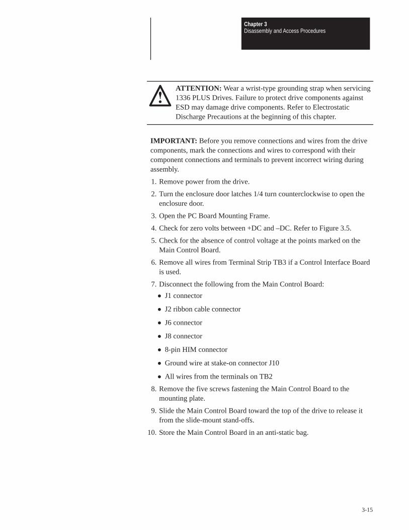
IMPORTANT: Before you remove connections and wires from the drivecomponents, mark the connections and wires to correspond with theircomponent connections and terminals to prevent incorrect wiring duringassembly.
1. Remove power from the drive.
2. Turn the enclosure door latches 1/4 turn counterclockwise to open theenclosure door.
3. Open the PC Board Mounting Frame.
4. Check for zero volts between +DC and –DC. Refer to Figure 3.5.
5. Check for the absence of control voltage at the points marked on theMain Control Board.
6. Remove all wires from Control Interface Board TB3.
7. Loosen the two captive screws fastening the Control Interface Board tothe Main Control Board.
8. Grip the right and left sides of the Control Interface Board and pull theboard straight out from the Main Control Board.
Installation
Install the Control Interface Board in reverse order of removal.
ATTENTION: Replace all guards before applying power to thedrive. Failure to replace guards may result in death or seriousinjury.

Chapter 3Disassembly and Access Procedures
3-11
Removing the Main Control Board Mounting Plate
Figure 3.7Main Control Board Mounting Plate
AB0597A
Main ControlBoard
ConnectorJ1
ConnectorJ6
ConnectorJ8
TerminalStrip TB2
MountingPlate
ConnectorJ2
Terminal StripTB3
TerminalStrip TE
8-Pin HIMConnector

Chapter 3Disassembly and Access Procedures
3-12
Removal
ATTENTION: Disconnect and lock out power from the drivebefore disassembling the drive. Failure to disconnect power mayresult in death or serious injury. Verify bus voltage by measuringthe voltage between the Negative Capacitor Bus and both ends ofall three 350 amp fuses. An open fuse does not show voltage acrossboth ends of the fuse. Failure to measure voltage at both ends of thefuses may result in death or serious injury. Refer to Figure 3.5. Donot attempt to service the drive until the bus voltage has dischargedto zero volts.
ATTENTION: Wear a wrist-type grounding strap when servicing1336 PLUS Drives. Failure to protect drive components againstESD may damage drive components. Refer to ElectrostaticDischarge Precautions at the beginning of this chapter.
IMPORTANT: Before you remove connections and wires from the drivecomponents, mark the connections and wires to correspond with theircomponent connections and terminals to prevent incorrect wiring duringassembly.
1. Remove power from the drive.
2. Turn the enclosure door latches 1/4 turn counterclockwise to open theenclosure door.
3. Open the PC Board Mounting Frame.
4. Check for zero volts between +DC and –DC. Refer to Figure 3.5.
5. Check for the absence of control voltage at the points marked on theMain Control Board.
6. Disconnect the following from the Main Control Board:
J1 connector
J2 ribbon cable connector
J8 connector
8-pin HIM connector
Ground wires from Terminal Strip TE.
Chassis ground wire at the top-right corner of the Main Control BoardMounting Plate.
7. Remove the two screws fastening the bottom of the Main Control BoardMounting Plate to the PC Board Mounting Frame.

Chapter 3Disassembly and Access Procedures
3-13
8. Remove the nuts fastening the top of the Main Control Board MountingPlate to the PC Board Mounting Frame.
9. Lift the Main Control Board Mounting Plate out of the drive.
Installation
Install the Main Control Board Mounting Plate in reverse order of removal.Refer to Table 3.A – Fastener Torque Specifications.
ATTENTION: Replace all guards before applying power to thedrive. Failure to replace guards may result in death or seriousinjury.

Chapter 3Disassembly and Access Procedures
3-14
Removing the Main Control Board
Figure 3.8Main Control Board and Mounting Plate
AB0598A
MainControlBoard
TerminalStrip TB2
MountingPlate
ConnectorJ2
8-Pin HIMConnector
ConnectorJ1
ConnectorJ6
ConnectorJ8
Slide-MountStand-Off
MountingScrew
Ground WireStake-OnConnector
J10
Removal
ATTENTION: Disconnect and lock out power from the drivebefore disassembling the drive. Failure to disconnect power mayresult in death or serious injury. Verify bus voltage by measuringthe voltage between the Negative Capacitor Bus and both ends ofall three 350 amp fuses. An open fuse does not show voltage acrossboth ends of the fuse. Refer to Figure 3.5. Do not attempt to servicethe drive until the bus voltage has discharged to zero volts.
Chapter 3Disassembly and Access Procedures
3-15
ATTENTION: Wear a wrist-type grounding strap when servicing1336 PLUS Drives. Failure to protect drive components againstESD may damage drive components. Refer to ElectrostaticDischarge Precautions at the beginning of this chapter.
IMPORTANT: Before you remove connections and wires from the drivecomponents, mark the connections and wires to correspond with theircomponent connections and terminals to prevent incorrect wiring duringassembly.
1. Remove power from the drive.
2. Turn the enclosure door latches 1/4 turn counterclockwise to open theenclosure door.
3. Open the PC Board Mounting Frame.
4. Check for zero volts between +DC and –DC. Refer to Figure 3.5.
5. Check for the absence of control voltage at the points marked on theMain Control Board.
6. Remove all wires from Terminal Strip TB3 if a Control Interface Boardis used.
7. Disconnect the following from the Main Control Board:
J1 connector
J2 ribbon cable connector
J6 connector
J8 connector
8-pin HIM connector
Ground wire at stake-on connector J10
All wires from the terminals on TB2
8. Remove the five screws fastening the Main Control Board to themounting plate.
9. Slide the Main Control Board toward the top of the drive to release itfrom the slide-mount stand-offs.
10. Store the Main Control Board in an anti-static bag.

Chapter 3Disassembly and Access Procedures
3-16
InstallationInstall the Main Control Board in reverse order of removal.
ATTENTION: Replace all guards before applying power to thedrive. Failure to replace guards may result in death or seriousinjury.
Removing the Gate Driver Board
Figure 3.9Gate Driver Board
AB0599A
ConnectorJ6
Gate DriverBoard
ConnectorJ2
ConnectorJ13
ConnectorJ7 Connector
J8
ConnectorJ10
ConnectorJ9

Chapter 3Disassembly and Access Procedures
3-17
Removal
ATTENTION: Disconnect and lock out power from the drivebefore disassembling the drive. Failure to disconnect power mayresult in death or serious injury. Verify bus voltage by measuringthe voltage between the Negative Capacitor Bus and both ends ofall three 350 amp fuses. An open fuse does not show voltage acrossboth ends of the fuse. Failure to measure voltage at both ends of thefuses may result in death or serious injury. Refer to Figure 3.5. Donot attempt to service the drive until the bus voltage has dischargedto zero volts.
ATTENTION: Wear a wrist-type grounding strap when servicing1336 PLUS Drives. Failure to protect drive components againstESD may damage drive components. Refer to ElectrostaticDischarge Precautions at the beginning of this chapter.
IMPORTANT: Before you remove connections and wires from the drivecomponents, mark the connections and wires to correspond with theircomponent connections and terminals to prevent incorrect wiring duringassembly.
1. Remove power from the drive.
2. Turn the enclosure door latches 1/4 turn counterclockwise to open theenclosure door.
3. Open the PC Board Mounting Frame.
4. Check for zero volts between +DC and –DC. Refer to Figure 3.5.
5. Check for the absence of control voltage at the points marked on theMain Control Board.
6. Remove the Main Control Board Mounting Plate. Refer to Removingthe Main Control Board Mounting Plate in this chapter.
7. Disconnect the following from the Gate Driver Board:
J2 connector
J6 connector
J7 connector
J8 connector
J9 connector
J10 connector
J13 connector

Chapter 3Disassembly and Access Procedures
3-18
8. Turn the eight standoffs, fastening the Gate Driver Board to the PCBoard Mounting Frame, 1/4 turn counterclockwise to remove the board.
9. Store the Gate Driver Board in an anti-static bag.
InstallationInstall the Gate Driver Board in reverse order of removal. Refer toTable 3.A – Fastener Torque Specifications.
ATTENTION: When installing the wire harness connecting GateDriver Board connector J9 to Precharge Board connector J3, alignthe wires on the harness terminals with the pins on the boardconnectors. Incorrect harness connection may result in faulty driveoperation and may damage the equipment.
ATTENTION: Replace all guards before applying power to thedrive. Failure to replace guards may result in death or seriousinjury.

Chapter 3Disassembly and Access Procedures
3-19
Removing the Precharge Board
Figure 3.10Precharge Board
AB0601A
PrechargeBoard
ConnectorJ1
ConnectorJ2
ConnectorJ4
ConnectorJ3
High VoltageGuard
Removal
ATTENTION: Disconnect and lock out power from the drivebefore disassembling the drive. Failure to disconnect power mayresult in death or serious injury. Verify bus voltage by measuringthe voltage between the Negative Capacitor Bus and both ends ofall three 350 amp fuses. An open fuse does not show voltage acrossboth ends of the fuse. Failure to measure voltage at both ends of thefuses may result in death or serious injury. Refer to Figure 3.5. Donot attempt to service the drive until the bus voltage has dischargedto zero volts.

Chapter 3Disassembly and Access Procedures
3-20
ATTENTION: Wear a wrist-type grounding strap when servicing1336 PLUS Drives. Failure to protect drive components againstESD may damage drive components. Refer to ElectrostaticDischarge Precautions in Chapter 3 – Disassembly and AccessProcedures.
IMPORTANT: Before you remove connections and wires from the drivecomponents, mark the connections and wires to correspond with theircomponent connections and terminals to prevent incorrect wiring duringassembly.
1. Remove power from the drive.
2. Turn the enclosure door latches 1/4 turn counterclockwise to open theenclosure door.
3. Open the PC Board Mounting Frame.
4. Check for zero volts between +DC and –DC. Refer to Figure 3.5.
5. Check for the absence of control voltage at the points marked on theMain Control Board.
6. Remove the High Voltage Guard
7. Disconnect the following from the Precharge Board:
J1 connector
J2 connector
J3 connector
J4 connector
8. Turn the four standoffs 1/4 turn counterclockwise to remove the HighVoltage Guard.
9. Turn the six standoff screws, fastening the Precharge Board to the PCBoard Mounting Frame, 1/4 turn counterclockwise to remove the board.
10. Store the Precharge Board in an anti-static bag.

Chapter 3Disassembly and Access Procedures
3-21
InstallationInstall the Precharge Board in reverse order of removal.
ATTENTION: When installing the wire harness connecting GateDriver Board connector J9 to Precharge Board connector J3, alignthe wires on the harness terminals with the pins on the boardconnectors. Incorrect harness connection may result in faulty driveoperation and may damage the equipment.
ATTENTION: Replace all guards before applying power to thedrive. Failure to replace guards may result in death or seriousinjury.
Access to the Inverter Housing and Capacitor Bank Assemblies
ATTENTION: Disconnect and lock out power from the drivebefore disassembling the drive. Failure to disconnect power mayresult in death or serious injury. Verify bus voltage by measuringthe voltage between the Negative Capacitor Bus and both ends ofall three 350 amp fuses. An open fuse does not show voltage acrossboth ends of the fuse. Failure to measure voltage at both ends of thefuses may result in death or serious injury. Refer to Figure 3.5. Donot attempt to service the drive until the bus voltage has dischargedto zero volts.
ATTENTION: Wear a wrist-type grounding strap when servicing1336 PLUS Drives. Failure to protect drive components againstESD may damage drive components. Refer to ElectrostaticDischarge Precautions at the beginning of this chapter.

Chapter 3Disassembly and Access Procedures
3-22
ATTENTION: These assemblies weigh about 500 pounds each.Before you pull either one from the drive, you must have aplatform in place to hold the assembly. You cannot remove theassembly without a platform. The top of the platform must be evenwith the assembly’s track. The platform must be strong enough tosupport the assembly and the personnel servicing the drive. Themarketing department at Allen-Bradley can provide plans for asuitable platform. Refer to the back cover of this manual for theaddress and telephone number.
ATTENTION: To remove either the Inverter Housing Assemblyor the Capacitor Bank Assembly safely requires two persons.Attempting to remove either assembly by yourself may result indeath or serious injury.
ATTENTION: Do not remove both the Inverter Housing and theCapacitor Bank assemblies at the same time.
ATTENTION: Replace all guards before applying power to thedrive. Failure to replace guards may result in death or seriousinjury.
The three main parts of this drive are the PC Board Mounting Frame, theInverter Housing Assembly, and the Capacitor Bank Assembly. Someprocedures in this manual require access to these assemblies and refer tothis section.
Each assembly has wheels that roll in tracks built into the base of the drive.Chocks bolted into the tracks prevent assembly movement. The drive itselfalso has wheels, built into the main framework of the drive. Because of thesize, weight, and physical characteristics of the drive, any serviceprocedures requiring removal of either the Inverter Housing Assembly orthe Capacitor Bank Assembly requires two people.

Chapter 3Disassembly and Access Procedures
3-23
Access to the Inverter Housing Assembly
ATTENTION: Disconnect and lock out power from the drivebefore disassembling the drive. Failure to disconnect power mayresult in death or serious injury. Verify bus voltage by measuringthe voltage between the Negative Capacitor Bus and both ends ofall three 350 amp fuses. An open fuse does not show voltage acrossboth ends of the fuse. Failure to measure voltage at both ends of thefuses may result in death or serious injury. Refer to Figure 3.5. Donot attempt to service the drive until the bus voltage has dischargedto zero volts.
ATTENTION: Wear a wrist-type grounding strap when servicing1336 PLUS Drives. Failure to protect drive components againstESD may damage drive components. Refer to ElectrostaticDischarge Precautions in Chapter 3 – Disassembly and AccessProcedures.
IMPORTANT: Before you remove connections and wires from the drivecomponents, mark the connections and wires to correspond with theircomponent connections and terminals to prevent incorrect wiring duringassembly.

Chapter 3Disassembly and Access Procedures
3-24
Figure 3.11Access to the Inverter Housing Assembly
AB0638B
AC Input
Lock–DownBolt
Bolt
BoltSnapper
Pin
Fan TerminalBlock
Wheel Chock
T-Bar
Glastic
Insulator
T-BarMounting Bolt
Inverter HousingAssembly Ground Cable
CapacitorMounting Bolt
Removal
ATTENTION: To remove either the Inverter Housing Assemblyor the Capacitor Bank Assembly safely requires two persons.Attempting to remove either assembly by yourself may result indeath or serious injury.
ATTENTION: Do not remove both the Inverter Housing and theCapacitor Bank assemblies at the same time.

Chapter 3Disassembly and Access Procedures
3-25
Access the drive:
1. Remove power from the drive.
2. Turn the enclosure door latches 1/4 turn counterclockwise to open theenclosure door.
3. Open the PC Board Mounting Frame.
4. Check for zero volts between +DC and –DC. Refer to Figure 3.5.
5. Check for the absence of control voltage at the points marked on theMain Control Board.
6. Disconnect the AC input lines at the top left of the drive.
7. Disconnect the wires to the door-mounted external fans at the fanterminal block located on the Inverter Housing Assembly.
Remove the T-Bar from the front of the drive:
1. Release the locking nut between the inverter housing and the left side ofthe T-bar.
2. Remove the T-bar mounting bolt at the bottom of the upright.
3. Remove the bolts fastening each end of the crossbar.
4. Release the snapper pin at the top of the upright.
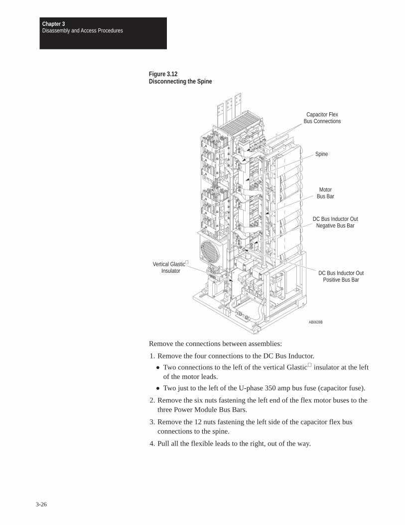
Chapter 3Disassembly and Access Procedures
3-26
Figure 3.12Disconnecting the Spine
AB0639B
Capacitor FlexBus Connections
Spine
MotorBus Bar
DC Bus Inductor OutNegative Bus Bar
DC Bus Inductor OutPositive Bus Bar
Vertical Glastic
Insulator
Remove the connections between assemblies:
1. Remove the four connections to the DC Bus Inductor.
Two connections to the left of the vertical Glastic insulator at the leftof the motor leads.
Two just to the left of the U-phase 350 amp bus fuse (capacitor fuse).
2. Remove the six nuts fastening the left end of the flex motor buses to thethree Power Module Bus Bars.
3. Remove the 12 nuts fastening the left side of the capacitor flex busconnections to the spine.
4. Pull all the flexible leads to the right, out of the way.

Chapter 3Disassembly and Access Procedures
3-27
Figure 3.13Removing the Spine
AB0680A
Capacitor FlexBus Connections
Spine
MotorBus Bar
DC Bus Inductor OutNegative Bus Bar
DC Bus Inductor OutPositive Bus Bar
Vertical Glastic
Insulator
1. Remove the spine.
Push the spine carefully to the right.
Lift it out of the drive without forcing it.
2. Remove the six Gate Driver connectors from the Power Module GateInterface Boards. Pinch the sides of the connector body while pullingback.
3. Disconnect any remaining wiring between the Inverter HousingAssembly and the Capacitor Bank Assembly.
4. Disconnect the Inverter Housing Assembly ground cable from theground plate at the bottom of the main assembly.
5. Remove the wheel chocks at the bottom of the Inverter HousingAssembly.
6. Pull the assembly onto a platform (see Figure 3.14 forrecommendations). Use the handle attached to the Fan 2 housing.
Chapter 3Disassembly and Access Procedures
3-28
ATTENTION: Hazard of tipping and severe injury exists. Thisprocess requires two people. The platform must be able to suppor909 kg (2,000 lbs).
Installation
Install the Inverter Housing Assembly in reverse order of removal.
IMPORTANT: When pushing the Inverter Housing Assembly into thedrive, you may need to have someone tip the unit slightly to the left orright to center it between the guides at the back of the Enclosure. Adjustthe angle brackets at the ends of the T-bar crossbar.
ATTENTION: Replace all guards before applying power to thedrive. Failure to replace guards may result in death or seriousinjury.

Chapter 3Disassembly and Access Procedures
3-29
Figure 3.14Service Platform
AB0681A
30”25”
Height tosuit
installation
Stop Block
Fan 2 Handle
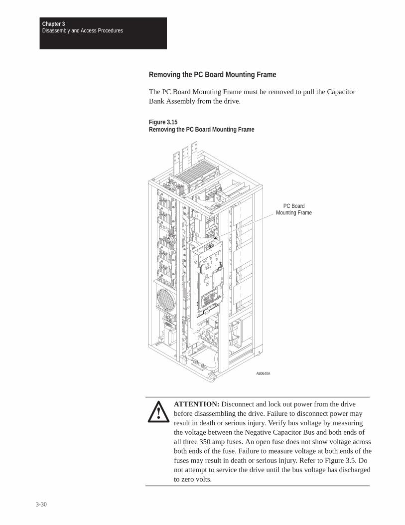
Chapter 3Disassembly and Access Procedures
3-30
Removing the PC Board Mounting Frame
The PC Board Mounting Frame must be removed to pull the CapacitorBank Assembly from the drive.
Figure 3.15Removing the PC Board Mounting Frame
AB0640A
PC BoardMounting Frame
ATTENTION: Disconnect and lock out power from the drivebefore disassembling the drive. Failure to disconnect power mayresult in death or serious injury. Verify bus voltage by measuringthe voltage between the Negative Capacitor Bus and both ends ofall three 350 amp fuses. An open fuse does not show voltage acrossboth ends of the fuse. Failure to measure voltage at both ends of thefuses may result in death or serious injury. Refer to Figure 3.5. Donot attempt to service the drive until the bus voltage has dischargedto zero volts.

Chapter 3Disassembly and Access Procedures
3-31
ATTENTION: Wear a wrist-type grounding strap when servicing1336 PLUS Drives. Failure to protect drive components againstESD may damage drive components. Refer to ElectrostaticDischarge Precautions in Chapter 3 – Disassembly and AccessProcedures.
IMPORTANT: Before you remove connections and wires from the drivecomponents, mark the connections and wires to correspond with theircomponent connections and terminals to prevent incorrect wiring duringassembly.
Removal
1. Remove power from the drive.
2. Turn the enclosure door latches 1/4 turn counterclockwise to open theenclosure door.
3. Turn the latches, located on the left side of the PC Board MountingFrame, to open the PC Board Mounting Frame.
4. Check for zero volts between +DC and –DC. Refer to Figure 3.5.
5. Check for the absence of control voltage at the points marked on theMain Control Board.
6. Disconnect any wires connecting the PC Board Mounting Frame witheither main assembly.
7. Open the PC Board Mounting Frame all the way to the right.
8. Lift the frame straight up to remove it from the hinges.
Installation
Install the PC Board Mounting Frame in reverse order of removal.
ATTENTION: Replace all guards before applying power to thedrive. Failure to replace guards may result in death or seriousinjury.
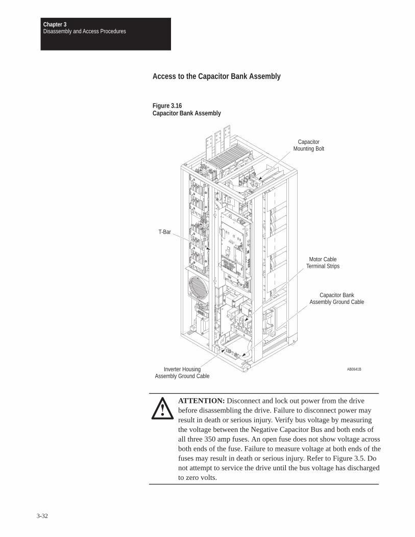
Chapter 3Disassembly and Access Procedures
3-32
Access to the Capacitor Bank Assembly
Figure 3.16Capacitor Bank Assembly
AB0641B
CapacitorMounting Bolt
T-Bar
Motor CableTerminal Strips
Capacitor BankAssembly Ground Cable
Inverter HousingAssembly Ground Cable
ATTENTION: Disconnect and lock out power from the drivebefore disassembling the drive. Failure to disconnect power mayresult in death or serious injury. Verify bus voltage by measuringthe voltage between the Negative Capacitor Bus and both ends ofall three 350 amp fuses. An open fuse does not show voltage acrossboth ends of the fuse. Failure to measure voltage at both ends of thefuses may result in death or serious injury. Refer to Figure 3.5. Donot attempt to service the drive until the bus voltage has dischargedto zero volts.

Chapter 3Disassembly and Access Procedures
3-33
ATTENTION: Wear a wrist-type grounding strap when servicing1336 PLUS Drives. Failure to protect drive components againstESD may damage drive components. Refer to ElectrostaticDischarge Precautions at the beginning of this chapter.
IMPORTANT: Before you remove connections and wires from the drivecomponents, mark the connections and wires to correspond with theircomponent connections and terminals to prevent incorrect wiring duringassembly.
Removal
ATTENTION: To remove either the Inverter Housing Assemblyor the Capacitor Bank Assembly safely requires two persons.Attempting to remove either assembly by yourself may result indeath or serious injury.
ATTENTION: Do not remove both the Inverter Housing and theCapacitor Bank assemblies at the same time.
Access the drive:
1. Remove power from the drive.
2. Turn the enclosure door latches 1/4 turn counterclockwise to open theenclosure door.
3. Open the PC Board Mounting Frame.
4. Check for zero volts between +DC and –DC. Refer to Figure 3.5.
5. Check for the absence of control voltage at the points marked on theMain Control Board
6. Remove the motor cable connections from the terminal strips at thebottom right of the drive.
7. Remove the PC Board Mounting Frame. Refer to Removing the PCBoard Mounting Frame in this chapter.
Remove the T-Bar:
IMPORTANT: Refer to Figure 3.11.
1. Remove power from the drive.
2. Turn the enclosure door latches 1/4 turn counterclockwise to open theenclosure door.
3. Open the PC Board Mounting Frame.

Chapter 3Disassembly and Access Procedures
3-34
4. Check for zero volts between +DC and –DC. Refer to Figure 3.5.
Remove the connections between assemblies:
IMPORTANT: Refer to Figure 3.12.
1. Remove the four connections to the DC Bus Inductor.
Two connections to the left of the vertical Glastic insulator at the leftof the motor leads.
Two just to the left of the U-phase 350 amp bus fuse (capacitor fuse).
2. Remove the six nuts fastening the left end of the motor flex buses to thethree Power Module Bus Bars.
3. Remove the 12 nuts fastening the left side of the capacitor flex busconnections to the spine.
4. Pull all the flexible leads to the right, out of the way.
5. Remove the spine.
Push the spine carefully to the right.
Lift it out of the drive without forcing it.
Access the Capacitor Bank Assembly:
1. Disconnect the Inverter Housing Assembly ground cable from theground plate at the bottom of the main frame.
2. Disconnect the Capacitor Bank Assembly ground cable.
3. Disconnect any ground wires that obstruct removal of the assembly.
4. Remove the capacitor mounting bolt at the top center of the capacitorframe.
5. Remove the wheel chocks at the bottom of the Capacitor BankAssembly.
6. Pull the assembly onto a platform. Refer to Figure 3.14.
ATTENTION: Hazard of tipping and severe injury exists. Thisprocess requires two people. The platform must be able to support909 kg (2,000 lbs).
Installation
Install the Capacitor Bank Assembly in reverse order of removal.
IMPORTANT: Guide the unit into place so that it mates with thelock-down bolt at the top of the capacitor frame. Adjust the angle bracketsat the ends of the T-bar crossbar.
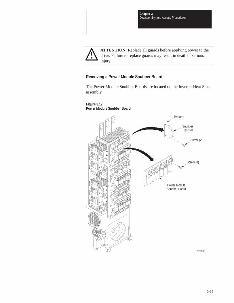
Chapter 3Disassembly and Access Procedures
3-35
ATTENTION: Replace all guards before applying power to thedrive. Failure to replace guards may result in death or seriousinjury.
Removing a Power Module Snubber Board
The Power Module Snubber Boards are located on the Inverter Heat Sinkassembly.
Figure 3.17Power Module Snubber Board
AB0602A
Power ModuleSnubber Board
SnubberResistor
Screw (2)
Preform
Screw (8)
Chapter 3Disassembly and Access Procedures
3-36
Removal
ATTENTION: Disconnect and lock out power from the drivebefore disassembling the drive. Failure to disconnect power mayresult in death or serious injury. Verify bus voltage by measuringthe voltage between the Negative Capacitor Bus and both ends ofall three 350 amp fuses. An open fuse does not show voltage acrossboth ends of the fuse. Failure to measure voltage at both ends of thefuses may result in death or serious injury. Refer to Figure 3.5. Donot attempt to service the drive until the bus voltage has dischargedto zero volts.
ATTENTION: Hazard of electric shock exists. Up to 1,600 VDCwill be on Power Module Snubber Board Connector J1 if theSnubber Resistor is open. Measure for zero (0) VDC from SnubberBoard terminal TP3 to plus (+) bus before removing connector J1.Use a resistor greater than 1 ohm and less than 100 ohm, rated for25 watts minimum, between pins 1 and 2 of connector J1 todischarge any voltage.
ATTENTION: Wear a wrist-type grounding strap when servicing1336 PLUS Drives. Failure to protect drive components againstESD may damage drive components. Refer to ElectrostaticDischarge Precautions at the beginning of this chapter.
IMPORTANT: Before you remove connections and wires from the drivecomponents, mark the connections and wires to correspond with theircomponent connections and terminals to prevent incorrect wiring duringassembly.
1. Access the Inverter Housing Assembly. Refer to Chapter 3 –Disassembly and Access Procedures, Access to the Inverter HousingAssembly.
2. Remove the snubber resistor J1 and J2 connections from the snubberboard.
3. Remove the screws fastening the Power Module Snubber Board to thesnubber bus bars.

Chapter 3Disassembly and Access Procedures
3-37
Installation
ATTENTION: Do not substitute longer or shorter hardware whenfastening the Power Module components to the Power Modules.Use the same size fastener to fasten the components as wasoriginally used. Using different fastener lengths will damage thePower Modules.
Install the Power Module Snubber Board in reverse order of removal. Referto Table 3.A – Fastener Torque Specifications.
ATTENTION: Replace all guards before applying power to thedrive. Failure to replace guards may result in death or seriousinjury.

Chapter 3Disassembly and Access Procedures
3-38
Removing an Input Rectifier Snubber Board
The Input Rectifier Snubber Boards are located on the Inverter HousingAssembly, under the Guard, between the heat sinks and the vertical bus.
Figure 3.18Input Rectifier Snubber Board
AB0629A
Input RectifierSnubber Board
Guard
SCRs andHeat Sinks

Chapter 3Disassembly and Access Procedures
3-39
Removal
ATTENTION: Disconnect and lock out power from the drivebefore disassembling the drive. Failure to disconnect power mayresult in death or serious injury. Verify bus voltage by measuringthe voltage between the Negative Capacitor Bus and both ends ofall three 350 amp fuses. An open fuse does not show voltage acrossboth ends of the fuse. Failure to measure voltage at both ends of thefuses may result in death or serious injury. Refer to Figure 3.5. Donot attempt to service the drive until the bus voltage has dischargedto zero volts.
ATTENTION: Wear a wrist-type grounding strap when servicing1336 PLUS Drives. Failure to protect drive components againstESD may damage drive components. Refer to ElectrostaticDischarge Precautions at the beginning of this chapter.
IMPORTANT: Before you remove connections and wires from the drivecomponents, mark the connections and wires to correspond with theircomponent connections and terminals to prevent incorrect wiring duringassembly.
1. Access the Inverter Housing Assembly. Refer to Chapter 3 –Disassembly and Access Procedures, Access to the Inverter HousingAssembly.
2. Remove the plastic guard by removing the screws fastening the left sideof the guard to the SCR-heat sink assembly.
3. Remove the screws fastening the Input Rectifier Snubber Board to theAC and DC snubber buses.
4. Remove the snubber board.
InstallationInstall the Input Rectifier Snubber Board in reverse order of removal. Referto Table 3.A – Fastener Torque Specifications.
ATTENTION: Replace all guards before applying power to thedrive. Failure to replace guards may result in death or seriousinjury.

Chapter 3Disassembly and Access Procedures
3-40
This Page Intentionally Left Blank.

Chapter
4-1
Component Test Procedures
Chapter Objectives The following tests help you troubleshoot B300 – B600, C300 – C600, andBX250 drives.
Component Test In some cases, different tests troubleshoot components of the same name.
Overview These similar tests vary according to the rating of the drive being tested.Verify that the rating on the drive matches the rating for the test you areperforming.
ATTENTION: Some printed circuit boards and drive componentsmay contain hazardous voltage levels. Remove and lock out powerbefore you disconnect or reconnect wires, and before you removeor replace fuses and circuit boards. Verify bus voltage bymeasuring the voltage between the Negative Capacitor Bus andboth ends of all three 350 amp fuses. An open fuse does not showvoltage across both ends of the fuse. Failure to measure voltage atboth ends of the fuses may result in death or serious injury. Refer toFigure 3.5. Do not attempt to service the drive until the bus voltagehas discharged to zero volts.
ATTENTION: Servicing energized industrial control equipmentcan be hazardous. Electrical shock, burns, or unintentionalactuation of controlled industrial equipment may cause death orserious injury. Follow the safety-related practices of NFPA 70E,Electrical Safety for Employee Workplaces, when working on ornear energized equipment. Do not work alone on energizedequipment.

Chapter 4Component Test Procedures
4-2
Electrostatic Discharge Precautions
ATTENTION: This assembly contains parts and sub-assembliesthat are sensitive to electrostatic discharge. Static controlprecautions are required when servicing this assembly. Componentdamage may result if you ignore electrostatic discharge controlprocedures. If you are not familiar with static control procedures,reference Allen-Bradley Publication 8000-4.5.2, Guarding AgainstElectrostatic Discharge, or any other applicable ESD protectionhandbook.
Electrostatic discharge generated by static electricity can damage thecomplimentary metallic oxide semiconductor devices on various driveboards. It is recommended that you perform these procedures to guardagainst this type of damage when circuit boards are removed or installed:
Wear a wrist type grounding strap that is grounded to the chassis.
Attach the wrist strap before removing the new circuit board from theconductive packet.
Remove boards from the drive and immediately insert them into theirconductive packets.
Tools
For a list of tools required, tightening sequences, and fastener torquespecifications, refer to Chapter 3 – Disassembly and Access Procedures,Fastener Torque Specifications.

Chapter 4Component Test Procedures
4-3
Test 1 The Gate Driver Board is located behind the Main Control Board, on the
Testing the Gate PC Board Mounting Frame. If you have replaced power modules, you
Driver Board should also replace the Gate Driver Board. If a new Gate Driver Board isnot available, you must test the old board, using the following procedure.
Figure 4.1Gate Driver Board Test
AB0604B
F3
VR2VR3VR5
VR6
VR1
VR4F1
Gate DriverBoard
D78
D71
D72
D65
D66
D10
ATTENTION: Disconnect and lock out power from the drivebefore disassembling the drive. Failure to disconnect power mayresult in death or serious injury. Verify bus voltage by measuringthe voltage between the Negative Capacitor Bus and both ends ofall three 350 amp fuses. An open fuse does not show voltage acrossboth ends of the fuse. Failure to measure voltage at both ends of thefuses may result in death or serious injury. Refer to Figure 3.5. Donot attempt to service the drive until the bus voltage has dischargedto zero volts.

Chapter 4Component Test Procedures
4-4
ATTENTION: Wear a wrist-type grounding strap when servicing1336 PLUS Drives. Failure to protect drive components againstESD may damage drive components. Refer to ElectrostaticDischarge Precautions in Chapter 3 – Disassembly and AccessProcedures.
IMPORTANT: Before you remove connections and wires from the drivecomponents, mark the connections and wires to correspond with theircomponent connections and terminals to prevent incorrect wiring duringassembly.
1. Remove power from the drive.
2. Turn the enclosure door latches 1/4 turn counterclockwise to open theenclosure door.
3. Open the PC Board Mounting Frame.
4. Check for zero volts between +DC and –DC. Refer to Figure 3.5.
5. Check for the absence of control voltage at the points marked on theMain Control Board.
6. Remove the Main Control Board Mounting Plate. Refer to Chapter 3 –Disassembly and Access Procedures, Removing the Main Control BoardMounting Plate.
7. Test Gate Driver Board fuses F1 and F3 for an open condition. Replacethe Gate Driver Board if either fuse shows an open condition.
8. Set your meter to test diodes.
9. Test VR1 – VR6. The following table shows meter connections at thecomponents and ideal meter readings for those connections. Refer to theprevious illustration for component locations.
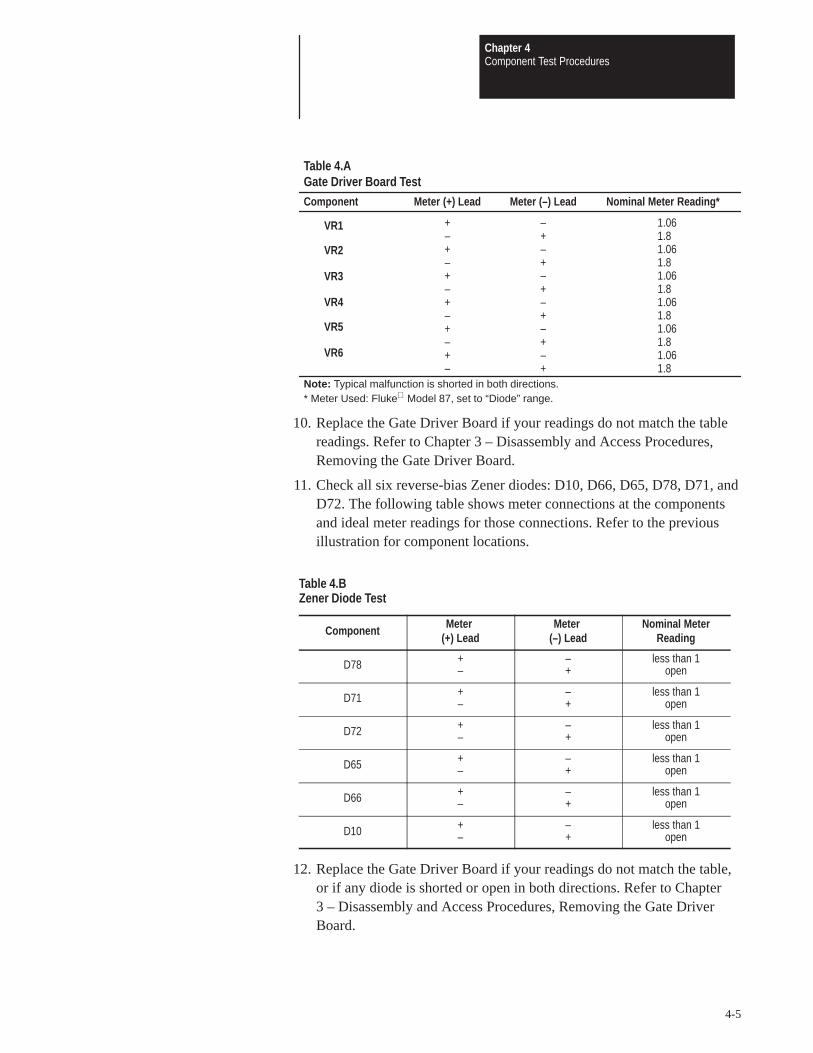
Chapter 4Component Test Procedures
4-5
Component Meter (+) Lead Meter (–) Lead Nominal Meter Reading*
+ – 1.06– + 1.8+ – 1.06– + 1.8+ – 1.06– + 1.8+ – 1.06– + 1.8+ – 1.06– + 1.8+ – 1.06– + 1.8
Note: Typical malfunction is shorted in both directions.* Meter Used: Fluke Model 87, set to “Diode” range.
Table 4.AGate Driver Board Test
VR1
VR2
VR3
VR4
VR5
VR6
10. Replace the Gate Driver Board if your readings do not match the tablereadings. Refer to Chapter 3 – Disassembly and Access Procedures,Removing the Gate Driver Board.
11. Check all six reverse-bias Zener diodes: D10, D66, D65, D78, D71, andD72. The following table shows meter connections at the componentsand ideal meter readings for those connections. Refer to the previousillustration for component locations.
Table 4.BZener Diode Test
Component Meter (+) Lead
Meter (–) Lead
Nominal MeterReading
D78 +–
–+
less than 1open
D71 +–
–+
less than 1open
D72 +–
–+
less than 1open
D65 +–
–+
less than 1open
D66 +–
–+
less than 1open
D10 +–
–+
less than 1open
12. Replace the Gate Driver Board if your readings do not match the table,or if any diode is shorted or open in both directions. Refer to Chapter3 – Disassembly and Access Procedures, Removing the Gate DriverBoard.

Chapter 4Component Test Procedures
4-6
ATTENTION: When removing the entire wire harness connectingGate Driver Board connector J9 to Precharge Board connector J3,align the wires on the harness terminals with the pins on the boardconnectors. Incorrect harness connection may result in faulty driveoperation and may damage the equipment.
ATTENTION: Replace all guards before applying power to thedrive. Failure to replace guards may result in death or seriousinjury.
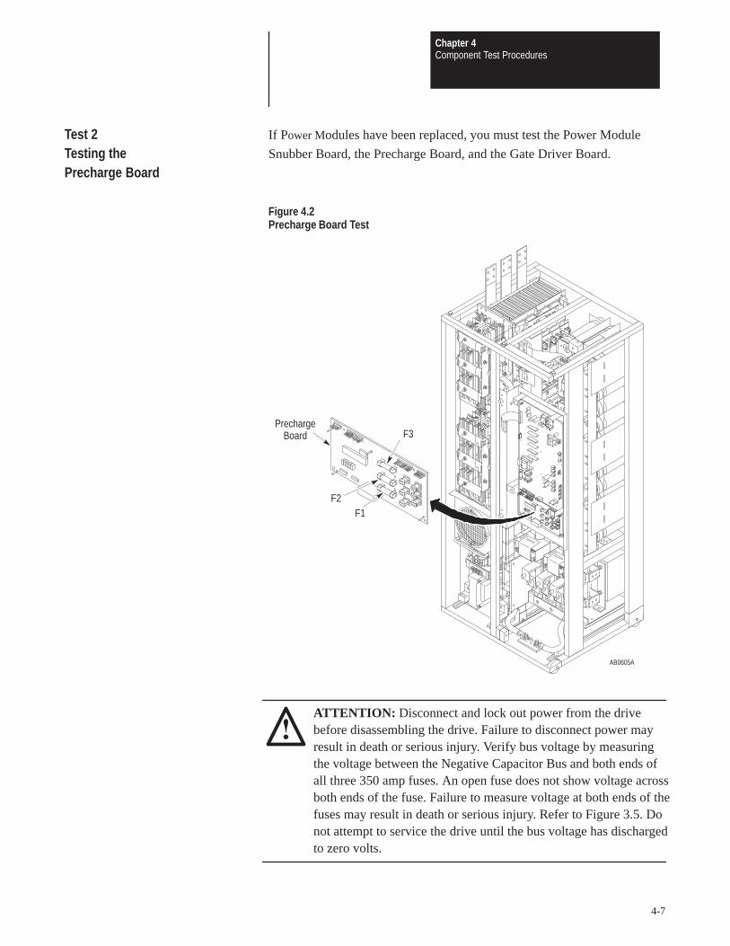
Chapter 4Component Test Procedures
4-7
Test 2 If Power Modules have been replaced, you must test the Power Module
Testing the Snubber Board, the Precharge Board, and the Gate Driver Board.
Precharge Board
Figure 4.2Precharge Board Test
AB0605A
PrechargeBoard F3
F2F1
ATTENTION: Disconnect and lock out power from the drivebefore disassembling the drive. Failure to disconnect power mayresult in death or serious injury. Verify bus voltage by measuringthe voltage between the Negative Capacitor Bus and both ends ofall three 350 amp fuses. An open fuse does not show voltage acrossboth ends of the fuse. Failure to measure voltage at both ends of thefuses may result in death or serious injury. Refer to Figure 3.5. Donot attempt to service the drive until the bus voltage has dischargedto zero volts.

Chapter 4Component Test Procedures
4-8
ATTENTION: Wear a wrist-type grounding strap when servicing1336 PLUS Drives. Failure to protect drive components againstESD may damage drive components. Refer to ElectrostaticDischarge Precautions in Chapter 3 – Disassembly and AccessProcedures.
IMPORTANT: Before you remove connections and wires from the drivecomponents, mark the connections and wires to correspond with theircomponent connections and terminals to prevent incorrect wiring duringassembly.
1. Remove power from the drive.
2. Turn the enclosure door latches 1/4 turn counterclockwise to open theenclosure door.
3. Open the PC Board Mounting Frame.
4. Check for zero volts between +DC and –DC. Refer to Figure 3.5.
5. Check for the absence of control voltage at the points marked on theMain Control Board.
6. Set your meter to test resistance.
7. Test Precharge Board fuses F1, F2, and F3 for open conditions.
8. Replace the Precharge Board if any fuse shows an open condition. Referto Chapter 3 – Disassembly and Access Procedures, Removing thePrecharge Board.
ATTENTION: Replace all guards before applying power to thedrive. Failure to replace guards may result in death or seriousinjury.
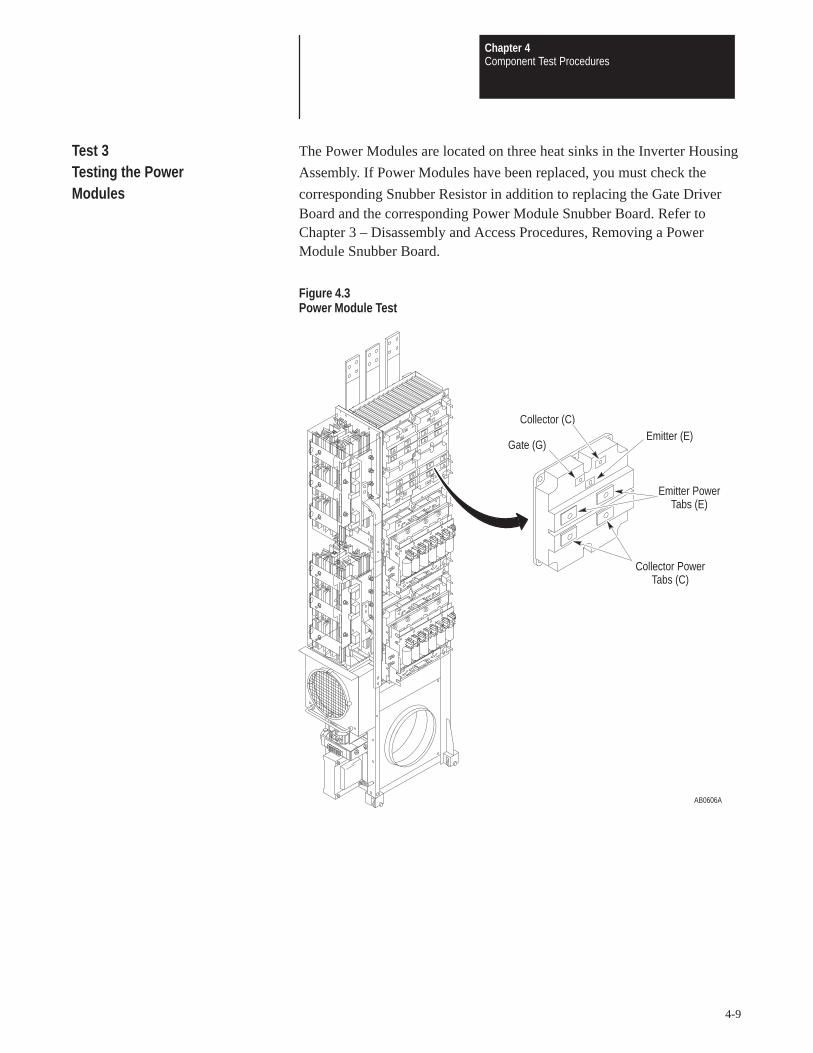
Chapter 4Component Test Procedures
4-9
Test 3 The Power Modules are located on three heat sinks in the Inverter Housing
Testing the Power Assembly. If Power Modules have been replaced, you must check the
Modules corresponding Snubber Resistor in addition to replacing the Gate DriverBoard and the corresponding Power Module Snubber Board. Refer toChapter 3 – Disassembly and Access Procedures, Removing a PowerModule Snubber Board.
Figure 4.3Power Module Test
AB0606A
Gate (G)
Collector (C)Emitter (E)
Emitter PowerTabs (E)
Collector PowerTabs (C)

Chapter 4Component Test Procedures
4-10
ATTENTION: Disconnect and lock out power from the drivebefore disassembling the drive. Failure to disconnect power mayresult in death or serious injury. Verify bus voltage by measuringthe voltage between the Negative Capacitor Bus and both ends ofall three 350 amp fuses. An open fuse does not show voltage acrossboth ends of the fuse. Failure to measure voltage at both ends of thefuses may result in death or serious injury. Refer to Figure 3.5. Donot attempt to service the drive until the bus voltage has dischargedto zero volts.
ATTENTION: Wear a wrist-type grounding strap when servicing1336 PLUS Drives. Failure to protect drive components againstESD may damage drive components. Refer to ElectrostaticDischarge Precautions in Chapter 3 – Disassembly and AccessProcedures.
IMPORTANT: Before you remove connections and wires from the drivecomponents, mark the connections and wires to correspond with theircomponent connections and terminals to prevent incorrect wiring duringassembly.
1. Access the Inverter Housing Assembly. Refer to Chapter 3 –Disassembly and Access Procedures, Access to the Inverter HousingAssembly.
2. Remove the Power Module Snubber Board. Refer to Chapter 3 –Disassembly and Access Procedures, Removing a Power ModuleSnubber Board.
3. Set your meter to test diodes.
4. Test the Power Modules. The following table shows meter connectionsand ideal meter readings for those connections. Refer to the formerillustration for meter connection locations.
Meter (+) Lead Meter (–) Lead Nominal Meter Reading
E C 0.218 – 0.418E G InfiniteC E InfiniteC G InfiniteG E InfiniteG C Infinite
Table 4.CPower Modules

Chapter 4Component Test Procedures
4-11
5. Replace a Power Module if meter readings are not as shown. Refer toChapter 5 – Part Replacement Procedures, Power Modules.
6. Set your meter to measure resistance.
7. Test the Power Module Snubber Resistors. The reading should be 16ohms each. If open, replace the snubber resistor.
Figure 4.4Power Module Snubber Resistors
AB0998A
SnubberResistor
Note: Two 16 ohm resistors are in parallel when plugged into a snubber board,resulting in 8 ohms total.
ATTENTION: Replace all guards before applying power to thedrive. Failure to replace guards may result in death or seriousinjury.
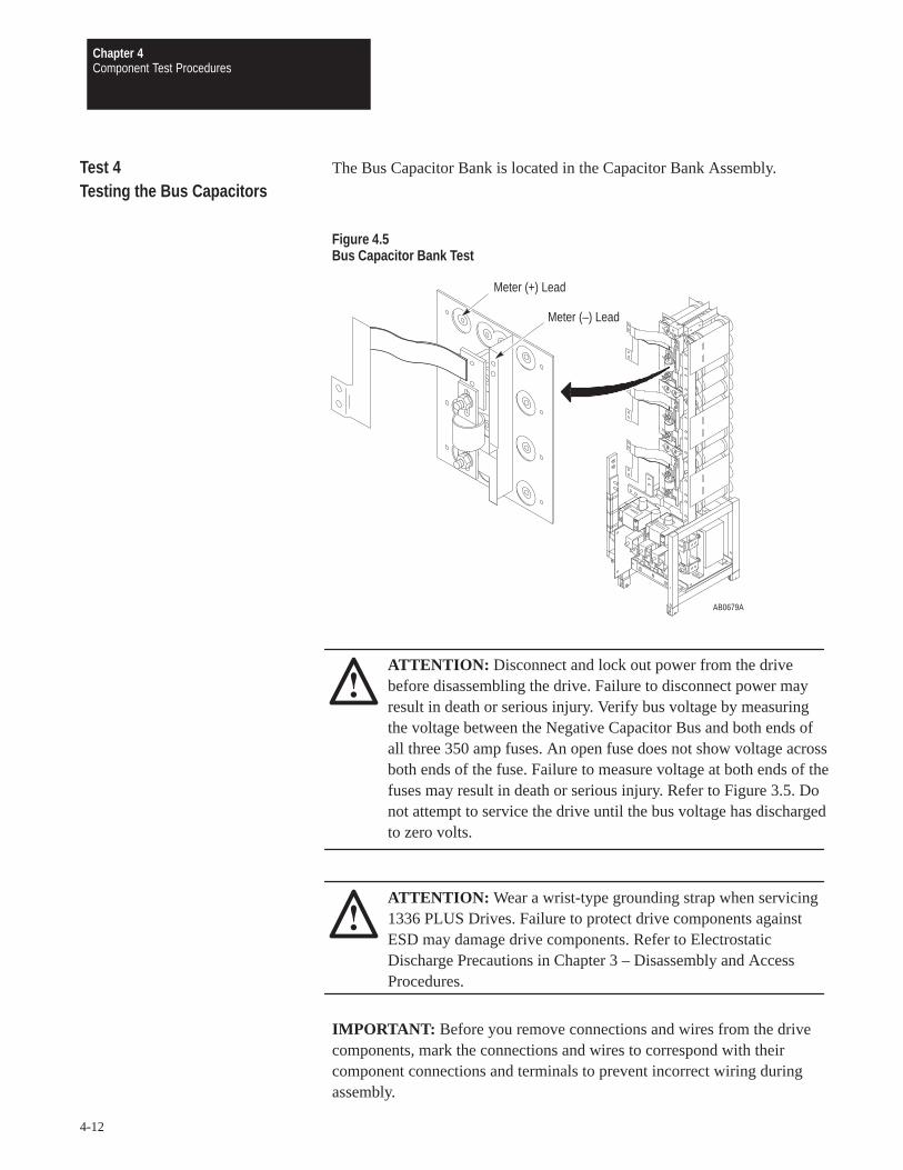
Chapter 4Component Test Procedures
4-12
Test 4 The Bus Capacitor Bank is located in the Capacitor Bank Assembly.
Testing the Bus Capacitors
Figure 4.5Bus Capacitor Bank Test
AB0679A
Meter (–) Lead
Meter (+) Lead
ATTENTION: Disconnect and lock out power from the drivebefore disassembling the drive. Failure to disconnect power mayresult in death or serious injury. Verify bus voltage by measuringthe voltage between the Negative Capacitor Bus and both ends ofall three 350 amp fuses. An open fuse does not show voltage acrossboth ends of the fuse. Failure to measure voltage at both ends of thefuses may result in death or serious injury. Refer to Figure 3.5. Donot attempt to service the drive until the bus voltage has dischargedto zero volts.
ATTENTION: Wear a wrist-type grounding strap when servicing1336 PLUS Drives. Failure to protect drive components againstESD may damage drive components. Refer to ElectrostaticDischarge Precautions in Chapter 3 – Disassembly and AccessProcedures.
IMPORTANT: Before you remove connections and wires from the drivecomponents, mark the connections and wires to correspond with theircomponent connections and terminals to prevent incorrect wiring duringassembly.

Chapter 4Component Test Procedures
4-13
Access the drive:
1. Remove power from the drive.
2. Turn the enclosure door latches 1/4 turn counterclockwise to open theenclosure door.
3. Open the PC Board Mounting Frame.
4. Check for zero volts between +DC and –DC. Refer to Figure 4.5.
5. Check for the absence of control voltage at the points marked on theMain Control Board.
Test the Capacitors:
1. Set your meter to test voltage.
2. Connect the negative lead of the meter to –DC and the positive lead tothe capacitor terminal called out in Figure 4.5.
ATTENTION: Servicing energized industrial control equipmentcan be hazardous. Electrical shock, burns, or unintentionalactuation of controlled industrial equipment may cause death orserious injury. Follow the safety-related practices of NFPA 70E,Electrical Safety for Employee Workplaces, when working on ornear energized equipment. Do not work alone on energizedequipment.
3. Apply power AFTER the meter is connected, otherwise your meter willread zero volts.
Refer to Table 4.D for nominal meter readings.
Table 4.DCapacitor Test Meter Readings
Drive Series Input Volts Meter
380 V 178 V
B 415 V 193 V
480 V 218 V
500 V 233 V
C 575 V 267 V
600 V 283 V
If the capacitors are normal, the meter reading should be one third the voltage across thetotal capacitor bank.
4. Using this procedure, test each of the three Capacitor Bank sections.Table 4.E shows the correct voltage for the total Capacitor Bank.

Chapter 4Component Test Procedures
4-14
Table 4.EBus Capacitor Bank Test
DriveRating
InputVolts
Meter Reading
B380415480
535V DC +/–10%580V DC +/–10%650V DC +/–10%
C500575600
700V DC +/–10%800V DC +/–10%850V DC +/–10%
5. If the voltage is out of tolerance, check the following:
An open condition at an Input Rectifier.
A voltage drop due to DC Bus Inductor resistance.
A voltage drop between an Input Rectifier and the bus capacitors dueto loose or resistive wires or connections.
Precharge circuit problems.
6. If the above check does not reveal a problem, replace the Bus CapacitorBank and Load-Sharing Resistors. Refer to Chapter 5 – PartReplacement Procedures, Bus Capacitor Bank.
ATTENTION: Replace all guards before applying power to thedrive. Failure to replace guards may result in death or seriousinjury.

Chapter 4Component Test Procedures
4-15
Test 5 The SCRs are located in the heat sinks on the Inverter Housing
Testing the SCRs Assembly.
ATTENTION: Disconnect and lock out power from the drivebefore disassembling the drive. Failure to disconnect power mayresult in death or serious injury. Verify bus voltage by measuringthe voltage between the Negative Capacitor Bus and both ends ofall three 350 amp fuses. An open fuse does not show voltage acrossboth ends of the fuse. Failure to measure voltage at both ends of thefuses may result in death or serious injury. Refer to Figure 3.5. Donot attempt to service the drive until the bus voltage has dischargedto zero volts.
ATTENTION: Wear a wrist-type grounding strap when servicing1336 PLUS Drives. Failure to protect drive components againstESD may damage drive components. Refer to ElectrostaticDischarge Precautions in Chapter 3 – Disassembly and AccessProcedures.
IMPORTANT: Before you remove connections and wires from the drivecomponents, mark the connections and wires to correspond with theircomponent connections and terminals to prevent incorrect wiring duringassembly.
Access the drive:
1. Remove power from the drive.
2. Turn the enclosure door latches 1/4 turn counterclockwise to open theenclosure door.
3. Open the PC Board Mounting Frame.
4. Check for zero volts between +DC and –DC. Refer to Figure 3.5.
5. Check for the absence of control voltage at the points marked on theMain Control Board.
6. Set your meter to test resistance.
7. Measure resistance from AC inputs L1, L2, and L3 to +DC. Refer toTable 4.F.
8. Measure between each pair of gate and cathode terminals on thePrecharge Board. Refer to Table 4.G.
The following tables show meter connections and ideal meter readings forthose connections. Refer to the schematic in this manual for moreinformation.

Chapter 4Component Test Procedures
4-16
Table 4.FSCR Test at AC Input
Meter (+) Lead Meter (–) Lead Nominal Meter Reading
L1
L2 +DC
L3> 10kΩ
L1> 10kΩ
L2 –DC
L3
Table 4.GSCR Test at Precharge Board
SCR Meter (+) Lead Meter (–) Lead Nominal MeterReading
J1 Connector
SCR1R1G R1K 10
SCR1R1K R1G 10
SCR3S1G S1K 10
SCR3S1G S1G 10
SCR5T1G T1K 10
SCR5T1K T1G 10
J2 Connector
SCR4R2G R2K 10
SCR4R2K R2G 10
SCR6S2G S2K 10
SCR6S2K S2G 10
SCR2T2G T2K 10
SCR2T2K T2G 10
9. Replace the SCR if any meter readings are not as shown. Refer toChapter 5 – Part Replacement Procedures, SCRs.
10. If an SCR requires replacement, check the Power Modules for damage.Refer to Testing the Power Modules in this chapter.
ATTENTION: Replace all guards before applying power to thedrive. Failure to replace guards may result in death or seriousinjury.

Chapter
5-1
Part Replacement Procedures
Chapter Objective This chapter describes procedures required to replace drive components.This chapter references Chapter 3 – Disassembly and Access Proceduresfor basic drive component access.
Part Replacement The part replacement procedures in this chapter assume that the drive you
Overview are servicing either has no enclosure or that the enclosure is open. For moreinformation on opening the Drive Enclosure, refer to Chapter 3 –Disassembly and Access Procedures, Opening the Drive Enclosure.
Safety Precautions
ATTENTION: Some printed circuit boards and drive componentsmay contain hazardous voltage levels. Remove power before youdisconnect or reconnect wires, and before you remove or replacefuses and circuit boards. Verify bus voltage by measuring thevoltage between between the Negative Capacitor Bus and bothends of all three 350 amp fuses. An open fuse does not showvoltage across both ends of the fuse. Failure to measure voltage atboth ends of the fuses may result in death or serious injury. Refer toFigure 3.5. Do not attempt to service the drive until the bus voltagehas discharged to zero volts.

Chapter 5Part Replacement Procedures
5-2
Electrostatic Discharge Precautions
ATTENTION: This assembly contains parts and sub-assembliesthat are sensitive to electrostatic discharge. Static controlprecautions are required when servicing this assembly. Componentdamage may result if you ignore electrostatic discharge controlprocedures. If you are not familiar with static control procedures,reference Allen-Bradley Publication 8000–4.5.2, Guarding AgainstElectrostatic Discharge, or any other applicable ESD protectionhandbook.
Electrostatic discharge generated by static electricity can damage thecomplimentary metallic oxide semiconductor devices on various driveboards. It is recommended that you perform these procedures to guardagainst this type of damage when circuit boards are removed or installed:
Wear a wrist type grounding strap that is grounded to the chassis.
Attach the wrist strap before removing the new circuit board from theconductive packet.
Remove boards from the drive and immediately insert them into theirconductive packets.
For a list of tools required, tightening sequences, and fastener torquespecifications, refer to Chapter 3 – Disassembly and Access Procedures,Fastener Torque Specifications.

Chapter 5Part Replacement Procedures
5-3
Major Component This section explains in detail how to replace the following drive
Replacement components:
Bus Capacitor Bank
Thermistor
Power Modules
Power Module Snubber Resistor
SCRs
Fans and Transformer Assembly
DC Bus Inductor
Ground Sense CT
Bus Fuses
LEMs
MOV Surge Suppressor
Thermal Switch
For Gate Driver Board, Precharge Board, Main Control Board, SnubberBoard, and Control Interface Board installation and removal procedures,refer to Chapter 3.
Detailed Product Allen-Bradley Adjustable Frequency AC Drives are modular by design to
Identification enhance troubleshooting and spare parts replacement, thereby helpingreduce production down-time.
The following illustration calls out the main components of a typical drive.Component designs vary slightly among the different drive ratings, butcomponent locations are identical.

Chapter 5Part Replacement Procedures
5-4
Figure 5.1Main Drive Components
AB0618A
PowerModule
GroundSense CT
Input RectifierSnubber Board
Power ModuleBus Bar
Power ModuleGate Interface
Board
LEM
FanTransformer
FanCapacitor
DC BusInductor
MOV SurgeSuppressor
Bus FuseF1
Bus CapacitorBank
ControlInterface Board
Main ControlBoard
Main Control BoardMounting Plate
PrechargeBoard
PrechargeBoard Fuses
Gate DriverBoard
Fuse F3
Fuse F1
Power ModuleSnubber Board
Thermistor
Power ModuleSnubber Resistor
Fan 1
Fan 2
ThermalSwitch
SCR
Load SharingResistor
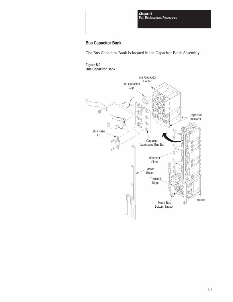
Chapter 5Part Replacement Procedures
5-5
Bus Capacitor Bank
The Bus Capacitor Bank is located in the Capacitor Bank Assembly.
Figure 5.2Bus Capacitor Bank
AB0608A
Bus CapacitorCap
Bus CapacitorHolder
CapacitorLaminated Bus Bar
Bus FuseF1
TerminalStrips
Motor BusBottom Support
CapacitorInsulator
BalancerPlate
MotorBuses

Chapter 5Part Replacement Procedures
5-6
Removal
ATTENTION: Disconnect and lock out power from the drivebefore disassembling the drive. Failure to disconnect power mayresult in death or serious injury. Verify bus voltage by measuringthe voltage between between the Negative Capacitor Bus and bothends of all three 350 amp fuses. An open fuse does not showvoltage across both ends of the fuse. Failure to measure voltage atboth ends of the fuses may result in death or serious injury. Refer toFigure 3.5. Do not attempt to service the drive until the bus voltagehas discharged to zero volts.
ATTENTION: Wear a wrist-type grounding strap when servicing1336 PLUS Drives. Failure to protect drive components againstESD may damage drive components. Refer to ElectrostaticDischarge Precautions at the beginning of this chapter.
IMPORTANT: Before you remove connections and wires from drivecomponents, mark the connections and wires to correspond with theircomponent connections and terminals to prevent incorrect wiring duringassembly.
1. Remove power from the drive.
2. Open the PC Board Mounting Frame.
3. Check for zero volts between +DC and –DC. Refer to Figure 3.5.
4. Check for the absence of control voltage at the points marked on theMain Control Board.
5. Access the Capacitor Bank Assembly. Refer to Chapter 3 – Disassemblyand Access Procedures, Access to the Capacitor Bank Assembly.
Remove the Motor Buses:
1. Remove the screws fastening each motor bus to the top of its TerminalStrip near the bottom of the Capacitor Bank Assembly.
2. Remove the screws fastening the motor buses to the Motor Bus BottomSupport.
3. Remove the motor buses.
Access the Capacitors:
1. Remove the screws fastening the wires from the Balancer Plateassembly to the capacitors.
2. Remove the screws, nuts, and washers fastening the CapacitorLaminated Bus Bar to the capacitors.
3. Remove the Capacitor Laminated Bus Bar and attached components.
4. Remove the plastic caps at the four corners of each capacitor insulator.
5. Remove the capacitors from the drive.

Chapter 5Part Replacement Procedures
5-7
Installation
1. Install the capacitor assembly in reverse order of removal. Refer toChapter 3 – Disassembly and Access Procedures, Fastener TorqueSpecifications.
IMPORTANT: Position the notch and vent hole on the Bus Capacitors tothe top of the drive.
2. Connect the Load-Sharing Resistors to the Bus Capacitors according tothe following diagram. Refer to the schematic diagrams in this manualfor more information on component configurations.
Figure 5.3Load-Sharing Resistor Connections to Bus Capacitors
AB0625A
R4 – R6
C13 – C24 C25 – C36
R7 – R9
C5
C9
–
CAP DETAIL575V
R3C10 C11 C12
C6 C7 C8R2
C1 C2 C3 C4R1
+ D3
F3
D2
F2
F1
D1
C41
C40
X
C1 C2 C3 C4
C8C7C6C5
R1
R2
CAP DETAIL460V
C9 – C16
R3 – R4
C17 – C24
R5 – R6
D1
D2
D3F2
F1
F3
+
–
C40
C41
X
ATTENTION: Capacitors not installed correctly will explode orvent and may cause death or serious injury. Observe correctpolarities.

Chapter 5Part Replacement Procedures
5-8
ATTENTION: Replace all guards before applying power to thedrive. Failure to replace guards may result in death or seriousinjury.
Thermistor
The Thermistor is located at the top of the heat sink in the Inverter HousingAssembly.
Figure 5.4Thermistor
AB0627A
Thermistor
Connector to MainControl Board J1

Chapter 5Part Replacement Procedures
5-9
Removal
ATTENTION: Disconnect and lock out power from the drivebefore disassembling the drive. Failure to disconnect power mayresult in death or serious injury. Verify bus voltage by measuringthe voltage between the Negative Capacitor Bus and both ends ofall three 350 amp fuses. An open fuse does not show voltage acrossboth ends of the fuse. Failure to measure voltage at both ends of thefuses may result in death or serious injury. Refer to Figure 3.5. Donot attempt to service the drive until the bus voltage has dischargedto zero volts.
ATTENTION: Hazard of electric shock exists. Up to 1,600 VDCwill be on Power Module Snubber Board Connector J1 if theSnubber Resistor is open. Measure for zero (0) VDC from SnubberBoard terminal TP3 to plus (+) bus before removing Connector J1.Use a resistor greater than 1 ohm and less than 100 ohm, rated for25 watts minimum, between TP3 and plus (+) bus to discharge anyvoltage. Refer to Chapter 3 – Disassembly and Access Procedures,Removing a Power Module Snubber Board.
ATTENTION: Wear a wrist-type grounding strap when servicing1336 PLUS Drives. Failure to protect drive components againstESD may damage drive components. Refer to ElectrostaticDischarge Precautions at the beginning of this chapter.
IMPORTANT: Before you remove connections and wires from the drivecomponents, mark the connections and wires to correspond with theircomponent connections and terminals to prevent incorrect wiring duringassembly.
1. Remove power from the drive.
2. Open the PC Board Mounting Frame.
3. Check for zero volts between +DC and –DC. Refer to Figure 3.5.
4. Check for the absence of control voltage at the points marked on theMain Control Board.
5. Disconnect Main Control Board Connector J1.
6. Remove the Thermistor.

Chapter 5Part Replacement Procedures
5-10
Installation
Install the Thermistor in reverse order of removal. Refer to Chapter 3 –Disassembly and Access Procedures, Fastener Torque Specifications.
ATTENTION: Replace all guards before applying power to thedrive. Failure to replace guards may result in death or seriousinjury.

Chapter 5Part Replacement Procedures
5-11
Power Modules
The Power Modules are located on the heat sink toward the back of theInverter Housing Assembly. If one or more Power Modules is replaced,you must check the Power Module Snubber Board, the Precharge Board,and the Gate Driver Board.
Figure 5.5Power Modules
AB0609B
Power ModulePreform
Power Module GateInterface Board
Power ModuleBus Bar Snubber
Bus Bars
Insulator
Chapter 5Part Replacement Procedures
5-12
Removal
ATTENTION: Disconnect and lock out power from the drivebefore disassembling the drive. Failure to disconnect power mayresult in death or serious injury. Verify bus voltage by measuringthe voltage between the Negative Capacitor Bus and both ends ofall three 350 amp fuses. An open fuse does not show voltage acrossboth ends of the fuse. Failure to measure voltage at both ends of thefuses may result in death or serious injury. Refer to Figure 3.5. Donot attempt to service the drive until the bus voltage has dischargedto zero volts.
ATTENTION: Hazard of electric shock exists. Up to 1,600 VDCwill be on Power Module Snubber Board Connector J1 if theSnubber Resistor is open. Measure for zero (0) VDC from SnubberBoard terminal TP3 to plus (+) bus before removing connector J1.Use a resistor greater than 1 ohm and less than 100 ohm, rated for25 watts minimum, between TP3 and plus (+) bus to discharge anyvoltage. Refer to Chapter 3 – Disassembly and Access Procedures,Removing a Power Module Snubber Board.
ATTENTION: Wear a wrist-type grounding strap when servicing1336 PLUS Drives. Failure to protect drive components againstESD may damage drive components. Refer to ElectrostaticDischarge Precautions at the beginning of this chapter.
IMPORTANT: Before you remove connections and wires from the drivecomponents, mark the connections and wires to correspond with theircomponent connections and terminals to prevent incorrect wiring duringassembly.
1. Remove power from the drive.
2. Open the PC Board Mounting Frame.
3. Check for zero volts between +DC and –DC. Refer to Figure 3.5.
4. Check for the absence of control voltage at the points marked on theMain Control Board.
5. Access the Inverter Housing Assembly. Refer to Chapter 3 –Disassembly and Access Procedures, Access to the Inverter HousingAssembly.
6. Remove the screws fastening the positive and negative snubber bus barsto the Power Module Bus Bar.
7. Remove the screws fastening the Power Module Bus Bar to the PowerModules.

Chapter 5Part Replacement Procedures
5-13
8. Carefully remove the bus bar. Do not damage the insulation.
9. Remove the screws fastening the Power Module Gate Interface Boardsto the Power Modules.
10. Remove the Power Module Gate Interface Boards.
11. Remove the Power Module by removing the screws fastening it to theheat sink. Refer to Figure 3.3 in Chapter 3 – Disassembly and AccessProcedures. Follow the torque sequence, as illustrated, both for removaland for installation.
Installation
1. Clean all surfaces between the Power Module and the heat sink using asoft, clean cloth.
2. Replace the preform between the Power Module and the heat sink.
3. Install the Power Module in reverse order of removal. Refer to Chapter3 – Disassembly and Access Procedures, Fastener TorqueSpecifications.
ATTENTION: Do not substitute longer or shorter hardware whenfastening the Power Module components to the Power Modules.Use the same size fastener to fasten the components as wasoriginally used. Using different fastener lengths will damage thePower Modules.
ATTENTION: Replace all guards before applying power to thedrive. Failure to replace guards may result in death or seriousinjury.

Chapter 5Part Replacement Procedures
5-14
Power Module Snubber Resistor
The Power Module Snubber Resistors are located on the main heat sink atthe back of the Inverter Housing Assembly.
Figure 5.6Power Module Snubber Resistor
AB0642A
Power ModuleSnubber Resistor

Chapter 5Part Replacement Procedures
5-15
Removal
ATTENTION: Disconnect and lock out power from the drivebefore disassembling the drive. Failure to disconnect power mayresult in death or serious injury. Verify bus voltage by measuringthe voltage between between the Negative Capacitor Bus and bothends of all three 350 amp fuses. An open fuse does not showvoltage across both ends of the fuse. Failure to measure voltage atboth ends of the fuses may result in death or serious injury. Refer toFigure 3.5. Do not attempt to service the drive until the bus voltagehas discharged to zero volts.
ATTENTION: Wear a wrist-type grounding strap when servicing1336 PLUS Drives. Failure to protect drive components againstESD may damage drive components. Refer to ElectrostaticDischarge Precautions at the beginning of this chapter.
IMPORTANT: Before you remove connections and wires from drivecomponents, mark the connections and wires to correspond with theircomponent connections and terminals to prevent incorrect wiring duringassembly.
1. Remove power from the drive.
2. Open the PC Board Mounting Frame.
3. Check for zero volts between +DC and –DC. Refer to Figure 3.5.
4. Check for the absence of control voltage at the points marked on theMain Control Board.
5. Access the Inverter Housing Assembly. Refer to Chapter 3 –Disassembly and Access Procedures, Access to the Inverter HousingAssembly.
6. Remove the Power Module Snubber Resistor connectors from the J1and J2 connectors on the Power Module Snubber Board.
7. Remove the screws fastening the Power Module Snubber Resistor to themain heat sink.
Installation
Install the Power Module Snubber Resistor in reverse order of removal.
IMPORTANT: Install the resistors with the markings to the right.

Chapter 5Part Replacement Procedures
5-16
ATTENTION: Replace all guards before applying power to thedrive. Failure to replace guards may result in death or seriousinjury.
SCRs
The SCRs are located in the heat sinks on the upper front part of theInverter Housing Assembly. Each of the two heat sinks contains one longand three short sections. The cross bars link the sections, holding the SCRsin the middle. Refer to Figure 5.8.
Figure 5.7SCR Location
AB0603A
Input RectifierSnubber Board
Guard
Horizontal InputBus Bars
OffsetFlex Bus
OffsetFlex Bus
Input RectifierSnubber Board
Converter Back-up Coverand Back-up Plate
ScrewHoles
SCRHeat Sink
SCRHeat Sink

Chapter 5Part Replacement Procedures
5-17
Removal
ATTENTION: Disconnect and lock out power from the drivebefore disassembling the drive. Failure to disconnect power mayresult in death or serious injury. Verify bus voltage by measuringthe voltage between the Negative Capacitor Bus and both ends ofall three 350 amp fuses. An open fuse does not show voltage acrossboth ends of the fuse. Failure to measure voltage at both ends of thefuses may result in death or serious injury. Refer to Figure 3.5. Donot attempt to service the drive until the bus voltage has dischargedto zero volts.
ATTENTION: Hazard of electric shock exists. Up to 1,600 VDCwill be on Power Module Snubber Board Connector J1 if theSnubber Resistor is open. Measure for zero (0) VDC from SnubberBoard terminal TP3 to plus (+) bus before removing Connector J1.Use a resistor greater than 1 ohm and less than 100 ohm, rated for25 watts minimum, between TP3 and plus (+) bus to discharge anyvoltage. Refer to Chapter 3 – Disassembly and Access Procedures,Removing a Power Module Snubber Board.
ATTENTION: Wear a wrist-type grounding strap when servicing1336 PLUS Drives. Failure to protect drive components againstESD may damage drive components. Refer to ElectrostaticDischarge Precautions at the beginning of this chapter.
IMPORTANT: Before you remove connections and wires from the drivecomponents, mark the connections and wires to correspond with theircomponent connections and terminals to prevent incorrect wiring duringassembly.
Access the heat sink:
1. Access the Inverter Housing Assembly. Refer to Chapter 3 –Disassembly and Access Procedures, Access to the Inverter HousingAssembly.
2. Remove power from the drive.
3. Open the PC Board Mounting Frame.
4. Check for zero volts between +DC and –DC. Refer to Figure 3.5.
5. Check for the absence of control voltage at the points marked on theMain Control Board.
6. Remove the Input Rectifier Snubber Boards. Refer to Chapter 3 –Disassembly and Access Procedures, Removing an Input RectifierSnubber Board.
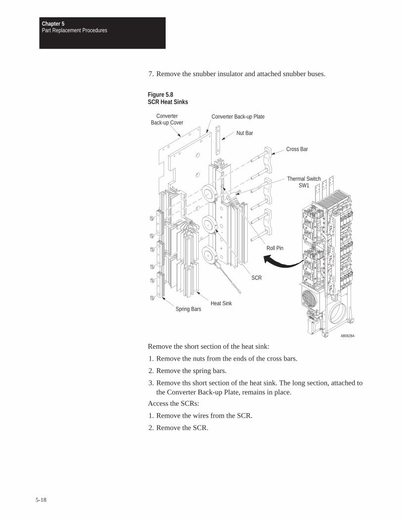
Chapter 5Part Replacement Procedures
5-18
7. Remove the snubber insulator and attached snubber buses.
Figure 5.8SCR Heat Sinks
AB0628A
Thermal SwitchSW1
Cross Bar
Roll Pin
SCR
Spring BarsHeat Sink
Converter Back-up Plate
Nut Bar
ConverterBack-up Cover
Remove the short section of the heat sink:
1. Remove the nuts from the ends of the cross bars.
2. Remove the spring bars.
3. Remove ths short section of the heat sink. The long section, attached tothe Converter Back-up Plate, remains in place.
Access the SCRs:
1. Remove the wires from the SCR.
2. Remove the SCR.

Chapter 5Part Replacement Procedures
5-19
Installation
1. Adjust the roll pins in each heat sink half to protrude 1.5 mm (0.060 in)toward the inside of the heat sink.
2. Apply silicone oil to the heat sink in the areas around the roll pins.
3. Clean the surface of the SCR and place it on the roll pin.
4. Apply silicone oil to the other side of the SCR.
5. Install the SCR Heat Sink in reverse order of removal. Leave access tothe SCR gate connections.
6. Attach the wires to the SCR.
IMPORTANT: Refer to the torque gauge on the spring bars on the leftside of the heat sink. Without load, the torque gauge should read zero. If itdoes not, replace the spring bar assembly. Refer to Chapter 3 –Disassembly and Access Procedures, Fastener Torque Specifications.
ATTENTION: Replace all guards before applying power to thedrive. Failure to replace guards may result in death or seriousinjury.

Chapter 5Part Replacement Procedures
5-20
Fan and Transformer Assembly
The two fans are located at the bottom of the Inverter Housing Assembly.The Fan Transformer and Fan Capacitors are located in the bottom leftcorner, attached to Fan 1. Both fans and the Transformer Assembly can bereplaced without pulling out the Inverter Housing Assembly.
Figure 5.9Fan and Transformer Assembly
AB0610A
Fan 1
Fan Cover
FanTransformer
FanCapacitor
Fan 2
Fan Cover

Chapter 5Part Replacement Procedures
5-21
Removal
ATTENTION: Disconnect and lock out power from the drivebefore disassembling the drive. Failure to disconnect power mayresult in death or serious injury. Verify bus voltage by measuringthe voltage between the Negative Capacitor Bus and both ends ofall three 350 amp fuses. An open fuse does not show voltage acrossboth ends of the fuse. Failure to measure voltage at both ends of thefuses may result in death or serious injury. Refer to Figure 3.5. Donot attempt to service the drive until the bus voltage has dischargedto zero volts.
ATTENTION: Hazard of electric shock exists. Up to 1,600 VDCwill be on Power Module Snubber Board Connector J1 if theSnubber Resistor is open. Measure for zero (0) VDC from SnubberBoard terminal TP3 to plus (+) bus before removing Connector J1.Use a resistor greater than 1 ohm and less than 100 ohm, rated for25 watts minimum, between TP3 and plus (+) bus to discharge anyvoltage. Refer to Chapter 3 – Disassembly and Access Procedures,Removing a Power Module Snubber Board.
ATTENTION: Wear a wrist-type grounding strap when servicing1336 PLUS Drives. Failure to protect drive components againstESD may damage drive components. Refer to ElectrostaticDischarge Precautions at the beginning of this chapter.
IMPORTANT: Before you remove connections and wires from the drivecomponents, mark the connections and wires to correspond with theircomponent connections and terminals to prevent incorrect wiring duringassembly.
1. Remove power from the drive.
2. Open the PC Board Mounting Frame.
3. Check for zero volts between +DC and –DC. Refer to Figure 3.5.
4. Check for the absence of control voltage at the points marked on theMain Control Board.

Chapter 5Part Replacement Procedures
5-22
Remove the Fan Transformer:
1. Remove the wiring harness to the Fan Transformer Assembly.
2. Turn the thumb latch, fastening the Transformer Assembly to Fan 1, 1/4turn counterclockwise.
3. Tilt the Transformer Assembly forward and lift it from the mountingbracket.
Remove Fan 1:
1. Disconnect the fan wiring harness.
2. Pull down on both spring pins fastening the fan to the Inverter HousingAssembly to remove the fan. Pull the fan toward you to remove it.
Remove Fan 2:
1. Disconnect the Fan wiring harness.
2. Remove the screws fastening the fan cover to the fan.
3. Turn the standoffs, fastening the fan to the Inverter Housing Assembly,1/4 turn counterclockwise to remove the fan.
InstallationInstall the Fan and Transformer Assembly in reverse order of removal.
ATTENTION: Replace all guards before applying power to thedrive. Failure to replace guards may result in death or seriousinjury.

Chapter 5Part Replacement Procedures
5-23
DC Bus Inductor
The DC Bus Inductor is located in the lower part of the Capacitor BankAssembly, behind the Terminal Strips and Motor Buses.
Figure 5.10DC Bus Inductor
AB0611B
DC BusInductor
InductorMounting Plate
Inductor PowerBus Connection
InductorFlex Cable
InductorFlex Bus
GroungSense CT

Chapter 5Part Replacement Procedures
5-24
Removal
ATTENTION: Disconnect and lock out power from the drivebefore disassembling the drive. Failure to disconnect power mayresult in death or serious injury. Verify bus voltage by measuringthe voltage between the Negative Capacitor Bus and both ends ofall three 350 amp fuses. An open fuse does not show voltage acrossboth ends of the fuse. Failure to measure voltage at both ends of thefuses may result in death or serious injury. Refer to Figure 3.5. Donot attempt to service the drive until the bus voltage has dischargedto zero volts.
ATTENTION: Wear a wrist-type grounding strap when servicing1336 PLUS Drives. Failure to protect drive components againstESD may damage drive components. Refer to ElectrostaticDischarge Precautions at the beginning of this chapter.
IMPORTANT: Before you remove connections and wires from the drivecomponents, mark the connections and wires to correspond with theircomponent connections and terminals to prevent incorrect wiring duringassembly.
1. Remove power from the drive.
2. Open the PC Board Mounting Frame.
3. Check for zero volts between +DC and –DC. Refer to Figure 3.5.
4. Check for the absence of control voltage at the points marked on theMain Control Board.
5. Access the Capacitor Bank Assembly. Refer to Chapter 3 – Disassemblyand Access Procedures, Access to the Capacitor Bank Assembly.
6. Remove the Inductor Flex Cable and the Ground Sense CT. Refer toRemoving the Ground Sense CT in this chapter.
7. Remove the Inductor Flex Bus.
8. Remove the two inductor power bus connections.
9. Remove the screws fastening the inductor to the Inductor MountingPlate.

Chapter 5Part Replacement Procedures
5-25
IMPORTANT: Note the position and orientation of the Ground Sense CT(CT3) around the (–)Bus terminal at the top of the DC Bus Inductor. TheGround Sense CT is removed with the inductor. Install the Ground SenseCT in the same position. Check that the (+)Bus cable to the fuse passesthrough the Ground Sense CT during assembly.
10. Remove the DC Bus Inductor from the drive.
Installation
Install the DC Bus Inductor in reverse order of removal. Refer toChapter 3 – Disassembly and Access Procedures, Fastener TorqueSpecifications.
ATTENTION: Replace all guards before applying power to thedrive. Failure to replace guards may result in death or seriousinjury.
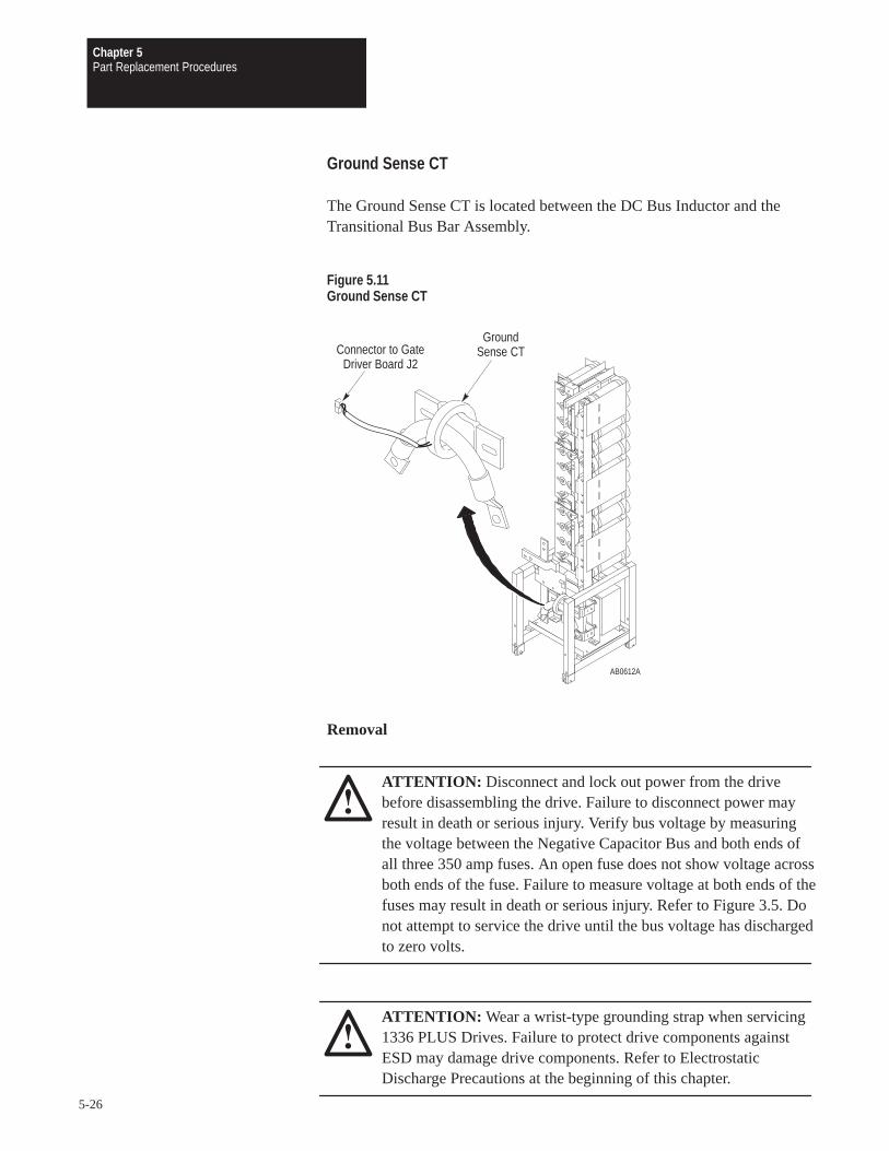
Chapter 5Part Replacement Procedures
5-26
Ground Sense CT
The Ground Sense CT is located between the DC Bus Inductor and theTransitional Bus Bar Assembly.
Figure 5.11Ground Sense CT
AB0612A
GroundSense CTConnector to Gate
Driver Board J2
Removal
ATTENTION: Disconnect and lock out power from the drivebefore disassembling the drive. Failure to disconnect power mayresult in death or serious injury. Verify bus voltage by measuringthe voltage between the Negative Capacitor Bus and both ends ofall three 350 amp fuses. An open fuse does not show voltage acrossboth ends of the fuse. Failure to measure voltage at both ends of thefuses may result in death or serious injury. Refer to Figure 3.5. Donot attempt to service the drive until the bus voltage has dischargedto zero volts.
ATTENTION: Wear a wrist-type grounding strap when servicing1336 PLUS Drives. Failure to protect drive components againstESD may damage drive components. Refer to ElectrostaticDischarge Precautions at the beginning of this chapter.
Chapter 5Part Replacement Procedures
5-27
IMPORTANT: Before you remove connections and wires from the drivecomponents, mark the connections and wires to correspond with theircomponent connections and terminals to prevent incorrect wiring duringassembly.
1. Remove power from the drive.
2. Open the PC Board Mounting Frame.
3. Check for zero volts between +DC and –DC. Refer to Figure 3.5.
4. Check for the absence of control voltage at the points marked on theMain Control Board.
5. Access the Capacitor Bank Assembly. Refer to Chapter 3 – Disassemblyand Access Procedures, Access to the Capacitor Bank Assembly.
6. Remove the Ground Sense CT connector J2 from the Gate DriverBoard.
7. Remove the nut and washers fastening the end of the Inductor FlexibleCable to the right-angled connector on the right side of the DC BusInductor.
8. Remove the Inductor Flex Cable from the right side inductor power busconnection.
9. Slide the Ground Sense CT from the Inductor Flex Cable.
InstallationInstall the Ground Sense CT in reverse order of removal, inserting theInductor Flex Cable through the center of the Ground Sense CT. Refer toChapter 3 – Disassembly and Access Procedures, Fastener TorqueSpecifications.
ATTENTION: A possible short-circuit hazard exists. Position thefuse-to-inductor wire with the shrink-wrapped end of the wireconnected to the DC Bus Inductor. Failure to position the wire asillustrated may result in serious injury or equipment damage.
ATTENTION: Replace all guards before applying power to thedrive. Failure to replace guards may result in death or seriousinjury.

Chapter 5Part Replacement Procedures
5-28
Bus Fuses
The Bus Fuses are located on the Transitional Bus Bar assembly.
Figure 5.12Bus Fuse
AB0613A
Bus Fuse
Removal
ATTENTION: Disconnect and lock out power from the drivebefore disassembling the drive. Failure to disconnect power mayresult in death or serious injury. Verify bus voltage by measuringthe voltage between the Negative Capacitor Bus and both ends ofall three 350 amp fuses. An open fuse does not show voltage acrossboth ends of the fuse. Failure to measure voltage at both ends of thefuses may result in death or serious injury. Refer to Figure 3.5. Donot attempt to service the drive until the bus voltage has dischargedto zero volts.
ATTENTION: Wear a wrist-type grounding strap when servicing1336 PLUS Drives. Failure to protect drive components againstESD may damage drive components. Refer to ElectrostaticDischarge Precautions at the beginning of this chapter.

Chapter 5Part Replacement Procedures
5-29
IMPORTANT: Before you remove connections and wires from the drivecomponents, mark the connections and wires to correspond with theircomponent connections and terminals to prevent incorrect wiring duringassembly.
Access the drive:
1. Remove power from the drive.
2. Open the PC Board Mounting Frame.
3. Check for zero volts between +DC and –DC. Refer to Figure 3.5.
4. Check for the absence of control voltage at the points marked on theMain Control Board.
5. Remove the nuts and washers fastening the Bus Fuse to the drive.
Installation
Install the Bus Fuse in reverse order of removal. Refer toChapter 3 – Disassembly and Access Procedures, Fastener TorqueSpecifications.
ATTENTION: Replace all guards before applying power to thedrive. Failure to replace guards may result in death or seriousinjury.
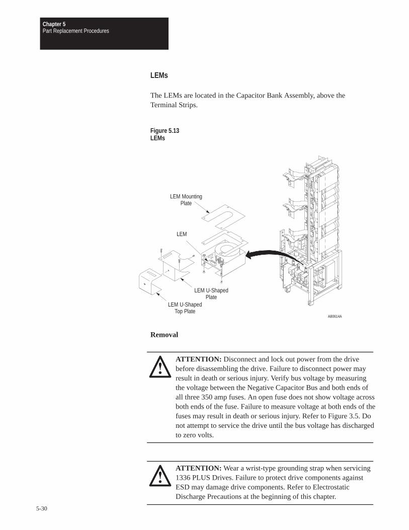
Chapter 5Part Replacement Procedures
5-30
LEMs
The LEMs are located in the Capacitor Bank Assembly, above theTerminal Strips.
Figure 5.13LEMs
AB0614A
LEM U-ShapedTop Plate
LEM U-ShapedPlate
LEM MountingPlate
LEM
Removal
ATTENTION: Disconnect and lock out power from the drivebefore disassembling the drive. Failure to disconnect power mayresult in death or serious injury. Verify bus voltage by measuringthe voltage between the Negative Capacitor Bus and both ends ofall three 350 amp fuses. An open fuse does not show voltage acrossboth ends of the fuse. Failure to measure voltage at both ends of thefuses may result in death or serious injury. Refer to Figure 3.5. Donot attempt to service the drive until the bus voltage has dischargedto zero volts.
ATTENTION: Wear a wrist-type grounding strap when servicing1336 PLUS Drives. Failure to protect drive components againstESD may damage drive components. Refer to ElectrostaticDischarge Precautions at the beginning of this chapter.

Chapter 5Part Replacement Procedures
5-31
IMPORTANT: Before you remove connections and wires from the drivecomponents, mark the connections and wires to correspond with theircomponent connections and terminals to prevent incorrect wiring duringassembly.
1. Access the Capacitor Bank Assembly. Refer to Chapter 3 – Disassemblyand Access Procedures, Access to the Capacitor Bank Assembly.
2. Remove the wires from the LEM connectors.
3. Remove the two screws fastening the LEM mounting plate to the LEM.
4. Remove the LEM U-shaped top plate and the LEM U-shaped plate.
5. Remove the screws and standoffs fastening the LEM to the assemblyframe.
6. Remove the Terminal Strip from the motor bus.
7. Disconnect the motor bus from the Motor Bus Support.
8. Disconnect the motor bus at its upper end.
9. Remove the motor bus and LEM from the Capacitor Bank Assemblyframe.
10. Remove the LEM from the motor bus.
Installation
Install the LEMs in reverse order of removal. Refer to Chapter 3 –Disassembly and Access Procedures, Fastener Torque Specifications.
ATTENTION: Replace all guards before applying power to thedrive. Failure to replace guards may result in death or seriousinjury.

Chapter 5Part Replacement Procedures
5-32
MOV Surge Suppressor
The MOV Surge Suppressor is located on the left side of the InverterHousing Assembly in the top-left corner at the back of the drive near thevertical bus bars.
The MOV protects the drive from high voltage surges above approximately1,000 volts. Replace it if it is burned, expanded, or ruptured after suchevents as a lightening strike, or inadvertent connection of the drive input toa voltage source substantially above nameplate voltage.
Figure 5.14MOV Surge Suppressor
AB0617A
MOV SurgeSuppressor
Removal
ATTENTION: Disconnect and lock out power from the drivebefore disassembling the drive. Failure to disconnect power mayresult in death or serious injury. Verify bus voltage by measuringthe voltage between the +DC and –DC on Terminal Block TB1. Donot attempt to service the drive until the bus voltage has dischargedto zero volts.

Chapter 5Part Replacement Procedures
5-33
ATTENTION: Hazard of electric shock exists. Up to 1,600 VDCwill be on Power Module Snubber Board Connector J1 if theSnubber Resistor is open. Measure for zero (0) VDC from SnubberBoard terminal TP3 to plus (+) bus before removing connector J1.Use a resistor greater than 1 ohm and less than 100 ohm, rated for25 watts minimum, between TP3 and plus (+) bus to discharge anyvoltage. Refer to Chapter 3 – Disassembly and Access Procedures,Removing a Power Module Snubber Board.
ATTENTION: Wear a wrist-type grounding strap when servicing1336 PLUS Drives. Failure to protect drive components againstESD may damage drive components. Refer to ElectrostaticDischarge Precautions at the beginning of this chapter.
IMPORTANT: Before you remove connections and wires from the drivecomponents, mark the connections and wires to correspond with theircomponent connections and terminals to prevent incorrect wiring duringassembly.
1. Access the Inverter Housing Assembly. Refer to Chapter 3 –Disassembly and Access Procedures, Access to the Inverter HousingAssembly.
2. Remove the MOV wire harness from the vertical bus bars on the left atthe back of the Inverter Housing Assembly.
3. Remove the screw fastening the MOV to the Inverter weldment.
InstallationInstall the MOV Surge Suppressor in reverse order of removal. Refer toChapter 3 – Disassembly and Access Procedures, Fastener TorqueSpecifications.
ATTENTION: Replace all guards before applying power to thedrive. Failure to replace guards may result in death or seriousinjury.

Chapter 5Part Replacement Procedures
5-34
This Page Intentionally Left Blank.
Chapter
6-1
Replacement Parts List
Chapter Objectives This chapter illustrates and lists replacement parts for the 1336 PLUSDrives rated B300 – B600, C300 – C600, and BX250, and describesreplacement parts ordering procedures.
The following illustration and table show you parts, part names, partnumbers, locations, and chapters for replacement procedures.
Ordering Replacement For your convenience, the Allen-Bradley Drives Division and the
Parts Allen-Bradley Support Division provide efficient and convenient repairand exchange for eligible equipment.
A product service report number is required to return any equipment forrepair. Your local Allen-Bradley distributor or area sales and support officecan provide you with a product service report number.
You should return equipment to be repaired to the area sales and supportcenter nearest you. Reference the product service report number on thecarton and packing slip. Include:
Your company name
Your company address
The repair purchase order number
A brief description of the problem
Contact your local Allen-Bradley distributor or sales office for a completelisting of area sales and support centers near you.
For parts catalog numbers, refer to the 1336 PLUS Spare Parts Pricingpublication included with your drive documentation set.

Chapter 6Replacement Parts List
6-2
Replacement Parts Listing
Figure 6.1Parts for B300 – B600, C300 – C600, and BX250 Drives
AB0626A
12
5
3
46 7
8
9
10
11
1213
14
15
16
17
18
19
20
21
22

Chapter 6Replacement Parts List
6-3
Table 6.AReplacement Parts for B300 – B600, C300 – C600, and BX250 Drives
Callout Symbol Description Location Replacement Procedures
1 MOV MOV Surge Suppressor Inverter Housing Assembly Chapter 5, MOV Surge Suppressor
2 Q11, Q12, Q21, Q22Q31, Q32, Q41, Q42Q51, Q52, Q61, Q62
Transistor (Power Module) Inverter Housing Assembly mainheat sink
Chapter 5, Power Modules
3 R20 – R25 Power Module Snubber Resistor Inverter Housing Assembly mainheat sink
Chapter 3, Removing a Power ModuleSnubber Board
4 A23 – A28 Power Module Gate InterfaceBoard
Power Module Chapter 5, Power Modules
5 NTC1 Thermistor Inverter Housing Assembly mainheat sink
Chapter 5, Thermistor
6 A20 – A22 Power Module Snubber Board Power Module Chapter 3, Removing a Power ModuleSnubber Board
7 R1 – R9 Load-Sharing Resistor Capacitor Bank Assembly Chapter 5, Bus Capacitor Bank
8 C1 – C36 Bus Capacitors Capacitor Bank Assembly Chapter 5, Bus Capacitor Bank
9 L1 DC Bus Inductor Capacitor Bank Assembly Chapter 5, DC Bus Inductor
10 CT3 Ground Sense CT Capacitor Bank Assembly Chapter 5, Ground Sense CT
11 CT1, CT2 LEM Capacitor Bank Assembly Chapter 5, LEMs
12 F1 – F3 Bus Fuse, 350 amp Capacitor Bank Assembly Chapter 5, Bus Fuses
13 THS1 Thermal Switch SW1 Inverter Housing Assembly,upper SCR heat sink
Chapter 5, SCRs
14 FAN 1 Fan 1 Inverter Housing Assembly Chapter 5, Fan and Transformer Assembly
15 T1 Fan Transformer Inverter Housing Assembly Chapter 5, Fan and Transformer Assembly
16 C38, C39 Fan Capacitor Inverter Housing Assembly Chapter 5, Fan and Transformer Assembly
17 FAN 2 Fan 2 Inverter Housing Assembly Chapter 5, Fan and Transformer Assembly
18 SCR1 – SCR6 SCR Inverter Housing Assembly, SCRheat sinks
Chapter 5, SCRs
19 A11 – A13 Input Rectifier Snubber Board Inverter Housing Assembly, SCRheat sinks
Chapter 3, Removing the Input RectifierSnubber Board
20 A1 Gate Driver Board PC Board Mounting Frame Chapter 3, Removing the Gate Driver Board
21 A10 Precharge Board PC Board Mounting Frame Chapter 3, Removing the Precharge Board
22 MAIN CTL Main Control Board PC Board Mounting Frame Chapter 3, Removing the Main ControlBoard

Chapter 6
Spare Parts Information
1336 PLUSSpare Parts Information
Current 1336 PLUS spare parts information including recommended parts, catalog numbers and pricing can be obtrained from the following sources:
• Allen-Bradley home page on the World Wide Web at:http://www.ab.comthen select . . .“Drives” followed by . . .“Product Information” and . . .“Service Information . . .”Select document 1060.pdf
• Standard Drives “AutoFax” service — An automated system that you can call to request a “faxed” copy of the spare parts information (or other technical document).
Simply call 440-646-6701 and follow the phone prompts to request document 1060.

C300 – 600B300 – B6001336 PLUS Schematics
BX250
S-1
300 – 600 HP 1336 PLUS Drives


C300 – C600B300 – B6001336 PLUS Schematics
BX250
S-6
Current and Voltage Processing PWM Algorithm Analog I/O Fault Protection and Monitoring
Main Control Board
TB21
Analog Out
Contacts Shownin Unpowered State
10k Ohm
4–20mAtoTE or PE
0–10VPulse
SourceAuxiliary Output
forDynamic BrakeSlave Operation
CR2
TETE
CR1ChassisCommon
Only Presenton 5.5–22 kW(7.5–30 HP)
Only Presenton 5.5–22 kW(7.5–30 HP)
CR3CR3 CR4CR4
2 3 4 5 6 9 10 11 12 13 14 15 16 17 18 A1 A287
User SuppliedAnalog Device
++ + +
36 18 1213 101617 141527 22 19202526 232430 29 283435 323345 3840 39 37
44 43 42474849 4650 41 31 1121 89 57 6 134 2
J6
J8
J9Optional SCANportCommunicationsAdapter Ports
J2
J7
J10
J1
20
20
AB0735A
From NTCFrom Gate Driver BoardConnector J1

Glossary
G-1
Glossary
AC Contactor: An alternating-current (AC) contactor is designed for thespecific purpose of establishing or interrupting an AC Power circuit.
Adjustable Speed: The concept of varying the speed of a motor, eithermanually or automatically. The desired operating speed (set speed) isrelatively constant regardless of load.
Adjustable Speed Drive (Electrical): The adjustable speed drive iscomprised of the motor, drive controller and operator’s controls (eithermanual or automatic).
Ambient Temperature: The temperature of the medium (air, water, earth)into which the heat of the equipment is dissipated.
Base Speed:The manufacturer’s nameplate rating where the motor willdevelop rated power at rated load and voltage. With DC drives, it iscommonly the point where full armature voltage is applied with full-ratedfield excitation. With AC systems, it is commonly the point where 60 Hz isapplied to the induction motor.
BR: Refer to Bridge Rectifier.
Braking: A method of stopping or reducing the time required to stop anAC motor, and can be accomplished in several ways:
1. DC-Injection braking (AC drives) A method which produceselectromagnetic braking forces in the motor by removing 2 AC motor(stator) phases and injecting DC current. The result is a linear brakingcharacteristic (ramp) that does not diminish with motor speed.Application is normally limited to 10–20% of rated motor speed due toincreased heating in the rotor.
2. Dynamic braking (AC drives) A method which produceselectromagnetic braking forces in the motor by dissipating generatedpower into the DC bus through a resistive load. Braking force remainsconstant and is only limited by the thermal capacity of the resistors. Theresult is a linear braking characteristic (ramp) that does not diminishwith motor speed.
3. Regenerative braking A method which produces electromagneticbraking forces in the motor by electronically controlling the return ofgenerated power to the AC supply. The result is a controllable linearbraking characteristic (ramp) that does not diminish with motor speed.
Glossary
G-2
4. Motor-mounted or separately-mounted brake A positive-action,mechanical friction device. Normal configuration is such that when thepower is removed, the brake is set. This can be used as a holding brake.(Note: A separately mounted brake is not one which is located on somepart of the mechanical drive train other that the motor.)
Breakaway Torque: The torque required to start a machine fromstandstill. Breakaway torque is always greater than the torque needed tomaintain motion.
Breakdown Torque: The breakdown torque of an AC motor is themaximum torque which it will develop with rated voltage applied at ratedfrequency.
Bridge Rectifier (Diode, SCR): A non-controlled, full-wave rectifier thatproduces a constant, rectified, DC voltage. An SCR bridge rectifier is afull-wave rectifier with a DC output that can be controlled by switching onthe gate control element.
Bridge Rectifier: A full-wave rectifier that conducts current in only onedirection of the input current. AC applied to the input results inapproximate DC at the output.
British Thermal Unit (BTU): The quantity of heat required to raise onepound of water by one degree Fahrenheit.
BTU: Refer to British Thermal Unit.
Bus: A single path or multiple parallel paths for power or data signals towhich several devices may be connected at the same time. A bus may haveseveral sources of supply and/or several sources of demand.
Bus Sense:A signal transducer that generates a signal proportional to thecurrent in the drive’s DC bus. The control logic uses this signal to sense thepresence or absence of bus voltage.
CEMF: Refer to Counter Electromotive Force.
CMOS: Complimentary Metallic Oxide Semiconductor. A semiconductordevice in which an electric field controls the conductance of a channelunder a metal electrode called a gate.
Cogging: A condition in which a motor does not rotate smoothly but stepsor jerks from one position to another during shaft revolution. Cogging is

Glossary
G-3
most pronounced at low motor speeds and can cause objectionablevibrations in the driven machinery.
Constant Torque Range: A speed range in which a motor is capable ofdelivering a constant torque, subject to cooling limitations of the motor.
Constant Voltage Range:(AC Drives) The range of motor operationwhere the drive’s output voltage is held constant as output frequency isvaried. This speed range produces motor performance similar to a DCdrive’s constant horsepower range.
Constant Volts per Hertz (V/Hz): The V/Hz relationship exists in ACdrives where the output voltage is directly proportional to frequency. Thistype of operation produces constant rated torque as the motor’s speedvaries.
Continuous Duty (CONT): A motor that can continue to operate withoutstopping and remain within the insulation temperature limits after it hasreached normal operating (equilibrium) temperature.
Converter:
1. A device for changing AC to DC. This is accomplished through use of adiode rectifier or thyristor rectifier circuit.
2. A device for changing AC to DC to AC (e.g., adjustable frequencydrive). A frequency converter, such as that found in an adjustablefrequency drive, consists of a rectifier, a DC intermediate circuit, aninverter, and a control unit.
Counter Electromotive Force (CEMF): The product of a motor armaturerotating in a magnetic field. This generating action takes place whenever amotor is rotating. Under stable motoring conditions the generated voltage(CEMF) is equal to the voltage supplied to the motor minus small losses.However, the polarity of the CEMF is opposite to that of the power beingsupplied to the armature.
Current Limiting: An electronic method of limiting the maximumcurrent available to the motor. This is adjustable so that the motor’smaximum current can be controlled. It can also be preset as a protectivedevice to protect both the motor and the control from extended overloads.
DC Boost: Compensates for the voltage drop across the resistance of anAC motor circuit and the resulting reduction in torque.
DC Bus: A drive’s power structure that transmits a rectified AC linepower from the bridge rectifier to the output transistors.

Glossary
G-4
DC Hold: Describes a “holding brake” function to stop motor rotationafter a ramp-to-stop function is activated.
Diode: A solid-state uni-directional conductor.
Drift: A slow change in some characteristic of a device. For a drive, it isthe deviation from the initial set speed with no load change over a specifictime period. Normally the drive must be operated for a specified warm-uptime at a specified ambient temperature before drift specifications apply.Drift is normally caused by random changes in operating characteristics ofvarious control components.
Drive Controller (Variable Speed Drive) (Drive): An electronic devicethat can control the speed, torque, horsepower, and direction of an AC orDC motor.
1. PWM drive is a motor drive using pulse-width modulationtechniques to control power to the motor. A high-efficiency drive usedfor high-response applications.
2. SCR drive is a motor drive that uses SCRs as the power controlelements. Usually used for low-bandwidth high-power applications.
3. Servo drive is a motor drive that uses internal feedback loops formotor current and/or velocity.
4. Vector drive is an AC static motor drive using power-controltechniques that produce motor performance similar to DC static drives.
Duty Cycle:
1. The ratio of working time to total time for an intermittently operatingdevice. Usually expressed as a percentage.
2. The ratio of pulse width to the interval between like portions ofsuccessive pulses. Usually expressed as a percentage.
Dynamic Braking: Refer to Braking.
Efficiency: Ratio of output to input, indicated by a percentage. In amotor, it is the effectiveness with which the motor converts electricalenergy into mechanical energy. In a power supply, it is the effectivenesswith which the power supply converts AC power into DC power.
Electrostatic Discharge (ESD):A static-electricity discharge that maydamage drive components. Refer to the ESD precautions found in thismanual to guard against damage to drive components.

Glossary
G-5
Enable: To activate logic by the removal of a suppression signal.
Enclosure: The housing in which equipment is mounted. They areavailable in designs for various environmental conditions. Refer to NEMAstandard for specifications of different types of enclosures.
ENUM (Enumeration): An ANSI C standard extension to the C language.An ENUM is a set of named integer constants that specify all the legalvalues a variable of a given type may have. The keyword ENUM signalsthe start of an enumeration type.
ESD: Refer to Electrostatic Discharge.
Floating Ground: An electrical circuit common which is not at earthground potential or the same ground potential as circuitry with which itinterfaces. A voltage difference can exist between the floating ground andearth ground.
Force: The tendency to change the motion of an object with an exertion ofenergy from a separate source.
Full Load Torque: The full-load torque of a motor is the torque necessaryto produce rated horsepower at full-load speed.
Gate:
1. A logic element that blocks or passes a signal, depending on the statusof specified input signals.
2. The control element of an SCR.
GND Sense:A current transducer that detects an unequal or imbalancedcurrent in the three-phase AC line or DC bus of the drive. The imbalanceindicates an output ground fault condition.
Horsepower (hp): A unit of power: 1 hp = 33,000 ft-lb/min. = 746 watts.
IEC: International Electrotechnical Commission.
IGBT: Refer to Insulated Gate Bipolar Transistor.
Induction Motor: An induction motor is an alternating-current motor inwhich the primary winding on one member is connected to the powersource. A secondary winding on the other member carries the inducedcurrent. There is no physical electrical connection to the secondarywinding; its current is induced.

Glossary
G-6
Inertia: A measure of a body’s resistance to change in velocity, whether abody is at rest or moving at a constant velocity. The velocity can be eitherlinear or rotational. The moment of inertia (WK2) is the product of theweight (W) of an object and the square of the radius of gyration (K2). Theradius of gyration is a measure of how the mass of the object is distributedabout the axis of rotation. WK2 is usually expressed in units of lb-ft2.
Insulated Gate Bipolar Transistor (IGBT): A type of transistorcommonly used in drive-control devices.
Integral-Horsepower Motor: A motor that has a continuous rating of1 hp or more, built into a frame.
International Organization for Standards (ISO): An organizationestablished to promote development of international standards.
Interposing Relay: An interposing relay is a relay that accepts controlsignals of one logic level in order to provide isolated contact signals in acircuit operating at a different logic level.
Inverter:
1. An AC adjustable frequency drive.
2. A particular section of an AC drive. This section uses the DC voltagefrom a previous circuit stage (intermediate DC circuit) to produce apulse-width-modulated or stepped AC current or voltage waveform thathas characteristics similar to the desired sine-wave frequency.
3. A circuit whose output signal is the inverse of its input (a positive-goingpulse is inverted to a negative-going pulse, and vise versa).
ISO: Refer to International Organization for Standards.
Isolation Transformer:
1. A transformer that provides DC isolation from other equipment notconnected to that transformer secondary.
2. A transformer that provides noise isolation between the primary andsecondary by such means as a Faraday shield.
Jogging:
1. In a numerical control system, an operator manually generating motion(continuously or incrementally) by closing a switch.
2. An operator generating motion by closing a switch.
Kinetic Energy: The energy of motion of a moving body.
Glossary
G-7
LAD: Refer to Linear Acceleration/Deceleration.
LEM: A hall-effect current transducer that senses drive output current andgenerates a signal for the control logic.
Linear Acceleration/Deceleration (LAD): A circuit that controls the rateat which a motor is allowed to accelerate to a set speed or decelerate tozero speed. On most drives, this circuit is adjustable and can be set toaccommodate a particular application.
Linearity: A measure of how closely a characteristic follows astraight-line function.
Locked-Rotor Current: Steady-state current taken from the line currentwith the a rotor at standstill (at rated voltage and frequency). This is thecurrent when starting the motor and load.
Locked-Rotor Torque: The minimum torque that a motor will develop atrest for all angular positions of the rotor (with rated voltage applied at ratedfrequency).
Meggar Test: A test used to measure an insulation system’s resistance.This is usually measured in megohms by applying a high voltage.
MOV: Refer to Surge Protection.
National Electrical Code (NEC): A set of regulations governing theconstruction and installation of electrical wiring and apparatus, establishedby the National Fire Protection Association and suitable for mandatoryapplication by governing bodies exercising legal jurisdiction. It is widelyused by state and local authorities within the United States.
National Electrical Manufacturer’s Association (NEMA): A non-profitorganization organized and supported by electrical equipment and supplymanufacturers. Some NEMA motor standards include horsepower (hp)ratings, speeds, frame sizes and dimensions, torques, and drive enclosures.
NEC: Refer to National Electrical Code.
Negative Slope: The location on a V/Hz curve where the break voltageexceeds the base voltage.
NEMA: Refer to National Electrical Manufacturer’s Association.

Glossary
G-8
Offset: The steady-state deviation of a controlled variable from a fixedsetpoint.
Op Amp: An operational amplifier. A high-gain stable linear DCamplifier that is designed to be used with external circuit elements.
Open Loop System:A control system that has no means of comparing theoutput with the input for control purposes.
Overload Capacity: The ability of the drive to withstand currents beyondthe system’s continuous rating. It is normally specified as a percentage offull-load current endured for a specified time period. Overload capacity isdefined by NEMA as 150% of rated full load current for one minute for“standard industrial DC motors.”
PC:
1. Personal Computer.
2. Programmable Controller.
3. Printed Circuit.
Plugging: A type of motor braking provided by reversing either linevoltage polarity or phase sequence so that the motor develops a countertorque that exerts a retarding force to brake the motor.
Pot: A potentiometer, or variable resistor.
Power: Work done per unit of time. Measured in horsepower (hp) orwatts (W): 1 hp = 33,000 ft-lb/min. = 746 W.
Power Factor (Displacement):A measurement of the time phasedifference between the fundamental voltage and fundamental current in anAC circuit. It represents the cosine of the phase angle difference. Fp = cos (α– β)
Power Factor (Distortion): A measurement of the ratio of the real power(kW) to the apparent power (kVA). Distortion power factor takes intoaccount harmonic voltage and current distortion as well asvoltage-to-current displacement.
Preform: A flexible material used between an electronic component andthe heat sink to which the component is attached. Preform providesmaximum heat dissipation from the component to the heat sink.

Glossary
G-9
Preset Speed:Describes one or more fixed speeds at which a driveoperates.
Programmable Controller: A solid-state control system that has auser-programmable memory for storage of instructions to implementspecific functions such as I/O control, logic, timing, counting, reportgeneration, communication, arithmetic, and data file manipulation. Acontroller consists of a central processor, input/output interface, andmemory. A controller is designed as an industrial control system.
Pull-In Torque: The maximum constant torque to which a synchronousmotor accelerates into synchronism at rated voltage and frequency.
Pull-Out Torque: The maximum running torque of a synchronous motor.
Pull-Up Torque: The torque required to accelerate the load from standstillto full speed (where breakdown torque occurs), expressed in percent ofrunning torque. It is the torque required not only to overcome friction,windage, and product loading but also to overcome the inertia of themachine. The torque required by a machine may not be constant after themachine has started to turn. This load type is characteristic of fans,centrifugal pumps, and certain machine tools.
PWM: Pulse-width Modulation. A technique used to eliminate or reduceunwanted harmonic frequencies when inverting DC voltage to sine waveAC.
Reactance: Pure inductance or capacitance, expressed in ohms, in acircuit. It is the component of impedance to alternating current that is notresistance.
Rectifier: A device that conducts current in only one direction, therebytransforming alternating current to direct current.
Regeneration: (AC drives) When the rotor synchronous frequency isgreater than the applied frequency.
Regenerative Braking: Slows or stops a motor through regeneration.Refer to Regeneration and Braking.

Glossary
G-10
Resolution: The smallest distinguishable increment into which a quantitycan be divided (e.g., position or shaft speed). It is also the degree to whichnearly equal values of a quantity can be discriminated. For rotary encoders,it is the number of unique electrically identified positions occurring in 360degrees of input shaft rotation. For D/A or A/D conversion, may beexpressed as the number of bits in the digital value that corresponds to afull-scale analog value.
SCR: Silicon Controlled Rectifier. A solid-state uni-directional latchingswitch.
Service Factor: When used on a motor nameplate, a number that indicateshow much above the nameplate rating a motor can be loaded withoutcausing serious degradation (i.e., a motor with 1.15 S-F can produce 15%greater torque than one with 1.0 S-F).
Set Speed:The desired operating speed.
Shock Load: The load seen by a clutch, brake, or motor in a system thattransmits high peak loads. This type of load is present in crushers,separators, grinders, conveyors, winches, and cranes.
Slip: The difference between rotating magnetic field speed (synchronousspeed) and rotor speed of AC induction motors. Usually expressed as apercentage of synchronous speed.
Slip Compensation: Monitors motor current and compensates for speedlost due to increased motor slip. The amount of slip is proportional to themotor load.
Speed Range:The speed minimum and maximum at which a motor mustoperate under constant or variable torque load conditions. A 50:1 speedrange for a motor with top speed 1800 rpm means the motor must operateas low as 36 rpm and still remain within regulation specification.Controllers are capable of wider controllable speed ranges than motorsbecause there is no thermal limitation, only electrical. Controllable speedrange of a motor is limited by the ability to deliver 100% torque belowbase speed without additional cooling.
Glossary
G-11
Speed Regulation:The numerical measure (percent) of how accuratelythe motor speed can be maintained. It is the percentage of change in speedbetween full load and no load. The ability of a drive to operate a motor atconstant speed (under varying load), without “hunting” (alternatelyspeeding up and slowing down). It is related to both the characteristics ofthe load being driven and electrical time constants in the drive regulatorcircuits.
Surge Protection: The process of absorbing and clipping voltagetransients on an incoming AC power line or control circuit. Surgeprotectors include MOVs (Metal Oxide Varistors) and specially designedR-C networks.
Synchronous Speed:The speed of an AC induction motor’s rotatingmagnetic field. It is determined by the frequency applied to the stator andthe number of magnetic poles present in each phase of the stator windings.Mathematically, it is expressed as: Sync Speed (rpm) = 120 x AppliedFreq. (Hz) / Number of poles per phase.
Torque: A turning force applied to a shaft, tending to cause rotation.Torque is equal to the force applied, times the radius through which it acts.Torque is measured in pound-feet, ounce-inches, Newton-meters, orgram-centimeters.
Transducer: A device that converts one energy form to another (e.g.,mechanical to electrical). When a transducer is actuated by signals fromone system or medium, it can supply a related signal to the other system ormedium.
Transient: A momentary power deviation in an electrical or mechanicalsystem.
Transistor: An active solid-state semiconductor device.
Work: A force moving an object over a distance. (work = force x distance)

Glossary
G-12
This Page Intentionally Left Blank.

Index
I-1
IndexA
Adapter Locations, 1-9
Adptr Freq Err, 2-4
Audience for this Manual, P-1
Auxiliary Fault, 2-4
Auxiliary Input, Definition, P-10
Auxiliary Interlock, Definition, P-10
BBGND 10ms Over, 2-4
Bit, Definition, P-10
Blwn Fuse Flt, 2-4
Bus Capacitor BankIllustration, 5-5Installation, 5-7Load-Sharing Resistors, 5-7Removal, 5-6Replacement, 5-5
Bus Capacitors, Testing, 4-12
Bus FuseIllustration, 5-28Installation, 5-29Removal, 5-28Replacement, 5-28
CCapacitor Bank Assembly, 3-22
Access to, 3-32Installation, 3-34Removal, 3-33
Capacitors. See Bus Capacitor Bank
Check, Definition, P-10
Clearing Faults, 2-15
Component Test Procedures, 4-1
Connector, Definition, P-10
Contact Description, 2-3
Control Interface BoardInstallation, 3-10
Removal, 3-9
Control Interface Board Jumpers, 1-3Jumper Locations, 1-3
Control Interface Board, Definition, P-11
Control Interface Option, 1-2
Control Logic Wiring, 1-1
Control Logic Wiring and Adapters, 1-1
Conventions, P-10
DDC Bus Inductor
Illustration, 5-23Installation, 5-25Removal, 5-24Replacement, 5-23
DC Voltage Check, Illustration, 3-8
Default, Definition, P-11
Detailed Product Identification, 5-3
Diag C Lim Flt, 2-4
Diagnostic ProceduresClearing Faults, 2-15Drive Goes to Max Frequency, 2-15Drive Stays at Zero Hertz, 2-14Drive Will Not Jog, 2-13Drive Will Not Start, 2-11No Display, 2-12
Disassembly and Access Procedures, 3-1Tools required, 3-2
Drive, Identification, P-5
Drive –> HIM, 2-4
Drive Components, Main, 5-4
Drive EnclosureClosing, 3-8Illustration, 3-6Opening, 3-7
Drive Fault Reset, 2-4
Drive Goes to Max Frequency, 2-15
Drive Rating Qualifications, P-9
Drive Stays at Zero Hertz, 2-14
Drive Will Not Jog, 2-13
Drive Will Not Start, 2-11

Index
I-2
EEE Init Read, 2-4
EE Init Value, 2-4
EEprom Checksum, 2-4
EEProm Fault, 2-4
Electrostatic Discharge, P-2
Electrostatic Discharge Precautions, P-2, 2-2
Enable Input, Definition, P-11
Enclosure Type, P-9
Error Codes, 2-4
ESD, P-2
FFalse, Definition, P-11
Fan and Transformer AssemblyIllustration, 5-20Installation, 5-22Removal, 5-21Replacement, 5-20
Fan Capacitors, 5-20
Fan Transformer, 5-20
Fastener Torque Specifications, 3-3
Fault Descriptions, 2-4
Fault Display, Illustration, 2-3
FaultsClearing, 2-15Cross Reference, 2-9Descriptions, 2-4
Fgnd 10ms Over, 2-4
GGate Driver Board
Illustration, 3-16Installation, 3-18Removal, 3-16Testing, 4-3
Ground Fault, 2-4
Ground Sense CTIllustration, 5-26Installation, 5-27Removal, 5-26Replacement, 5-26
Ground Warning, 2-5
HHertz Err Fault, 2-5
Hertz Sel Fault, 2-5
High Voltage Guard, 3-20Illustration, 3-19
HIM. See Human Interface Module
HIM –> Drive, 2-5
Human Interface Module (HIM)Description, 1-8Illustration, 1-9Operation, 1-10Removal, 1-10
IInput Mode, 1-5
Factory Default, 1-6Three-Wire Control, Multi-Source Reversing, 1-7Three-Wire Control, Single-Source Reversing, 1-6Two-Wire Control, Single-Source Control, 1-7
Input Rectifier Snubber BoardIllustration, 3-38Installation, 3-39Removal, 3-39
Inputs, Available, 1-4
Inverter Housing and Capacitor Bank Assemblies, Accessto, 3-21
Inverter Housing Assembly, 3-22Access to, 3-23Installation, 3-28Removal, 3-24
JJumper, Definition, P-11
LLanguage Modules, P-7
LEMsIllustration, 5-30Installation, 5-31

Index
I-3
Removal, 5-30Replacement, 5-30
Load Sharing Resistor Connections, 5-7
Local Programming, 1-4
Loop Overrn Flt, 2-5
MMain Control Board
Illustration, 3-14Installation, 3-16Removal, 3-14
Main Control Board Mounting Plate, 3-11Illustration, 3-11Installation, 3-13Removal, 3-12
Major Component Replacement. See Procedures
ManualAudience, P-1Objective, P-1
Max Retries Fault, 2-5
Motor Mode Flt, 2-5
Motor Stall Fault, 2-5
MountingFour-Point, 3-4Six-Point, 3-4Two-Point, 3-3
MOV Surge SuppressorIllustration, 5-32Installation, 5-33Removal, 5-32Replacement, 5-32
NNameplate Location, P-3
Neg Slope Fault, 2-6
No Display, 2-12
OOp Error Fault, 2-6
Open Pot Fault, 2-6
OptionControl Interface, 1-2
Identification, P-5
Options, P-7
Overcurrent Flt, 2-6
Overload Fault, 2-6
Overtemp Fault, 2-6
Overvolt Fault, 2-6
PP Jump Err Flt, 2-6
Parameter, Definition, P-11
Part Replacement Procedures, 5-1
PC Board Mounting Frame, 3-6, 3-22Illustration, 3-30Installation, 3-31Removal, 3-31
Phase U Fault, 2-6
Phase V Fault, 2-6
Phase W Fault, 2-6
Pole Calc Fault, 2-7
Power Loss Fault, 2-7
Power Mode Fault, 2-7
Power Module Snubber BoardIllustration, 3-35Installation, 3-37Removal, 3-36
Power Module Snubber ResistorIllustration, 5-14Installation, 5-15Removal, 5-15
Power ModulesIllustration, 4-9, 5-11Installation, 5-13Removal, 5-12Testing, 4-9
Power Overload, 2-7
Power Test Flt, 2-7
PrecautionsElectrostatic Discharge, P-2Safety, P-1
Precharge BoardIllustration, 3-19Installation, 3-21Removal, 3-19Testing, 4-7
Precharge Fault, 2-7

Index
I-4
Precharge Open, 2-7
Press, Definition, P-11
ProceduresBus Capacitor Bank Installation, 5-7Bus Capacitor Bank Removal, 5-6Bus Capacitor Replacement, 4-12Bus Capacitor Testing, 4-12Bus Fuse Installation, 5-29Bus Fuse Removal, 5-28Bus Fuse Replacement, 5-28Capacitor Bank Assembly Installation, 3-34Capacitor Bank Assembly Removal, 3-33Closing Drive Enclosure, 3-8Component Test, 4-1Control Interface Board Installation, 3-10Control Interface Board Removal, 3-9DC Bus Inductor Installation, 5-25DC Bus Inductor Removal, 5-24DC Bus Inductor Replacement, 5-23DC Voltage Check, 3-8Diagnostic, 2-11Drive Enclosure, Opening and Closing, 3-6Fan Installation, 5-22Fan Removal, 5-21Gate Driver Board Installation, 3-18Gate Driver Board Removal, 3-16Gate Driver Board Testing, 4-3Ground Sense CT Installation, 5-27Ground Sense CT Replacement, 5-26Input Rectifier Snubber Board Installation, 3-39Input Rectifier Snubber Board Removal, 3-39Inverter Housing Assembly, Access to, 3-23Inverter Housing Assembly, Installation, 3-28Inverter Housing Assembly, Removal, 3-24LEM Installation, 5-31LEM Removal, 5-30LEM Replacement, 5-30Main Control Board Installation, 3-16Main Control Board Mounting Plate Installation, 3-13Main Control Board Mounting Plate Removal, 3-12Main Control Board Removal, 3-14Major Component Replacement, 5-3MOV Surge Suppressor Installation, 5-33MOV Surge Suppressor Removal, 5-32MOV Surge Suppressor Replacement, 5-32Opening Drive Enclosure, 3-7Part Replacement, 5-1PC Board Mounting Frame Installation, 3-31PC Board Mounting Frame Removal, 3-30Power Module Installation, 5-13Power Module Removal, 5-12Power Module Replacement, 4-9Power Module Snubber Board Installation, 3-37Power Module Snubber Board Removal, 3-36
Power Module Snubber Resistor Installation, 5-15Power Module Snubber Resistor Removal, 5-15Power Module Testing, 4-9Precharge Board Installation, 3-21Precharge Board Removal, 3-19Precharge Board Testing, 4-7SCR Installation, 5-19SCR Removal, 5-17SCR Replacement, 4-15SCR Testing, 4-15Spine, Disconnecting, 3-26Spine, Installation, 3-28Spine, Removing, 3-27Thermistor Installation, 5-10Thermistor Removal, 5-9
Product Identification, P-3
ProgrammingInput Mode, 1-4Local, 1-4
RRelated Publications, P-12
Replacement PartsList, 6-1Ordering, 6-1
Reprogram Fault, 2-7
ROM or RAM Flt, 2-7
Run Boost Fault, 2-7
SSafety Precautions, P-1
Schematics, S-1
SCRsHeat Sinks, 5-18Illustration, 5-16Installation, 5-19Location, 5-16Removal, 5-17Replacement, 5-16Roll Pins, 5-19Spring Bars, 5-19Testing, 4-15
Serial Fault, 2-7
Service Platform, 3-29
Shear Pin Fault, 2-7
Software Compatibility, P-4
Speed Select, Input State, 1-8
Index
I-5
SpineDisconnecting, 3-26Installation, 3-28Removing, 3-27
TTB3 Terminal Designations, 1-5
Temp Sense Open, 2-8
Terminal Block Locations, 1-2
Terminal Designations, TB3, 1-5
Thermal Switch, 5-18
ThermistorIllustration, 5-8Installation, 5-10Removal, 5-9Replacement, 5-8
Torque Sequence, 3-3Four-Point Mounting, 3-4Six-Point Mounting, 3-4Two-Point Mounting, 3-3
Torque Specifications, 3-4
Transformer Assembly. See Fan and Transformer Assembly
TroubleshootingFault Code Cross Reference, 2-9Fault Descriptions, 2-4Fault Display Illustration, 2-3
Meter for, 2-1Overview, 2-1
Troubleshooting and Error Codes, 2-1
True, Definition, P-12
UUndervolt Fault, 2-8
UV Short Fault, 2-8
UW Short Fault, 2-8
VVW Short Fault, 2-8
WWire Sizes, 1-5
XXsistr Desat Flt, 2-8
ZZener Diode Testing, 4-5

Index
I-6
This Page Intentionally Left Blank

Notes
N-1

Notes
N-2

Notes
N-3

Notes
N-4

Notes
N-5

Notes
N-6

Notes
N-7

Notes
N-8

Notes
N-9

Notes
N-10

Notes
N-11

Notes
N-12

CU
T AL
ON
G D
OTT
ED L
INE
We Want Our Manuals to be the Best!
You can help! Our manuals must meet the needs of you, the user. This is your opportunity to make sure they do just that.By filling out this form you can help us provide the most useful, thorough, and accurate manuals available. Please take afew minutes to tell us what you think. Then mail this form, FAX it, or send comments via E-Mail.FAX: to your local Allen-Bradley Sales Office or 414/242-8579E-Mail: via Internet to: [email protected]
PUBLICATION NAME
PUBLICATION NUMBER, DATE AND PART NUMBER (IF PRESENT)
CHECK THE FUNCTION THAT MOST CLEARLY DESCRIBES YOUR JOB.
SUGGEST / RESPONSIBLE FOR THE PURCHASE OF EQUIPMENT MAINTAIN / OPERATE PROGRAMMABLE MACHINERY
DESIGN / IMPLEMENT ELECTRICAL SYSTEMS TRAIN/EDUCATE MACHINE USERS
SUPERVISE FLOOR OPERATIONS
WHAT LEVEL OF EXPERIENCE DO YOU HAVE WITH EACH OF THE FOLLOWING PRODUCTS?
NONE LITTLE MODERATE EXTENSIVE
PROGRAMMABLE CONTROL
AC / DC DRIVES
PERSONAL COMPUTERS
NC / CNC CONTROLS
DATA COMMUNICATIONS / LAN
RATE THE OVERALL QUALITY OF THIS MANUAL BY CIRCLING YOUR RESPONSE BELOW. (1) = POOR (5) = EXCELLENT
HELPFULNESS OF INDEX / TABLE OF CONTENTS 1 2 3 4 5
CLARITY 1 2 3 4 5
EASE OF USE 1 2 3 4 5
ACCURACY AND COMPLETENESS 1 2 3 4 5
QUALITY COMPARED TO OTHER COMPANIES’ MANUALS 1 2 3 4 5
QUALITY COMPARED TO OTHER ALLEN-BRADLEY MANUALS 1 2 3 4 5
WHAT DID YOU LIKE MOST ABOUT THIS MANUAL?
WHAT DID YOU LIKE LEAST ABOUT THIS MANUAL?
PLEASE LIST ANY ERRORS YOU FOUND IN THIS MANUAL (REFERENCE PAGE, TABLE, OR FIGURE NUMBERS).
DO YOU HAVE ANY ADDITIONAL COMMENTS?
COMPLETE THE FOLLOWING.
NAME COMPANY
TITLE DEPARTMENT
STREET CITY STATE ZIP
TELEPHONE FAX AND/OR E–MAIL

FOLD HERE
FOLD HERE
NO POSTAGENECESSARY
IF MAILEDIN THE
UNITED STATES
BUSINESS REPLY MAILPERMIT NO. 413 MEQUON, WI
POSTAGE WILL BE PAID BY ADDRESSEE
ALLEN-BRADLEYAttn: Marketing CommunicationsP.O. Box 760Mequon, WI 53092-9907
FIRST CLASS

SCANport is a trademark of Allen-Bradley Company, Inc.
PLC is a registered trademark of Allen-Bradley Company, Inc.

Publication 1336 PLUS-6.5 – August, 1999
Allen-Bradley, a Rockwell Automation Business, has been helping its customers improveproductivity and quality for more than 90 years. We design, manufacture and support a broadrange of automation products worldwide. They include logic processors, power and motioncontrol devices, operator interfaces, sensors and a variety of software. Rockwell is one of theworld’s leading technology companies.
Worldwide representation.Argentina • Australia • Austria • Bahrain • Belgium • Brazil • Bulgaria • Canada • Chile • China, PRC • Colombia • Costa Rica • Croatia • Cyprus • Czech Republic •Denmark • Ecuador • Egypt • El Salvador • Finland • France • Germany • Greece • Guatemala • Honduras • Hong Kong • Hungary • Iceland • India • Indonesia • Ireland • Israel • Italy • Jamaica • Japan • Jordan • Korea • Kuwait • Lebanon • Malaysia • Mexico • Netherlands • New Zealand • Norway • Pakistan • Peru •Philippines • Poland • Portugal • Puerto Rico • Qatar • Romania • Russia–CIS • Saudi Arabia • Singapore • Slovakia • Slovenia • South Africa, Republic • Spain •Sweden • Switzerland • Taiwan • Thailand • Turkey • United Arab Emirates • United Kingdom • United States • Uruguay • Venezuela • Yugoslavia
Allen-Bradley Headquarters, 1201 South Second Street, Milwaukee, WI 53204 USA, Tel: (1) 414 382-2000 Fax: (1) 414 382-4444
Publication 1336 PLUS-6.5 – August, 1999Supersedes August, 1997
P/N 74002-136-01(D)Copyright 1997 Allen-Bradley Company, Inc. Printed in USA
Top Related