


Languages
Pages
Legal


PS5R-VSwitching Power Supplies

Ultimate Downsizing
20mm 20mm 10mm 10mm
PS5R-S
Conventional
Volume:Approx. 50% less *3
Width:Approx. 40% less *3
PS5R-V
PS5R-VSlim size
Space between the switching supplies reduced to half
downsized
downsized
Reduced installation space•Required space between the switching power sup-
plies reduced to half *1
•Size is reduced to the smaller output capacity (30W/90W/120W) *2
•Less wiring required•Can be installed in six directions
Reduced wiring & flexible installation
•Five-year warranty*1
•Operating temperature –25 to +75ºC *1
Improved reliability
Reduces installation space inside the panel
Reduced wiring & flexible installation
Suitable for global and semiconductor applications
Spring-up terminals accepts wiring of ring terminals. No need to worry about loosing screws .
Six mounting directions
Compliant with International Safety Standards
Meets SEMI F47 Sag Immunity (208V AC input)
Voltage sag ride-through capabilities for semiconductor process equipment, metering equipment and automatic test equipment.
(208V AC input)
Reduced wiring
(100V to 240V AC input)
*1 For details on specification or operating conditions, see catalog or manual.
*2 Compared with conventional PS5R-S model.*3 Compared with conventional PS5R-S output capacity 30W model.
2

3
Space-saving DIN-rail switching power supplies
PS5R-V Switching Power Supplies
•Spring-up terminal accepts wiring of ring terminals.•Slim size
Width: 22.5mm (10W/15W/30W), 36mm (60W/90W), 46mm (120W), 60mm (240W)
•Can be installed in six mounting directions.•Optional mounting bracket is available for panel mounting.•CE marked (LVD, EMCD, RoHS)•UL (UL508, UL1310 Class 2*1, ANSI/ISA 12.12.01)
c-UL (CSA C22.2 No. 107.1, 213, 223*1) TÜV SÜD (EN60950-1, EN50178)
•SELV (UL60950-1 [*1], EN60950-1)•EN61204-3 (Electromagnetic compatibility Class B)•Meets SEMI F47 Sag Immunity (208V AC input)•RoHS compliant•Five-year warranty
Applicable Standards Mark File No. or Organization
UL508, UL1310*1
ANSI/ISA 12.12.01CSA C22.2 No.107.1CSA C22.2 No.213CSA C22.2 No.223*1
UL/c-UL ListedFile No. E177168File No. E467154
EN60950-1EN50178EN61204-3EN50581
TÜV SÜD*2
EU Low Voltage Directive EMC DirectiveRoHS Directive
SEMI F47 — EPRI
*1: PS5R-VB/VC/VD/VE only*2: EN60950-1, EN50178 only
PS5R-V Package Quantity: 1
Output Capacity Part No. Input Voltage Output Voltage Output Current
10W PS5R-VB05
100 to 240V AC (Voltage range: 85 to 264V AC /
100 to 370V DC)
5V 2.0A
15WPS5R-VB12 12V 1.3A
PS5R-VB24 24V 0.65A
30WPS5R-VC12 12V 2.5A
PS5R-VC24 24V 1.3A
60W PS5R-VD24 24V 2.5A
90W PS5R-VE24 24V 3.75A
120W PS5R-VF24 24V 5.0A
240W PS5R-VG24 24V 10.0A
DIN Rail (35mm-wide)Length Part No. Material Weight Package Quantity
1000mmBAA1000PN10 Aluminum 200g
10BAP1000PN10 Steel 320g
End ClipPart No. Package Quantity
BNL6PN10 10
Panel Mounting Bracket*3
Applicable Switching Power Supply Ordering No. Remarks
PS5R-VBPS5R-VC
PS9Z-5R1B —PS9Z-5R2B For side mounting
PS5R-VDPS5R-VE PS9Z-5R1C —
PS5R-VF PS9Z-5R1E —
PS5R-VGPS9Z-6R1F —PS9Z-6R2F For side mounting
*3: Used for direct panel mounting.
*4: PS5R-VB only*5: PS5R-VB/VC only
Part No. Development
PS5R - V Switching Power Supply
Output Voltage Code05: 5V*4
12: 12V*5
24: 24V
Output Capacity CodeB: 10W/15WC: 30WD: 60WE: 90WF: 120WG: 240W
Slim Line
Use for interpreting part numbers.
4
PS5R-V Switching Power Supplies
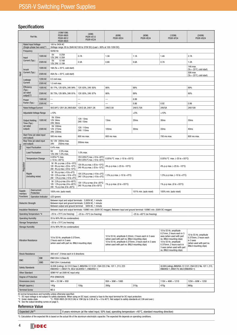
Specifications
Part No.
(10W/15W)PS5R-VB05PS5R-VB12PS5R-VB24
(30W)PS5R-VC12PS5R-VC24
(60W)PS5R-VD24
(90W)PS5R-VE24
(120W)PS5R-VF24
(240W)PS5R-VG24
Inpu
t
Rated Input Voltage(Single-phase two-wire)*1
100 to 240V AC(Voltage range: 85 to 264V AC/100 to 370V DC) (Load ≤ 80% at 100-105V DC)
Frequency 50/60 Hz
Input Current (Typ.)
100V AC 5V: 0.25A12V, 24V: 0.35A
0.7A 1.3A 1.1A 1.4A 2.7A
230V AC 5V: 0.14A12V, 24V: 0.19A
0.3A 0.8A 0.6A 0.7A 1.2A
Inrush Current (Typ.)
100V AC 18A (Ta = 25°C, cold start)14A max. (Ta = 25°C, cold start)
230V AC 45A (Ta = 25°C, cold start)30A max. (Ta = 25°C, cold start)
Leakage Current
120V AC 0.5 mA max.
230V AC 1.0 mA max.
Efficiency (Typ.)(at rated output)*2
100V AC 5V: 77%, 12V: 82%, 24V: 84% 12V: 83%, 24V: 85% 86% 88% 89%
230V AC 5V: 73%, 12V: 80%, 24V: 81% 12V: 85%, 24V: 87% 86% 89% 90%
Power Factor (Typ.)
100V AC — — — 0.99
230V AC — — — 0.86 0.92 0.96
Outp
ut
Rated Voltage/Current 5V/2.0A*3, 12V/1.3A, 24V/0.65A 12V/2.5A, 24V/1.3A 24V/2.5A 24V/3.75A 24V/5A 24V/10A
Adjustable Voltage Range ±10% ±5% ±10%
Output Holding Time (Typ.) (at rated output)
100V AC 5V: 53ms12V: 34ms 24V: 36ms
12V: 13ms24V: 15ms
13ms 20ms 30ms 30ms
230V AC 5V: 330ms 12V: 215ms 24V: 230ms
12V: 110ms 24V: 110ms
105ms 30ms 33ms 40ms
Start Time (at rated input and output)
500 ms max. 600 ms max. 800 ms max. 700 ms max. 800 ms max.
Rise Time (at rated input and output)
5V, 12V: 200ms max. 24V: 250ms max.
200ms max.
Regu
latio
n
Input Fluctuation 0.4% max.
Load Fluctuation5V: 2.5% max. 12V, 24V: 1.0% max.
1.0% max.
Temperature Change0.05%/°C max. (–10 to +65°C)
12V: 0.05%/°C max. (–10 to +50°C) 24V: 0.05%/°C max. (–10 to +55°C)
0.05%/°C max. (–10 to +55°C) 0.05%/°C max. (–25 to +55°C)
Ripple (including noise)
5V: 8% p-p max. (–25 to –10°C)12V: 6% p-p max. (–25 to –10°C)24V: 4% p-p max. (–25 to –10°C)
12V: 6% p-p max. (–25 to –10°C)24V: 4% p-p max. (–25 to –10°C)
4% p-p max. (–25 to –10°C) 4% p-p max. (–25 to –10°C)
5V: 5% p-p max. (–10 to +0°C)12V: 2.5% p-p max. (–10 to +0°C)24V: 1.5% p-p max. (–10 to +0°C)
12V: 2.5% p-p max. (–10 to +0°C)24V: 1.5% p-p max. (–10 to +0°C)
1.5% p-p max. (–10 to +0°C) 1.5% p-p max. (–10 to +0°C)
5V: 2.5% p-p max. (0 to +65°C)12V: 1.5% p-p max. (0 to +65°C)24V: 1% p-p max. (0 to +65°C)
12V: 1.5% p-p max. (0 to +50°C)24V: 1% p-p max. (0 to +55°C)
1% p-p max. (0 to +55°C) 1% p-p max. (0 to +55°C)
Supple-mentary Functions
Overcurrent Protection
105% min. (auto reset) 101% min. (auto reset) 105% min. (auto reset)
Operation Indicator LED (green)
Dielectric StrengthBetween input and output terminals: 3,000V AC, 1 minuteBetween input and ground terminals: 2,000V AC, 1 minuteBetween output and ground terminal: 500V AC, 1 minute
Insulation Resistance Between input and output terminals: 100MΩ min. (500V DC megger), Between input and ground terminal: 100MΩ min. (500V DC megger)
Operating Temperature *4 –25 to +75°C (no freezing) –25 to +70°C (no freezing) –25 to +65°C (no freezing)
Operating Humidity 20 to 90% RH (no condensation)
Storage Temperature –25 to +75°C (no freezing)
Storage Humidity 20 to 90% RH (no condensation)
Vibration Resistance10 to 55 Hz, amplitude 0.375mm, 2 hours each in 3 axes(when used with part no. BNL6 mounting clips)
10 to 55 Hz, amplitude 0.33mm, 2 hours each in 3 axes (when used with part no. BNL6 mounting clips)10 to 55 Hz, amplitude 0.375mm, 2 hours each in 3 axes (when used with part no. BNL8 mounting clips)
10 to 55 Hz, amplitude 0.21mm, 2 hours each in 3 axes (when used with part no. BNL6 mounting clips)10 to 55 Hz, amplitude 0.375mm, 2 hours each in 3 axes (when used with part no. BNL8 mounting clips)
10 to 55 Hz, amplitude 0.375mm, 2 hours each in 3 axes (when used with part no. BNL6 mounting clips)
Shock Resistance 300 m/s2, 3 times each in 6 directions
EMCEMI EN61204-3 (Class B)
EMS EN61204-3 (industrial)
Safety StandardsUL508 (Listing), UL1310 Class 2, ANSI/ISA-12.12.01, CSA C22.2 No. 107.1, 213, 223EN60950-1, EN50178, SELV (UL60950-1, EN60950-1)
UL508 (Listing), ANSI/ISA-12.12.01, CSA C22.2 No. 107.1, 213, EN60950-1, EN50178, SELV (EN60950-1)
Other Standard SEMI F47 (at 208V AC input only)
Degree of Protection IP20 (EN60529)
Dimensions (mm) 90H × 22.5W × 95D 95H × 36W × 108D 115H × 46W × 121D 125H × 60W × 125D
Weight (approx.) 140g 150g 260g 310g 470g 960g
Terminal Screw M3.5
At normal temperature and humidity unless otherwise specified.*1: DC input voltage is not subject to safety standards. When using on DC input, connect a fuse to the input terminal for DC input protection.*2: Under stable state. *3: PS5R-VB05 (5V DC/2.0A) is 10W (Up to 3.0A at Ta = 0 to 40°C. Not subject to safety standards at 2.0A and over.)*4: See the output derating curves on page 5.
Reference ValueExpected Life*5 8 years minimum (at the rated input, 50% load, operating temperature +40°C, standard mounting direction)
*5: Calculation of the expected life is based on the actual life of the aluminum electrolytic capacitor. The expected life depends on operating conditions.
5
PS5R-V Switching Power Supplies
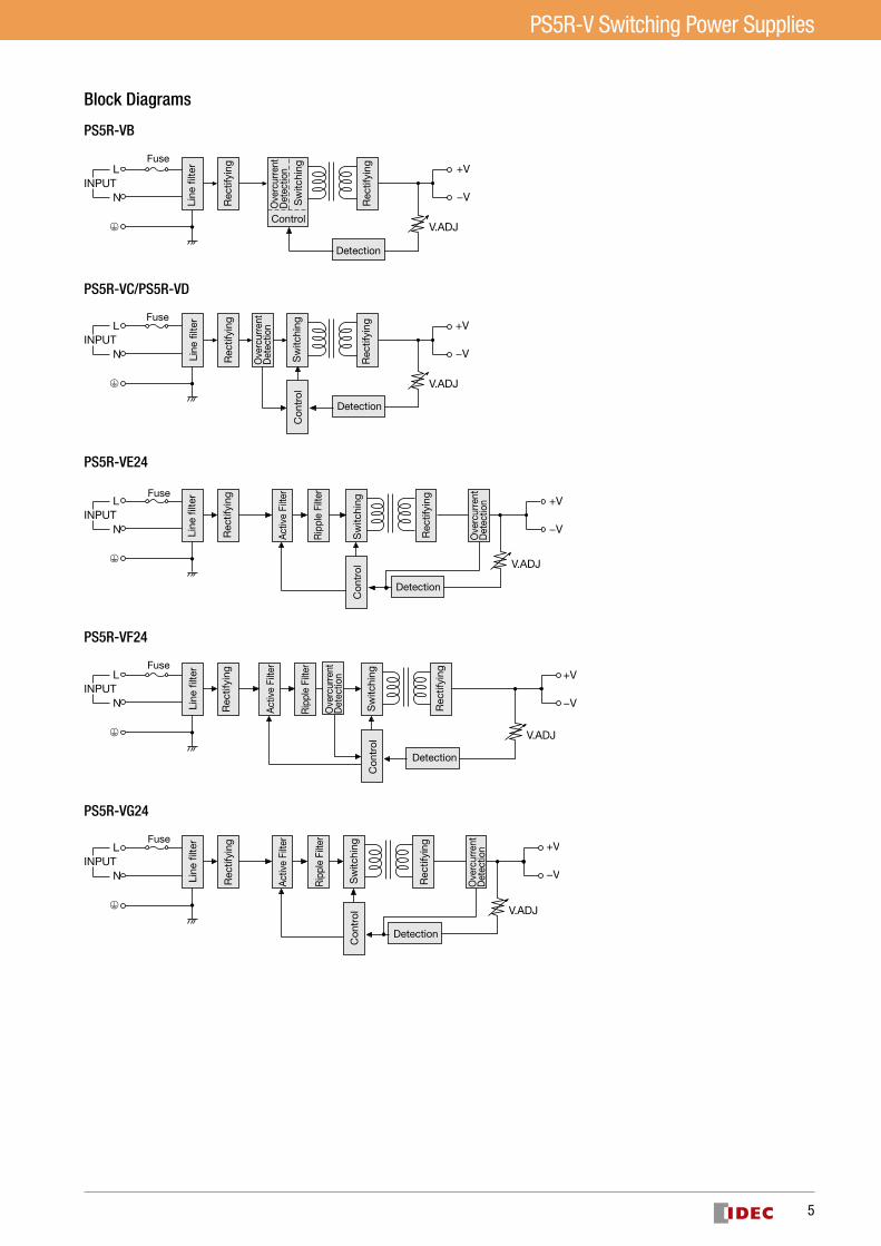
Block Diagrams
PS5R-VB
V.ADJ
L
NINPUT
+V
−VSw
itchi
ng
Control
Detection
Fuse
Rec
tifyi
ng
Rec
tifyi
ng
Line
�lte
r
Ove
rcur
rent
Det
ectio
nPS5R-VC/PS5R-VD
V.ADJ
L
NINPUT
+V
−VSw
itchi
ngC
ontr
ol
Detection
Fuse
Rec
tifyi
ng
Rec
tifyi
ng
Line
�lte
r
Ove
rcur
rent
Det
ectio
n
PS5R-VE24
L
NINPUT
V.ADJ
+V
−V
Sw
itchi
ngC
ontr
ol
Detection
Fuse
Rec
tifyi
ng
Act
ive
Filte
r
Rip
ple
Filte
r
Rec
tifyi
ng
Line
�lte
r
Ove
rcur
rent
Det
ectio
n
PS5R-VF24
L
NINPUT
V.ADJ
+V
−VSw
itchi
ngC
ontr
ol
Detection
Fuse
Rec
tifyi
ng
Rec
tifyi
ng
Act
ive
Filte
r
Rip
ple
Filte
r
Line
�lte
r
Ove
rcur
rent
Det
ectio
n
PS5R-VG24
L
NINPUT
V.ADJ
+V
−VSw
itchi
ngC
ontr
ol
Detection
Fuse
Rec
tifyi
ng
Act
ive
Filte
r
Rip
ple
Filte
r
Rec
tifyi
ng
Line
�lte
r
Ove
rcur
rent
Det
ectio
n

6
PS5R-V Switching Power Supplies
Mounting A(Vertical, standard)
Mounting B(Upright)
Mounting C(Left side up)
Mounting D(Right side up)
Mounting E(Upside down)
Mounting F(Downward)
Up
Mounting Style
Mounting A
Mounting B, C, D, E, F
Mounting E
Mounting E
Mounting E
Mounting B
-30 -20 -10 0 10 20 30 40 50 60 70 800
10
20
30
40
50
60
70
80
90
100
-30 -20 -10 0 10 20 30 40 50 60 70 800
10
20
30
40
50
60
70
80
90
100
Input Voltage: 85-100V AC
Input Voltage: 85-100V AC
Mounting F
Mounting A Mounting A, B
MountingC
Mounting B, C, D, E, F
MountingB, C, D, F
MountingB, C, F
Mounting D, E, F
Input Voltage: 85-100V AC
Input Voltage: 85-100V AC
-30 -20 -10 0 10 20 30 40 50 60 70 800
10
20
30
40
50
60
70
80
90
100
-30 -20 -10 0 10 20 30 40 50 60 70 800
10
20
30
40
50
60
70
80
90
100
Mounting B, C, D
Mounting A
Mounting A
Mounting A
Out
put
Cur
rent
(%)
Operating Temperature (˚C) Operating Temperature (˚C) Operating Temperature (˚C)
Operating Temperature (˚C)
Operating Temperature (˚C)
Operating Temperature (˚C)
Out
put
Cur
rent
(%)
Out
put
Cur
rent
(%)
Out
put
Cur
rent
(%)
Out
put
Cur
rent
(%)
Out
put
Cur
rent
(%)
Mounting F
Mounting C, E
-30 -20 -10 0 10 20 30 40 50 60 70 800
10
20
30
40
50
60
70
80
90
100
MountingB, D
Mounting A
Operating Temperature (˚C)
Out
put
Cur
rent
(%)
-30 -20 -10 0 10 20 30 40 50 60 70 800
10
20
30
40
50
60
70
80
90
100
-30 -20 -10 0 10 20 30 40 50 60 70 800
10
20
30
40
50
60
70
80
90
100
Operating Temperature Approved by Safety Standards
Part No.UL508, CSA C22.2 No.107.1, ANSI/ISA12.12.01, EN60950-1, EN50178
Mounting A
Mounting B
Mounting C
Mounting D
Mounting E
Mounting F
PS5R-VB05, -VB12, -VB24 65 60 60 60 60 60
PS5R-VC12 50 45 45 45 45 45PS5R-VC24 55 55 50 45 45 45PS5R-VD24 55 40 40 40 45 35PS5R-VE24 50 40 40 40 45 40PS5R-VF24 55 40 45 40 45 35PS5R-VG24 50 35 30 30 45 30
PS5R-VC12
PS5R-VE24PS5R-VD24
85 100 264100
(ACV)(DCV) 140 370
0
10
20
30
40
50
60
70
80
90
100
Input Voltage (V)
Out
put
Cur
rent
(%)
PS5R-VG24
Output Current vs. Input Voltage (derating curves)
PS5R-VG24
PS5R-VF24
PS5R-VC24PS5R-VB05, -VB12, -VB24
CharacteristicsOperating Temperature vs. Output Current (Derating Curves)Conditions: Natural air cooling (Operating temperature is the temperature around the switching power supply.)

7
PS5R-V Switching Power Supplies
Overcurrent Protection Characteristics
Parts Description PS5R-VB/VC
PS5R-VB/VC/VD/VF
PS5R-VD/VE/VF
PS5R-VE24
PS5R-VG
PS5R-VG24
Marking Name Description
L, N AC Input Terminal Voltage range: 85 to 264V AC/100 to 370V DC
Ground Terminal Be sure to connect this terminal to a proper ground.
+V, –V DC Output Terminals +V: Positive output terminal–V: Negative output terminal
VR.ADJ Output Voltage Adjustment Turning clockwise increases the output voltage.Turning counterclockwise decreases the output voltage.
DC ON Operation Indicator (green) Lights when the output voltage is on.
-30 0 1000
100
00
10095
00
10095
100 100
105 and over105 and over
101 and overOutput Current (%)Output Current (%)Output Current (%)
Out
put
Vol
tage
(%)
Out
put
Vol
tage
(%)
Out
put
Vol
tage
(%)
Inte
rmitt
ent
Op
erat
ion
Intermittent Operation Intermittent Operation

8
PS5R-V Switching Power Supplies
Dimensions
35.3
44.9
106.
5
60
9.5 9.5 9.5 9.5
9.5 9.5
9.3
5.5
125
4.5
125
3.8
115
988.
5
4623
11.5 11.5
4.5
44.9
35.3
3.8
121
36
95798
20
10 10108
3.8
4.5
24.9
35.3
3.8
95
4.4
35.3
27.3
61.6
12.2
8.2
90
9.522.5
5-M3.5Screw Terminal
5-M3.5Screw Terminal
5-M3.5Screw Terminal
5-M3.5Screw Terminal
PS5R-VD/VE
PS5R-VF
PS5R-VG
PS5R-VB/VC
All dimensions in mm.
Tolerance: ±1mm

9
PS5R-V Switching Power Supplies
Dimensions
Mounting hole layoutwhen installing ona panel directly
Mounting hole layoutwhen installing ona panel directly
Mounting hole layoutwhen installing ona panel directly
Mounting hole layoutwhen installing ona panel directly
Mounting hole layoutwhen installing ona panel directly
Mounting holelayout for sidemounting
Side View
Side View
Front View
Front View
Front View Side View
Front View Side View
Front View Side View
Side View Back ViewMounting Screws(4 M3×6 countersunk screws)
13.6
16.4
96.7
5.528.8
10.0
10.0
12
112
102
26
105
10.2
9.9
109.8
1224.7
112
120
102.
011
0
4462.9
2638
105
115
3648
125
135
36
125
10.2
9.9
122.8
135
145
28
3928
135
28
10.5 10.5
145
10
130.6
56
138.
6
56
148.
6
138.
6
5670
62.3 29.5
11.8
31
11.8
2-M4 or ø2-4.5 holes
2-M4 or ø2-4.5 holes
2-M4 or ø2-4.5 holes
2-M4 or ø2-4.5 holes
4-M4 or ø4-4.5 holes
4-M4 or ø4-4.5 holes
Panel Mounting BracketPS9Z-5R1B
PS9Z-5R1C
PS9Z-5R1E
PS9Z-6R1F
PS9Z-6R2F Side-mount
PS9Z-5R2B Side-mount
When installed on switching power supply
All dimensions in mm.
Tolerance: ±1mm

10
PS5R-V Switching Power Supplies
Mounting on DIN Rails1. Use a 35mm-wide DIN rail.2. Fasten the DIN rail to a mounting plate using screws.3. Place the PS5R-V on the DIN rail as shown with input terminal side up
(), and press the PS5R-V towards the DIN rail (). Make sure that the PS5R-V is installed firmly.
4. Use BNL6 mounting clips for fastening the PS5R-V on the DIN rail. Use of BNL8 mounting clips is recommended when excessive vibration or shock is anticipated. Do not use the PS5R-V when it is subject to vibra-tion constantly.
Removal•Insert a flat screwdriver into the slot in the clamp, and pull out the clamp
until it clicks (). The lock mechanism is released and the PS5R-V can be removed (). When mounting the PS5R-V again, push in the latch first.
Notes for installation•Do not close the top and bottom openings of the PS5R-V to allow for heat
radiation by convection.•Maintain a minimum of 10 mm clearance around the PS5R-V, except for
the top and bottom openings.•When mounting multiple PS5R-V switching power supplies side by side,
maintain a minimum of 10 mm clearance. Observe the derating curves in consideration of the ambient temperature.
10mm minimum
•When the derating voltage may exceed the recommended value, provide forced air-cooling.
•Make sure to wire the ground terminal correctly.•For wiring, use wires of heat resistance of 60oC or higher (PS5R-VB: 80oC
or higher). Use copper wire of the following sizes, according to the rated current.
Terminal Wire Size (allowable current) Wire Type
Input AWG18 to 14Copper Solid/StrandedOutput
AWG18 to 14 (AWG18: 7A, AWG16: 10A, AWG14: 15A)
Cross-sectional areaAWG18: 0.82mm2, AWG16: 1.31mm2, AWG14: 2.0mm2
Note: Wires of the above size must be used to comply with UL508, CSA C22.2 No. 107.1.
Applicable crimp terminal (reference)
7.0 max.
4.1 max. 5.6 min. (PS5R-VG: 6.3 min)
ø3.6 min.
•Recommended tightening torque of the input and output terminals is 1.0 to 1.3 N·m (0.8 N·m for UL).
Safety Precautions
Operating Instructions
Mount the PS5R-V in an enclosure. Do not use the PS5R-V alone as an Electric Facilities for General Use.
Use the PS5R-V for electric facilities for business use only.
•Do not use switching power supplies with electric equipment whose malfunc-tion or inadvertent operation may damage the human body or life directly.
•Make sure that the input voltage and output current do not exceed the ratings. If the input voltage and output current exceed the ratings, electric shock, fire, or malfunction may occur.
•Do not touch the terminals of the switching power supply while input voltage is applied, otherwise electric shock may occur.
•Provide the final product with protection against malfunction or damage that may be caused by malfunction of the switching power supply.
•Operating temperatures should not exceed the ratings. Be sure to note the derating characteristics. If the operating temperature exceeds the ratings, electric shock, fire, or malfunction may occur.
•Blown fuses indicate that the internal circuits are damaged. Contact IDEC for repair. Do not just replace the fuse and reoperate, otherwise electric shock, fire, or malfunction may occur.
•Do not use the switching power supplies to charge rechargeable batteries.•Do not overload or short-circuit the switching power supply for a long period of
time, otherwise the internal elements may be damaged.•Do not disassemble, repair, or modify the power supplies, otherwise the high
voltage internal part may cause electric shock, fire, or malfunction.•The fuse inside the PS5R-V switching power supply is for AC input. Use a DC
fuse for DC input.
Mounting Removal
Clamp
11
PS5R-V Switching Power Supplies
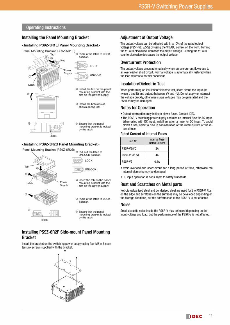
Installing the Panel Mounting Bracket
�
�
�
�
�
�
Latch
Latch
LOCK
LOCK
Panel Mounting Bracket (PS9Z-5R1�)
Panel Mounting Bracket (PS9Z-5R2B)
PowerSupply
PowerSupply
Tab
Tab
Slot
�
�
<Installing PS9Z-5R1� Panel Mounting Bracket>
<Installing PS9Z-5R2B Panel Mounting Bracket>
LOCK
UNLOCK
LOCK
UNLOCK
� Push in the latch to LOCKposition.
� Install the tab on the panel mounting bracket into the slot on the power supply.
� Install the brackets as shown on the left.
� Ensure that the panel mounting bracket is locked by the latch.
� Pull out the latch toUNLOCK position.
� Insert the tab on the panel mounting bracket into the slot on the power supply.
� Push in the latch to LOCK position.
� Ensure that the panel mounting bracket is locked by the latch.
Installing PS9Z-6R2F Side-mount Panel Mounting BracketInstall the bracket on the switching power supply using four M3 × 6 coun-tersunk screws supplied with the bracket.
Adjustment of Output VoltageThe output voltage can be adjusted within ±10% of the rated output voltage (PS5R-VE: ±5%) by using the VR.ADJ control on the front. Turning the VR.ADJ clockwise increases the output voltage. Turning the VR.ADJ counterclockwise decreases the output voltage.
Overcurrent ProtectionThe output voltage drops automatically when an overcurrent flows due to an overload or short circuit. Normal voltage is auto matically restored when the load returns to normal conditions.
Insulation/Dielectric TestWhen performing an insulation/dielectric test, short-circuit the input (be-tween L and N) and output (between +V and –V). Do not apply or interrupt the voltage quickly, otherwise surge volt ages may be generated and the PS5R-V may be damaged.
Notes for Operation•Output interruption may indicate blown fuses. Contact IDEC.•The PS5R-V switching power supply contains an internal fuse for AC input.
When using with DC input, install an exter nal fuse for DC input. To avoid blown fuses, select a fuse in consideration of the rated current of the in-ternal fuse.
Rated Current of Internal Fuses
Part No. Internal Fuse Rated Current
PS5R-VB/VC 2A
PS5R-VD/VE/VF 4A
PS5R-VG 6.3A
•Avoid overload and short-circuit for a long period of time, oth erwise the internal elements may be damaged.
•DC input operation is not subject to safety standards.
Rust and Scratches on Metal partsHot-dip galvanized steel and bonderized steel are used for the PS5R-V. Rust on the edge and scratches on the surfaces may be developed depending on the storage condition, but the performance of the PS5R-V is not affected.
NoiseSmall acoustic noise inside the PS5R-V may be heard depending on the input voltage and load, but the performance of the PS5R-V is not affected.
Operating Instructions

12
PS5R-V Switching Power Supplies
Series OperationThe following series operation is allowed. In (b) series operation, connect Schottky barrier diodes. Choose (a) series operation when using the PS5R-V as positive and negative output power supply. Insert a Shottky barrier diode for loads such as operational amplifier where outputs of two power supplies may be connected in series (Load 3). Select a Schottky diode in consider-ation of the rated current.
L
N
L
N
+V
–V
L
N
+V
–V
Load
(a)
L
N
L
N
+V
–V
L
N
+V
–V
Load 3
(b)
Load 1
Load 2
Parallel OperationParallel operation is not possible to increase the output capacity, because the internal elements and load may be damaged.
Backup OperationBackup operation is a connection method of two switching power supplies in parallel for emergency. Normally one switching power supply has a sufficient output. If one switching power supply fails, another one operates to continue the output. Make sure that the sum of power consumption by load and diode is not greater than the rated wattage (rated voltage × rated current) of one switching power supply.
+
−INAC OUT
+
−IN OUT
Load
D
D
Select a diode in consideration of: Diode's current must be more than double the PS5R-V's output current. Take heat dissipation into consideration.
Operating Instructions
Warranty
WarrantyIDEC warrantees the PS5R-V switching power supplies for a period of five years from the date of shipment.
ScopeIDEC agrees to repair or replace the PS5R-V switching power supply if the product has been operated under the following conditions. The maximum value of output capacity is within the range shown in “Operating Tempera-ture vs. Output Current" on page 5.
1. Average operating temperature (ambient temperature of switching power supply) is 40°C maximum.
2. The load is 80% maximum.3. Input voltage is the rated input voltage.4. Standard mounting style
IDEC shall not be liable for other damages including consequential, contingent or incidental damages. Warranty does not apply if the PS5R-V switching power supply was subject to:
1. Inappropriate handling, or operation beyond the specifications.2. Modification or repair by other than IDEC.3. Failure caused by other than the PS5R-V switching power supply.4. Failure caused by natural disasters.
www.idec.comUSA IDEC Corporation Tel: +1-408-747-0550 [email protected] IDEC Elektrotechnik GmbH Tel: +49-40-25 30 54 - 0 [email protected] IDEC Izumi Asia Pte. Ltd. Tel: +65-6746-1155 [email protected] IDEC Asia (Thailand) Co., Ltd Tel: +66-2-392-9765 [email protected] IDEC Australia Pty. Ltd. Tel: +61-3-8523-5900 [email protected] IDEC Taiwan Corporation Tel: +886-2-2698-3929 [email protected]
Hong Kong IDEC Izumi (H.K.) Co., Ltd. Tel: +852-2803-8989 [email protected]/Shanghai IDEC (Shanghai) Corporation Tel: +86-21-6135-1515 [email protected]/Shenzhen IDEC (Shenzhen) Corporation Tel: +86-755-8356-2977 [email protected]/Beijing IDEC (Beijing) Corporation Tel: +86-10-6581-6131 [email protected] IDEC Corporation Tel: +81-6-6398-2527 [email protected]
Speci�cations and other descriptions in this brochure are subject to change without notice.2017 IDEC Corporation, All Rights Reserved.
EP1591-6 AUGUST 2017
Head Office6-64, Nishi-Miyahara-2-Chome, Yodogawa-ku, Osaka 532-0004, Japan
Top Related