


Languages
Pages
Legal


Multi‐Se
W
PRS 9nsor Displ
Wireless Se
90 ay for PAT
ensors
T B5
Operrator’s Manuaal

SkyAzúl, Equipment Solutions www.skyazul.com 301-371-6126
NOTICE SkyAzúl makes no warranty of any kind with regard to this material, including, but not limited to, the implied warranties of merchantability and/or its fitness for a particular purpose. SkyAzúl will not be liable for errors contained in this manual or for incidental or consequential damages in connection with the furnishing, performance, or use of this manual. This document contains proprietary information, which is protected by copyright, and all rights are reserved. No part of this document may be photocopied, reproduced, or translated to another language without the prior written consent of SkyAzúl. SkyAzúl reserves proprietary rights to all drawings, photos and the data contained therein. The drawings, photos and data are confidential and cannot be used or reproduced without the written consent of SkyAzúl. The drawings and/or photos are subject to technical modification without prior notice. All information in this document is subject to change without notice.
SkyAzúl, Inc. 200 W. Main Street, Suite, 2A Middletown, MD 21769 Fax 301-371-0029 [email protected]

TABLE OF CONTENTS
1 Safety Instructions ........................................................................................... 7
1.1 EC Conformity Declaration ........................................................................ 8
2 Product Description ......................................................................................... 8
2.1 General ...................................................................................................... 8 2.2 Product Features .....................................................................................10 2.3 Base Console Kit .....................................................................................10 2.4 Product Identification ...............................................................................11 2.5 Overview of Functional Elements ............................................................12 2.6 Functional Elements ................................................................................13
3 System Startup ...............................................................................................14
3.1 Switching Device On and Off ...................................................................14 3.2 Live Video (optional) ................................................................................16 3.3 Configuring the System ...........................................................................16
3.3.1 Setting Rope Reeving ..........................................................................17
3.4 Limit Value Monitoring .............................................................................18
3.4.1 Programming LIM for Wind Sensor .....................................................20 3.4.2 Programming LIM for Load Sensor......................................................21 3.4.3 Programming LIM for Angle Sensor ....................................................22
4 System Settings (User) ..................................................................................24
4.1.1 LCD Brightness ....................................................................................25 4.1.2 Key Brightness .....................................................................................26 4.1.3 Digital Outputs .....................................................................................27 4.1.4 Set Units ..............................................................................................29
5 Installation .......................................................................................................30
5.1 Mounting the Components.......................................................................30
5.1.1 vSCALE D2 Console ...........................................................................30 5.1.2 TRS 10-W2 ..........................................................................................31 5.1.3 Magnetic Base Antenna .......................................................................33
5.2 Electrical Connection ...............................................................................34
5.2.1 Wiring of Console Connector ...............................................................34 5.2.2 Wiring of vSCALE D2 Power Harness .................................................35 5.2.3 Wiring of TRS 10-W2 ...........................................................................35 5.2.4 Wiring of TRS 10-W2 Power Harness .................................................36
SkyAzúl, Equipment Solutions www.skyazul.com
301-371-6126

6 Commissioning ...............................................................................................37
6.1 Registering Wireless Sensors..................................................................38
6.1.1 Registering a Wind Sensor ..................................................................41 6.1.2 Registering a Load Sensor ..................................................................42 6.1.3 Registering a A2B Sensor ...................................................................43 6.1.4 Registering an Angle Sensor ...............................................................44
6.2 Deleting (Removing) Sensors ..................................................................45
7 Configuring the System .................................................................................46
7.1 Sensor Calibration ...................................................................................47
7.1.1 Calibrating Load Sensor ......................................................................48 7.1.2 Calibrating Angle Sensor .....................................................................49
7.2 Limit Output Signal Setup ........................................................................50
7.2.1 Enabling Limit Output Signals for Angle Sensors ................................50 7.2.2 Enabling Limit Output Signals for Load Sensors .................................51
8 System Settings (Set-Up) ..............................................................................52
8.1.1 Alarm Volume ......................................................................................53 8.1.2 Sensor Information Transfer ................................................................54 8.1.3 Lock/Unlock System ............................................................................55
9 Service and Maintenance ..............................................................................56
9.1 Uploading Software .................................................................................57
10 Appendix .........................................................................................................58
10.1 Technical Data .........................................................................................58
10.1.1 vSCALE D2 ......................................................................................58 10.1.2 TRS 10-W2 ......................................................................................58
10.1 Wiring Diagrams ......................................................................................60
10.1.1 System Layout .................................................................................60 10.1.2 Wiring of vSCALE D2 Power Harness .............................................62 10.1.3 Wiring of TRS 10-W2 Power Harness .............................................64
SkyAzúl, Equipment Solutions www.skyazul.com
301-371-6126

Introduction
Marking of Notices
Dangers and other important notices are marked as follows in this user manual:
WARNING
Warning of direct threat of personal injury and damage to property.
Instructions on precautions to avert the danger.
CAUTION
Warning of dangerous situations. Also warns of damage to property.
Instructions for averting the danger.
IMPORTANT
Warning of possibly damaging situation for the product.
Instructions for avoiding the possibly damaging situation.
NOTE
Usage instructions and information, but no dangerous situation.
HINT
Supplementary comments and recommendations for the user.
SkyAzúl, Equipment Solutions www.skyazul.com
301-371-6126

Safety Instructions
1 Safety Instructions
In order to avoid possible person injuries and damage to property when using this device, it is essential to observe the following safety instructions.
CAUTION
The PRS 90 is an aid for displaying measured values, which are measured by various wireless
sensors and transmitted wirelessly to the central device.
Although functions are integrated in the system for monitoring adjustable limit values with visu-
al and acoustic warnings as well as a digital output when limit values are exceeded, the system
may not be used as a safety device in the sense of EN 954 or EN 13849.
The relay output may not be used as an operation limit switch for the monitoring of limits val-
ues.
The system cannot and also should not be a replacement for the good judgment or experience
of the operator or the use of safe working methods when using loading machines or other tech-
nical equipment.
The operator is responsible for the safe operation of the loading machine or other technical
equipment. He must ensure that he understands and observes the information and instructions
in their entirety.
CAUTION
The device is used together with wireless load sensors in lifting equipment with a multiple
reeved lifting rope, then it is of fundamental importance for a correct load display and for the
limit value monitoring to correctly input the number of rope reevings according to the actual
number of rope reevings.
Therefore, the necessary inputs may only be made by operators who are familiar with the opera-
tion of the system.
IMPORTANT
Connection to the wrong power supply will cause damage to the device.
The device may only be connected to a DC voltage source of 10 V to 30 V!
SkyAzúl, Equipment Solutions www.skyazul.com Page 7
301-371-6126

1.1 EC Conformity Declaration
The technical design and construction of the vSCALE D2 console corresponds to requirements of the EMC directive 2004/108/EC and therefore carries the CE symbol.
The device complies with the following harmonized standards: EN 12895:200, EN 13309:2010, EN ISO 14982: 2009
The full conformity declaration is available from the manufacturer on request.
2 Product Description
2.1 General
The PRS 90 is an aid for displaying measured values, which are measured by various wireless sensors and transmitted wirelessly to the central device.
Although functions are integrated in the system for monitoring adjustable limit values with visual and acoustic warnings as well as a relay output when limit values are exceeded, the system may not be used as a safety device in the sense of EN 954 or EN 13849.
The vSCALE D2 console is the operable component and display of the PRS 90, referred to below as the indicator system. The vSCALE D2 is the control for the wireless sensors from the xSENS-W1 fami-ly. The sensors are connected by a radio link in the 2.4 GHz ISM band and may be operated license-free worldwide. In order to be able to use the device, at least one wireless sensor is necessary.
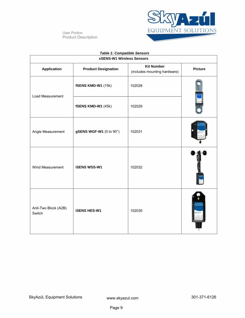
From the extensive range of Hirschmann wireless sensors, all sensors from the xSENS-W1 family can be used, see Table 1: Compatible Sensors.
A total of up to 8 sensors can be connected wirelessly.
Which Sensors Can Be Used?
How Many Sensors Can Be Connected?
SkyAzúl, Equipment Solutions www.skyazul.com Page 8
301-371-6126
User Portion Product Description
Table 1: Compatible Sensors
xSENS-W1 Wireless Sensors
Application Product Designation Kit Number
(includes mounting hardware) Picture
Load Measurement
fSENS KMD-W1 (15k) 102028
fSENS KMD-W1 (45k) 102029
Angle Measurement gSENS WGF-W1 (0 to 90°) 102031
Wind Measurement iSENS WSS-W1 102032
Anti-Two Block (A2B) Switch
iSENS HES-W1 102030
SkyAzúl, Equipment Solutions www.skyazul.com Page 9
301-371-6126

User Portion Product Description
2.2 Product Features
Features:
Easily and clearly shows operator required information
Wireless operation
Can display in multiple units (Domestic (lbs.), Domestic (kips), and Metric (SI))
Load display: Display of current load & reeving
Angle display: Display of current boom angle
Wind display: Display of current wind speed
A2B display: Display of monitoring OK or two-blocked
Multiple limits can be set
Acoustic alarm on reaching a set limit value
Monitoring and display of connection status of connected sensors
Digital Output for exceeding set limit values and for two-blocked A2B switches
Protection class IP 66/67
Operating temperature range of -40°C to +75°C (-40°C to +85°C storage)
Voltage supply 10 to 30 V DC
2.3 Base Console Kit
The console kit (HUS PN 102050) includes:
vSCALE D2 operating console
TRS 10-W2 2.4GHz wireless receiver
vSCALE D2 power harness
TRS 10-W2 power harness
vSCALE D2 mounting equipment
Magnetic base antenna with 4m connecting cable
Sensors required for PRS 90 operation purchased separately (see Table 1: Compatible Sensors).
SkyAzúl, Equipment Solutions www.skyazul.com Page 10
301-371-6126

User Portion Product Description
2.4 Product Identification
The type plate carries the unique identification of the operating console with PRS90 software installed. It is located on the left side of the console, and should have the P/N: 061093.
Please ensure you make a note of all the information on your type plate for queries about this product.
Figure 1: Type Plate Example
Type Plate Example
SkyAzúl, Equipment Solutions www.skyazul.com Page 11
301-371-6126

User Portion Product Description
2.5 Overview of Functional Elements
Figure 2: Functional Elements of vSCALE D2 Console
1 Ambient light sensor / Status LEDs
2 TFT color display 4.3 inch
3 Function keys F1 – F8
4 Rotary control (encoder) with pushbutton function
5 Set key for silencing alarms and confirming system settings
6 Home key for return to main menu
7 Esc key for return to previous menus or previous setup-ups
8 USB 2.0 interface (only for service purposes)
Legend
SkyAzúl, Equipment Solutions www.skyazul.com Page 12
301-371-6126

User Portion Product Description
2.6 Functional Elements
Function Keys F1 to F8 Calls Functions
Light Sensor: Not Used
Operating Display: Green While Supply Voltage is Connected
USB Data Display: Yellow During Data Exchange via Front USB Port
Multi-Function Light: Not Used
Wireless Indicator: Not Used
Encoder With Pushbutton Function: For Selection and Confirmation When Making Inputs
SET key: Selects Settings / Silences Alarm
HOME key: Returns to Main Working Screen
ESCAPE key: Returns to Previous Menu / Aborts Function
SkyAzúl, Equipment Solutions www.skyazul.com Page 13
301-371-6126

User Portion System Startup
User Portion 3 System Startup
At least one wireless sensor must be available in order to commission and operate the system. A guide to commissioning the PRS 90 and the wireless sensors can be found in Section 6.
3.1 Switching Device On and Off
The PRS 90 is switched on or off by connecting or disconnecting the power supply.
After switching on, the acoustic alarm sounds briefly and the system begins with a self-diagnosis rou-tine.
After boot-up, the Main Working Screen appears on the display. The main working screen has 3 screens. The first screen displays sensors 1-4 and is automatically displayed upon startup. Turn the rotary knob counter-clockwise to scroll down to pages 2 and 3.
The sensor bar will display the active sensors in all screens (excluding the camera screen).
Figure 3: Main Working Screen (1 of 3)
Sensor 1
Sensor 3
Sensor 2
Sensor 4
Sensor 1 Sensor 2 Sensor 3 Sensor 4
Sensor 5 Sensor 6 Sensor 7 Sensor 8
Sensor Bar
SkyAzúl, Equipment Solutions www.skyazul.com Page 14
301-371-6126

User Portion System Startup
Figure 4: Main Working Screen (2 of 3)
Figure 5: Main Working Screen (3 of 3)
Sensor 3
Sensor 5
Sensor 4
Sensor 6
Sensor 5
Sensor 7
Sensor 6
Sensor 8
SkyAzúl, Equipment Solutions www.skyazul.com Page 15
301-371-6126
User Portion System Startup
3.2 Live Video (optional)
You can (optionally) show the live video image on the display. Pressing F4 from the Main Working Screen will call up the Live Video.
3.3 Configuring the System
If the system is used together with wireless load sensors, the rope reeving must be set (see Section 3.3.1). The sensor must also be calibrated (see Section 7.1.1).
CAUTION
The device is used together with wireless load sensors in lifting equipment with a multiple
reeved lifting rope, then it is of fundamental importance for a correct load display and for the
limit value monitoring to correctly input the number of rope reevings according to the actual
number of rope reevings.
Therefore, the necessary inputs may only be made by operators who are familiar with the opera-
tion of the system.
If the system is used together with wireless angle sensors, the zero point of the angle sensor must be adjusted after mounting (see Section 7.1.2).
SkyAzúl, Equipment Solutions www.skyazul.com Page 16
301-371-6126

User Portion System Startup
3.3.1 Setting Rope Reeving
Setting the rope reeving is only necessary and possible when using active load sensors. The rope reev-ing can be set by pressing F8 on the Main Working screen. This will call up the Load Reeving screen.
Figure 6: Load Reeving Screen (example)
Press the corresponding function button to increase the reeving by 1 (until 25, when it then cycles to 1). When the reeving is changed, the corresponding sensor icon button in the sensor bar will show the number of reevings.
Rope Reeving Screen Example
SkyAzúl, Equipment Solutions www.skyazul.com Page 17
301-371-6126

User Portion System Startup
3.4 Limit Value Monitoring
The system features a ‘limit value monitoring’ function with programmable limit values. The functions can be set individually or in combination. Press F5 from the Add/Delete/Calibrate/LIM Screen to call up the Limit screen.
Figure 7: LIM Screen (example)
Program Limit for Wind Sensor (see Section 3.4.1)
Program Limit for Load Sensor (see Section 3.4.2)
Program Limit for Angle Sensor (see Section 3.4.3)
Limits for A2B are not able to be set. If limit values are set, they will be stored after the system is switched off. The limits will need reactivated if the system goes through a power cycle.
NOTE
Limit Output Signals can be enabled for load and angle sensors. See Section 7.2.
Relays will need to be added for Limit Output Signals! DOs 1-3 supply ground.
LIM Screen Example
What Limits Can Be Set?
Saving Values
SkyAzúl, Equipment Solutions www.skyazul.com Page 18
301-371-6126

User Portion System Startup
Active limit values are indicated by the display of color-highlighted symbols. The icons in the sensor bar and the sensor values on the main screen will change color.
Icons Color Description
Blue Limits Not Activated
Green Limit Activated and Within Set Limit A2B OK
Yellow Limit Nearing Set Limit
Red
Limit Exceeded
A2B Not OK
Audible alarm will sound
If Limit Output Signal Functionality is enabled
(always enabled for A2B), the Digital Output will
go low (see Section 4.1.3 for more detail)
Figure 8: Main Working Screen with Activated Limits (example)
Warnings and Alarms
Not Activated
A2B OK
Limit Exceeded
Limit Nearing Set Value
SkyAzúl, Equipment Solutions www.skyazul.com Page 19
301-371-6126

User Portion System Startup
3.4.1 Programming LIM for Wind Sensor
Press the corresponding function button from the LIM screen to set the limit. This will call up the Wind Sensor Limit Screen
Figure 9: Set Wind Sensor Limit Screen
Wind Sensor Limits are set by the following instructions:
Turn the rotary knob to change the highlighted digit to the desired number.
o Limit value will increment/decrement by 1 unit
Press F3 to set & activate / deactivate limit
o Wind Sensor icon in sensor bar will change color
o Set Limit Button (F3) will change color
Instructions
Limit Value
Current Value
SkyAzúl, Equipment Solutions www.skyazul.com Page 20
301-371-6126

User Portion System Startup
3.4.2 Programming LIM for Load Sensor
Press the corresponding function button from the LIM screen to set the limit. . This will call up the Load Sensor Limit Screen.
Figure 10: Set Load Sensor Limit Screen
Load Sensor Limits are set by the following instructions:
Turn the rotary knob to change the highlighted digit to the desired number
o Limit Value will increment/decrement by 50 units x reeving multiplier
Example: If load sensor has a reeving of 2, the limit value will increment by 100 (50*2=100)
Press F3 to set & activate / deactivate limit
o Load Sensor icon in sensor bar will change color
o Set Limit Button (F3) will change color
Instructions
Limit Value
Current Value Enable/Disable
Limit Output Signal See Section 7.2.2
SkyAzúl, Equipment Solutions www.skyazul.com Page 21
301-371-6126

User Portion System Startup
3.4.3 Programming LIM for Angle Sensor
Press the corresponding function button from the LIM screen to set the limit. . This will call up the Angle Sensor Limit Screen.
Figure 11: Set Angle Sensor Limit Screen
The upper angle limits for Angle Sensors are set by the following instructions:
Boom up to desired maximum angle value (current value is displayed at top of screen)
Press the Set Upper Limit Button (F2) to set the upper value as the current angle value (this will change the upper limit value)
Press F3 to activate/deactivate upper limit
o Upper Limit I / O Button (F3) will change color
Instructions Upper Limit
Upper Angle Limit Value
Current Value
Lower Angle Limit Value
Enable/Disable Limit Output Signal See Section 7.2.1
SkyAzúl, Equipment Solutions www.skyazul.com Page 22
301-371-6126

User Portion System Startup
The lower angle limits for Angle Sensors are set by the following instructions:
Boom up to desired maximum angle value (current value is displayed at top of screen)
Press the Set Upper Limit Button (F2) to set the upper value as the current angle value (this will change the upper limit value)
Press F3 to activate/deactivate upper limit
o Upper Limit I / O Button (F3) will change color
Instructions Lower Limit
SkyAzúl, Equipment Solutions www.skyazul.com Page 23
301-371-6126

User Portion System Settings (User)
4 System Settings (User)
The Setup menu allows the user to configure various settings and view Digital Output statuses. Press-ing F8 from the Sensor Add/Delete/Calibrate/LIM Screen will call up the Sensor Calibration screen.
Figure 12: Setup Screen
LCD Brightness (see Section 4.1.1)
Sensor Information Transfer (see Section 8.1.2)
Key Brightness (see Section 4.1.2)
Set Units (see Section 4.1.4)
Alarm Volume (see Section 8.1.1)
Lock/Unlock System (see Section 8.1.3)
Digital Outputs (see Section 4.1.3)
NOTE
The symbol indicates that the screen is password protected. If the system is not unlocked, pressing password protect function buttons will have no function.
See Section 8.1.3 for more information on unlocking the system.
Function Keys
Software Version
SkyAzúl, Equipment Solutions www.skyazul.com Page 24
301-371-6126

User Portion System Settings (User)
4.1.1 LCD Brightness
The brightness of the LCD screen is able to be adjusted from 5% to 100%. Pressing F1 from the Setup Screen will call up the LCD Brightness Screen.
Figure 13: LCD Brightness Screen
LCD Brightness is set by the following instructions:
Turn the rotary knob to change the LCD Brightness between 5% and 100%
Once the desired brightness is selected, press the SET key to set.
To abort, press the ESCAPE key
Instructions
SkyAzúl, Equipment Solutions www.skyazul.com Page 25
301-371-6126

User Portion System Settings (User)
4.1.2 Key Brightness
The brightness of the function keys is able to be adjusted from 5% to 100%. Pressing F2 from the Setup Screen will call up the Key Brightness Screen.
Figure 14: Key Brightness Screen
LCD Brightness is set by the following instructions:
Turn the rotary knob to change the LCD Brightness between 5% and 100%
Once the desired brightness is selected, press the SET key to set.
To abort, press the ESCAPE key
Instructions
SkyAzúl, Equipment Solutions www.skyazul.com Page 26
301-371-6126

User Portion System Settings (User)
4.1.3 Digital Outputs
The system has three digital outputs. Pressing F4 from the Setup Screen will call up the Digital Output Screen.
Figure 15: Digital Output Screen
Limit output signals can be enabled when user set limits are exceeded for angle or load sensors. Limit output signal functionality cannot be disabled for A2B sensors. This function can be set for individual sensors or in combination. See Section 7.2 for enabling limit output signals Section 3.4 for setting user limits.
In order for a digital output to change state, the limit output signal must be activated and limits must be set. When both of these conditions are met, an audible alarm will sound, the corresponding digital out-put will go low, and the digital output display will turn red.
Digital Output High (default) Low (activated)
1
Default A2B OK Load limit output signal acti-
vated and under set limit
ATB Error Load limit output signal activated
and exceeded limit
2 Default Angle lower limit activated and
above set limit
Angle lower limit activated and exceeded limit
3 Default Angle upper limit activated and
below set limit
Angle upper limit activated and exceeded limit
Description of DOs
SkyAzúl, Equipment Solutions www.skyazul.com Page 27
301-371-6126

User Portion System Settings (User)
Figure 16: Digital Output Screen with DO1 Low
NOTE
Relays will need to be added for Limit Output Signals! DOs 1-3 supply ground.
Example
SkyAzúl, Equipment Solutions www.skyazul.com Page 28
301-371-6126

User Portion System Settings (User)
4.1.4 Set Units
The units can be set in the Setup Screen by pressing F6. Every time F6 is pressed, the units will change. This is indicated visually by the button changing.
SI
US (lbs.)
US
(kips)
Description Unit Buttons
SkyAzúl, Equipment Solutions www.skyazul.com Page 29
301-371-6126

Set-Up Portion Installation
Set-Up Portion 5 Installation
5.1 Mounting the Components
The equipment is supplied complete with necessary mounting parts. For mounting the wireless sen-sors, please refer to the instructions provided with the respective sensor.
NOTE
PLEASE RECORD SENSOR ID INFORMATION PRIOR TO INSTALLING YOUR SENSORS
See Section 6.1 for more detail.
5.1.1 vSCALE D2 Console
The vSCALE D2 Console is mounted using a ram mount and ram mount adapter (see Figure 17: Mounting the Console for visual detail). The recommended mounting method is as follows:
1. Attach the Ram Mount Adapter to the back of the console
2. Plug the vSCALE D2 power harness into the console
3. Attach one end the Ram Mount to the back of the console
4. Attach the opposite end of the Ram Mount to the cab
SkyAzúl, Equipment Solutions www.skyazul.com Page 30
301-371-6126

Set-Up Portion Installation
Figure 17: Mounting the Console
5.1.2 TRS 10-W2
The TRS 10-W2 must be mounted in a suitable place on a sufficiently firm surface with the connectors at the bottom. The device may be used both indoors and outdoors, but must be mounted such that the LEDs are visible. For more information on the TRS10-W2, please refer to the TRS10-W2 manual.
Figure 18: TRS 10-W2
Ram Mount Adapter Part Number: 608460
Ram Mount (Partially Shown
Part Number: 031-300-060-382)
Antenna Socket
Central Plug
Sensor LEDs
Power LED
CAN LED
SkyAzúl, Equipment Solutions www.skyazul.com Page 31
301-371-6126

Set-Up Portion Installation
The distance between the holes in the housing is 102mm.
Figure 19: Dimensions of TRS10-W2
SkyAzúl, Equipment Solutions www.skyazul.com Page 32
301-371-6126

Set-Up Portion Installation
5.1.3 Magnetic Base Antenna
The antenna radiator must first be screwed hand tight onto the thread on the top side of the antenna space until a soft stop is felt.
The antenna has a magnetic baseplate and adheres securely to all ferromagnetic surfaces.
Lay the antenna cable in such a way that it is neither squeezed nor laid upon sharp edges. Doing so can cause the cable to be damaged
Figure 20: Magnetic Base Antenna
NOTE
Optimal ranges are achieved if the antenna is in horizontal alignment with the wireless sensor
antennas.
After laying the antenna cable, connect the coaxial connector of the antenna to the antenna socket on the underside of the TRS 10-W2. Screw the connector on hand tight.
Figure 21: Connecting Antenna to TRS10-W2
IMPORTANT
The function of the antenna (and thus the whole system) can be impaired if a mismatching an-
tenna radiator is used.
Always use the antenna radiator contained in the console kit (HUS PN 102050).
Magnetic baseplate
Antenna radiator 2.4 GHz
Antenna base
SkyAzúl, Equipment Solutions www.skyazul.com Page 33
301-371-6126

Set-Up Portion Installation
5.2 Electrical Connection
Connection to power is done through the vSCALE D2 power harness. The open end of the cable is to be connected properly using wire and ferrules.
5.2.1 Wiring of Console Connector
Please refer to the following illustration for the pin configuration of the console, located on the back of the vSCALE D2.
Figure 22: vSCALE D2 Pinout
Pin Description Pin Description
1 Vcc +9…36 V DC 14 USB D-
2 Ignition 15 USB D+
3 GND 16 RS232 RxD
4 Car GND 17 RS232 TxD
5 n.c 18 RS232 GND
6 n.c. 19 AI/DI 3
7 n.c. 20 AI/DI 1
8 CAN 1 High 21 AI/DI 2
9 CAN 1 Low 22 AI/DI 4
10 CAN 2 High 23 SERV_ENABLE
11 CAN 2 Low 24 DO3
12 USB Vcc (+5V) 25 DO 1
13 USB GND 26 DO2
Connector View
Pin Assignment
SkyAzúl, Equipment Solutions www.skyazul.com Page 34
301-371-6126

Set-Up Portion Installation
5.2.2 Wiring of vSCALE D2 Power Harness
Please refer to Section 10.1.2.
5.2.3 Wiring of TRS 10-W2
Please refer to the following illustration for the pin configuration of the wireless receiver, located on the bottom of the TRS10-W2.
Figure 23: TRS10-W2 Pinout
Pin Description Pin Description
1 V DC (10-30V) 7 n.c.
2 GND 8 n.c.
3 KGND (ground) 9 n.c.
4 n.c. 10 n.c.
5 KGND (shield) 11 CAN 1 High
6 n.c. 12 CAN 1 Low
Connector View
Pin Assignment
SkyAzúl, Equipment Solutions www.skyazul.com Page 35
301-371-6126

Set-Up Portion Installation
5.2.4 Wiring of TRS 10-W2 Power Harness
Refer to Section 10.1.3.
5.2.5 Connecting the TRS 10-W2 Power Harness
Insert the central plug of the cable until it clicks, and then push the boot completely over the connector:
Figure 24: Connecting TRS10-W2 Power Harness
To comply with the EMC requirements for the surge voltages of power supply lines (EN 61000-4-5), it is necessary that the ground wire is conductively connected to the vehicle chassis when mounting the iFLEX TRS10-W2. Refer to the TRS10-W2 manual for more detail.
Figure 25: Connecting TRS10-W2 Power Harness for EMC Compliance
SkyAzúl, Equipment Solutions www.skyazul.com Page 36
301-371-6126

Set-Up Portion Commissioning
6 Commissioning
At least one wireless sensor must be available in order to commission and operate the system. You will find a guide to commissioning the PRS 90 and the wireless sensors below.
After boot-up, the Main Working Screen appears on the display:
Figure 26: Main Working Screen (no sensors installed)
The main working screen has 3 screens. The first screen displays sensors 1-4 and is automatically displayed upon startup. Turn the rotary knob counter-clockwise to scroll down to pages 2 and 3.
The sensor bar will display the active sensors in all screens (excluding the camera screen). See Sec-tion 3.1 for examples of the Main Working Screen with sensors installed.
Sensor Bar
SkyAzúl, Equipment Solutions www.skyazul.com Page 37
301-371-6126

Set-Up Portion Commissioning
6.1 Registering Wireless Sensors
Every wireless sensor to be used must be registered once on the central device. Wireless sensors that are no longer to be used must be deleted from the list of installed sensors (see Section 6.2).
NOTE
THE FOLLOWING INFORMATION WILL BE NEEDED TO REGISTER SENSORS PRIOR TO
INSTALLATION.
PLEASE COMPLETE THIS STEP BEFORE INSTALLING YOUR SENSORS
Before registering any sensor, the following must be done:
Open the battery compartment
Remove the batteries
Make note of the Node ID
o The Node ID is a 5 digit number
o The Node ID is located above the software version number (see Figure 27: Node ID)
Install batteries
Close and secure the battery compartment
Use Sections 6.1.1, 6.1.2, 6.1.3, and 6.1.4 to register sensors
Figure 27: Node ID
SkyAzúl, Equipment Solutions www.skyazul.com Page 38
301-371-6126

Set-Up Portion Commissioning
Sensor # Sensor Type Sensor ID
1
2
3
4
5
6
7
8
1 Wind 00578
NOTE
When a sensor is added, it is added to the first available sensor spot (1-8). The sensor will not
change spots unless the sensor is deleted and re-added.
NOTE
Follow the mounting and adjustment instructions included with each sensor.
Example:
SkyAzúl, Equipment Solutions www.skyazul.com Page 39
301-371-6126

Set-Up Portion Commissioning
Press F1, F2, F3, F5, F6, or F7 to call up the Sensor Add/Delete/Calibrate/LIM Screen. See Section 2.5 for more detail on Function Buttons.
Figure 28: Sensor Add/Delete/Calibrate/LIM Screen
Add Wind Sensor (see Section 6.1.1)
Set Limits (see Section 3.4)
Add Load Sensor (see Section 6.1.2)
Delete Sensor (see Section 6.2)
Add A2B Sensor (see Section 6.1.3)
Calibrate Sensors (see Section 7)
Add Angle Sensor (see Section 6.1.4)
Setup (see Section 8)
NOTE
The symbol indicates that the screen is password protected. If the system is not unlocked, pressing password protected function buttons will have no function.
See Section 8.1.3 for more information on unlocking the system.
Function Keys
SkyAzúl, Equipment Solutions www.skyazul.com Page 40
301-371-6126
Set-Up Portion Commissioning
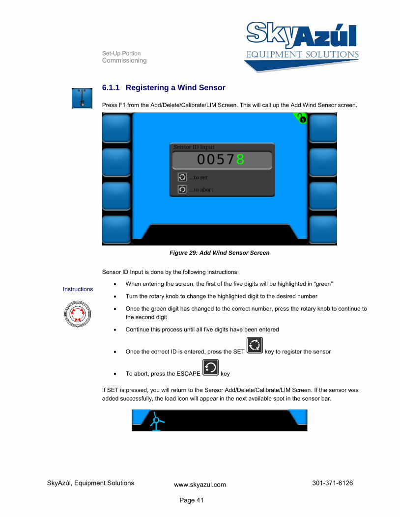
6.1.1 Registering a Wind Sensor
Press F1 from the Add/Delete/Calibrate/LIM Screen. This will call up the Add Wind Sensor screen.
Figure 29: Add Wind Sensor Screen
Sensor ID Input is done by the following instructions:
When entering the screen, the first of the five digits will be highlighted in “green”
Turn the rotary knob to change the highlighted digit to the desired number
Once the green digit has changed to the correct number, press the rotary knob to continue to the second digit
Continue this process until all five digits have been entered
Once the correct ID is entered, press the SET key to register the sensor
To abort, press the ESCAPE key
If SET is pressed, you will return to the Sensor Add/Delete/Calibrate/LIM Screen. If the sensor was added successfully, the load icon will appear in the next available spot in the sensor bar.
Instructions
SkyAzúl, Equipment Solutions www.skyazul.com Page 41
301-371-6126

Set-Up Portion Commissioning
6.1.2 Registering a Load Sensor
Press F2 from the Add/Delete/Calibrate/LIM Screen. This will call up the Add Load Sensor screen.
Figure 30: Add Load Sensor Screen
Sensor ID Input is done by the following instructions:
When entering the screen, the first of the five digits will be highlighted in “green”
Turn the rotary knob to change the highlighted digit to the desired number
Once the green digit has changed to the correct number, press the rotary knob to continue to the second digit
Continue this process until all five digits have been entered
Once the correct ID is entered, press the SET key to register the sensor
To abort, press the ESCAPE key
If SET is pressed, you will return to the Sensor Add/Delete/Calibrate/LIM Screen. If the sensor was added successfully, the load icon will appear in the next available spot in the sensor bar.
Instructions
SkyAzúl, Equipment Solutions www.skyazul.com Page 42
301-371-6126

Set-Up Portion Commissioning
6.1.3 Registering a A2B Sensor
Press F3 from the Add/Delete/Calibrate/LIM Screen. This will call up the Add A2B Sensor screen.
Figure 31: Add A2B Sensor Screen
Sensor ID Input is done by the following instructions:
When entering the screen, the first of the five digits will be highlighted in “green”
Turn the rotary knob to change the highlighted digit to the desired number
Once the green digit has changed to the correct number, press the rotary knob to continue to the second digit
Continue this process until all five digits have been entered
Once the correct ID is entered, press the SET key to register the sensor
To abort, press the ESCAPE key
If SET is pressed, you will return to the Sensor Add/Delete/Calibrate/LIM Screen. If the sensor was added successfully, the load icon will appear in the next available spot in the sensor bar.
Instructions
SkyAzúl, Equipment Solutions www.skyazul.com Page 43
301-371-6126

Set-Up Portion Commissioning
6.1.4 Registering an Angle Sensor
Press F4 from the Add/Delete/Calibrate/LIM Screen. This will call up the Add Angle Sensor screen.
Figure 32: Add Angle Sensor Screen
Sensor ID Input is done by the following instructions:
When entering the screen, the first of the five digits will be highlighted in “green”
Turn the rotary knob to change the highlighted digit to the desired number
Once the green digit has changed to the correct number, press the rotary knob to continue to the second digit
Continue this process until all five digits have been entered
Once the correct ID is entered, press the SET key to register the sensor
To abort, press the ESCAPE key
If SET is pressed, you will return to the Sensor Add/Delete/Calibrate/LIM Screen. If the sensor was added successfully, the load icon will appear in the next available spot in the sensor bar.
Instructions
SkyAzúl, Equipment Solutions www.skyazul.com Page 44
301-371-6126

Set-Up Portion Commissioning
6.2 Deleting (Removing) Sensors
Wireless sensors that are no longer to be used must be deleted from the list of available sensors. To call up the Delete Sensor screen, press F6 from the Sensor Add/Delete/Calibrate/LIM Screen.
Figure 33: Delete Sensor Screen (example)
Press the corresponding function button to delete the desired sensor. When a sensor is deleted, all other sensors will keep their previous spot on the main working screen, sensor bar, and buttons.
If F7 is pressed, it will delete the sensor added to sensor spot 7.
Figure 34: Delete Sensor Screen (deletion example)
Example Screen
Example
Sensor 5
Sensor 6
Sensor 7
Sensor 8
Sensor 1
Sensor 2
Sensor 3
Sensor 4
SkyAzúl, Equipment Solutions www.skyazul.com Page 45
301-371-6126

Set-Up Portion Configuring the System
7 Configuring the System
If the system is used together with wireless load sensors, the rope reeving must be set (see Section 3.3.1). The sensor must also be calibrated (see Section 7.1.1).
CAUTION
The device is used together with wireless load sensors in lifting equipment with a multiple
reeved lifting rope, then it is of fundamental importance for a correct load display and for the
limit value monitoring to correctly input the number of rope reevings according to the actual
number of rope reevings.
Therefore, the necessary inputs may only be made by operators who are familiar with the opera-
tion of the system.
If the system is used together with wireless wind sensors, the zero point of the angle sensor must be adjusted after mounting (see Section 7.1.2).
SkyAzúl, Equipment Solutions www.skyazul.com Page 46
301-371-6126

Set-Up Portion Configuring the System
7.1 Sensor Calibration
Setting the zero point is necessary after the installation of each angle and force sensor. Pressing F7 from the Sensor Add/Delete/Calibrate/LIM Screen will call up the Sensor Calibration screen.
Figure 35: Sensor Calibration Screen (example)
Calibrate Load Sensor (see Section 7.1.1)
Calibrate Angle Sensor (see Section 7.1.2)
Sensor Calibration Screen Example
Function Keys
SkyAzúl, Equipment Solutions www.skyazul.com Page 47
301-371-6126

Set-Up Portion Configuring the System
7.1.1 Calibrating Load Sensor
Press the corresponding function button to calibrate the desired load sensor. This will bring up the Load Calibration Screen for the sensor selected.
Complete the following steps to set the zero point of the load sensor. The process can be aborted at
any time by hitting the ESCAPE key.
1. Remove all load from load sensor
2. Press to confirm this step is completed
SkyAzúl, Equipment Solutions www.skyazul.com Page 48
301-371-6126

Set-Up Portion Configuring the System
7.1.2 Calibrating Angle Sensor
Press the corresponding function button to calibrate the desired angle sensor. This will bring up the Angle Calibration Screen for the sensor selected.
Complete the following steps to set the zero point of the angle sensor. The process can be aborted at
any time by hitting the ESCAPE key.
1. Fully retract boom
2. Press the SET key to confirm this step is completed
1. Boom down
2. Press the SET key to confirm this step is completed
1. Lower boom to exactly 0° using a digital level on the boom
2. Press the SET key to confirm this step is completed
SkyAzúl, Equipment Solutions www.skyazul.com Page 49
301-371-6126

Set-Up Portion Configuring the System
7.2 Limit Output Signal Setup
Limit output signals can be enabled when user set limits are exceeded for load and angle sensors. Limit output signal functionality cannot be disabled for A2B sensors. This function can be set for individual sensors or in combination. To enable/disable this feature on a sensor, press the corresponding function button from the LIM screen (see Section 3.4 for more information on setting limits).
NOTE
Relays will need to be added for Limit Output Signals! DOs 1-3 supply ground.
7.2.1 Enabling Limit Output Signals for Angle Sensors
Press the corresponding function button from the LIM screen to set the limit. This will call up the Angle Sensor Limit Screen. The lockout functionality is enabled or disabled by pressing the Digital Output button (F1).
Figure 36: Set Angle Sensor Limit Screen
Disabled
Enabled
Instructions
Enable/Disable Lockout
SkyAzúl, Equipment Solutions www.skyazul.com Page 50
301-371-6126

Set-Up Portion Configuring the System
7.2.2 Enabling Limit Output Signals for Load Sensors
Press the corresponding function button from the LIM screen to set the limit. This will call up the Load Sensor Limit Screen. The lockout functionality is enabled or disabled by pressing the Digital Output button (F1).
Figure 37: Set Load Sensor Limit Screen
Disabled
Enabled
Instructions
Enable/Disable Lockout
SkyAzúl, Equipment Solutions www.skyazul.com Page 51
301-371-6126

Set-Up Portion System Settings (Set-Up)
8 System Settings (Set-Up)
The Setup menu allows the user to configure various settings and view Digital Output statuses. Press-ing F8 from the Sensor Add/Delete/Calibrate/LIM Screen will call up the Sensor Calibration screen.
Figure 38: Setup Screen
LCD Brightness (see Section 4.1.1)
Sensor Information Transfer (see Section 8.1.2)
Key Brightness (see Section 4.1.2)
Set Units (see Section 4.1.4)
Alarm Volume (see Section 8.1.1)
Lock/Unlock System (see Section 8.1.3)
Digital Outputs (see Section 4.1.3)
NOTE
The symbol indicates that the screen is password protected. If the system is not unlocked, pressing password protect function buttons will have no function.
See Section 8.1.3 for more information on unlocking the system.
Function Keys
SkyAzúl, Equipment Solutions www.skyazul.com Page 52
301-371-6126

Set-Up Portion System Settings (Set-Up)
8.1.1 Alarm Volume
The volume of the audible alarm is able to be adjusted from 5% to 100%. Pressing F3 from the Setup Screen will call up the LCD Brightness Screen.
Figure 39: Alarm Volume Screen
Alarm Volume is set by the following instructions:
Turn the rotary knob to change the Alarm Volume between 5% and 100%
Once the desired volume is selected, press the SET key to set.
To abort, press the ESCAPE key
Instructions
SkyAzúl, Equipment Solutions www.skyazul.com Page 53
301-371-6126

Set-Up Portion System Settings (Set-Up)
8.1.2 Sensor Information Transfer
The sensor IDs set in Section 6.1 are stored on both the vSCALE D2 console and the TRS 10-W2 wire-less receiver. This is so sensor IDs do not have to be re-entered in the event of having to replace either the vSCALE D2 console or the TRS 10-W2.
In the event the console would need replaced, selecting F5 from the Sensor Screen will transfer the sensor ID information stored on the existing TRS 10-W2 to the new console.
In the event the TRS10-W2 would need replaced, selecting F5 from the Sensor Screen will transfer the sensor ID information stored on the existing console to the new TRS 10-W2.
The Sensor Information Transfer button will have no function if there is sensor information stored on both the console and TRS 10-W2.
SkyAzúl, Equipment Solutions www.skyazul.com Page 54
301-371-6126
Set-Up Portion System Settings (Set-Up)
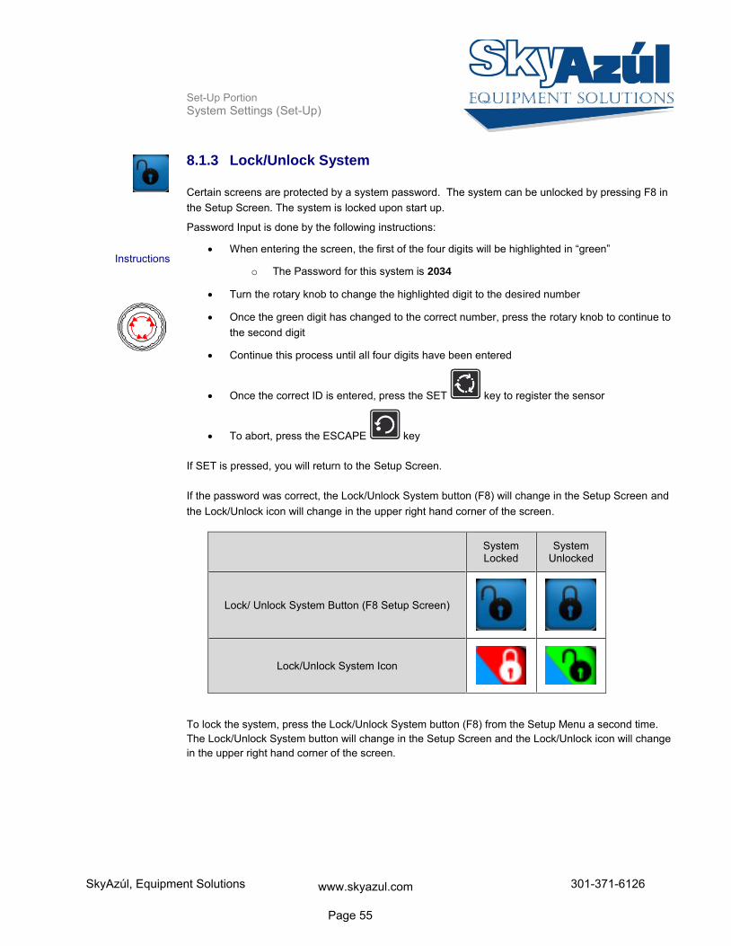
8.1.3 Lock/Unlock System
Certain screens are protected by a system password. The system can be unlocked by pressing F8 in the Setup Screen. The system is locked upon start up.
Password Input is done by the following instructions:
When entering the screen, the first of the four digits will be highlighted in “green”
o The Password for this system is 2034
Turn the rotary knob to change the highlighted digit to the desired number
Once the green digit has changed to the correct number, press the rotary knob to continue to the second digit
Continue this process until all four digits have been entered
Once the correct ID is entered, press the SET key to register the sensor
To abort, press the ESCAPE key
If SET is pressed, you will return to the Setup Screen.
If the password was correct, the Lock/Unlock System button (F8) will change in the Setup Screen and the Lock/Unlock icon will change in the upper right hand corner of the screen.
System Locked
System Unlocked
Lock/ Unlock System Button (F8 Setup Screen)
Lock/Unlock System Icon
To lock the system, press the Lock/Unlock System button (F8) from the Setup Menu a second time. The Lock/Unlock System button will change in the Setup Screen and the Lock/Unlock icon will change in the upper right hand corner of the screen.
Instructions
SkyAzúl, Equipment Solutions www.skyazul.com Page 55
301-371-6126
Set-Up Portion Service and Maintenance
9 Service and Maintenance
The vSCALE D2 operating console contains no wearing parts and therefore cannot be opened. If you notice malfunctions or differences between actual and displayed measured values, you should switch the device off and have it checked and, if necessary, repaired immediately by an authorized Hirsch-mann service partner.
You must always keep the full details contained on the type plate on hand.
Clean the surface and the front screen of the device occasionally with a damp cloth and a mild deter-gent. Never use abrasive or aggressive detergents as these may damage the device.
IMPORTANT
Device may be damaged by the use of high-pressure cleaners.
The device must not be treated with a high-pressure cleaner or similarly aggressive method
under any circumstances!
Condensation inside the vSCALE console can damage electronic components or the LCD and can condense at the inner side of the front glass/touch. Although the vSCALE console is designed as a closed housing with a Gore-Tex-Membrane for breathing, condensation may occur as a physical effect, if the console is exposed to unfavorable temperature/humidity cycles, which pumps humidity inside the housing.
Damage to the front foil can lead to the penetration of moisture and dirt into the interior of the device, which must then be properly repaired without delay.
Keep the contacts and the area around the device connectors clean and check occasionally that all connections are secure.
If parts are damaged, they must be properly repaired or replaced immediately.
Maintenance
Cleaning
Usage
Repair
SkyAzúl, Equipment Solutions www.skyazul.com Page 56
301-371-6126
Set-Up Portion Service and Maintenance
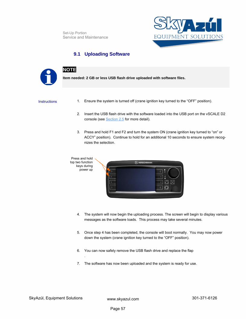
9.1 Uploading Software
NOTE
Item needed: 2 GB or less USB flash drive uploaded with software files.
1. Ensure the system is turned off (crane ignition key turned to the “OFF” position).
2. Insert the USB flash drive with the software loaded into the USB port on the vSCALE D2 console (see Section 2.5 for more detail).
3. Press and hold F1 and F2 and turn the system ON (crane ignition key turned to “on” or
ACCY” position). Continue to hold for an additional 10 seconds to ensure system recog-nizes the selection.
4. The system will now begin the uploading process. The screen will begin to display various
messages as the software loads. This process may take several minutes.
5. Once step 4 has been completed, the console will boot normally. You may now power down the system (crane ignition key turned to the “OFF” position).
6. You can now safely remove the USB flash drive and replace the flap .
7. The software has now been uploaded and the system is ready for use.
Instructions
Press and hold top two function
keys during power up
SkyAzúl, Equipment Solutions www.skyazul.com Page 57
301-371-6126

Set-Up Portion Appendix
10 Appendix
10.1 Technical Data
10.1.1 vSCALE D2
Part Number 608413 (before software)
Operating voltage 9 - 36 V DC, suitable for 12 and/or 24 V on-board power supply
Overvoltage protection overvoltage up to max. 48V DC / 2 minutes
Reverse polarity protection up to -48V DC
Display 4.3”, 95 mm(W) x 53 mm (H)
Brightness 400 cd/m²
Contrast 400:1
Illumination LED, adjustable brightness
Audible alarm built-in, output for external horn
Operating temperature range -40ºC to +75ºC
Storage temperature range -40 ºC to +85 ºC
Protection class IP 66/67, according to ISO 20653: Road Vehicles – Degrees of pro-tection (IP-code) – Protection of electrical equipment against foreign objects, water and access
Scope of supply - vSCALE D2 operating console (depending on scope of delivery with pre-fitted bracket for RAM Mount) - Mount articulated mounting
- User manual (PDF file or on data storage device)
10.1.2 TRS 10-W2
Article designation iFLEX TRS 10-W2
Article number 608799
Operating voltage 10 - 30 V DC
Fuse Self-resetting internal fuse, 500 mA
Transmission frequency 2.45 GHz, ISM band, registration/licence-free IEEE 802.15.4 standard, DSSS /OQPSK modulated Class 1 radio system in accordance with FTEG and 1999/5/EU (R&TTE)
SkyAzúl, Equipment Solutions www.skyazul.com Page 58
301-371-6126

Set-Up Portion Appendix
Antenna 2.4 GHz, with magnetic base and screwed on antenna radiator, 4m connecting cable, RP-SMA plug
Range approx. 300 m (depending upon environmental conditions)
CAN interface ISO 11898, high-speed CAN, standard identifier (11-bit)
CAN protocol CANopen slave CiA DS-301/DS401
Data rate 125 kbit/s (standard), 250 kbit/s, 500 kbit/s, 750 kbit/s, 1 Mbit/s
Node ID Standard: 31dec / 1Fhex (configurable)
CE conformity ETSI EN 300 328 ETSI EN 301 489-1 ETSI EN 300 489-17 EN 60950-1
FCC conformity FCC 47 CFR Part 15, Radio Frequency Devices, Subpart B
Control elements none
Displays 10 status LEDs for signalling various operating conditions
Electrical connection Central connector (German) 12-pole (on underside of device)
Antenna connection RP-SMA, coaxial (on the underside of the device)
Dimensions H 134 mm x W 118,2 mm x D 36,3 mm
Weight 0.262 kg (device only)
Distance between mounting holes 102,1 mm
Operating temperature range -40 ºC to +85 ºC
Storage temperature range -50 ºC to +85 ºC
Protection class IP 66/67
SkyAzúl, Equipment Solutions www.skyazul.com Page 59
301-371-6126

Set-Up Portion Appendix
10.1 Wiring Diagrams
10.1.1 System Layout
SkyAzúl, Equipment Solutions www.skyazul.com Page 60
301-371-6126

Set-Up Portion Appendix
SkyAzúl, Equipment Solutions www.skyazul.com Page 61
301-371-6126
Set-Up Portion Appendix
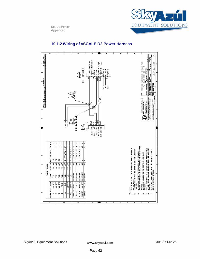
10.1.2 Wiring of vSCALE D2 Power Harness
SkyAzúl, Equipment Solutions www.skyazul.com Page 62
301-371-6126
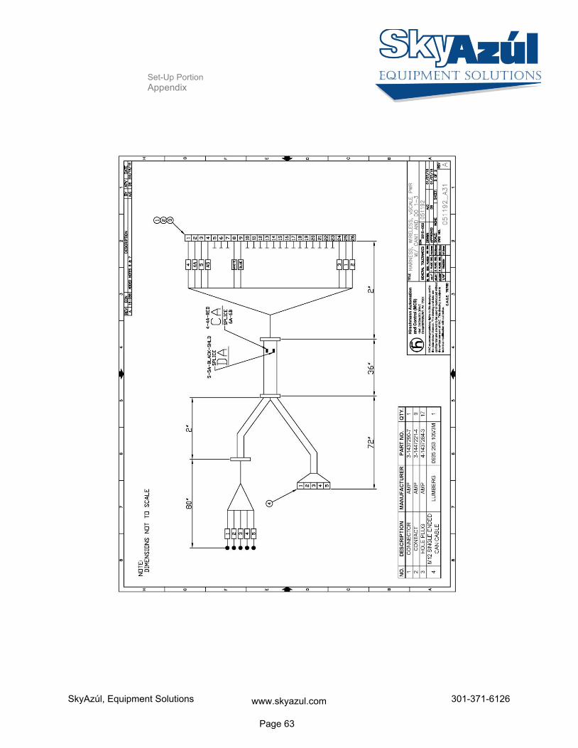
Set-Up Portion Appendix
SkyAzúl, Equipment Solutions www.skyazul.com Page 63
301-371-6126

Set-Up Portion Appendix
10.1.3 Wiring of TRS 10-W2 Power Harness
SkyAzúl, Equipment Solutions www.skyazul.com Page 64
301-371-6126


SkyAzúl, Equipment Solutions www.skyazul.com 301-371-6126
SkyAzúl, Inc. 200 W. Main Street, Suite, 2A Middletown, MD 21769 Phone 301-371-6126 Fax 301-371-0029 [email protected] www.skyazul.com
Top Related